EP4494749A1 - Method for operating electric deionizer - Google Patents
Method for operating electric deionizer Download PDFInfo
- Publication number
- EP4494749A1 EP4494749A1 EP23770530.6A EP23770530A EP4494749A1 EP 4494749 A1 EP4494749 A1 EP 4494749A1 EP 23770530 A EP23770530 A EP 23770530A EP 4494749 A1 EP4494749 A1 EP 4494749A1
- Authority
- EP
- European Patent Office
- Prior art keywords
- water
- chambers
- concentration
- desalination
- electric deionizer
- Prior art date
- Legal status (The legal status is an assumption and is not a legal conclusion. Google has not performed a legal analysis and makes no representation as to the accuracy of the status listed.)
- Pending
Links
Images


Classifications
-
- C—CHEMISTRY; METALLURGY
- C02—TREATMENT OF WATER, WASTE WATER, SEWAGE, OR SLUDGE
- C02F—TREATMENT OF WATER, WASTE WATER, SEWAGE, OR SLUDGE
- C02F1/00—Treatment of water, waste water, or sewage
- C02F1/46—Treatment of water, waste water, or sewage by electrochemical methods
- C02F1/469—Treatment of water, waste water, or sewage by electrochemical methods by electrochemical separation, e.g. by electro-osmosis, electrodialysis, electrophoresis
- C02F1/4693—Treatment of water, waste water, or sewage by electrochemical methods by electrochemical separation, e.g. by electro-osmosis, electrodialysis, electrophoresis electrodialysis
- C02F1/4695—Treatment of water, waste water, or sewage by electrochemical methods by electrochemical separation, e.g. by electro-osmosis, electrodialysis, electrophoresis electrodialysis electrodeionisation
-
- B—PERFORMING OPERATIONS; TRANSPORTING
- B01—PHYSICAL OR CHEMICAL PROCESSES OR APPARATUS IN GENERAL
- B01D—SEPARATION
- B01D61/00—Processes of separation using semi-permeable membranes, e.g. dialysis, osmosis or ultrafiltration; Apparatus, accessories or auxiliary operations specially adapted therefor
- B01D61/42—Electrodialysis; Electro-osmosis ; Electro-ultrafiltration; Membrane capacitive deionization
- B01D61/44—Ion-selective electrodialysis
- B01D61/46—Apparatus therefor
- B01D61/48—Apparatus therefor having one or more compartments filled with ion-exchange material, e.g. electrodeionisation
-
- B—PERFORMING OPERATIONS; TRANSPORTING
- B01—PHYSICAL OR CHEMICAL PROCESSES OR APPARATUS IN GENERAL
- B01D—SEPARATION
- B01D61/00—Processes of separation using semi-permeable membranes, e.g. dialysis, osmosis or ultrafiltration; Apparatus, accessories or auxiliary operations specially adapted therefor
- B01D61/42—Electrodialysis; Electro-osmosis ; Electro-ultrafiltration; Membrane capacitive deionization
- B01D61/44—Ion-selective electrodialysis
- B01D61/54—Controlling or regulating
-
- C—CHEMISTRY; METALLURGY
- C02—TREATMENT OF WATER, WASTE WATER, SEWAGE, OR SLUDGE
- C02F—TREATMENT OF WATER, WASTE WATER, SEWAGE, OR SLUDGE
- C02F1/00—Treatment of water, waste water, or sewage
- C02F1/42—Treatment of water, waste water, or sewage by ion-exchange
-
- C—CHEMISTRY; METALLURGY
- C02—TREATMENT OF WATER, WASTE WATER, SEWAGE, OR SLUDGE
- C02F—TREATMENT OF WATER, WASTE WATER, SEWAGE, OR SLUDGE
- C02F1/00—Treatment of water, waste water, or sewage
- C02F1/46—Treatment of water, waste water, or sewage by electrochemical methods
- C02F1/469—Treatment of water, waste water, or sewage by electrochemical methods by electrochemical separation, e.g. by electro-osmosis, electrodialysis, electrophoresis
-
- C—CHEMISTRY; METALLURGY
- C02—TREATMENT OF WATER, WASTE WATER, SEWAGE, OR SLUDGE
- C02F—TREATMENT OF WATER, WASTE WATER, SEWAGE, OR SLUDGE
- C02F2201/00—Apparatus for treatment of water, waste water or sewage
- C02F2201/46—Apparatus for electrochemical processes
- C02F2201/461—Electrolysis apparatus
- C02F2201/46105—Details relating to the electrolytic devices
- C02F2201/4611—Fluid flow
-
- C—CHEMISTRY; METALLURGY
- C02—TREATMENT OF WATER, WASTE WATER, SEWAGE, OR SLUDGE
- C02F—TREATMENT OF WATER, WASTE WATER, SEWAGE, OR SLUDGE
- C02F2201/00—Apparatus for treatment of water, waste water or sewage
- C02F2201/46—Apparatus for electrochemical processes
- C02F2201/461—Electrolysis apparatus
- C02F2201/46105—Details relating to the electrolytic devices
- C02F2201/46115—Electrolytic cell with membranes or diaphragms
-
- C—CHEMISTRY; METALLURGY
- C02—TREATMENT OF WATER, WASTE WATER, SEWAGE, OR SLUDGE
- C02F—TREATMENT OF WATER, WASTE WATER, SEWAGE, OR SLUDGE
- C02F2201/00—Apparatus for treatment of water, waste water or sewage
- C02F2201/46—Apparatus for electrochemical processes
- C02F2201/461—Electrolysis apparatus
- C02F2201/46105—Details relating to the electrolytic devices
- C02F2201/4612—Controlling or monitoring
- C02F2201/46125—Electrical variables
-
- C—CHEMISTRY; METALLURGY
- C02—TREATMENT OF WATER, WASTE WATER, SEWAGE, OR SLUDGE
- C02F—TREATMENT OF WATER, WASTE WATER, SEWAGE, OR SLUDGE
- C02F2209/00—Controlling or monitoring parameters in water treatment
- C02F2209/05—Conductivity or salinity
-
- Y—GENERAL TAGGING OF NEW TECHNOLOGICAL DEVELOPMENTS; GENERAL TAGGING OF CROSS-SECTIONAL TECHNOLOGIES SPANNING OVER SEVERAL SECTIONS OF THE IPC; TECHNICAL SUBJECTS COVERED BY FORMER USPC CROSS-REFERENCE ART COLLECTIONS [XRACs] AND DIGESTS
- Y02—TECHNOLOGIES OR APPLICATIONS FOR MITIGATION OR ADAPTATION AGAINST CLIMATE CHANGE
- Y02A—TECHNOLOGIES FOR ADAPTATION TO CLIMATE CHANGE
- Y02A20/00—Water conservation; Efficient water supply; Efficient water use
- Y02A20/124—Water desalination
-
- Y—GENERAL TAGGING OF NEW TECHNOLOGICAL DEVELOPMENTS; GENERAL TAGGING OF CROSS-SECTIONAL TECHNOLOGIES SPANNING OVER SEVERAL SECTIONS OF THE IPC; TECHNICAL SUBJECTS COVERED BY FORMER USPC CROSS-REFERENCE ART COLLECTIONS [XRACs] AND DIGESTS
- Y02—TECHNOLOGIES OR APPLICATIONS FOR MITIGATION OR ADAPTATION AGAINST CLIMATE CHANGE
- Y02A—TECHNOLOGIES FOR ADAPTATION TO CLIMATE CHANGE
- Y02A20/00—Water conservation; Efficient water supply; Efficient water use
- Y02A20/124—Water desalination
- Y02A20/131—Reverse-osmosis
Definitions
- the present invention relates to a method for operating an electric deionizer (electric deionized water production apparatus) for producing deionized water.
- cation exchange membranes and anion exchange membranes are alternately arranged between a cathode and an anode, and desalination chambers and concentration chambers are defined and formed by these cation exchange membranes and anion exchange membranes, and the desalination chambers and concentration chambers are filled with ion exchange resin.
- membranes formed by graft polymerization of monomers having various anion exchange functions or cation exchange functions may also be used in addition to heterogeneous membranes formed by adding a binder such as polystyrene to a powdered ion exchange resin, homogeneous membranes formed by polymerization of styrene-divinylbenzene.
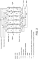
- FIG. 2 shows the basic configuration of the electric deionizer of Patent Document 1.
- an electric deionizer has cation exchange membranes (CEM) and anion exchange membranes (AEM) arranged alternately between a negative electrode and an anode, with desalination chambers and concentration chambers formed alternately by these cation exchange membranes and anion exchange membranes, and each desalination chamber and concentration chamber is filled with ion exchange resin (not shown).
- CEM cation exchange membranes
- AEM anion exchange membranes
- Such electric deionizer are used as pure water producing apparatus in various industries, such as in the semiconductor chip manufacturing process, thermal or nuclear power plants, petrochemical plants, and pharmaceutical manufacturing processes.
- an electric deionizer VNX55EP-2 As an electric deionizer for semiconductor manufacturing processes, the IP-VNX55EP-2 manufactured by Evoqua Water Technologies, LLC (558 Clark Road Tewksbury, Massachusetts 01876, USA) is commercially available. As shown in FIG. 3 , an electric deionizer VNX55EP-2 includes sub blocks 1 to 6. Each of the sub blocks 1 to 6 has a plurality of pairs of desalination chambers and concentration chambers formed by alternatingly arranged cation exchange membranes (CEM) and anion exchange membranes (AEM).
- CEM cation exchange membranes
- AEM anion exchange membranes
- feed water raw water
- concentrated water are supplied to sub blocks 1 to 3 from their respective ports.
- a portion of the feed water passes through the feed water passages (upper head parts) of the sub blocks 1 to 3 and is supplied to the feed water passages (upper head parts) of sub blocks 4 to 6.
- This feed water passes through each desalination chamber of each of the sub blocks 1 to 6, and is extracted from a treated water extraction port via a desalted water collection channel (lower head part).
- the concentrated water is supplied to the head parts (upper head parts) of the sub blocks 1 to 3, passes through each of the concentration chambers of the sub blocks 1 to 3, introduced from concentrated water collection channels (lower head parts) of the sub blocks 1 to 3 into concentrated water head parts (lower head parts) of the sub blocks 4 to 6, passed into each concentration chamber of the sub blocks 4 to 6, , and is extracted from the concentrated water outlet ports via the upper head parts of the concentrated water of the sub blocks 4 to 6.
- feed water (raw water) and concentrated water are passed into the desalination chambers and concentration chambers in cocurrent flow, while in the sub blocks 4 to 6, the feed water and concentrated water are made to flow in countercurrents (opposite directions) between the desalination chambers and concentration chambers. That is, in FIG. 3 , the feed water is passed into all the desalination chambers in a downward flow manner.
- the water-passing direction of the concentrated water is downward in the first half (sub blocks 1, 2, and 3) and upward in the second half (sub blocks 4, 5, and 6). In this way, by reversing the water-passing direction of the concentrated water between the sub blocks 1 to 3 and the sub blocks 4 to 6, the amount of concentrated water used is reduced by half.
- the sub blocks 1 and 3 of the electric deionizer VNX55EP-2 shown in FIG. 3 have 17 pairs of desalination chambers and concentration chambers, and the sub block 2 has 16 such pairs.
- the sub blocks 4 and 6 have 17 such pairs, and the sub block 5 has 16 such pairs.
- "-" indicates the cathode chamber and "+” indicates the anode chamber.
- Reference numeral 10 denotes a power box.
- Patent Document 1 JP 2020-524593
- the feed water and concentrated water are cocurrent flows, while in the sub blocks 4 to 6 they are countercurrent flows.
- the difference in ion concentration between the lower part of the desalination chamber and the lower part of the concentration chamber became large, and ions moved from the concentration chamber to the desalination chamber due to concentration diffusion, resulting in a deterioration in the quality of the treated water.
- An object of the present invention is to provide a method for operating electric deionizer capable of preventing the concentration diffusion of ions from the concentration chamber to the desalination chamber and improve water quality.
- One embodiment of the present invention relates to a method for operating electric deionizer in which concentration chambers and desalination chambers are alternately formed between an anode and a cathode by an ion exchange membrane, concentrated water flows through the concentration chambers, and water to be treated flows through the desalination chambers and extracted as product water.
- the concentrated water is passed into all of the concentration chambers in an opposite direction of a water-passing direction of the water to be treated in the desalination chambers.
- an electrical conductivity of a feed water is 0.1 mS/m to 2.0 mS/m, particularly 0.2 mS/m to 2.0 mS/m.
- an inorganic carbonate concentration of a feed water is 50 ⁇ g/L to 300 ⁇ g/L as C.
- a space velocity SV of the desalination chamber is 70/h to 150/h
- a space velocity SV of the concentration chamber is 5/h to 150/h, particularly 5/h to 50/h.
- the method for operating electric deionizer of the present invention it is possible to suppress the concentration diffusion of ions from the concentration chamber to the desalination chamber. Thereby, the acceptable range of feed water quality can be expanded and the number of downstream treatment mechanisms can be reduced. Moreover, the equipment can be simplified.
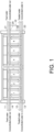
- the electric deionizer of FIG. 1 like the electric deionizer of FIG. 3 , has sub blocks 1, 2, and 3 having multiple pairs of desalination chambers and concentration chambers between a cathode chamber "-" and an anode chamber “+”, and similar sub blocks 4, 5, and 6.
- Feed water is supplied to feed water head part (upper head part) of the sub blocks 1 to 3 and the sub blocks 4 to 6 from feed water ports 11 and 21, respectively.
- feed water is passed into all the desalination chambers in a downward flow manner.
- Treated water (desalted water) from the sub blocks 1 to 3 is extracted from a treated water outflow port 12 via the lower head part.
- Treated water (desalted water) from the sub blocks 4 to 6 is extracted from a treated water outflow port 22 via the lower head part.
- concentrated water is supplied from concentrated water inflow ports 13, 23 to the concentrated water head part (lower head part) of the sub blocks 1 to 3 and sub blocks 4 to 6, respectively, and the concentrated water is passed into all the concentration chambers in an upward manner.
- the concentrated water from the sub blocks 1 to 3 is extracted from a concentrated water outflow port 14 via the upper head part.
- the concentrated water from the sub blocks 4 to 6 is extracted from a concentrated water outflow port 24 via the upper head part.
- the feed water (water to be treated) and the concentrated water flow are passed into the desalination chambers and the concentration chambers in countercurrent flow. That is, in each of the sub blocks 1 to 6 in FIG. 1 , feed water is passed into all the desalination chambers in a downward flow manner, and concentrated water is passed into all the concentration chambers in an upward flow manner.
- the water-passing direction is not limited to up-down direction, but may be horizontal or the like.
- the other configurations in FIG. 1 are the same as those in FIG. 3 .
- the space velocity SV of the desalination chamber is preferably 70/h to 150/h, and more preferably 100/h to 120/h.
- the space velocity SV of the concentration chamber is preferably 5/h to 150/h, more preferably 5/h to 50/h, and even more preferably 10/h to 25/h.
- the recovery rate is preferably 80% to 99%, particularly preferably 90% to 95%.
- the current to be passed is preferably 0.15 A/(m 3 /h) to 2.30 A/(m 3 /h), and more preferably 0.7 A/(m 3 /h) to 1.2 A/(m 3 /h).
- the feed water quality is preferably 0.1 mS/m to 2.0 mS/m, particularly preferably 0.2 mS/m to 2.0 mS/m, and even more preferably 0.3 mS/m to 1.0 mS/m.
- the IC (inorganic carbonate) concentration of the feed water is preferably 50 ⁇ g/L to 300 ⁇ g/L (as C), more preferably ⁇ g/L 100 to 200 ⁇ g/L (as C).
- FIG. 1 a total of six sub blocks are provided, three on each side, but the number is not limited thereto, as long as there are about one to six.
- the number of pairs of desalination chambers and concentration chambers in one Sub block may be about 1 to 100.
- the electric deionizer used was an IP-VNX55EP-2 manufactured by Evoqua Water Technologies, LLC (558 Clark Road Tewksbury, Massachusetts 01876, USA).
- the water-passing method of the feed water and the concentrated water was as shown in FIG. 1 in Example 1, and as shown in FIG. 3 in Comparative Example 1.
- Other conditions are as follows:
- the change in the treated water resistivity over time is shown in FIG. 4 .
- the period from the start of water flow to 150 hours (0 to 150 hours) is Comparative Example 1, and the period from 150 hours onwards is Example 1.
- Comparative Example 1 As shown in FIG. 4 , in Comparative Example 1, it was not possible to increase the treated water resistivity to 16 M ⁇ cm or more, whereas in Example 1, it was possible to increase the treated water resistivity to 18 M ⁇ cm.
Landscapes
- Chemical & Material Sciences (AREA)
- Engineering & Computer Science (AREA)
- Water Supply & Treatment (AREA)
- Chemical Kinetics & Catalysis (AREA)
- Life Sciences & Earth Sciences (AREA)
- Health & Medical Sciences (AREA)
- Hydrology & Water Resources (AREA)
- Environmental & Geological Engineering (AREA)
- Organic Chemistry (AREA)
- Analytical Chemistry (AREA)
- Molecular Biology (AREA)
- Electrochemistry (AREA)
- General Chemical & Material Sciences (AREA)
- Urology & Nephrology (AREA)
- Water Treatment By Electricity Or Magnetism (AREA)
- Separation Using Semi-Permeable Membranes (AREA)
Abstract
Description
- The present invention relates to a method for operating an electric deionizer (electric deionized water production apparatus) for producing deionized water.
- Generally, in an electric deionizer, cation exchange membranes and anion exchange membranes are alternately arranged between a cathode and an anode, and desalination chambers and concentration chambers are defined and formed by these cation exchange membranes and anion exchange membranes, and the desalination chambers and concentration chambers are filled with ion exchange resin. As ion exchange membranes such as cation exchange membranes and anion exchange membranes, membranes formed by graft polymerization of monomers having various anion exchange functions or cation exchange functions may also be used in addition to heterogeneous membranes formed by adding a binder such as polystyrene to a powdered ion exchange resin, homogeneous membranes formed by polymerization of styrene-divinylbenzene.
-
FIG. 2 shows the basic configuration of the electric deionizer of Patent Document 1. As shown in the drawing, an electric deionizer has cation exchange membranes (CEM) and anion exchange membranes (AEM) arranged alternately between a negative electrode and an anode, with desalination chambers and concentration chambers formed alternately by these cation exchange membranes and anion exchange membranes, and each desalination chamber and concentration chamber is filled with ion exchange resin (not shown). - In the electric deionizer as described above, when raw water is passed through the desalination chamber and concentrated water is passed through the concentration chamber and an electric current is applied between the cathode and anode, ions move from the desalination chamber through the anion exchange membrane and cation exchange membrane to the concentration chamber, and deionized water (pure water) is obtained as the outflow water from the desalination chamber. The concentrated water flowing out from the concentration chamber is either discarded or partially recycled.
- Such electric deionizer are used as pure water producing apparatus in various industries, such as in the semiconductor chip manufacturing process, thermal or nuclear power plants, petrochemical plants, and pharmaceutical manufacturing processes.
- The semiconductor market in particular demands high quality product water, and in many cases requires a treated water resistivity of 15 MΩ·cm or more and a high boron and silica removal rate. Moreover, in recent years, there has been a demand for setting operating conditions that take into account not only high purity of treated water but also power and water conservation.
- As an electric deionizer for semiconductor manufacturing processes, the IP-VNX55EP-2 manufactured by Evoqua Water Technologies, LLC (558 Clark Road Tewksbury, Massachusetts 01876, USA) is commercially available. As shown in
FIG. 3 , an electric deionizer VNX55EP-2 includes sub blocks 1 to 6. Each of the sub blocks 1 to 6 has a plurality of pairs of desalination chambers and concentration chambers formed by alternatingly arranged cation exchange membranes (CEM) and anion exchange membranes (AEM). - In the method for operating shown in
FIG. 3 , feed water (raw water) and concentrated water are supplied to sub blocks 1 to 3 from their respective ports. A portion of the feed water passes through the feed water passages (upper head parts) of the sub blocks 1 to 3 and is supplied to the feed water passages (upper head parts) ofsub blocks 4 to 6. This feed water passes through each desalination chamber of each of the sub blocks 1 to 6, and is extracted from a treated water extraction port via a desalted water collection channel (lower head part). - The concentrated water is supplied to the head parts (upper head parts) of the sub blocks 1 to 3, passes through each of the concentration chambers of the sub blocks 1 to 3, introduced from concentrated water collection channels (lower head parts) of the sub blocks 1 to 3 into concentrated water head parts (lower head parts) of the
sub blocks 4 to 6, passed into each concentration chamber of thesub blocks 4 to 6, , and is extracted from the concentrated water outlet ports via the upper head parts of the concentrated water of thesub blocks 4 to 6. - In the method for operating the electric deionizer VNX55EP-2, in the sub blocks 1 to 3, feed water (raw water) and concentrated water are passed into the desalination chambers and concentration chambers in cocurrent flow, while in the
sub blocks 4 to 6, the feed water and concentrated water are made to flow in countercurrents (opposite directions) between the desalination chambers and concentration chambers. That is, inFIG. 3 , the feed water is passed into all the desalination chambers in a downward flow manner. On the other hand, the water-passing direction of the concentrated water is downward in the first half (sub blocks 1, 2, and 3) and upward in the second half (sub blocks sub blocks 4 to 6, the amount of concentrated water used is reduced by half. - However, with this water-passing method, the difference in ion concentration between the lower part of the desalination chamber and the lower part of the concentration chamber in the sub blocks 1 to 3 becomes large, causing ions to move from the concentration chamber to the desalination chamber due to concentration diffusion, resulting in a deterioration in the quality of the treated water.
- Therefore, in order to obtain high purity product water, it is necessary to install a mechanism for reducing the ionic load of the feed water (e.g. a reverse osmosis membrane device or a membrane deaeration device) upstream of the electric deionizer, and to install a mechanism for further removing ions downstream. As a result, the number of devices in the facility increases, which results in an increase in installation space, an increase in costs, and an increase in power consumption.
- The
sub blocks 1 and 3 of the electric deionizer VNX55EP-2 shown inFIG. 3 have 17 pairs of desalination chambers and concentration chambers, and thesub block 2 has 16 such pairs. Thesub blocks sub block 5 has 16 such pairs. InFIG. 3 , "-" indicates the cathode chamber and "+" indicates the anode chamber.Reference numeral 10 denotes a power box. - Patent Document 1:
JP 2020-524593 - As described above, in the water-passing manner of the electric deionizer of
FIG. 3 , in the sub blocks 1 to 3, the feed water and concentrated water are cocurrent flows, while in thesub blocks 4 to 6 they are countercurrent flows. As a result, in the sub blocks 1 to 3, the difference in ion concentration between the lower part of the desalination chamber and the lower part of the concentration chamber became large, and ions moved from the concentration chamber to the desalination chamber due to concentration diffusion, resulting in a deterioration in the quality of the treated water. - An object of the present invention is to provide a method for operating electric deionizer capable of preventing the concentration diffusion of ions from the concentration chamber to the desalination chamber and improve water quality.
- One embodiment of the present invention relates to a method for operating electric deionizer in which concentration chambers and desalination chambers are alternately formed between an anode and a cathode by an ion exchange membrane, concentrated water flows through the concentration chambers, and water to be treated flows through the desalination chambers and extracted as product water. The concentrated water is passed into all of the concentration chambers in an opposite direction of a water-passing direction of the water to be treated in the desalination chambers.
- In one embodiment of the present invention, an electrical conductivity of a feed water is 0.1 mS/m to 2.0 mS/m, particularly 0.2 mS/m to 2.0 mS/m.
- In one embodiment of the present invention, an inorganic carbonate concentration of a feed water is 50 µg/L to 300 µg/L as C.
- In one embodiment of the present invention, a space velocity SV of the desalination chamber is 70/h to 150/h, and a space velocity SV of the concentration chamber is 5/h to 150/h, particularly 5/h to 50/h.
- According to the method for operating electric deionizer of the present invention, it is possible to suppress the concentration diffusion of ions from the concentration chamber to the desalination chamber. Thereby, the acceptable range of feed water quality can be expanded and the number of downstream treatment mechanisms can be reduced. Moreover, the equipment can be simplified.
-
-
FIG. 1 is a flow diagram showing a method for operating electric deionizer of the present invention. -
FIG. 2 is a diagram showing the configuration of a known electric deionizer. -
FIG. 3 is a flow diagram showing a method for operating a conventional electric deionizer. -
FIG. 4 is a graph showing the results of the examples. - Hereinafter, an embodiment will be described with reference to the drawings.
- The electric deionizer of
FIG. 1 , like the electric deionizer ofFIG. 3 , hassub blocks similar sub blocks - Feed water is supplied to feed water head part (upper head part) of the sub blocks 1 to 3 and the
sub blocks 4 to 6 fromfeed water ports water outflow port 12 via the lower head part. Treated water (desalted water) from thesub blocks 4 to 6 is extracted from a treatedwater outflow port 22 via the lower head part. - Moreover, concentrated water is supplied from concentrated
water inflow ports sub blocks 4 to 6, respectively, and the concentrated water is passed into all the concentration chambers in an upward manner. The concentrated water from the sub blocks 1 to 3 is extracted from a concentratedwater outflow port 14 via the upper head part. The concentrated water from thesub blocks 4 to 6 is extracted from a concentratedwater outflow port 24 via the upper head part. - As described, in each of the sub blocks 1 to 6, the feed water (water to be treated) and the concentrated water flow are passed into the desalination chambers and the concentration chambers in countercurrent flow. That is, in each of the sub blocks 1 to 6 in
FIG. 1 , feed water is passed into all the desalination chambers in a downward flow manner, and concentrated water is passed into all the concentration chambers in an upward flow manner. Moreover, the water-passing direction is not limited to up-down direction, but may be horizontal or the like. The other configurations inFIG. 1 are the same as those inFIG. 3 . - The space velocity SV of the desalination chamber is preferably 70/h to 150/h, and more preferably 100/h to 120/h. The space velocity SV of the concentration chamber is preferably 5/h to 150/h, more preferably 5/h to 50/h, and even more preferably 10/h to 25/h. The recovery rate is preferably 80% to 99%, particularly preferably 90% to 95%. The current to be passed is preferably 0.15 A/(m3/h) to 2.30 A/(m3/h), and more preferably 0.7 A/(m3/h) to 1.2 A/(m3/h).
- The feed water quality (electrical conductivity) is preferably 0.1 mS/m to 2.0 mS/m, particularly preferably 0.2 mS/m to 2.0 mS/m, and even more preferably 0.3 mS/m to 1.0 mS/m. The IC (inorganic carbonate) concentration of the feed water is preferably 50 µg/L to 300 µg/L (as C), more preferably µg/
L 100 to 200 µg/L (as C). - In
FIG. 1 , a total of six sub blocks are provided, three on each side, but the number is not limited thereto, as long as there are about one to six. - The number of pairs of desalination chambers and concentration chambers in one Sub block may be about 1 to 100.
- The electric deionizer used was an IP-VNX55EP-2 manufactured by Evoqua Water Technologies, LLC (558 Clark Road Tewksbury, Massachusetts 01876, USA). The water-passing method of the feed water and the concentrated water was as shown in
FIG. 1 in Example 1, and as shown inFIG. 3 in Comparative Example 1. Other conditions are as follows: - Area of membrane: 0.06 m2
- Thickness of desalination chamber: 9 mm
- Thickness of concentration chamber: 4 mm
- Volume of treated water: 10.5 m3/h
- Desalination chamber SV: 100/h
- Volume of concentrated water: 0.5 m3/h
- Concentration chamber SV (Example 1): 22/h
- Concentration chamber SV (Comparative Example 1): 44/h
- Recovery rate: 95%
- Operating current value: 10A
- Current density: 0.86 A / (m3 / h)
- Conductivity of feed water: 0.5 mS/m
- IC concentration of feed water: 150 µ/L as C
- The change in the treated water resistivity over time is shown in
FIG. 4 . The period from the start of water flow to 150 hours (0 to 150 hours) is Comparative Example 1, and the period from 150 hours onwards is Example 1. - As shown in
FIG. 4 , in Comparative Example 1, it was not possible to increase the treated water resistivity to 16 MΩ·cm or more, whereas in Example 1, it was possible to increase the treated water resistivity to 18 MΩ·cm. - In the method of Comparative Example 1, by using half the usual amount of water in the first half as a downward flow and in the second half as an upward flow, the linear flow rate in the concentration chamber can be increased, preventing the accumulation of ions in the concentration chamber (and back diffusion due to concentration). However, according to the present invention, the water quality can be improved even though the linear flow rate is half that of the prior art. Thereby, it was confirmed that high purity water can be obtained by preventing back diffusion through passing the concentrated water into all concentration chambers in the opposite direction of the water-passing direction of the water to be treated in the desalination chambers.
- Although the present invention has been described in detail with reference to specific embodiments, it will be apparent to those skilled in the art that various modifications may be made without departing from the spirit and scope of the invention.
- This application is based on
Japanese Patent Application No. 2022-041516 filed on March 16, 2022 -
- 1-6 Sub block
- 11, 21 Feed water port
- 12, 22 Treated water outflow port
- 13, 23 Concentrated water inflow port
- 14, 24 Concentrated water outflow port
Claims (4)
- A method for operating electric deionizer, wherein concentration chambers and desalination chambers are alternately formed between an anode and a cathode by an ion exchange membrane, concentrated water flows through the concentration chambers, and water to be treated flows through the desalination chambers and extracted as product water, and
wherein the concentrated water is passed into all of the concentration chambers in an opposite direction of a water-passing direction of the water to be treated in the desalination chambers. - The method for operating electric deionizer according to claim 1, wherein an electrical conductivity of a feed water is 0.1 mS/m to 2.0 mS/m.
- The method for operating electric deionizer according to claim 1 or 2, wherein an inorganic carbonate concentration of a feed water is 50 µg/L to 300 µg/L as C.
- The method for operating electric deionizer according to any one of claims 1 to 3, wherein a space velocity SV of the desalination chamber is 70/h to 150/h and a space velocity SV of the concentration chamber is 5/h to 150/h.
Applications Claiming Priority (2)
| Application Number | Priority Date | Filing Date | Title |
|---|---|---|---|
| JP2022041516A JP7380730B2 (en) | 2022-03-16 | 2022-03-16 | How to operate an electrodeionization device |
| PCT/JP2023/008491 WO2023176574A1 (en) | 2022-03-16 | 2023-03-07 | Method for operating electric deionizer |
Publications (2)
| Publication Number | Publication Date |
|---|---|
| EP4494749A1 true EP4494749A1 (en) | 2025-01-22 |
| EP4494749A4 EP4494749A4 (en) | 2026-03-18 |
Family
ID=88023153
Family Applications (1)
| Application Number | Title | Priority Date | Filing Date |
|---|---|---|---|
| EP23770530.6A Pending EP4494749A4 (en) | 2022-03-16 | 2023-03-07 | Method for operating electric deionizer |
Country Status (7)
| Country | Link |
|---|---|
| US (1) | US20250162908A1 (en) |
| EP (1) | EP4494749A4 (en) |
| JP (1) | JP7380730B2 (en) |
| KR (1) | KR102776138B1 (en) |
| CN (1) | CN118804896A (en) |
| TW (1) | TW202400524A (en) |
| WO (1) | WO2023176574A1 (en) |
Family Cites Families (6)
| Publication number | Priority date | Publication date | Assignee | Title |
|---|---|---|---|---|
| JP4778664B2 (en) * | 2000-08-11 | 2011-09-21 | ジーイー・アイオニクス・インコーポレイテッド | Apparatus and method for electrodialysis |
| JP3794268B2 (en) | 2001-01-05 | 2006-07-05 | 栗田工業株式会社 | Electrodeionization apparatus and operation method thereof |
| JP4300828B2 (en) | 2003-03-07 | 2009-07-22 | 栗田工業株式会社 | Electrodeionization apparatus and operation method thereof |
| CA3064449A1 (en) | 2017-06-21 | 2018-12-27 | Evoqua Water Technologies Llc | Design of fluid manifolds in electrodialysis devices |
| JP6863510B1 (en) | 2019-12-25 | 2021-04-21 | 栗田工業株式会社 | Control method of ultrapure water production equipment |
| JP7493147B2 (en) | 2020-09-01 | 2024-05-31 | パナソニックIpマネジメント株式会社 | Door opening and closing device |
-
2022
- 2022-03-16 JP JP2022041516A patent/JP7380730B2/en active Active
-
2023
- 2023-03-07 US US18/838,220 patent/US20250162908A1/en active Pending
- 2023-03-07 WO PCT/JP2023/008491 patent/WO2023176574A1/en not_active Ceased
- 2023-03-07 KR KR1020247024635A patent/KR102776138B1/en active Active
- 2023-03-07 EP EP23770530.6A patent/EP4494749A4/en active Pending
- 2023-03-07 CN CN202380024662.XA patent/CN118804896A/en active Pending
- 2023-03-13 TW TW112109215A patent/TW202400524A/en unknown
Also Published As
| Publication number | Publication date |
|---|---|
| EP4494749A4 (en) | 2026-03-18 |
| KR20240133724A (en) | 2024-09-04 |
| JP2023136089A (en) | 2023-09-29 |
| TW202400524A (en) | 2024-01-01 |
| JP7380730B2 (en) | 2023-11-15 |
| KR102776138B1 (en) | 2025-03-07 |
| CN118804896A (en) | 2024-10-18 |
| US20250162908A1 (en) | 2025-05-22 |
| WO2023176574A1 (en) | 2023-09-21 |
Similar Documents
| Publication | Publication Date | Title |
|---|---|---|
| JP3794268B2 (en) | Electrodeionization apparatus and operation method thereof | |
| US6296751B1 (en) | Electrodeionization apparatus with scaling control | |
| EP0170895B1 (en) | Improved electrodeionization apparatus and method | |
| US12570546B2 (en) | Control method for ultrapure water producing apparatus | |
| EP2658636B1 (en) | Electrodeionization device with improved scaling resistance | |
| US20230182078A1 (en) | Electrodialysis process and bipolar membrane electrodialysis devices for silica removal | |
| KR20050024452A (en) | Electric deionizer | |
| JP6728876B2 (en) | Electric deionization device and method for producing deionized water | |
| US6565725B2 (en) | Method for producing deionized water | |
| WO1997046491A1 (en) | Process for producing deionized water by electrical deionization technique | |
| JP5295927B2 (en) | Electric deionized water production equipment | |
| JP7460012B1 (en) | Electrodeionization apparatus and method of operating same | |
| JP5145305B2 (en) | Electric deionized water production equipment | |
| US20250162908A1 (en) | Method for operating electric deionizer | |
| CN121377246A (en) | Electrodeionization device | |
| JP4819026B2 (en) | Electric deionized water production apparatus and deionized water production method | |
| JP6627943B2 (en) | Pure water production method | |
| KR20190079851A (en) | Electrodeionization with excellent boron removal efficiency | |
| WO2024202119A1 (en) | Method for operating electric deionizer | |
| JP7816616B2 (en) | Electrodeionization apparatus and its operating method | |
| US20260116793A1 (en) | Deionized water production device and method | |
| JP2001269668A (en) | Manufacturing method of pure water and device for manufacturing pure water | |
| WO2026023244A1 (en) | Electric deionization apparatus and method for operating same | |
| IL31156A (en) | Electrodialysis process | |
| KR20260029269A (en) | Pure manufacturing system and pure manufacturing method |
Legal Events
| Date | Code | Title | Description |
|---|---|---|---|
| STAA | Information on the status of an ep patent application or granted ep patent |
Free format text: STATUS: THE INTERNATIONAL PUBLICATION HAS BEEN MADE |
|
| PUAI | Public reference made under article 153(3) epc to a published international application that has entered the european phase |
Free format text: ORIGINAL CODE: 0009012 |
|
| STAA | Information on the status of an ep patent application or granted ep patent |
Free format text: STATUS: REQUEST FOR EXAMINATION WAS MADE |
|
| 17P | Request for examination filed |
Effective date: 20240828 |
|
| AK | Designated contracting states |
Kind code of ref document: A1 Designated state(s): AL AT BE BG CH CY CZ DE DK EE ES FI FR GB GR HR HU IE IS IT LI LT LU LV MC ME MK MT NL NO PL PT RO RS SE SI SK SM TR |
|
| DAV | Request for validation of the european patent (deleted) | ||
| DAX | Request for extension of the european patent (deleted) | ||
| A4 | Supplementary search report drawn up and despatched |
Effective date: 20260216 |
|
| RIC1 | Information provided on ipc code assigned before grant |
Ipc: B01D 61/54 20060101AFI20260210BHEP Ipc: C02F 1/469 20230101ALI20260210BHEP |