EP4494720A2 - Geschmiedeter bügeleisenkopf - Google Patents
Geschmiedeter bügeleisenkopf Download PDFInfo
- Publication number
- EP4494720A2 EP4494720A2 EP24214406.1A EP24214406A EP4494720A2 EP 4494720 A2 EP4494720 A2 EP 4494720A2 EP 24214406 A EP24214406 A EP 24214406A EP 4494720 A2 EP4494720 A2 EP 4494720A2
- Authority
- EP
- European Patent Office
- Prior art keywords
- golf club
- club head
- void
- insert
- iron
- Prior art date
- Legal status (The legal status is an assumption and is not a legal conclusion. Google has not performed a legal analysis and makes no representation as to the accuracy of the status listed.)
- Granted
Links
Images


Classifications
-
- A—HUMAN NECESSITIES
- A63—SPORTS; GAMES; AMUSEMENTS
- A63B—APPARATUS FOR PHYSICAL TRAINING, GYMNASTICS, SWIMMING, CLIMBING, OR FENCING; BALL GAMES; TRAINING EQUIPMENT
- A63B53/00—Golf clubs
- A63B53/04—Heads
- A63B53/047—Heads iron-type
-
- A—HUMAN NECESSITIES
- A63—SPORTS; GAMES; AMUSEMENTS
- A63B—APPARATUS FOR PHYSICAL TRAINING, GYMNASTICS, SWIMMING, CLIMBING, OR FENCING; BALL GAMES; TRAINING EQUIPMENT
- A63B53/00—Golf clubs
- A63B53/08—Golf clubs with special arrangements for obtaining a variable impact
-
- A—HUMAN NECESSITIES
- A63—SPORTS; GAMES; AMUSEMENTS
- A63B—APPARATUS FOR PHYSICAL TRAINING, GYMNASTICS, SWIMMING, CLIMBING, OR FENCING; BALL GAMES; TRAINING EQUIPMENT
- A63B60/00—Details or accessories of golf clubs, bats, rackets or the like
- A63B60/02—Ballast means for adjusting the centre of mass
-
- A—HUMAN NECESSITIES
- A63—SPORTS; GAMES; AMUSEMENTS
- A63B—APPARATUS FOR PHYSICAL TRAINING, GYMNASTICS, SWIMMING, CLIMBING, OR FENCING; BALL GAMES; TRAINING EQUIPMENT
- A63B60/00—Details or accessories of golf clubs, bats, rackets or the like
- A63B60/50—Details or accessories of golf clubs, bats, rackets or the like with through-holes
-
- A—HUMAN NECESSITIES
- A63—SPORTS; GAMES; AMUSEMENTS
- A63B—APPARATUS FOR PHYSICAL TRAINING, GYMNASTICS, SWIMMING, CLIMBING, OR FENCING; BALL GAMES; TRAINING EQUIPMENT
- A63B53/00—Golf clubs
- A63B53/04—Heads
- A63B2053/0491—Heads with added weights, e.g. changeable, replaceable
-
- A—HUMAN NECESSITIES
- A63—SPORTS; GAMES; AMUSEMENTS
- A63B—APPARATUS FOR PHYSICAL TRAINING, GYMNASTICS, SWIMMING, CLIMBING, OR FENCING; BALL GAMES; TRAINING EQUIPMENT
- A63B2209/00—Characteristics of used materials
-
- A—HUMAN NECESSITIES
- A63—SPORTS; GAMES; AMUSEMENTS
- A63B—APPARATUS FOR PHYSICAL TRAINING, GYMNASTICS, SWIMMING, CLIMBING, OR FENCING; BALL GAMES; TRAINING EQUIPMENT
- A63B2209/00—Characteristics of used materials
- A63B2209/10—Characteristics of used materials with adhesive type surfaces, i.e. hook and loop-type fastener
-
- A—HUMAN NECESSITIES
- A63—SPORTS; GAMES; AMUSEMENTS
- A63B—APPARATUS FOR PHYSICAL TRAINING, GYMNASTICS, SWIMMING, CLIMBING, OR FENCING; BALL GAMES; TRAINING EQUIPMENT
- A63B53/00—Golf clubs
- A63B53/04—Heads
- A63B53/0408—Heads characterised by specific dimensions, e.g. thickness
- A63B53/0412—Volume
Definitions
- This disclosure generally relates to a golf club head with a 3D forged, lightweight component in the back cavity.
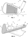
- the invention described herein is an iron-type golf club head having an optimized mass distribution while also having the aesthetics of a full muscle-back iron.
- the iron-type golf club head comprises a main club head body, a lightweight, back-cavity insert, and a void within the lightweight, back-cavity insert configured to receive a CTP weight capable of adjusting mass characteristics of the iron-type golf club head.
- This disclosure generally relates to sports equipment and relates more particularly to golf club heads and related methods.
- the iron-type golf club described herein provides both the visual aesthetic of a traditional muscle-back iron-type golf club head, the mass properties of more forgiving cavity back iron-type golf club heads, and the ability to adjust club head center of gravity provided by a detachable CTP weight.
- the iron-type golf club head comprises a back cavity, which allows more mass to be moved to the perimeter of the golf club head.
- a lightweight back cavity component or lightweight component is attached within the back cavity.
- the golf club head further comprises a CTP weight received with a void in the lightweight component allowing for the change of mass properties by configuring the mass of the CTP weight.
- the golf club head 100 can be a wedge.
- the loft angle of the golf club head 100 is less than approximately 50 degrees, less than approximately 49 degrees, less than approximately 48 degrees, less than approximately 47 degrees, less than approximately 46 degrees, less than approximately 45 degrees, less than approximately 44 degrees, less than approximately 43 degrees, less than approximately 42 degrees, less than approximately 41 degrees, or less than approximately 40 degrees. Further, in many embodiments, the loft angle of the golf club head 100 is greater than approximately 16 degrees, greater than approximately 17 degrees, greater than approximately 18 degrees, greater than approximately 19 degrees, greater than approximately 20 degrees, greater than approximately 21 degrees, greater than approximately 22 degrees, greater than approximately 23 degrees, greater than approximately 24 degrees, or greater than approximately 25 degrees.
- the loft angle of the golf club head is less than approximately 64 degrees, less than approximately 63 degrees, less than approximately 62 degrees, less than approximately 61 degrees, less than approximately 60 degrees, less than approximately 59 degrees, less than approximately 58 degrees, less than approximately 57 degrees, less than approximately 56 degrees, less than approximately 55 degrees, or less than approximately 54 degrees. Further, in many embodiments, the loft angle of the golf club head is greater than approximately 46 degrees, greater than approximately 47 degrees, greater than approximately 48 degrees, greater than approximately 49 degrees, greater than approximately 50 degrees, greater than approximately 51 degrees, or greater than approximately 52 degrees.
- the golf club head can comprise a total volume of between 1.9 cubic inches and 2.7 cubic inches. In some embodiments, the total volume of the golf club head can be between 1.9 cubic inches and 2.4 cubic inches, 2.0 cubic inches and 2.5 cubic inches, 2.1 cubic inches and 2.6 cubic inches, 2.2 cubic inches and 2.7 cubic inches, 2.3 cubic inches and 2.7 cubic inches, or 2.4 cubic inches and 2.7 cubic inches. In other embodiments, the total volume of the golf club head can be 1.9 cubic inches, 2.0 cubic inches, 2.1 cubic inches, 2.2 cubic inches, 2.3 cubic inches, 2.4 cubic inches, 2.5 cubic inches, 2.6 cubic inches, or 2.7 cubic inches.
- the golf club head can comprise a total mass of between 200 grams and 300 grams. In some embodiments, the golf club head can comprise a total mass of between 200 grams and 210 grams, 210 grams and 220 grams, 220 grams and 230 grams, 230 grams and 240 grams, 240 grams and 250 grams, 250 grams and 260 grams, 255 grams and 260 grams, 260 grams to 270 grams, 265 grams to 275 grams, 270 grams and 280 grams, 275 grams, and 280 grams, or 250 grams and 270 grams.
- the total mass can be 200 grams, 205 grams, 210 grams, 220 grams, 225 grams, 230 grams, 235 grams, 240 grams, 245 grams, 250 grams, 255 grams, 260 grams, 265 grams, 270 grams, 275 grams, 280 grams, 285 grams, 290 grams, 295 grams, or 300 grams.
- the iron-type golf club head comprises a main body having a back cavity, which allows more mass to be moved to the perimeter of the golf club head.
- a lightweight back cavity component or lightweight insert is attached within the back cavity.
- the golf club head further comprises a CTP weight received with a void in the lightweight component allowing for the change of mass properties by configuring the mass of the CTP weight to move the center of gravity of the golf club head toward the toe or toward the heel.
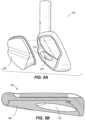
- the main body 410 of the iron-type golf club head 100 has a toe end 110, a heel end, a front having a strikeface 140 for impacting a golf ball, a hosel, a top-rail 120, a sole, a hosel configured for receiving a shaft, a rear opposite the front, and a back cavity 220 surrounded and defined by a rear surface 230 of the striking face 140, and a perimeter sidewall 460 surrounding the back cavity 220 formed by the top-rail 120, the sole 150, the toe end 110, and the heel end 130.
- the main body 410 sole 150 extends toward the rear of the main body 410 further than the top-rail 120.
- the back cavity 220 comprises a depth, and the back cavity 220 depth is greater in a lower, soleward portion than in the upper, top-rail 120 portion of the back cavity 220.
- the club head 100 defines a ground plane 1000 that is tangent to the sole 150 when the club head 100 is at an address position.
- the perimeter sidewall 460 is generally perpendicular to the rear surface 230.
- the perimeter sidewall 460 may vary from perpendicular by plus or minus 5 degrees.
- the heel end 130 of the golf club head 100 may have an aperture 210 through the heel end 130, so the aperture 210 opens to an exterior surface of the heel end 130 and opens to the back cavity 220.
- the perimeter sidewall 460 comprises a locking groove 240 in the perimeter sidewall 460 along the perimeter of the back cavity 220.
- the locking groove 240 is recessed into the perimeter sidewall 460 surrounding the rear surface 230.
- the locking groove 240 is recessed into the perimeter sidewall 460 in a direction parallel to the rear surface 230 of the striking face 140. (see Figure 2 )
- the locking groove 240 comprises a locking groove bottom and two locking groove sidewalls.
- the locking groove is open to the main body 410 back cavity 220 prior to the back cavity 220 receives the lightweight insert 430.
- the locking groove 240 can define a plane, wherein the plane intersects a center of the locking groove 240 bottom around the perimeter sidewall 460, and wherein the plane is essentially parallel to the striking face 140.
- the locking groove 240 may have a single constant depth. In other embodiments, the depth of the locking groove 240 may vary.
- the locking groove 240 may have a single, constant width. In other embodiments, the locking groove 240 width may vary.
- the locking groove 240 may be continuous around the entire perimeter sidewall 460.
- the locking groove 240 may be discontinuous, and form multiple portions separated from one another around the perimeter sidewall 460.
- the locking groove 240 may comprise projections or depressions along the locking 240 bottom.
- the locking groove 240 sidewalls may comprise depressions or recesses in locking groove 240 sidewalls wherein the depressions or recessions are perpendicular to the locking wall sidewalls 240 ( Figure not shown).
- the locking groove 240 depth may be in the range of 0.1 inch to 0.5 inch.
- the locking groove 240 depth may be 0.1, inch 0.2 inch, 0.3 inch, 0.4 inch, or 0.5 inch.
- the locking groove 240 width may be in a range of 0.1 inch to 0.5 inch.
- the locking groove 240 width may be 0.1, inch 0.2-inch, 0.3 inch, 0.4 inch, or 0.5 inch.
- the sole 150 further comprises a CTP weight groove 370.
- the CTP weight groove 370 comprises a CTP weight groove 370 axis along the length of the CTP weight groove 370 so the CTP weight groove 370 axis is equidistant from the CTP weight groove 370 edges along the length of the CTP weight groove 370 from the golf club head 100 heel end 130 to the golf club head 100 toe end 110.
- the CTP weight groove 370 axis is parallel to the rear surface 230 of the striking face 140.
- the central CTP weight groove 370 axis defines an angle with the ground plane 1000 when the golf club head is in an address position.
- the CTP weight groove 370 receives part of the length of the CTP weight 420 when the CTP weight 420 is received within the void 710.
- the CTP weight groove 370 axis angle in relation to the ground plane 1000 when the golf club head 100 is at an address position may be between 0 degrees and 30 degrees.
- the CTP weight groove 370 axis angle may be 0, 1, 2, 3, 4, 5, 6, 7, 8, 9, 10, 11, 12, 13, 14, 15, 16, 17, 18, 19, 20, 21, 22, 23, 24, 25, 26, 27, 28, 29, or 30 degrees.
- the CTP weight groove 370 comprises a length, a width, and a depth of recession.
- the CTP weight groove 370 depth of recession is measured from and in relation to the surface of the surrounding sole 150 perimeter sidewall 460 so the CTP weight groove 370 defines a recess in the sole 150 perimeter sidewall 460.
- the CTP weight groove 370 depth of recession gradually decreases from closest to the golf club head 100 heel end 130 as it extends toward the golf club head toe end 110.
- the CTP weight groove 370 depth width gradually decreases from closest to the golf club head heel end 130 as it extends toward the golf club head toe end 110.
- the CTP weight 420 groove 370 tapers to a toe end 110 termination where the CTP weight groove 370 depth and CTP weight groove 370 width are each zero.
- the CTP weight groove 370 further comprises a cross-sectional profile.
- the CTP weight groove 370 cross-sectional profile may be constant. Alternately, the CTP weight groove 370 cross-sectional profile may gradually change from closest to the golf club head heel end 130 toward the golf club head toe end 110.
- the CTP weight groove 370 cross-sectional profile may decrease from closest to the golf club head heel end 130 toward the golf club head toe end 110.
- the CTP weight groove 370 cross-sectional profile may comprise a radius of curvature.
- the CTP weight groove 370 comprises edges along the points wherein the recession from the sole 150 perimeter sidewall 460 begins.
- the golf club head 100 main body 410 further defines a hole or aperture 210 in the heel end 130 of the golf club head 100 main body 410 that extends from an outer surface of the main body 410 into the back cavity 220.
- the aperture 210 comprises a depth and a cross-sectional area.
- the aperture 210 defines a central axis wherein the aperture 210 central axis extends along with the depth of the aperture 210 through a geometric center of the aperture 210 and essentially parallel the strikeface rear surface 230.
- the aperture 210 comprises a circular cross-sectional shape having a radius of curvature.
- the aperture 210 comprises any geometric cross-sectional shape. (See Figure 2 )
- the aperture 210 extends from the exterior surface of the heel end 130 of the golf club head main body 410 through the heel end 130 of the perimeter sidewall 460.
- the central axis of the aperture 210 also extends parallel to the CTP weight groove 370 axis.
- the cross-sectional shape of the aperture 210 in the heel end 130 of the golf club main body 410 can be circular
- the cross-sectional shape of the CTP weight groove 370 can be a circular section at any location along the CTP weight groove 370 length, wherein the radius of curvature of the aperture 210 and the CTP weight groove 370 radius of curvature are the same.
- the main body 410 of the golf club head 100 can comprise steel alloys, titanium alloys, aluminum alloys, plastic polymers, carbon fibers, composites, thermoplastic composites, or any other suitable material.
- Figures 1-9 all refer to a single embodiment of the golf club head 100. All numbered features and elements are the golf club head 100 features and elements.
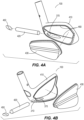
- the lightweight component 430 resides in the back cavity 220 of the main body 410 and provides a clean muscle-back aesthetic.
- the lightweight component 430 comprises an upper portion 620, a lower, muscle-back portion 640, and a transition 630 between the upper portion 620 and the lower, muscle-back portion 640.
- the upper portion 620 does not extend further rearward than the main body 410 top-rail 120.
- the lower, muscle-back portion 640 does not extend further rearward than the main body 410 sole 150.
- the upper portion 620 comprises a first insert thickness.
- the lower, muscle-back portion 640 defines a second insert thickness.
- the second insert thickness may vary.
- the second insert thickness may have a maximum thickness between the sole portion of the perimeter sidewall 460 and the insert transition 630.
- the second insert thickness is larger than the first insert thickness.
- the insert transition 630 comprises a thickness that transitions from the first insert thickness to the second insert thickness.
- the lightweight component 430 comprises a locking flange 610 configured to be received within the locking groove 240 in the perimeter sidewall 460 of the back cavity 220, providing a mechanical lock to retain the lightweight component 430 within the back cavity 220.
- the lightweight component 430 encompasses a void 710 for retaining the CTP weight 420, such that the void 710 aligns with the heel aperture 210 in the main body 410.
- the aperture 210 in the main body 410 and the void 710 in the lightweight component 430 combine to receive the CTP weight 420.
- the void 710 can be within the lower, muscle-back portion 640 of the lightweight component 430. No portion of void 710 is within the lightweight component 430 transition portion 630 or upper portion 620.
- the lightweight component 430 can surround a void 710 aligned to the aperture 210 in the heel end 130 of the golf club head 100.
- the void 710 has a length measured from the heel end 130 toward the toe end 110 parallel to the sole 150 and striking face 140 of the golf club head 100 along the CTP weight 420 groove axis.
- the void 710 has a diameter or cross-sectional width.
- the void 710 is open to the aperture 210 at the heel end 130 and closed towards the toe end 110 such that the void 710 does not extend entirely through the lightweight component 430.
- the void 710 can be a tapered cylinder with a cross-sectional shape complementary to the shape of the heel aperture 210 of the main body 410.
- the cross-sectional shape of the void 710 can be tapered, so the cross-section toward the toe-end 110 of the void 710 is smaller than the void 710 cross-section toward the main body 410 heel-end 130.
- the void 710 length can be in a range of 2.0 inches to 4.0 inches.
- the void 710 length may be 2.0 inches, 2.5 inches, 3.0 inches, 3.5 inches, or 4.0 inches.
- the void 710 diameter or cross-sectional width can be in a range of 0.25 inch to 0.75 inch.
- the void 710 diameter or cross-sectional width may be 0.25, 0.30, 0.35, 0.40, 0.45, 0.50, 0.55, 0.60, 0.65, 0.70, or 0.75 inch.
- the void 710 defines a void central axis 1010.
- the void central axis 1010 is aligned with an aperture central axis.
- the void central axis 1010 is parallel to a CTP groove axis 370.
- the void central axis 1010 can be parallel with the golf club head strikeface 140.
- the void central axis 1010 also directly aligns with the aperture 210 central axis.
- the void central axis 1010 and aperture 210 central axis align because the void 710 aligns with the aperture 210 to receive the CTP weight 420 without any turns or hindrance into the void 710.
- the void central axis 1010 may form a -5 degree to +5 degree angle with the golf club head strikeface 140; wherein a negative angle indicates that a toe ward portion of the void central axis 1010 is angled toward the golf club head strikeface 140, and a positive angle indicates that a toeward portion of the void central axis 1010 is angled away from the golf club head strikeface 140.
- the void central axis 1010 defines a void angle 1020 with the ground plane 1000 when the golf club is at an address position.
- the angle 1020 may be in a range of 0 degrees to 30 degrees.
- the void central axis angle 1020 relative to the ground plane 1000 when the golf club is at address may be 0, 1, 2, 3, 4, 5, 6, 7, 8, 9, 10, 11, 12, 13, 14, 15, 16, 17, 18, 19, 20, 21, 22, 23, 24, 25, 26, 27, 28, 29, or 30 degrees.
- the void central axis angle 1020 angles toward the top-rail 120 and toe end 110 of the golf club head 100.
- the void 710 is configured to receive the CTP weight 420.
- the CTP weight 420 also angles toward the top-rail 120 and toe end 110 of the golf club head 100 so the weight toe end portion 810 is proximate the top-rail 120 and toe end 110 of the golf club head 100 because the orientation of the CTP weight 420 is determined by the orientation of the void 710.
- the lightweight component 430 may comprise a metallic alloy having a second density that is less than the first density of the main body 410 of the iron-type golf club head 100.
- the lightweight component 430 may comprise a thermoset or thermoplastic material.
- the lightweight component 430 may be formed of die casting or squeeze casting alloys such as an aluminum, manganese, magnesium, tin, or zinc alloy.
- Figures 1-9 all refer to a single embodiment of the golf club head 100. All numbered features are the golf club head 100 features.
- the CTP weight 420 may add additional mass for the final swing-weight of the assembled club.
- the CTP weight 420 is positioned in the void 710 of the lightweight component 430.
- the CTP weight comprises a size and shape complementary to the void 710.
- the CTP weight 420 may be a tapered cylinder or some other tapered shape.
- the CTP weight 420 can comprise steel alloys, titanium alloys, aluminum alloys, plastic polymers, carbon fibers, composites, thermoplastic composites, or any other suitable material
- the CTP weight 420 can comprise a mass between 1.0g and 50.0g.
- the CTP weight 420 may have a mass of 1.0, 2.0, 3.0, 4.0, 5.0, 6.0, 7.0, 8.0, 9.0, 10.0, 11.0, 12.0, 13.0, 14.0, 15.0, 16.0, 17.0, 18.0, 19.0, 20.0, 21.0, 22.0, 23.0, 24.0, 25.0, 26.0, 27.0, 28.0, 29.0, 30.0, 31.0, 32.0, 33.0, 34.0, 35.0, 36.0, 37.0, 38.0, 39.0, 40.0, 41.0, 42.0, 43.0, 44.0, 45.0, 46.0, 48.0, 49.0, or 50.0 grams.
- the CTP weight 420 can be securely attached in the void 710 by adhesives, epoxy, welding, brazing, or any other suitable joining method. Alternately, the CTP weight may be press fit within the void 710 without the use of any permanent attachment method. In the alternate case, a first CTP weight 420 is interchangeable with another CTP weight or weights 420. The alternate CTP weight or weights 420 may have mass properties and material compositions different from the first CTP weight 420.
- a stopper or cap 450 is utilized to aesthetically cover the CTP weight 420 and to provide an additional mechanical lock to the CTP weight 420 ( Figure 4 ). Alternately, the stopper or cap 450 may be the primary means of retaining the CTP weight 420 within the void 720. In some embodiments, the stopper or cap 450 can be adhesively secured. In other embodiments, the stopper or cap 450 can be secured by any other attachment means such as threads, rivets, press-fit, etc.
- the CTP weight 420 can be comprised of at least two materials so the first CTP weight 420 material has a density less than the second CTP weight 420 material.
- the CTP weight 420 may have a center portion 820, a heel end portion 830, and a toe end portion 810. Either the CTP weight 420 toe end portion 810 or heel end portion 830 can comprise the second CTP weight 420 material.
- the higher density material at either the CTP weight 420 heel end or toe end shifts the golf club head center of gravity toward the golf club head heel end 130 or toe end 110.
- the golf club head comprises a main body with a back cavity.
- a lightweight back cavity component which further comprises an internal void, is placed within the back cavity.
- a CTP weight is placed within the lightweight component internal void through an aperture in the main body heel portion.
- a cap or stopper is then used to close the heel aperture and retain the CTP within the lightweight component void.
- the lightweight back cavity component may be press-fit in a back cavity by a forging operation to both fill the back cavity of the golf club head, and to appear a more traditional muscle back golf club head.
- the lightweight back cavity component may be die-cast into the back cavity.
- the lightweight back cavity component may be injection molded from a polymer in one or more components and attached in the back cavity with an adhesive. Alternately, the lightweight back cavity component may be injection molded from a polymer directly into the back cavity.
- the final golf club head further comprises
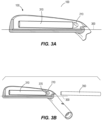
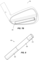
- the forging process utilizes an upper die, a lower die, and a pull rod 350
- the upper die comprises the negative shape of the lightweight component 430.
- the lower die comprises the negative shape of the main body 410 front.
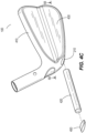
- the pull rod 350 is sized to fit through the aperture 210 in the heel of the main body 410 and into the back cavity 220 ( Figure 3B ).
- the pull rod 350 forms the size and shape of the void 710 in the lightweight component 430.
- the main body 410 may also have a CTP weight 420 groove in the lower portion of the rear cavity.
- using 3D forging beneficially enables a lightweight component 430 to be securely fastened to a golf club 100 main body 410 with a void 710 for placing a CTP weight 420.
- the final geometry of a part is very simplistic due to the limitations of the forging process, which would not allow for a void 710 to be produced.
- a post-processing step such as machining would have to be used.
- Using the 3D forging process to create the void 710 is more cost-efficient than these alternative methods of producing the same feature.
- Using the lightweight component 430 can also enable inertia and center of gravity improvements for improved golf club 100 performance while maintaining an aesthetically pleasing muscle-back iron appearance.
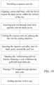
- the forging process for the lightweight component 430 comprises providing an upper, and lower forging die, wherein the upper die is configured to both receive the back portion of the main club body, and compress a billet of lightweight material to shape the muscle-back, lightweight back cavity insert; and wherein the lower die is configured to receive the main body strikeface down, placing the main body 410 into the lower forging die, orienting the back cavity 220 away from the lower forging die. (Referring to FIG.s 3A and 3B ) Placing the lightweight billet 310 into the back cavity of the main body 410.
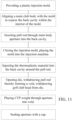
- a method to use squeeze or die casting to create a second embodiment of the golf club head 100 comprises providing a die or mold configured to receive the golf club main body 410; receiving the golf club main body 410 with the striking face 140 down and the main body 410 back cavity 220 exposed within the cavity of die or mold. Placing a pull rod 350 through the main body 410 heel aperture 210 resting in the sole 150 CTP groove 370 within the back cavity 220. Placing the die or mold into a die-cast or squeeze-cast apparatus, injecting molten or plastic lightweight material to fill the back cavity 220, shaping the lightweight insert component 430 within the back cavity 220.
- a method to use injection molding to create a third embodiment of the golf club head 100 comprises providing an injection mold configured to receive the golf club main body 410; wherein injection mold is configured to receive the golf club main body 410 with the striking face 140 down and the main body 410 back cavity 220 exposed within a cavity of an injection mold. Placing a pull rod 350 through the main body 410 heel aperture 210 resting in the 150 CTP groove 370 within the back cavity 220.
- golf equipment related to the apparatus, methods, and articles of manufacture described herein may be conforming or non-conforming to the rules of golf at any particular time. Accordingly, golf equipment related to the apparatus, methods, and articles of manufacture described herein may be advertised, offered for sale, and/or sold as conforming or non-conforming golf equipment.
- the apparatus, methods, and articles of manufacture described herein are not limited in this regard.
- the above examples may be described in connection with a wood-type golf club, the apparatus, methods, and articles of manufacture described herein.
- the apparatus, methods, and articles of manufacture described herein may be applicable to other types of sports equipment such as a hockey stick, a tennis racket, a fishing pole, a ski pole, etc.
- embodiments and limitations disclosed herein are not dedicated to the public under the doctrine of dedication if the embodiments and/or limitations: (1) are not expressly claimed in the claims; and (2) are or are potentially equivalents of express elements and/or limitations in the claims under the doctrine of equivalents.
Landscapes
- Health & Medical Sciences (AREA)
- General Health & Medical Sciences (AREA)
- Physical Education & Sports Medicine (AREA)
- Golf Clubs (AREA)
Applications Claiming Priority (3)
| Application Number | Priority Date | Filing Date | Title |
|---|---|---|---|
| US201962839411P | 2019-04-26 | 2019-04-26 | |
| PCT/US2020/029963 WO2020219987A1 (en) | 2019-04-26 | 2020-04-24 | Forged iron head |
| EP20795451.2A EP3958990B1 (de) | 2019-04-26 | 2020-04-24 | Geschmiedeter eisenkopf |
Related Parent Applications (2)
| Application Number | Title | Priority Date | Filing Date |
|---|---|---|---|
| EP20795451.2A Division EP3958990B1 (de) | 2019-04-26 | 2020-04-24 | Geschmiedeter eisenkopf |
| EP20795451.2A Division-Into EP3958990B1 (de) | 2019-04-26 | 2020-04-24 | Geschmiedeter eisenkopf |
Publications (4)
| Publication Number | Publication Date |
|---|---|
| EP4494720A2 true EP4494720A2 (de) | 2025-01-22 |
| EP4494720A3 EP4494720A3 (de) | 2025-03-19 |
| EP4494720B1 EP4494720B1 (de) | 2025-12-03 |
| EP4494720C0 EP4494720C0 (de) | 2025-12-03 |
Family
ID=72917651
Family Applications (2)
| Application Number | Title | Priority Date | Filing Date |
|---|---|---|---|
| EP20795451.2A Active EP3958990B1 (de) | 2019-04-26 | 2020-04-24 | Geschmiedeter eisenkopf |
| EP24214406.1A Active EP4494720B1 (de) | 2019-04-26 | 2020-04-24 | Geschmiedeter eisenkopf |
Family Applications Before (1)
| Application Number | Title | Priority Date | Filing Date |
|---|---|---|---|
| EP20795451.2A Active EP3958990B1 (de) | 2019-04-26 | 2020-04-24 | Geschmiedeter eisenkopf |
Country Status (6)
| Country | Link |
|---|---|
| US (2) | US11253758B2 (de) |
| EP (2) | EP3958990B1 (de) |
| JP (2) | JP7556884B2 (de) |
| KR (2) | KR102806095B1 (de) |
| GB (2) | GB2613731B (de) |
| WO (1) | WO2020219987A1 (de) |
Families Citing this family (3)
| Publication number | Priority date | Publication date | Assignee | Title |
|---|---|---|---|---|
| JP2024509539A (ja) | 2021-03-02 | 2024-03-04 | カーステン マニュファクチュアリング コーポレーション | 振動制振システム付きゴルフクラブヘッド |
| KR20250016448A (ko) | 2022-06-06 | 2025-02-03 | 카스턴 매뉴팩츄어링 코오포레이숀 | 질량 패드를 갖춘 아이언 |
| WO2025090972A1 (en) * | 2023-10-25 | 2025-05-01 | Karsten Manufacturing Corporation | Iron golf club head with multi-weight assembly |
Family Cites Families (23)
| Publication number | Priority date | Publication date | Assignee | Title |
|---|---|---|---|---|
| US3845960A (en) * | 1973-06-11 | 1974-11-05 | S Thompson | Weight-balanced golfing iron |
| US3979122A (en) | 1975-06-13 | 1976-09-07 | Belmont Peter A | Adjustably-weighted golf irons and processes |
| US5050879A (en) * | 1990-01-22 | 1991-09-24 | Cipa Manufacturing Corporation | Golf driver with variable weighting for changing center of gravity |
| JP3582812B2 (ja) | 1997-06-16 | 2004-10-27 | 株式会社遠藤製作所 | ゴルフクラブの製造方法 |
| US20020095762A1 (en) | 1997-06-16 | 2002-07-25 | Hitoshi Takeda | Method for manufacturing golf club |
| JP2004329334A (ja) | 2003-04-30 | 2004-11-25 | Endo Mfg Co Ltd | ゴルフクラブヘッドの製造方法 |
| US7338387B2 (en) * | 2003-07-28 | 2008-03-04 | Callaway Golf Company | Iron golf club |
| US7815523B2 (en) | 2004-08-11 | 2010-10-19 | Acushnet Company | Variable density golf club |
| JP2007236941A (ja) * | 2006-03-03 | 2007-09-20 | Acushnet Co | アイアン型ゴルフクラブ |
| US20070281796A1 (en) | 2006-05-31 | 2007-12-06 | Gilbert Peter J | Muscle-back iron golf clubs with higher moment of intertia and lower center of gravity |
| US7980960B2 (en) | 2006-06-09 | 2011-07-19 | Acushnet Company | Iron-type golf clubs |
| US7938739B2 (en) * | 2007-12-12 | 2011-05-10 | Karsten Manufacturing Corporation | Golf club with cavity, and method of manufacture |
| US8376878B2 (en) | 2009-05-28 | 2013-02-19 | Acushnet Company | Golf club head having variable center of gravity location |
| US8480507B2 (en) * | 2010-08-20 | 2013-07-09 | Nike, Inc. | Golf clubs and golf club heads |
| US8926451B2 (en) | 2011-11-28 | 2015-01-06 | Acushnet Company | Co-forged golf club head and method of manufacture |
| US10398951B2 (en) * | 2011-11-28 | 2019-09-03 | Acushnet Company | Co-forged golf club head and method of manufacture |
| US10420991B2 (en) | 2014-02-17 | 2019-09-24 | Karsten Manufacturing Corporation | Golf club heads with insert and related methods |
| US20160008871A1 (en) | 2014-07-14 | 2016-01-14 | Chi-Hung Su | Manufacturing method of a weight parts integratedly connected with a forged golf club head |
| US10258842B2 (en) * | 2015-12-07 | 2019-04-16 | Karsten Manufacturing Corporation | Golf club head including mechanical and adhesive joints |
| GB2564320B (en) * | 2016-03-25 | 2021-06-30 | Karsten Mfg Corp | Golf club head having a support to limit faceplate deformation |
| US9895584B1 (en) | 2016-12-14 | 2018-02-20 | Chi-Hung Su | Composite material integrally forged iron head of a golf club |
| US10625126B2 (en) * | 2016-12-29 | 2020-04-21 | Taylor Made Golf Company, Inc. | Golf club head |
| JP3213061U (ja) * | 2017-06-22 | 2017-10-19 | 正 董 | ゴルフクラブヘッドの構造 |
-
2020
- 2020-04-24 KR KR1020217038602A patent/KR102806095B1/ko active Active
- 2020-04-24 WO PCT/US2020/029963 patent/WO2020219987A1/en not_active Ceased
- 2020-04-24 EP EP20795451.2A patent/EP3958990B1/de active Active
- 2020-04-24 GB GB2303343.4A patent/GB2613731B/en active Active
- 2020-04-24 GB GB2116310.0A patent/GB2597418B/en active Active
- 2020-04-24 JP JP2021563722A patent/JP7556884B2/ja active Active
- 2020-04-24 KR KR1020257014932A patent/KR20250065739A/ko active Pending
- 2020-04-24 EP EP24214406.1A patent/EP4494720B1/de active Active
- 2020-04-24 US US16/858,520 patent/US11253758B2/en active Active
-
2022
- 2022-02-22 US US17/652,063 patent/US11745063B2/en active Active
-
2024
- 2024-09-12 JP JP2024158542A patent/JP7779972B2/ja active Active
Also Published As
| Publication number | Publication date |
|---|---|
| EP3958990A4 (de) | 2023-01-04 |
| GB2597418B (en) | 2023-04-26 |
| US11253758B2 (en) | 2022-02-22 |
| GB202116310D0 (en) | 2021-12-29 |
| US11745063B2 (en) | 2023-09-05 |
| US20200338401A1 (en) | 2020-10-29 |
| KR20250065739A (ko) | 2025-05-13 |
| GB2597418A (en) | 2022-01-26 |
| JP2022529542A (ja) | 2022-06-22 |
| EP4494720B1 (de) | 2025-12-03 |
| KR20220002509A (ko) | 2022-01-06 |
| GB2613731B (en) | 2024-01-03 |
| US20220176210A1 (en) | 2022-06-09 |
| EP4494720C0 (de) | 2025-12-03 |
| EP4494720A3 (de) | 2025-03-19 |
| JP7556884B2 (ja) | 2024-09-26 |
| JP2025000688A (ja) | 2025-01-07 |
| JP7779972B2 (ja) | 2025-12-03 |
| EP3958990C0 (de) | 2025-02-26 |
| EP3958990A1 (de) | 2022-03-02 |
| KR102806095B1 (ko) | 2025-05-09 |
| GB202303343D0 (en) | 2023-04-19 |
| WO2020219987A1 (en) | 2020-10-29 |
| EP3958990B1 (de) | 2025-02-26 |
| GB2613731A (en) | 2023-06-14 |
Similar Documents
| Publication | Publication Date | Title |
|---|---|---|
| US11745063B2 (en) | Forged iron head | |
| US10245480B2 (en) | Golf club head or other ball striking device having impact-influencing body features | |
| US20200147460A1 (en) | Golf putter head with visual alignment aid and methods of manufacture | |
| KR102657844B1 (ko) | 다중-재료 아이언 골프 클럽 헤드 | |
| AU752436B2 (en) | Golf club head | |
| US9597561B1 (en) | Golf club head having face stress-reduction features | |
| EP2854965B1 (de) | Golfschläger und golfschlägerköpfe | |
| US9764210B2 (en) | Golf club head with internal cap | |
| US6789304B2 (en) | Golf clubhead and method of manufacturing the same | |
| EP2605839B1 (de) | Golfschläger und golfschlägerköpfe | |
| US20090029791A1 (en) | Golf Clubs and Methods of Manufacture | |
| US20080028590A1 (en) | Golf club head with low density crown | |
| US20040229714A1 (en) | Iron-type golf club head and method for manufacturing it | |
| JP7789147B2 (ja) | 複数材料アイアンゴルフクラブヘッド | |
| KR20210062041A (ko) | 다단계 단조 방법 | |
| US12263385B2 (en) | Golf club head with insert | |
| US20230405410A1 (en) | Golf club ferrules and methods to manufacture golf club ferrules | |
| US12383804B2 (en) | Golf club heads and methods to manufacture golf club heads | |
| JPWO2020219987A5 (de) |
Legal Events
| Date | Code | Title | Description |
|---|---|---|---|
| PUAI | Public reference made under article 153(3) epc to a published international application that has entered the european phase |
Free format text: ORIGINAL CODE: 0009012 |
|
| STAA | Information on the status of an ep patent application or granted ep patent |
Free format text: STATUS: THE APPLICATION HAS BEEN PUBLISHED |
|
| AC | Divisional application: reference to earlier application |
Ref document number: 3958990 Country of ref document: EP Kind code of ref document: P |
|
| AK | Designated contracting states |
Kind code of ref document: A2 Designated state(s): AL AT BE BG CH CY CZ DE DK EE ES FI FR GB GR HR HU IE IS IT LI LT LU LV MC MK MT NL NO PL PT RO RS SE SI SK SM TR |
|
| REG | Reference to a national code |
Ref country code: DE Ipc: A63B0053040000 Ref country code: DE Ref legal event code: R079 Ref document number: 602020063526 Country of ref document: DE Free format text: PREVIOUS MAIN CLASS: A63B0060500000 Ipc: A63B0053040000 |
|
| PUAL | Search report despatched |
Free format text: ORIGINAL CODE: 0009013 |
|
| AK | Designated contracting states |
Kind code of ref document: A3 Designated state(s): AL AT BE BG CH CY CZ DE DK EE ES FI FR GB GR HR HU IE IS IT LI LT LU LV MC MK MT NL NO PL PT RO RS SE SI SK SM TR |
|
| RIC1 | Information provided on ipc code assigned before grant |
Ipc: A63B 60/50 20150101ALI20250213BHEP Ipc: A63B 60/02 20150101ALI20250213BHEP Ipc: A63B 53/06 20150101ALI20250213BHEP Ipc: A63B 53/04 20150101AFI20250213BHEP |
|
| STAA | Information on the status of an ep patent application or granted ep patent |
Free format text: STATUS: REQUEST FOR EXAMINATION WAS MADE |
|
| 17P | Request for examination filed |
Effective date: 20250326 |
|
| GRAP | Despatch of communication of intention to grant a patent |
Free format text: ORIGINAL CODE: EPIDOSNIGR1 |
|
| STAA | Information on the status of an ep patent application or granted ep patent |
Free format text: STATUS: GRANT OF PATENT IS INTENDED |
|
| RIC1 | Information provided on ipc code assigned before grant |
Ipc: A63B 53/04 20150101AFI20250624BHEP Ipc: A63B 53/06 20150101ALI20250624BHEP Ipc: A63B 60/02 20150101ALI20250624BHEP Ipc: A63B 60/50 20150101ALI20250624BHEP |
|
| INTG | Intention to grant announced |
Effective date: 20250703 |
|
| GRAJ | Information related to disapproval of communication of intention to grant by the applicant or resumption of examination proceedings by the epo deleted |
Free format text: ORIGINAL CODE: EPIDOSDIGR1 |
|
| STAA | Information on the status of an ep patent application or granted ep patent |
Free format text: STATUS: REQUEST FOR EXAMINATION WAS MADE |
|
| GRAP | Despatch of communication of intention to grant a patent |
Free format text: ORIGINAL CODE: EPIDOSNIGR1 |
|
| STAA | Information on the status of an ep patent application or granted ep patent |
Free format text: STATUS: GRANT OF PATENT IS INTENDED |
|
| INTC | Intention to grant announced (deleted) | ||
| INTG | Intention to grant announced |
Effective date: 20250911 |
|
| RBV | Designated contracting states (corrected) |
Designated state(s): AL AT BE BG CH CY CZ DE DK EE ES FI FR GR HR HU IE IS IT LI LT LU LV MC MK MT NL NO PL PT RO RS SE SI SK SM TR |
|
| GRAS | Grant fee paid |
Free format text: ORIGINAL CODE: EPIDOSNIGR3 |
|
| GRAA | (expected) grant |
Free format text: ORIGINAL CODE: 0009210 |
|
| STAA | Information on the status of an ep patent application or granted ep patent |
Free format text: STATUS: THE PATENT HAS BEEN GRANTED |
|
| AC | Divisional application: reference to earlier application |
Ref document number: 3958990 Country of ref document: EP Kind code of ref document: P |
|
| AK | Designated contracting states |
Kind code of ref document: B1 Designated state(s): AL AT BE BG CH CY CZ DE DK EE ES FI FR GR HR HU IE IS IT LI LT LU LV MC MK MT NL NO PL PT RO RS SE SI SK SM TR |
|
| REG | Reference to a national code |
Ref country code: CH Ref legal event code: F10 Free format text: ST27 STATUS EVENT CODE: U-0-0-F10-F00 (AS PROVIDED BY THE NATIONAL OFFICE) Effective date: 20251203 |
|
| REG | Reference to a national code |
Ref country code: DE Ref legal event code: R096 Ref document number: 602020063526 Country of ref document: DE |
|
| REG | Reference to a national code |
Ref country code: IE Ref legal event code: FG4D |
|
| U01 | Request for unitary effect filed |
Effective date: 20251212 |
|
| U07 | Unitary effect registered |
Designated state(s): AT BE BG DE DK EE FI FR IT LT LU LV MT NL PT RO SE SI Effective date: 20251218 |