EP4494614A2 - Prozessüberwachung und -steuerung während der laserbasierten brechungsindexänderung von intraokularlinsen bei patienten - Google Patents
Prozessüberwachung und -steuerung während der laserbasierten brechungsindexänderung von intraokularlinsen bei patienten Download PDFInfo
- Publication number
- EP4494614A2 EP4494614A2 EP24198078.8A EP24198078A EP4494614A2 EP 4494614 A2 EP4494614 A2 EP 4494614A2 EP 24198078 A EP24198078 A EP 24198078A EP 4494614 A2 EP4494614 A2 EP 4494614A2
- Authority
- EP
- European Patent Office
- Prior art keywords
- iol
- laser beam
- refractive index
- laser
- signal
- Prior art date
- Legal status (The legal status is an assumption and is not a legal conclusion. Google has not performed a legal analysis and makes no representation as to the accuracy of the status listed.)
- Withdrawn
Links
Images


Classifications
-
- A—HUMAN NECESSITIES
- A61—MEDICAL OR VETERINARY SCIENCE; HYGIENE
- A61F—FILTERS IMPLANTABLE INTO BLOOD VESSELS; PROSTHESES; DEVICES PROVIDING PATENCY TO, OR PREVENTING COLLAPSING OF, TUBULAR STRUCTURES OF THE BODY, e.g. STENTS; ORTHOPAEDIC, NURSING OR CONTRACEPTIVE DEVICES; FOMENTATION; TREATMENT OR PROTECTION OF EYES OR EARS; BANDAGES, DRESSINGS OR ABSORBENT PADS; FIRST-AID KITS
- A61F9/00—Methods or devices for treatment of the eyes; Devices for putting in contact-lenses; Devices to correct squinting; Apparatus to guide the blind; Protective devices for the eyes, carried on the body or in the hand
- A61F9/007—Methods or devices for eye surgery
- A61F9/008—Methods or devices for eye surgery using laser
- A61F9/00825—Methods or devices for eye surgery using laser for photodisruption
- A61F9/00827—Refractive correction, e.g. lenticle
-
- A—HUMAN NECESSITIES
- A61—MEDICAL OR VETERINARY SCIENCE; HYGIENE
- A61F—FILTERS IMPLANTABLE INTO BLOOD VESSELS; PROSTHESES; DEVICES PROVIDING PATENCY TO, OR PREVENTING COLLAPSING OF, TUBULAR STRUCTURES OF THE BODY, e.g. STENTS; ORTHOPAEDIC, NURSING OR CONTRACEPTIVE DEVICES; FOMENTATION; TREATMENT OR PROTECTION OF EYES OR EARS; BANDAGES, DRESSINGS OR ABSORBENT PADS; FIRST-AID KITS
- A61F9/00—Methods or devices for treatment of the eyes; Devices for putting in contact-lenses; Devices to correct squinting; Apparatus to guide the blind; Protective devices for the eyes, carried on the body or in the hand
- A61F9/007—Methods or devices for eye surgery
- A61F9/008—Methods or devices for eye surgery using laser
- A61F9/00825—Methods or devices for eye surgery using laser for photodisruption
- A61F9/00834—Inlays; Onlays; Intraocular lenses [IOL]
-
- A—HUMAN NECESSITIES
- A61—MEDICAL OR VETERINARY SCIENCE; HYGIENE
- A61L—METHODS OR APPARATUS FOR STERILISING MATERIALS OR OBJECTS IN GENERAL; DISINFECTION, STERILISATION OR DEODORISATION OF AIR; CHEMICAL ASPECTS OF BANDAGES, DRESSINGS, ABSORBENT PADS OR SURGICAL ARTICLES; MATERIALS FOR BANDAGES, DRESSINGS, ABSORBENT PADS OR SURGICAL ARTICLES
- A61L27/00—Materials for grafts or prostheses or for coating grafts or prostheses
- A61L27/14—Macromolecular materials
- A61L27/16—Macromolecular materials obtained by reactions only involving carbon-to-carbon unsaturated bonds
-
- A—HUMAN NECESSITIES
- A61—MEDICAL OR VETERINARY SCIENCE; HYGIENE
- A61B—DIAGNOSIS; SURGERY; IDENTIFICATION
- A61B17/00—Surgical instruments, devices or methods
- A61B2017/00017—Electrical control of surgical instruments
- A61B2017/00022—Sensing or detecting at the treatment site
- A61B2017/00057—Light
- A61B2017/00061—Light spectrum
-
- A—HUMAN NECESSITIES
- A61—MEDICAL OR VETERINARY SCIENCE; HYGIENE
- A61B—DIAGNOSIS; SURGERY; IDENTIFICATION
- A61B17/00—Surgical instruments, devices or methods
- A61B2017/00017—Electrical control of surgical instruments
- A61B2017/00137—Details of operation mode
- A61B2017/00154—Details of operation mode pulsed
-
- A—HUMAN NECESSITIES
- A61—MEDICAL OR VETERINARY SCIENCE; HYGIENE
- A61F—FILTERS IMPLANTABLE INTO BLOOD VESSELS; PROSTHESES; DEVICES PROVIDING PATENCY TO, OR PREVENTING COLLAPSING OF, TUBULAR STRUCTURES OF THE BODY, e.g. STENTS; ORTHOPAEDIC, NURSING OR CONTRACEPTIVE DEVICES; FOMENTATION; TREATMENT OR PROTECTION OF EYES OR EARS; BANDAGES, DRESSINGS OR ABSORBENT PADS; FIRST-AID KITS
- A61F9/00—Methods or devices for treatment of the eyes; Devices for putting in contact-lenses; Devices to correct squinting; Apparatus to guide the blind; Protective devices for the eyes, carried on the body or in the hand
- A61F9/007—Methods or devices for eye surgery
- A61F9/008—Methods or devices for eye surgery using laser
- A61F2009/00844—Feedback systems
- A61F2009/00851—Optical coherence topography [OCT]
-
- A—HUMAN NECESSITIES
- A61—MEDICAL OR VETERINARY SCIENCE; HYGIENE
- A61F—FILTERS IMPLANTABLE INTO BLOOD VESSELS; PROSTHESES; DEVICES PROVIDING PATENCY TO, OR PREVENTING COLLAPSING OF, TUBULAR STRUCTURES OF THE BODY, e.g. STENTS; ORTHOPAEDIC, NURSING OR CONTRACEPTIVE DEVICES; FOMENTATION; TREATMENT OR PROTECTION OF EYES OR EARS; BANDAGES, DRESSINGS OR ABSORBENT PADS; FIRST-AID KITS
- A61F9/00—Methods or devices for treatment of the eyes; Devices for putting in contact-lenses; Devices to correct squinting; Apparatus to guide the blind; Protective devices for the eyes, carried on the body or in the hand
- A61F9/007—Methods or devices for eye surgery
- A61F9/008—Methods or devices for eye surgery using laser
- A61F2009/00897—Scanning mechanisms or algorithms
-
- A—HUMAN NECESSITIES
- A61—MEDICAL OR VETERINARY SCIENCE; HYGIENE
- A61L—METHODS OR APPARATUS FOR STERILISING MATERIALS OR OBJECTS IN GENERAL; DISINFECTION, STERILISATION OR DEODORISATION OF AIR; CHEMICAL ASPECTS OF BANDAGES, DRESSINGS, ABSORBENT PADS OR SURGICAL ARTICLES; MATERIALS FOR BANDAGES, DRESSINGS, ABSORBENT PADS OR SURGICAL ARTICLES
- A61L2430/00—Materials or treatment for tissue regeneration
- A61L2430/16—Materials or treatment for tissue regeneration for reconstruction of eye parts, e.g. intraocular lens, cornea
Definitions
- This invention relates to a laser-based process of changing refractive properties of an implanted intraocular lens (IOL) by modification of the refractive index the IOL material, and in particular, it relates to process monitoring a control during laser-based in situ refractive index modification.
- IOL implanted intraocular lens
- cataract patients are left with visually significant refractive error after cataract surgery.
- This may include spherical and cylindrical power misses but also misses in matching existing higher order aberrations like chromatic aberrations.
- misses -- the mismatches between the required optical power and the actual resulting optical power of the IOL -- can be corrected post cataract surgery by modifying the lens using a laser.
- post-surgical shape correction of the IOL by UV photo cross linking and the resulting shape change has been demonstrated and commercialized, for example, by RxSight, Inc.
- the present invention is directed to a method and related apparatus for in situ modification of the refractive index of an IOL that substantially obviates one or more of the problems due to limitations and disadvantages of the related art.
- An object of the present invention is to provide non-invasive monitoring of the desired laser treatment process to ensure optimized and reliable treatment outcome. More specifically, an object of the present invention is to provide a method to monitor the process of altering the intraocular lens while it is processed in situ.
- the present invention provides a method for real-time process monitoring during laser-based refractive index modification of an intraocular lens (IOL), which includes: treating the IOL with a laser beam to modify a refractive index of a material of the IOL; while treating the IOL with the laser beam, measuring a signal from the IOL to determine a processing effect of the refractive index modification; and based on the determination, further treating the IOL with a laser beam.
- the signal measured from the IOL may be a fluorescent signal caused by the treatment laser, a fluorescent signal caused by an external illumination source, a temporary photodarkening effect, a color change, or a refractive index change directly measured by phase stabilized OCT.
- the method can be used to form a Fresnel lens in the optical zone [of the IOL]." (Abstract.)
- the IOL may be formed of a crosslinked acrylic polymer, and the refractive index modification is achieved through heating of the material.
- the laser beam may be a femtosecond pulsed laser emitting in the blue range, or the red and near infrared range, in which case the IOL material absorbs the laser light through two-photon absorption.
- the content of the ⁇ 784 application is incorporated herein by reference in its entirety.
- the effectiveness of the laser in inducing a refractive index change in the IOL material is a function of laser power.
- variability in optical transmission of the laser beam through the patient's cornea can significantly affect the laser beam power that reaches the IOL, especially considering the variability transmission of the cornea in an aged person.
- embodiments of the present invention provide methods for real-time process monitoring of the modification of the IOL, based on different underlying mechanisms. While the IOL is processed with the laser beam, a specific signal from the IOL is measured and compared to the intended signal. A control system then adjusts laser system parameters to drive the system to the intended result. The overall process is summarized in Fig. 2 .
- the treatment laser beam is scanned in the IOL to modify the refractive index of the IOL material at selected locations (step S21).
- a specific signal from the IOL e.g., fluorescence, photodarkening, color change, OCT, etc.
- the IOL while the IOL is processed with the laser beam” means when the patient's eye is continuously coupled to the laser system.
- the monitoring may occur concurrently with the laser beam scanning in the IOL, or between different laser beam scans of the treatment plan, or after the scans according to the treatment plan are completed but the laser system is still coupled to the patient's eye. All of these scenarios are referred to as real-time process monitoring.
- An advantage of the process monitoring method is that the treatment process may be automatically adjusted to achieve the desired outcome in situ. Multiple treatments (i.e., releasing the patient's eye from the laser system after an IOL modification procedure, and performing another IOL modification procedure at a later time) are not required.
- Fig. 1 schematically illustrates an ophthalmic laser surgical system 10 in which embodiments of the present invention may be implemented.
- the system 10 includes a laser device and associated beam delivery optical subsystem 11 for delivering a pulsed laser beam to the eye for treatment, an imaging subsystem 12 for detecting a signal from the eye, and a computer control subsystem 13 that performs control and data processing functions.
- the system 10 also includes an external illumination source 14.
- the imaging subsystem 12 may be implemented by different devices in the different embodiments described below. Although not shown in Fig. 1 , the imaging subsystem 12 and the beam delivery optical subsystem 11 may share certain optical components in some embodiments. Many types of ophthalmic laser surgical system are known in the art and their detailed descriptions are omitted here.
- an ophthalmic laser surgical system that includes an ultrafast laser source, a beam delivery optical subsystem including scanning devices, an OCT subsystem, an imaging subsystem such as a video monitoring subsystem for viewing an image of the eye, an aim beam subsystem, and related control subsystem.
- the treatment laser induced fluorescence (which may be referred to as auto fluorescence) of the IOL material is measured and used as an indicator of the effectiveness of the laser induced processing of the IOL.
- the fluorescence signal can then be used to automatically adjust the treatment laser and optical subsystem 11 and perform further treatment so as to achieve the intended treatment outcome.
- Monitoring may be achieved by the imaging subsystem 12 which may use a video camera of the ophthalmic laser surgical system or a separate detector which is optimized for the detection of the induced fluorescence.
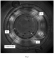
- Fig. 3 shows an example of the aforementioned process monitoring conditions which allow optimization of the laser treatment process.
- This example shows the fluorescence signal 32 in the IOL material 31 induced by irradiation of the femtosecond treatment laser.
- the more the IOL material is processed by the laser power i.e. the more change in the refractive index of the IOL material), the higher the fluorescence intensity.
- the treatment laser scans a series of circular patterns in the IOL, and this image shows a specific diameter range which is irradiated during the integration time of the video frame. Note that since autofluorescence lasts a relatively short time, other portions of the laser scan pattern are substantially not visible in the video image. Such images allow the visualization of the fluorescence, and further, the optimization of the treatment process based on the measured fluorescence intensity.
- the expected fluorescence signal is a circle with uniform intensity.
- the laser system may be adjusted to perform additional processing at that location.
- variations of the fluorescence intensity along the laser beam scan path may indicate variations in the transmission of the cornea.
- parts of the laser scan pattern may be repeated to achieve more uniform processing.
- fluorescence intensity of different scan patterns, such as different rings may be compared, and the laser system may be adjusted accordingly in response to such measurements and comparison, for example, to repeat some scan patterns that previously produced relatively weak fluorescence.
- the positions and shape of the detected fluorescence pattern in the image may also be used to determine whether laser processing occurred at intended locations of the IOL material.
- the autofluorescence signal of this embodiment may be used to monitor the refractive index modification procedure to achieve desired goals such as: (1)
- the shape of the scan pattern should be symmetrical or otherwise as intended.
- the ring pattern should be centrally symmetrical or have other desired shape such as an oval shape for astigmatism correction. Errors in this respect should be corrected.
- the scan lines should have no gap. If gaps are present, which may be due to absorption or scattering by the eye tissue or bubbles formed by the treatment laser, additional scanning (touching up) may be performed to fill the gaps.
- the relationship between the fluorescence intensity induced by a laser scan and the amount of resulting refractive index change in the IOL material caused by the same laser scan may be measured to obtain a calibration relationship between the two.
- a relationship between the measured fluorescence intensity and the corresponding laser parameters e.g. laser pulse energy
- an external fluorescence illumination source 14 (different from the treatment laser 11) is used to illuminate the IOL to induce fluorescence, which allows visualization of the fluorescence signal as indicator of the effectiveness of the laser induced processing of the IOL.
- the illumination (excitation) light wavelength may be optimized to maximize the efficacy of light conversion.
- the external illumination source 14 may be LEDs with an appropriate wavelength, or a secondary external laser light source with an appropriate wavelength.
- a wide range of excitation wavelengths are usable.
- the excitation wavelengths are in the UV- blue spectrum range, and more preferably, between 360-410 nm.
- the imaging subsystem 12 may be a video camera of the ophthalmic laser surgical system or a separate detector optimized for the detection of the induced fluorescence.
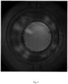
- Fig. 4 shows an example of a processed IOL 41 under illumination with a UV or blue wavelength laser source (e.g., 405 nm).
- the processed areas show increased fluorescence on the ring like phase structure 42 of a Fresnel-type lens structure.
- a UV or blue wavelength laser source e.g. 405 nm.
- the processed areas show increased fluorescence on the ring like phase structure 42 of a Fresnel-type lens structure.
- concentric rings of refractive index variation may be generated, forming a Fresnel lens.
- the fluorescence is stronger at locations with increased processing effect of the IOL material. In this image, the radially varying processing effect can be seen.
- this image is taken after multiple rings of the Fresnel-type lens structure have been formed, and all rings formed thus far are seen, which is different from autofluorescence image of the first embodiment where only the ring being scanned is seen.
- the observed fluorescence intensity or intensity variation maybe used as guidance of the IOL processing.
- the lower-left portion of the Fresnel-type lens structure has more and stronger rings than other portions, which may indicate that the refractive index modification was not spatially uniform.
- further processing of the IOL material may be performed to correct the spatial nonuniformity.
- multiple such fluorescence images may be taken from time to time to evaluate the effect of the laser processing.
- the external illumination light 14 is turned on only when the fluorescence images are being taken, although it is also possible to keep the illumination light on throughout the procedure.
- the fluorescence signal measured in the second embodiment may be used to achieve the following additional goals: (3)
- the different rings of the Fresnel-type lens structure should have desired relative amounts of laser processing.
- the radial profile of refractive index modification in the IOL should be as intended for forming the Fresnel lens, such as a sawtooth shaped profile. Errors in these respects may be corrected by additional laser scans.
- the imaging of the fluorescence signal may be combined with imaging of the IOL under a white light illumination, using the same imaging camera.
- the images under the white light illumination can reveal bubbles in the IOL material formed by the treatment laser.
- a first image with only the white light illumination is taken before treatment laser scans, and a second image (or images) with both the white light illumination and the UV-blue light illumination is taken after some laser scans.
- the first image is subtracted from the second image to obtain a difference image, which contains both bubbles generated by the laser scan and the fluorescence signal indicating the amount of refractive index change in the IOL material.
- Fig. 5 shows a processed IOL under illumination with a UV LED flash light (365 nm). Similar to Fig. 4 , the processed areas in this image show increased fluorescence on the ring like phase structure of a Fresnel-type lens structure.
- a temporary photodarkening effect which is an effect of the chemical processing of the IOL
- retro-illumination illumination from behind the IOL by light reflected from other structures of the eye
- the video camera (the imaging subsystem 12) of the ophthalmic laser system may be used to visualize and measure photodarkening effect as an indicator of the effectiveness of the laser induced processing of the IOL. Based on the observed photodarkening effect, the laser system may be adjusted and further treatment performed so as to correct possible transmission induced variances.
- Fig. 6 shows the photodarkening during processing of the IOL with the femtosecond laser. With retro illumination, the Fresnel like structure of the pattern written in the IOL is clearly visible.
- color changes in the IOL induced as a result of the treatment process may be used as an indicator of the effectiveness of the treatment.
- An external broadband light source is used to illuminate the IOL.
- the color change in the IOL may be correlated with the induced refractive index change of the IOL material in an in vitro calibration process.
- the color change measured during the treatment process may then be used as an indicator of the refractive index change achieved and then used to control the treatment process.
- the video camera of the ophthalmic laser system may be used as the imaging subsystem 12 to visualize and measure color change effect.
- Fig. 7 shows the color change caused by the processing of the IOL with the laser beam. With the illumination, the color change between the Fresnel structure of the pattern written in the IOL is clearly visible.
- the color change may be measured by the changes in ratios of the red (R), green (G) and blue (B) pixel values of the color image obtained by the video camera, for example, the ratio of R to B or the ratio of G to B.
- Other measures of color change may be used, such as by measuring a spectral shift.
- the fluorescence-based, color change and the photodarkening methods described above can monitor the chemical alterations of the IOL material. These observed signals are not direct measures of the refractive index change, but are measures of IOL properties that are a proxy for the desired refractive index change. In some embodiments, calibrations may be performed to relate these material changes to a refractive index change achieved in the material. In such embodiments, by monitoring the refractive index change in the material during treatment, the result of the treatment process can be compared with the intended refractive index change and the treatment process can be controlled to achieve the desired outcome.
- phase stabilized swept-source OCT is used to directly monitor the induced refractive index change in the IOL. It has been observed that the refractive index change in the IOL is small immediately after the treatment, but additional refractive index change occurs over a period of time such as hours or days after treatment, resulting in the final, desired refractive index change. Therefore, the phase stabilized swept-source OCT measurements during the treatment process can be correlated with long term outcomes in a clinical trial. The OCT measurements performed during the treatment process may then be used to control the treatment process to achieve the desired long term outcome using this correlation.
- the above described methods of monitoring treatment process may be applied to other ophthalmic procedures, such as LASIK refractive surgery.
Landscapes
- Health & Medical Sciences (AREA)
- Ophthalmology & Optometry (AREA)
- Life Sciences & Earth Sciences (AREA)
- Veterinary Medicine (AREA)
- Public Health (AREA)
- General Health & Medical Sciences (AREA)
- Animal Behavior & Ethology (AREA)
- Engineering & Computer Science (AREA)
- Surgery (AREA)
- Vascular Medicine (AREA)
- Heart & Thoracic Surgery (AREA)
- Biomedical Technology (AREA)
- Physics & Mathematics (AREA)
- Optics & Photonics (AREA)
- Nuclear Medicine, Radiotherapy & Molecular Imaging (AREA)
- Chemical & Material Sciences (AREA)
- Dermatology (AREA)
- Chemical Kinetics & Catalysis (AREA)
- Epidemiology (AREA)
- Medicinal Chemistry (AREA)
- Oral & Maxillofacial Surgery (AREA)
- Transplantation (AREA)
- Laser Surgery Devices (AREA)
- Prostheses (AREA)
Applications Claiming Priority (4)
| Application Number | Priority Date | Filing Date | Title |
|---|---|---|---|
| US201962832797P | 2019-04-11 | 2019-04-11 | |
| US201962925185P | 2019-10-23 | 2019-10-23 | |
| PCT/IB2020/053327 WO2020208531A1 (en) | 2019-04-11 | 2020-04-07 | Process monitoring and control during laser-based refractive index modification of intraocular lenses in patients |
| EP20719731.0A EP3952804B1 (de) | 2019-04-11 | 2020-04-07 | Prozessüberwachung und -steuerung während der laserbasierten brechungsindexänderung von intraokularlinsen bei patienten |
Related Parent Applications (1)
| Application Number | Title | Priority Date | Filing Date |
|---|---|---|---|
| EP20719731.0A Division EP3952804B1 (de) | 2019-04-11 | 2020-04-07 | Prozessüberwachung und -steuerung während der laserbasierten brechungsindexänderung von intraokularlinsen bei patienten |
Publications (2)
| Publication Number | Publication Date |
|---|---|
| EP4494614A2 true EP4494614A2 (de) | 2025-01-22 |
| EP4494614A3 EP4494614A3 (de) | 2025-04-09 |
Family
ID=70293010
Family Applications (2)
| Application Number | Title | Priority Date | Filing Date |
|---|---|---|---|
| EP24198078.8A Withdrawn EP4494614A3 (de) | 2019-04-11 | 2020-04-07 | Prozessüberwachung und -steuerung während der laserbasierten brechungsindexänderung von intraokularlinsen bei patienten |
| EP20719731.0A Active EP3952804B1 (de) | 2019-04-11 | 2020-04-07 | Prozessüberwachung und -steuerung während der laserbasierten brechungsindexänderung von intraokularlinsen bei patienten |
Family Applications After (1)
| Application Number | Title | Priority Date | Filing Date |
|---|---|---|---|
| EP20719731.0A Active EP3952804B1 (de) | 2019-04-11 | 2020-04-07 | Prozessüberwachung und -steuerung während der laserbasierten brechungsindexänderung von intraokularlinsen bei patienten |
Country Status (5)
| Country | Link |
|---|---|
| US (3) | US11540946B2 (de) |
| EP (2) | EP4494614A3 (de) |
| AU (1) | AU2020271989B2 (de) |
| CA (1) | CA3100514A1 (de) |
| WO (1) | WO2020208531A1 (de) |
Citations (1)
| Publication number | Priority date | Publication date | Assignee | Title |
|---|---|---|---|---|
| US8845625B2 (en) | 2010-01-22 | 2014-09-30 | Optimedica Corporation | Method and apparatus for automated placement of scanned laser capsulorhexis incisions |
Family Cites Families (13)
| Publication number | Priority date | Publication date | Assignee | Title |
|---|---|---|---|---|
| DE102005032041A1 (de) * | 2005-07-08 | 2007-01-18 | Carl Zeiss Meditec Ag | Vorrichtung und Verfahren zum Ändern einer optischen und/oder mechanischen Eigenschaft einer in ein Auge implantierten Linse |
| DE102006030219A1 (de) * | 2006-06-30 | 2008-01-03 | Iroc Ag | Bestrahlungssystem für medizinische Anwendungen |
| US20100082017A1 (en) * | 2008-09-26 | 2010-04-01 | Advanced Medical Optics, Inc. | Laser modification of intraocular lens |
| US10085886B2 (en) * | 2010-01-08 | 2018-10-02 | Optimedica Corporation | Method and system for modifying eye tissue and intraocular lenses |
| WO2011109039A1 (en) * | 2010-03-04 | 2011-09-09 | Aaren Scientific Inc. | System for forming and modifying lenses and lenses formed thereby |
| US10813791B2 (en) * | 2011-06-02 | 2020-10-27 | University Of Rochester | Method for modifying the refractive index of ocular tissues and applications thereof |
| US9144491B2 (en) * | 2011-06-02 | 2015-09-29 | University Of Rochester | Method for modifying the refractive index of an optical material |
| US9023016B2 (en) * | 2011-12-19 | 2015-05-05 | Alcon Lensx, Inc. | Image processor for intra-surgical optical coherence tomographic imaging of laser cataract procedures |
| US20130289543A1 (en) | 2012-04-23 | 2013-10-31 | David Haydn Mordaunt | System and method for in situ creation of a small aperture intraocular lens |
| JP6349751B2 (ja) * | 2014-02-03 | 2018-07-04 | 株式会社ニデック | 眼科用情報処理プログラム |
| WO2016077173A1 (en) * | 2014-11-10 | 2016-05-19 | University Of Houston System | Optical coherence elastography to assess biomechanics and detect progression of ocular and other tissues degenerative diseases |
| DE102015009610A1 (de) * | 2015-07-22 | 2017-01-26 | Carl Zeiss Meditec Ag | Post-operative Modifikation einer Intraokularlinse |
| WO2019193539A1 (en) | 2018-04-06 | 2019-10-10 | Optimedica Corporation | Methods and systems for changing a refractive property of an implantable intraocular lens |
-
2020
- 2020-04-07 EP EP24198078.8A patent/EP4494614A3/de not_active Withdrawn
- 2020-04-07 WO PCT/IB2020/053327 patent/WO2020208531A1/en not_active Ceased
- 2020-04-07 US US17/057,689 patent/US11540946B2/en active Active
- 2020-04-07 EP EP20719731.0A patent/EP3952804B1/de active Active
- 2020-04-07 AU AU2020271989A patent/AU2020271989B2/en active Active
- 2020-04-07 CA CA3100514A patent/CA3100514A1/en active Pending
-
2022
- 2022-12-22 US US18/145,020 patent/US12109151B2/en active Active
-
2024
- 2024-10-04 US US18/907,307 patent/US20250025344A1/en active Pending
Patent Citations (1)
| Publication number | Priority date | Publication date | Assignee | Title |
|---|---|---|---|---|
| US8845625B2 (en) | 2010-01-22 | 2014-09-30 | Optimedica Corporation | Method and apparatus for automated placement of scanned laser capsulorhexis incisions |
Also Published As
| Publication number | Publication date |
|---|---|
| EP4494614A3 (de) | 2025-04-09 |
| US20250025344A1 (en) | 2025-01-23 |
| EP3952804A1 (de) | 2022-02-16 |
| US11540946B2 (en) | 2023-01-03 |
| AU2020271989B2 (en) | 2025-12-11 |
| AU2020271989A1 (en) | 2020-12-10 |
| WO2020208531A1 (en) | 2020-10-15 |
| US12109151B2 (en) | 2024-10-08 |
| US20230130142A1 (en) | 2023-04-27 |
| CA3100514A1 (en) | 2020-10-15 |
| US20220015948A1 (en) | 2022-01-20 |
| EP3952804B1 (de) | 2024-09-04 |
Similar Documents
| Publication | Publication Date | Title |
|---|---|---|
| CN102014732B (zh) | 用于观察、检查、诊断和/或治疗眼睛的眼科设备 | |
| CN101616647B (zh) | 用于无创或微创光处理眼睛的方法和装置 | |
| JP6001240B2 (ja) | 眼に関する高精度の測定値を取得するための装置 | |
| JPH0351A (ja) | レーザ治療装置 | |
| US9022566B2 (en) | Ophthalmic device | |
| US9339185B2 (en) | Imaging apparatus that acquires a first image and, via an aberration correction unit, a second image of an area corresponding to a part of the first image | |
| CN106214323A (zh) | 激光治疗装置 | |
| US10485419B2 (en) | Optical imaging apparatus and method for controlling the same | |
| EP3412198A1 (de) | Vorrichtung für visuellen funktionstest | |
| Zielińska et al. | Pupillary light reflex induced by two-photon vision | |
| JP7420476B2 (ja) | 眼科装置、その制御方法、眼科情報処理装置、その制御方法、プログラム、及び記録媒体 | |
| US12109151B2 (en) | Process monitoring and control during laser-based refractive index modification of intraocular lenses in patients | |
| TW202320722A (zh) | 光學系統及其運作方法 | |
| Zielińska et al. | System for psychophysical measurements of two-photon vision | |
| KR102231939B1 (ko) | 안구에 조사되는 레이저 피드백장치 및 이를 이용한 레이저 피드백방법 | |
| JP2015123207A (ja) | 眼科光刺激装置 | |
| CA3100438A1 (en) | Calibration process for femtosecond laser intraocular lens modification system using video and oct targeting | |
| JP2013027672A (ja) | 眼底撮影装置 | |
| JP6127731B2 (ja) | 眼底カメラ及び画像処理プログラム | |
| US20210030588A1 (en) | Ophthalmic treatment apparatus and control method therefor | |
| US20230248296A1 (en) | A device and method for obtaining erg signals | |
| US20240189148A1 (en) | Systems and methods for modulating laser treatment on the eye | |
| KR20200097591A (ko) | 안과용 치료장치 및 이의 제어방법 | |
| WO2026048636A1 (ja) | 光照射装置及び光照射システム | |
| JP2020162914A (ja) | 眼科装置、その制御方法、眼科情報処理装置、その制御方法、プログラム、及び記録媒体 |
Legal Events
| Date | Code | Title | Description |
|---|---|---|---|
| PUAI | Public reference made under article 153(3) epc to a published international application that has entered the european phase |
Free format text: ORIGINAL CODE: 0009012 |
|
| STAA | Information on the status of an ep patent application or granted ep patent |
Free format text: STATUS: THE APPLICATION HAS BEEN PUBLISHED |
|
| AC | Divisional application: reference to earlier application |
Ref document number: 3952804 Country of ref document: EP Kind code of ref document: P |
|
| AK | Designated contracting states |
Kind code of ref document: A2 Designated state(s): AL AT BE BG CH CY CZ DE DK EE ES FI FR GB GR HR HU IE IS IT LI LT LU LV MC MK MT NL NO PL PT RO RS SE SI SK SM TR |
|
| PUAL | Search report despatched |
Free format text: ORIGINAL CODE: 0009013 |
|
| AK | Designated contracting states |
Kind code of ref document: A3 Designated state(s): AL AT BE BG CH CY CZ DE DK EE ES FI FR GB GR HR HU IE IS IT LI LT LU LV MC MK MT NL NO PL PT RO RS SE SI SK SM TR |
|
| RIC1 | Information provided on ipc code assigned before grant |
Ipc: A61F 9/008 20060101AFI20250304BHEP |
|
| STAA | Information on the status of an ep patent application or granted ep patent |
Free format text: STATUS: THE APPLICATION IS DEEMED TO BE WITHDRAWN |
|
| 18D | Application deemed to be withdrawn |
Effective date: 20251010 |