EP4494487A1 - Flavor component adsorbent and method for producing same, flavor molded body and method for producing same, heat-not-burn flavor inhaler, and flavor-generating article - Google Patents
Flavor component adsorbent and method for producing same, flavor molded body and method for producing same, heat-not-burn flavor inhaler, and flavor-generating article Download PDFInfo
- Publication number
- EP4494487A1 EP4494487A1 EP22932124.5A EP22932124A EP4494487A1 EP 4494487 A1 EP4494487 A1 EP 4494487A1 EP 22932124 A EP22932124 A EP 22932124A EP 4494487 A1 EP4494487 A1 EP 4494487A1
- Authority
- EP
- European Patent Office
- Prior art keywords
- flavor
- adsorbent
- heating
- source
- molded body
- Prior art date
- Legal status (The legal status is an assumption and is not a legal conclusion. Google has not performed a legal analysis and makes no representation as to the accuracy of the status listed.)
- Pending
Links
Images





Classifications
-
- A—HUMAN NECESSITIES
- A24—TOBACCO; CIGARS; CIGARETTES; SIMULATED SMOKING DEVICES; SMOKERS' REQUISITES
- A24B—MANUFACTURE OR PREPARATION OF TOBACCO FOR SMOKING OR CHEWING; TOBACCO; SNUFF
- A24B15/00—Chemical features or treatment of tobacco; Tobacco substitutes, e.g. in liquid form
- A24B15/18—Treatment of tobacco products or tobacco substitutes
- A24B15/24—Treatment of tobacco products or tobacco substitutes by extraction; Tobacco extracts
-
- A—HUMAN NECESSITIES
- A24—TOBACCO; CIGARS; CIGARETTES; SIMULATED SMOKING DEVICES; SMOKERS' REQUISITES
- A24B—MANUFACTURE OR PREPARATION OF TOBACCO FOR SMOKING OR CHEWING; TOBACCO; SNUFF
- A24B15/00—Chemical features or treatment of tobacco; Tobacco substitutes, e.g. in liquid form
- A24B15/10—Chemical features of tobacco products or tobacco substitutes
- A24B15/12—Chemical features of tobacco products or tobacco substitutes of reconstituted tobacco
-
- A—HUMAN NECESSITIES
- A24—TOBACCO; CIGARS; CIGARETTES; SIMULATED SMOKING DEVICES; SMOKERS' REQUISITES
- A24B—MANUFACTURE OR PREPARATION OF TOBACCO FOR SMOKING OR CHEWING; TOBACCO; SNUFF
- A24B15/00—Chemical features or treatment of tobacco; Tobacco substitutes, e.g. in liquid form
- A24B15/10—Chemical features of tobacco products or tobacco substitutes
- A24B15/16—Chemical features of tobacco products or tobacco substitutes of tobacco substitutes
- A24B15/167—Chemical features of tobacco products or tobacco substitutes of tobacco substitutes in liquid or vaporisable form, e.g. liquid compositions for electronic cigarettes
-
- A—HUMAN NECESSITIES
- A24—TOBACCO; CIGARS; CIGARETTES; SIMULATED SMOKING DEVICES; SMOKERS' REQUISITES
- A24D—CIGARS; CIGARETTES; TOBACCO SMOKE FILTERS; MOUTHPIECES OF CIGARS OR CIGARETTES; MANUFACTURE OF TOBACCO SMOKE FILTERS OR MOUTHPIECES
- A24D1/00—Cigars; Cigarettes
- A24D1/20—Cigarettes specially adapted for simulated smoking devices
-
- A—HUMAN NECESSITIES
- A24—TOBACCO; CIGARS; CIGARETTES; SIMULATED SMOKING DEVICES; SMOKERS' REQUISITES
- A24F—SMOKERS' REQUISITES; MATCH BOXES; SIMULATED SMOKING DEVICES
- A24F40/00—Electrically operated smoking devices; Component parts thereof; Manufacture thereof; Maintenance or testing thereof; Charging means specially adapted therefor
- A24F40/20—Devices using solid inhalable precursors
-
- A—HUMAN NECESSITIES
- A24—TOBACCO; CIGARS; CIGARETTES; SIMULATED SMOKING DEVICES; SMOKERS' REQUISITES
- A24F—SMOKERS' REQUISITES; MATCH BOXES; SIMULATED SMOKING DEVICES
- A24F40/00—Electrically operated smoking devices; Component parts thereof; Manufacture thereof; Maintenance or testing thereof; Charging means specially adapted therefor
- A24F40/40—Constructional details, e.g. connection of cartridges and battery parts
-
- A—HUMAN NECESSITIES
- A24—TOBACCO; CIGARS; CIGARETTES; SIMULATED SMOKING DEVICES; SMOKERS' REQUISITES
- A24F—SMOKERS' REQUISITES; MATCH BOXES; SIMULATED SMOKING DEVICES
- A24F40/00—Electrically operated smoking devices; Component parts thereof; Manufacture thereof; Maintenance or testing thereof; Charging means specially adapted therefor
- A24F40/40—Constructional details, e.g. connection of cartridges and battery parts
- A24F40/42—Cartridges or containers for inhalable precursors
-
- A—HUMAN NECESSITIES
- A24—TOBACCO; CIGARS; CIGARETTES; SIMULATED SMOKING DEVICES; SMOKERS' REQUISITES
- A24F—SMOKERS' REQUISITES; MATCH BOXES; SIMULATED SMOKING DEVICES
- A24F40/00—Electrically operated smoking devices; Component parts thereof; Manufacture thereof; Maintenance or testing thereof; Charging means specially adapted therefor
- A24F40/40—Constructional details, e.g. connection of cartridges and battery parts
- A24F40/46—Shape or structure of electric heating means
-
- A—HUMAN NECESSITIES
- A24—TOBACCO; CIGARS; CIGARETTES; SIMULATED SMOKING DEVICES; SMOKERS' REQUISITES
- A24F—SMOKERS' REQUISITES; MATCH BOXES; SIMULATED SMOKING DEVICES
- A24F40/00—Electrically operated smoking devices; Component parts thereof; Manufacture thereof; Maintenance or testing thereof; Charging means specially adapted therefor
- A24F40/40—Constructional details, e.g. connection of cartridges and battery parts
- A24F40/48—Fluid transfer means, e.g. pumps
Definitions
- the present invention relates to a flavor component adsorbent and a method for producing the same, a flavor molded body and a method for producing the same, a heat-not-burn flavor inhaler, and a flavor-generating article.
- Objects of the present invention include providing a technique for efficiently recovering flavor components from a tobacco material.
- a method for producing a flavor component adsorbent comprising:
- a flavor component adsorbent obtainable by the above-mentioned method.
- a method for producing a flavor molded body comprising:
- a heat-not-burn flavor inhaler comprising:
- a flavor-generating article comprising:
- a technique for efficiently recovering flavor components from a tobacco material is provided.
- a method for producing a flavor component adsorbent includes:
- the "adsorbent that has adsorbed the flavor components" produced by this method is referred to as a flavor component adsorbent.
- the flavor component adsorbent may be used in such a manner that it is incorporated into a heat-not-burn flavor inhaler (which may also be simply called a “heating-type flavor inhaler” below) as it is, or that it is processed into a molded body together with a molding material and then the obtained molded body is incorporated into a heating-type flavor inhaler.
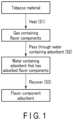
- FIG. 1 shows, in the form of a flowchart, one example of the method for producing a flavor component adsorbent.
- the heating step (S1) heats a tobacco material to vaporize flavor components from the tobacco material.
- a gas containing the flavor components is obtained (see FIG. 1 ).
- cut tobacco which is ready to be incorporated into a tobacco product such as a combustiontype or heating-type flavor inhaler
- tobacco material such as a combustiontype or heating-type flavor inhaler
- the "cut tobacco which is ready to be incorporated into a tobacco product” refers to cut tobacco which has become ready to be incorporated into a tobacco product by going through various processes including drying in a farm house, subsequent long-term aging in a leaf processing facility for one to several years, and subsequent blending and cutting in a manufacturing facility.
- the cut tobacco consists of cut pieces of leaf tobacco.
- the cut tobacco may be any of cut pieces of stemmed leaves, cut pieces of midrib, and cut pieces of reconstituted tobacco (i.e., a tobacco material obtained by processing leaf scraps, cut tobacco scraps, midrib scraps, fine powder, etc., produced in the facility processes into a reusable form), or a mixture thereof.
- the cut tobacco may be pulverized and the resulting pulverized product may be applied to the heating step (S1).
- Use of the pulverized product of the cut tobacco as a tobacco material can realize an enhanced efficiency in recovery of flavor components from the tobacco material. This can increase the amount of adsorbed flavor components in the eventually obtained flavor component adsorbent.
- cut tobacco As the cut tobacco, cut tobacco derived from any tobacco variety may be used, and its examples include cut tobacco derived from flue-cured tobacco, Burley tobacco, Oriental tobacco, etc. As the cut tobacco, cut tobacco derived from a single variety, or a mixture of different varieties may be used.
- the heating may be conducted at a temperature of, for example, 120 to 400 °C, preferably 160 to 230 °C.
- the heating may be conducted for a period of, for example, 5 to 60 minutes, preferably 10 to 30 minutes.
- this heating device 2 includes a container 2A for accommodating a tobacco material 2D, a sintered plate 2B arranged at the bottom of the container 2A, a preheater 2C for heating air sent to the container 2A, an air flow path 2E for sending air to the container 2A, a gas flow path 2F for discharging a gas generated by heating the tobacco material 2D from the container 2A, and an oven (not shown in the figure) for accommodating the container 2A.
- the tobacco material 2D is put in the container 2A. Air is heated by the preheater 2C and then sent through the air flow path 2E to a gas inlet provided at the bottom of the container 2A.
- the sintered plate 2B arranged at the bottom of the container 2A is a porous member. Accordingly, the high-temperature air entering the container 2A from the gas inlet is supplied throughout the tobacco material 2D via the sintered plate 2B. The tobacco material 2D is heated by the supplied high-temperature air.
- the container 2A is accommodated in the oven (not shown in the figure).
- the tobacco material 2D is also heated from outside the container 2A.
- a flavor component-containing gas is generated from the tobacco material 2D and discharged from a gas outlet provided at the top of the container 2A and through the gas flow path 2F.
- the flavor liquid obtained by the liquid-phase adsorption back into the tobacco residue, mold the obtained mixture, and incorporate it into a flavor inhaler.
- This option incurs the necessity of concentrating the flavor liquid before pouring it back into the tobacco residue, and the necessity of conducting drying to remove water added for the molding.
- the concentrating is carried out by heating the flavor liquid at a temperature of approximately 40 to 100°C.
- the drying for the removal of water is carried out through heating at a temperature of about 70 to 120 °C.
- a heat-not-burn flavor inhaler refers to a flavor inhaler which provides a tobacco flavor to a user by heating a flavor source such as a tobacco filler or a tobacco flavored liquid without burning the flavor source.
- a heat-not-burn flavor inhaler may also be simply called a "heating-type flavor inhaler". Examples of such a heating-type flavor inhaler include:
- a heat-not-burn flavor inhaler including:
- FIGS. 4A , 4B , 4C , 5 , and 6 An example of the heat-not-burn flavor inhaler according to the first embodiment will be described with reference to FIGS. 4A , 4B , 4C , 5 , and 6 .
- a heat-not-burn flavor inhaler is constituted by an aerosol-generating device 100 and a flavor-generating article 200.
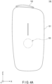
- FIG. 4A is a schematic front view of one example of the aerosol-generating device.
- FIG. 4B is a schematic top view of the aerosol-generating device shown in FIG. 4A .
- FIG. 4C is a schematic bottom view of the aerosol-generating device shown in FIG. 4A .
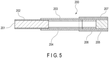
- FIG. 5 is a schematic sectional side view of one example of the flavor-generating article.
- FIG. 6 is a sectional view of the aerosol-generating device taken along the line III-III shown in FIG. 4B .
- the drawings may give an X-Y-Z orthogonal coordinate system for the sake of description.
- the Z axis is directed vertically upward
- the X-Y plane is disposed as if cutting the aerosol-generating device 100 in the horizontal direction
- the Y axis is disposed as if extending from the front surface to the rear surface of the aerosol-generating device 100.
- the Z axis may also be referred to as an insertion direction of the flavor-generating article for accommodation in a chamber 150 of a later-described atomization unit 130, or as an axial direction of the chamber 150.
- the X axis may be referred to as a direction orthogonal to the Y axis and the Z axis, and the X axis and the Y axis may each be referred to as a radial direction orthogonal to the axial direction of the chamber 150 or a radial direction of the chamber 150.
- the aerosol-generating device 100 is configured to generate flavor-containing aerosol by heating a stick-type flavor-generating article having a flavor source containing the above-described "flavor component adsorbent" or the above-described "flavor molded body".
- the aerosol-generating device 100 includes an outer housing 101 (corresponding to an example of a casing), a slide cover 102, and a switch part 103.
- the outer housing 101 constitutes the outermost housing of the aerosol-generating device 100 and has a size to fit in the hand of a user. For the user to use the flavor inhaler, the user can hold the aerosol-generating device 100 with their hand and inhale the aerosol.
- the outer housing 101 may be constituted by an assembly of multiple members.
- the outer housing 101 is, in one example, made of a resin such as, in particular, polycarbonate (PC), an acrylonitrile-butadiene-styrene (ABS) resin, polyether ether ketone (PEEK), or a polymer alloy containing multiple kinds of polymers, or may be made of a metal such as aluminum.
- a resin such as, in particular, polycarbonate (PC), an acrylonitrile-butadiene-styrene (ABS) resin, polyether ether ketone (PEEK), or a polymer alloy containing multiple kinds of polymers, or may be made of a metal such as aluminum.
- the switch part 103 is used to switch ON and OFF an operation of the aerosol-generating device 100.
- the user may operate the switch part 103 in a state where the flavor-generating article is inserted into the aerosol-generating device 100, and thereby electric power can be supplied from the power source (cf. reference sign 121 in FIG. 6 ) to a heater (cf. reference sign 140 in FIG. 6 ) to heat the flavor-generating article without burning it.
- the switch part 103 may be a switch provided outside the outer housing 101 or may be a switch located inside the outer housing 101. If the switch is located inside the outer housing 101, the switch is indirectly pressed down by the switch part 103 at the surface of the outer housing 101 being pressed down. For this example, the description will assume that the switch of the switch part 103 is located inside the outer housing 101.
- the aerosol-generating device 100 may further include a terminal (not shown in the figure).
- the terminal may be an interface for connecting the aerosol-generating device 100 to, for example, an external power source. If the aerosol-generating device 100 includes a rechargeable battery as its power source, an external power source may be connected to the terminal so that the external power source can flow current to the power source and charge the power source. Also, data associated with operations of the aerosol-generating device 100 may be transmitted to an external device through connection of the terminal with a data transmission cable.
- FIG. 5 is a schematic sectional side view of one example of the flavor-generating article 200.
- the flavor-generating article 200 includes a smokable material 201, a tubular member 204, a hollow filter portion 206, and a filter portion 205.
- the smokable material 201 is wrapped by a first wrapping paper 202.
- the tubular member 204, the hollow filter portion 206, and the filter portion 205 are wrapped by a second wrapping paper 203 differing from the first wrapping paper 202.
- the second wrapping paper 203 also wraps a part of the first wrapping paper 202 that wraps the smokable material 201. This couples the tubular member 204, the hollow filter portion 206, and the filter portion 205 to the smokable material 201.
- the second wrapping paper 203 may be omitted, and the tubular member 204, the hollow filter portion 206, and the filter portion 205 may be coupled to the smokable material 201 using the first wrapping paper 202.
- a lip release agent 207 for facilitating the separation of the lip of a user from the second wrapping paper 203 is applied to the outer surface of the second wrapping paper 203 around the end portion on the filter portion 205 side.
- the portion of the flavor-generating article 200 to which the lip release agent 207 is applied functions as a mouthpiece of the flavor-generating article 200.
- the smokable material 201 includes the above-described "flavor component adsorbent" or the above-described “flavor molded body” as a flavor source.
- the "flavor component adsorbent” and the “flavor molded body” may each be used as a flavor source of a heating-type flavor inhaler by itself, or may be used as a flavor source in combination with a tobacco filler generally employed for a heating-type flavor inhaler, as described above.
- the flavor molded body has a tablet shape
- a single piece of the flavor molded body may be used as a flavor source of a heating-type flavor inhaler, or multiple pieces of the flavor molded bodies may be used as a flavor source of a heating-type flavor inhaler.
- the product obtained by the molding may be used in its original size so as to serve as a flavor source of a heating-type flavor inhaler, or the sheet-shaped flavor molded body may be first cut into desirably sized pieces and used to serve as a flavor source of a heating-type flavor inhaler.
- the first wrapping paper 202 for wrapping the smokable material 201 may be an air-permeable sheet member.
- the tubular member 204 may be a paper pipe or a hollow filter.
- the flavor-generating article 200 includes the smokable material 201, the tubular member 204, the hollow filter portion 206, and the filter portion 205, but the flavor-generating article 200 is not limited to such a configuration.
- the hollow filter portion 206 may be omitted, and the tubular member 204 and the filter portion 205 may be disposed adjacent to each other.
- FIG. 6 is a sectional view of the aerosol-generating device 100 taken along the line III-III shown in FIG. 4B .
- an inner housing 110 (corresponding to an example of a casing) is provided inside the outer housing 101 of the aerosol-generating device 100.
- the inner housing 110 is, in one example, made of a resin such as, in particular, polycarbonate (PC), an acrylonitrile-butadiene-styrene (ABS) resin, polyether ether ketone (PEEK), or a polymer alloy containing multiple kinds of polymers, or may be made of a metal such as aluminum.
- the inner housing 110 is preferably made of PEEK from the viewpoint of heat resistance and strength.
- a power source unit 120 and the atomization unit 130 are provided in the internal space of the inner housing 110.
- the power source unit 120 includes a power source 121.
- the power source 121 may be, for example, a rechargeable battery or a non-rechargeable battery.
- the power source 121 is electrically connected to the atomization unit 130.
- the power source 121 is thus able to supply power to the atomization unit 130 so as to appropriately heat the flavor-generating article 200.
- the atomization unit 130 includes, as shown in FIG. 6 , a metal chamber 150 (corresponding to an example of a tubular portion) extending in the insertion direction of the flavor-generating article 200 (in the Z-axis direction), a heater 140 covering a part of the chamber 150, a heat-insulating portion 132, and a substantially tubular insertion guide member 134 (corresponding to an example of a guide portion) adjacent to an opening of the chamber 150.
- the chamber 150 is formed in such a configuration as to surround the periphery of the flavor-generating article 200.
- the heater 140 is formed to include a heating portion which contacts the outer circumferential surface of the chamber 150 and heats the flavor-generating article 200 inserted into the chamber 150.
- a bottom member 136 (corresponding to an example of an abutting portion) is provided at the bottom of the chamber 150.
- the bottom member 136 may function as a stopper for positioning the flavor-generating article 200, by abutting the flavor-generating article 200 inserted into the chamber 150 in the insertion direction of the flavor-generating article 200.
- the chamber 150 and the bottom member 136 constitute an accommodating portion for accommodating at least a part of the flavor-generating article 200.
- the bottom member 136 may be formed of, for example, a resin material.
- the bottom member 136 may have an irregularity in its surface that contacts the flavor-generating article 200, so that a first air flow path for supplying air to an air inlet of the flavor-generating article 200 (namely, an air flow path communicating with the flavor-generating article 200 accommodated in the accommodating portion) is defined.
- the bottom member 136 is, in one example, made of a resin such as, in particular, polycarbonate (PC), an acrylonitrile-butadiene-styrene (ABS) resin, polyether ether ketone (PEEK), or a polymer alloy containing multiple kinds of polymers, or may be made of a metal such as aluminum.
- the bottom member 136 is preferably made of a material with a low thermal conductivity in order to prevent heat from being transferred to the heat-insulating portion 132, etc.
- the heat-insulating portion 132 has a substantially tubular shape as a whole and is disposed to cover the chamber 150.
- the heat-insulating portion 132 may include, for example, an aerogel sheet.
- the insertion guide member 134 is provided between the slide cover 102 at the closed position and the chamber 150.
- the insertion guide member 134 is, in one example, made of a resin such as, in particular, polycarbonate (PC), an acrylonitrile-butadiene-styrene (ABS) resin, polyether ether ketone (PEEK), or a polymer alloy containing multiple kinds of polymers.
- the insertion guide member 134 may be formed of metal, glass, ceramic, or the like.
- the insertion guide member 134 is preferably made of PEEK.
- the insertion guide member 134 communicates with the outside of the aerosol-generating device 100 while the slide cover 102 is located at the open position, and guides the flavor-generating article 200 for insertion into the chamber 150 by inserting the flavor-generating article 200 into the insertion guide member 134. With the insertion guide member 134, easy insertion of the flavor-generating article 200 into the chamber 150 is enabled.
- the aerosol-generating device 100 further includes a first holding portion 137 and a second holding portion 138 for holding both ends of the chamber 150 and the heat-insulating portion 132.
- the first holding portion 137 is disposed so as to hold the end portions of the chamber 150 and the heat-insulating portion 132 on the z-axis negative direction side.
- the second holding portion 138 is disposed so as to hold the end portions of the chamber 150 and the heat-insulating portion 132 on the slide cover 102 side (on the Z-axis positive direction side).
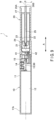
- FIG. 7 is a perspective view showing an example of the heat-not-burn flavor inhaler.
- FIG. 8 is a perspective view of a power supply unit in the heat-not-burn flavor inhaler shown in FIG. 7 .
- FIG. 9 is a sectional view of the heat-not-burn flavor inhaler shown in FIG. 7 .
- FIG. 10 is a block diagram showing a configuration of the main part of the power supply unit in the heat-not-burn flavor inhaler shown in FIG. 7 .
- This heat-not-burn flavor inhaler 1 (which may be simply called a "heating-type flavor inhaler 1" below) shown in FIGS. 7 to 10 has a rod shape extending along a predetermined direction (hereinafter referred to as a longitudinal direction A).
- the heating-type flavor inhaler 1 includes, as shown in FIG. 7 , a power supply unit 10 and a cartridge 20 in this order along the longitudinal direction A.
- the cartridge 20 is detachable from the power supply unit 10. In other words, the cartridge 20 is replaceable.
- the power supply unit 10 accommodates, as shown in FIGS. 8 and 9 , a power supply 12, a charger 13, a control part 50, various sensors, etc., inside a cylindrical power supply unit case 11.
- the power supply 12 is a rechargeable secondary battery which is preferably a lithium ion secondary battery.
- a discharge terminal 41 is provided at a top portion 11a located on one end side in the longitudinal direction A (i.e., the cartridge 20 side) of the power supply unit case 11.
- the discharge terminal 41 is provided in such a form as to protrude from the upper surface of the top portion 11a toward the cartridge 20 and is configured to be electrically connectable to a load 21 in the cartridge 20.
- an air supply part 42 for supplying air to the load 21 in the cartridge 20 is provided in the vicinity of the discharge terminal 41.
- a charge terminal (not shown in the figure) electrically connectable to an external power source that can charge the power supply 12 is provided at a bottom portion 11b located on the other end side in the longitudinal direction A (the side opposite to the cartridge 20) of the power supply unit case 11.
- a user-operable operation part 14 is provided at the side surface of the top portion 11a of the power supply unit case 11.
- the operation part 14 is constituted by a button switch, a touch panel, or the like, and is used for activating/shutting off the control part 50 and the various sensors in response to user's intentions for use.
- the control part 50 is, as shown in FIG. 10 , connected to the charger 13, the operation part 14, various sensor devices such as an inhalation sensor 15 for detecting a puff (inhalation) action, a voltage sensor 16 for measuring a voltage of the power supply 12, and a temperature sensor 17 for detecting a temperature, and a memory 18 for storing the number of puff actions, the time of current application to the load 21, etc., and is adapted to perform various controls for the heating-type flavor inhaler 1.
- the inhalation sensor 15 may be constituted by a condenser microphone, a pressure sensor, etc.
- a concrete form of the control part 50 is a processor (micro-controller unit (MCU)).
- MCU micro-controller unit
- the structure of this processor is, in more concrete terms, electric circuitry formed of a combination of circuit elements such as semiconductor elements.
- the cartridge 20 includes, inside a cylindrical cartridge case 27, a reservoir 23 for retaining a liquid aerosol source 22, the electric load 21 for atomizing the aerosol source 22, a wick 24 for drawing the aerosol source from the reservoir 23 to the load 21, and an aerosol flow path 25 for the aerosol generated by the atomization of the aerosol source 22 to flow toward a mouthpiece 26A.
- the reservoir 23 is delimited so as to surround the aerosol flow path 25 and retains the liquid aerosol source 22.
- the aerosol source is a liquid for forming aerosol. Examples that may be employed as the aerosol source include propylene glycol, glycerin, 1,3-propanediol, diacetin, polyethylene glycol, or any mixture thereof.
- the reservoir 23 may enclose a porous member such as a resin web or cotton, into which the aerosol source 22 may be impregnated.
- the reservoir 23 may keep only the aerosol source 22 without enclosing a porous member such as a resin web or cotton.
- the reservoir 23 may contain a tobacco flavored liquid, an additional flavoring component (e.g., nicotine, a flavorant, etc.), and so on, in addition to the aerosol source 22.
- Example 1 effects of the flavor component adsorbent and the flavor molded body each serving as a flavor source were checked.
- Cut tobacco was coarsely crushed to obtain coarsely crushed tobacco having a size of 1.00 to 3.35 mm.
- Glycerin was added to the coarsely crushed tobacco in an amount of 10 mass% based on the coarsely crushed tobacco.
- 20 g of the obtained coarsely crushed tobacco were heated at 180 °C for 30 minutes using a heating device as shown in FIG. 2 .
- a "flavor component-containing gas" was thus generated.
- Example 2 comparison was made between a case of using water and a case of using polyethylene glycol as a trapping solvent for preparing the flavor component adsorbent.
- flavor component adsorbent was prepared in the same manner as in Example 1. This will be called a flavor component adsorbent 2A.
- flavor component adsorbent was prepared in the same manner as in Example 1, except that bubbling of the flavor component-containing gas was done in polyethylene glycol and the polyethylene glycol was removed by a centrifugal separator using a cell strainer, followed by 30-minute drying in a dryer set at 100 °C. This will be called a flavor component adsorbent 2B.
- a tablet-shaped flavor molded body was prepared in the same compression molding manner as in Example 1.
- the flavor molded body prepared using the flavor component adsorbent 2A will be called a flavor molded body 2A.
- the flavor molded body prepared using the flavor component adsorbent 2B will be called a flavor molded body 2B.
- the characteristic flavor and taste of a tobacco distillate (namely, a complex flavor where a burnt sweet scent and a green herbal note coexist) were strongly sensed since about the initial puff. The flavor lasted until about the 5th to 8th puff. The flavor became weak from the 10th puff, but the characteristics were recognizable.
- the characteristic flavor of a tobacco distillate was faintly sensed at the first puff.
- the faint sensing of the characteristic flavor also lasted after the 2nd puff as well, but only for a "burnt" portion of the characteristic flavor of the tobacco distillate.
Landscapes
- Chemical & Material Sciences (AREA)
- Chemical Kinetics & Catalysis (AREA)
- General Chemical & Material Sciences (AREA)
- Manufacture Of Tobacco Products (AREA)
Abstract
Description
- The present invention relates to a flavor component adsorbent and a method for producing the same, a flavor molded body and a method for producing the same, a heat-not-burn flavor inhaler, and a flavor-generating article.
- Obtaining a flavor component-containing liquid by heating a tobacco material and dissolving a thus-generated flavor component-containing gas in a liquid, and using such a flavor component-containing liquid as a tobacco flavor source in a flavor inhaler have been known (see, for example, Patent Document 1).
- Patent Document 1: International Publication No.
2017/144705 - Objects of the present invention include providing a technique for efficiently recovering flavor components from a tobacco material.
- According to one aspect, there is provided a method for producing a flavor component adsorbent, comprising:
- heating a tobacco material to vaporize flavor components from the tobacco material;
- passing a gas containing the flavor components through water containing an adsorbent to adsorb the flavor components on the adsorbent; and
- recovering the adsorbent that has adsorbed the flavor components.
- According to another aspect, there is provided a flavor component adsorbent obtainable by the above-mentioned method.
- According to further another aspect, there is provided a method for producing a flavor molded body, comprising:
- heating a tobacco material to vaporize flavor components from the tobacco material;
- passing a gas containing the flavor components through water containing an adsorbent to adsorb the flavor components on the adsorbent;
- recovering the adsorbent that has adsorbed the flavor components to obtain a flavor component adsorbent; and
- mixing the flavor component adsorbent with a molding material and molding an obtained mixture.
- According to further another aspect, there is provided a flavor molded body obtainable by the above-mentioned method.
- According to further another aspect, there is provided a heat-not-burn flavor inhaler comprising:
- a flavor source containing the above-mentioned flavor component adsorbent or the above-mentioned flavor molded body; and
- a heater for heating the flavor source.
- According to further another aspect, there is provided a flavor-generating article comprising:
- a flavor source containing the above-mentioned flavor component adsorbent or the above-mentioned flavor molded body; and
- a wrapping paper wrapped around the flavor source.
- According to the present invention, a technique for efficiently recovering flavor components from a tobacco material is provided.
-
-
FIG. 1 is a flowchart showing an exemplary production method for a flavor component adsorbent. -
FIG. 2 is a schematic diagram showing an exemplary heating device. -
FIG. 3 is a schematic diagram showing an exemplary dissolving device. -
FIG. 4A is a schematic front view showing an exemplary aerosol-generating device. -
FIG. 4B is a schematic top view of the aerosol-generating device shown inFIG. 4A . -
FIG. 4C is a schematic bottom view of the aerosol-generating device shown inFIG. 4A . -
FIG. 5 is a schematic sectional side view showing an exemplary flavor-generating article. -
FIG. 6 is a sectional view of the aerosol-generating device taken along the line III-III shown inFIG. 4B . -
FIG. 7 is a perspective view showing an exemplary heat-not-burn flavor inhaler. -
FIG. 8 is a perspective view of a power supply unit in the heat-not-burn flavor inhaler shown inFIG. 7 . -
FIG. 9 is a sectional view of the heat-not-burn flavor inhaler shown inFIG. 7 . -
FIG. 10 is a block diagram showing a configuration of the main part of the power supply unit in the heat-not-burn flavor inhaler shown inFIG. 7 . - The present invention will be described in detail with the intention of allowing the invention to be understood, not limiting the invention.
- A method for producing a flavor component adsorbent includes:
- heating a tobacco material to vaporize flavor components from the tobacco material;
- passing a gas containing the flavor components through water containing an adsorbent to adsorb the flavor components on the adsorbent; and
- recovering the adsorbent that has adsorbed the flavor components.
- In the present disclosure, the "adsorbent that has adsorbed the flavor components" produced by this method is referred to as a flavor component adsorbent. The flavor component adsorbent may be used in such a manner that it is incorporated into a heat-not-burn flavor inhaler (which may also be simply called a "heating-type flavor inhaler" below) as it is, or that it is processed into a molded body together with a molding material and then the obtained molded body is incorporated into a heating-type flavor inhaler.
- The method for producing a flavor component adsorbent will be described with reference to
FIG. 1 , in the order of a [heating step (S1)], an [adsorbent-containing water passing through step (S2)], and a [recovering step (S3)].FIG. 1 shows, in the form of a flowchart, one example of the method for producing a flavor component adsorbent. - The heating step (S1) heats a tobacco material to vaporize flavor components from the tobacco material. By the heating step (S1), a gas containing the flavor components is obtained (see
FIG. 1 ). - As the "tobacco material", cut tobacco which is ready to be incorporated into a tobacco product, such as a combustiontype or heating-type flavor inhaler, may be used. The "cut tobacco which is ready to be incorporated into a tobacco product" refers to cut tobacco which has become ready to be incorporated into a tobacco product by going through various processes including drying in a farm house, subsequent long-term aging in a leaf processing facility for one to several years, and subsequent blending and cutting in a manufacturing facility.
- The cut tobacco consists of cut pieces of leaf tobacco. The cut tobacco may be any of cut pieces of stemmed leaves, cut pieces of midrib, and cut pieces of reconstituted tobacco (i.e., a tobacco material obtained by processing leaf scraps, cut tobacco scraps, midrib scraps, fine powder, etc., produced in the facility processes into a reusable form), or a mixture thereof. The cut tobacco may be pulverized and the resulting pulverized product may be applied to the heating step (S1). Use of the pulverized product of the cut tobacco as a tobacco material can realize an enhanced efficiency in recovery of flavor components from the tobacco material. This can increase the amount of adsorbed flavor components in the eventually obtained flavor component adsorbent.
- As the cut tobacco, cut tobacco derived from any tobacco variety may be used, and its examples include cut tobacco derived from flue-cured tobacco, Burley tobacco, Oriental tobacco, etc. As the cut tobacco, cut tobacco derived from a single variety, or a mixture of different varieties may be used.
- The heating may be conducted at a temperature of, for example, 120 to 400 °C, preferably 160 to 230 °C. The heating may be conducted for a period of, for example, 5 to 60 minutes, preferably 10 to 30 minutes.
- For example, the heating may be conducted using a heating apparatus shown in
FIG. 2 . As shown inFIG. 2 , thisheating device 2 includes acontainer 2A for accommodating atobacco material 2D, asintered plate 2B arranged at the bottom of thecontainer 2A, apreheater 2C for heating air sent to thecontainer 2A, anair flow path 2E for sending air to thecontainer 2A, agas flow path 2F for discharging a gas generated by heating thetobacco material 2D from thecontainer 2A, and an oven (not shown in the figure) for accommodating thecontainer 2A. - A heating operation will be described. First, the
tobacco material 2D is put in thecontainer 2A. Air is heated by thepreheater 2C and then sent through theair flow path 2E to a gas inlet provided at the bottom of thecontainer 2A. Thesintered plate 2B arranged at the bottom of thecontainer 2A is a porous member. Accordingly, the high-temperature air entering thecontainer 2A from the gas inlet is supplied throughout thetobacco material 2D via thesintered plate 2B. Thetobacco material 2D is heated by the supplied high-temperature air. - The
container 2A is accommodated in the oven (not shown in the figure). Thus, thetobacco material 2D is also heated from outside thecontainer 2A. - By heating the
tobacco material 2D in this manner, a flavor component-containing gas is generated from thetobacco material 2D and discharged from a gas outlet provided at the top of thecontainer 2A and through thegas flow path 2F. - It is possible to change the composition of the flavor component-containing gas by changing the concentration of oxygen in the air sent to the
container 2A. Thus, the oxygen concentration in the air sent to thecontainer 2A may be controlled so as to change the composition of the flavor component-containing gas. As one example, lowering the oxygen concentration in the air can reduce the content of harmful components in the flavor component-containing gas. - Note that the heating step is not limited to the use of the heating device shown in
FIG. 2 as long as the flavor components are successfully vaporized from the tobacco material. - With the heating step described above, a flavor component-containing gas is obtained.
- The adsorbent-containing water passing through step (S2) causes the flavor component-containing gas obtained in the heating step (S1) to pass through water which contains an adsorbent so that the flavor components are adsorbed on the adsorbent. By this, water containing the adsorbent that has adsorbed the flavor components (i.e., the flavor component adsorbent) is obtained (see
FIG. 1 ). - The adsorbent used in this step is preferably a porous material. The porous material refers to a material which has a large number of fine-sized holes (i.e., pores). As the porous material, a material having a wide pore distribution from micro-pores (d < 2 nm) to meso-pores (2 nm ≤ d ≤ 50 nm) and even to macro-pores (50 nm < d), that is, a material having pores of various sizes including micro-pores, meso-pores, and macro-pores is preferable. Pore sizes of porous materials are known to show a correlation with molecular weights of molecules that can be adsorbed. Thus, a porous material showing a wide pore distribution is capable of adsorbing, into its pores, flavor components of various molecular sizes which have been derived from the tobacco material.
- The adsorbent may have any form, for example, a particulate form, a sheet form, or a fiber form. The adsorbent is preferably in the form of particles. The adsorbent is more preferably a porous material which has a form of particles. In other words, the adsorbent is more preferably porous particles. The particle size of the adsorbent particles may be determined in consideration of the application to a flavor inhaler, convenience in handling, processability into a molded body, etc. In one example, the adsorbent particles each have a particle size of 200 to 1000 µm.
- The porous material preferably has a total pore volume of 0.2 to 3.0 mL/g. The porous material more preferably has a total pore volume of 0.4 to 1.5 mL/g. It is also preferable that the porous material include all of the micro-pores (d < 2 nm), meso-pores (2 nm ≤ d ≤ 50 nm), and macro-pores (50 nm < d). The pore volume here refers to a value obtained by measurement according to JIS Z8831-2:2010 and JIS Z8831-3:2010. The porous material also preferably has a BET specific surface area of 500 to 2000 m2/g. The porous material more preferably has a BET specific surface area of 550 to 1000 m2/g. The BET specific surface area here refers to a value obtained by measurement according to JIS Z8830:2013.
- Examples of the porous material include activated carbon, activated alumina, a synthetic adsorbent, and zeolite. The porous material is preferably activated carbon. The activated carbon is capable of adsorbing, into its pores, flavor components of various molecular sizes which have been derived from the tobacco material. One type of the porous material or a combination of two or more types of the porous materials differing in pore properties may be employed.
- The activated carbon may have any form, for example, a particulate form, a sheet form, or a fiber form. The activated carbon is preferably in the form of particles. In other words, the adsorbent is preferably activated carbon particles. The activated carbon particles are also called granular activated carbon, which may include crushed activated carbon and granulated activated carbon. In one example, the activated carbon particles each have a particle size of 200 to 1000 µm.
- The adsorbent may be settled or suspended in water. In this step, water serves to allow the flavor components derived from the tobacco material to be efficiently adsorbed onto the adsorbent through dissolution in the water, without releasing the flavor components into the atmosphere. That is, the water serves as a trapping solvent to temporarily trap the flavor components derived from the tobacco material. The water here is not particularly limited, and any of tap water, ion-exchanged water, distilled water, etc. may be used.
- In this step, the mass ratio between the adsorbent and the water may be set to, for example, 1:0.5 to 1:20, preferably 1:2 to 1:5.
- A description will be given of reasons why water serves as a good trapping solvent.
- The adsorbent such as activated carbon is contained in water in this step, but has a non-polar nature, and as such, it hardly adsorbs the water, which is a polar molecule. Thus, use of water as a trapping solvent hardly causes the adsorbent to adsorb water before adsorbing the flavor components derived from the tobacco material, such that the adsorption of the flavor components derived from the tobacco material would not be disturbed. Also, many of the flavor components derived from the tobacco material are non-polar, and as such, they are energetically more stable in the state of being adsorbed on the adsorbent than in the state of being dissolved in water. Accordingly, once adsorbed onto the adsorbent through dissolution in water, the flavor components derived from the tobacco material are stably maintained in the adsorbed state on the adsorbent. For these reasons water is a good trapping solvent.
- Meanwhile, it might be another option to use, as a trapping solvent, a solvent generally employed as an aerosol source for a heating-type flavor inhaler (e.g., polyethylene glycol or glycerin), ethanol which is described in the prior art document (International Publication No. 2017/144705), or the like. However, use of polyethylene glycol or glycerin as a trapping solvent would cause the adsorbent such as activated carbon to adsorb such a liquid before adsorbing the flavor components derived from the tobacco material, which renders impossible the sufficient adsorption of the flavor components derived from the tobacco material (see later described Example 2). Also, in the case of using ethanol as a trapping solvent, the flavor components derived from the tobacco material cannot be sufficiently adsorbed onto the adsorbent since the flavor components derived from the tobacco material are energetically more stable in the state of being dissolved in ethanol than in the state of being adsorbed on the adsorbent. These solvents are therefore not suitable as a trapping solvent.
- The passing through step (S2) may preferably be conducted by causing bubbling in the adsorbent-containing water with the flavor component-containing gas obtained in the heating step (S1). In the passing through step (S2), for example, water may be used in an amount of 3 to 20 mL per 10 g of the tobacco material.
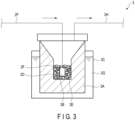
- The passing through step (S2) may be conducted using a device which collects a gas by dissolving it in a liquid. In one example, this step may be conducted using a dissolving device shown in
FIG. 3 . Thisdissolving device 3 shown inFIG. 3 is connected to the heating device shown inFIG. 2 via thegas flow path 2F. As shown inFIG. 3 , thedissolving device 3 includes aninner container 3A for accommodatingwater 3E containing an adsorbent 3D, asintered filter 3B as a bubbling nozzle, anouter container 3C for accommodating theinner container 3A, thegas flow path 2F for sending the flavor component-containing gas to theinner container 3A, and a dischargegas flow path 3H for discharging the gas present within theinner container 3A. - An adsorbing operation realized through dissolution in water will be described. The flavor component-containing gas obtained in the heating step (S1) is sent through the
gas flow path 2F to thesintered filter 3B arranged at the end of thegas flow path 2F. Thesintered filter 3B has a porous structure and is immersed in thewater 3E containing the adsorbent 3D. The flavor component-containing gas thus causes bubbling in thewater 3E containing the adsorbent 3D. The flavor component-containing gas is accordingly dissolved in thewater 3E and adsorbed onto the adsorbent 3D contained in thewater 3E. - The
inner container 3A accommodatesglass beads 3F in addition to the adsorbent 3D and thewater 3E. Conducting the bubbling under the presence of theglass beads 3F allows the flavor components to be more efficiently trapped in thewater 3E and adsorbed onto the adsorbent 3D. - Bubbling of the
water 3E with the flavor component-containing gas increases the temperature of thewater 3E. To cope with this,ice water 3G is accommodated in theouter container 3C. This can prevent a temperature rise of thewater 3E. The gas generated within theinner container 3A is discharged through the dischargegas flow path 3H. - Note that the passing through step (S2) is not limited to the use of the dissolving device shown in
FIG. 3 as long as the flavor component-containing gas obtained in the heating step is successfully adsorbed onto the adsorbent through dissolution in water. - With the passing through step described above, the flavor component-containing gas is adsorbed onto the adsorbent. Accordingly, water containing the adsorbent that has adsorbed the flavor components (i.e., the flavor component adsorbent) is obtained.
- The recovering step (S3) recovers the flavor component adsorbent from the "water containing the adsorbent that has adsorbed the flavor components (i.e., the flavor component adsorbent)" obtained in the foregoing passing through step (S2) (see
FIG. 1 ). - For example, the recovery may be conducted by suctioning water from the water containing the flavor component adsorbent, or by allowing the water containing the flavor component adsorbent to pass through a filtering member such as a filter or a sieve.
- After the recovery, the flavor component adsorbent may be dried. Drying the flavor component adsorbent enables removal of water remaining on the surface of the flavor component adsorbent. This prevents the flavor component adsorbent from causing aggregation so that its ease of handling can be enhanced. The drying may be conducted by blowing air onto the flavor component adsorbent at room temperature (e.g., a temperature of 15 to 25 °C), or by subjecting the flavor component adsorbent to heat drying. The heat drying may be conducted by, for example, applying heat with a heater or blowing heated air. If the heat drying is adopted, the drying may be conducted at a temperature of, for example, 50 to 100 °C. Heating at such a temperature can obviate desorption of the flavor components that have been adsorbed onto the adsorbent from the adsorbent.
- The foregoing method may further include, between the passing through step (S2) and the recovering step (S3), cooling the water containing the adsorbent that has adsorbed the flavor components (i.e., the flavor component adsorbent).
- For example, the cooling may be conducted by keeping the water containing the flavor component adsorbent stationary at a temperature of 0 to 30 °C for a period of 0.1 to 72 hours. The cooling temperature may preferably be set to 0 to 10 °C, and the cooling time may preferably be set to 6 to 48 hours. By cooling the water containing the flavor component adsorbent at the timing between the passing through step (S2) and the recovering step (S3), the adsorbent that has adsorbed the flavor components can be encouraged to further adsorb the flavor components.
- The foregoing method may further include a step of adding a liquid which serves as an aerosol source to the tobacco material prior to the heating step (S1).
- As used herein, the term "aerosol source" refers to a source (liquid) for generating vapor (gas) when heated by a heating-type flavor inhaler. The term "aerosol source" refers to a source (liquid) for generating a dispersion medium (gas) for aerosol (tobacco vapor), and does not include fine particles (such as flavor components) in the aerosol.
- Adding a liquid serving as an aerosol source to the tobacco material prior to the heating step (S1) facilitates the vaporization of the flavor components from the tobacco material during the heating step (s1), which can enhance the efficiency in recovery of the flavor components from the tobacco material. This can increase the amount of adsorbed flavor components in the eventually obtained flavor component adsorbent.
- As the aerosol source, a liquid usable as an aerosol source in a heating-type flavor inhaler may be used. For example, propylene glycol, glycerin, 1,3-propanediol, diacetin, polyethylene glycol, or any mixture thereof may be used. Preferably, the aerosol source is propylene glycol, glycerin, or a mixture of propylene glycol and glycerin. For the case of adopting the mixture of propylene glycol and glycerin, the mass ratio between propylene glycol and glycerin is not particularly limited and may be set to, for example, 0.1 : 9.9 to 9.9 : 0.1.
- The liquid mentioned for the exemplary purpose has a lower polarity than water, and the flavor components have a relatively low polarity. Thus, the exemplary liquid is suitable as a liquid for facilitating the vaporization of the flavor components from the tobacco material. For example, the aerosol source may be added in an amount of 0.1 to 20 mL per 10 g of the tobacco material.
- By heating the tobacco material and then passing the thus-obtained gas through the water containing the adsorbent in accordance with the method of the present invention, it is possible to dissolve the gas in the water without having it released into the atmosphere, and to subsequently adsorb, onto the adsorbent present in the water, the flavor components contained in the gas dissolved in the water. As such, the method of the present invention can efficiently adsorb the flavor components derived from the tobacco material onto the adsorbent through dissolution in water, without releasing the flavor components into the atmosphere. Also, the flavor components derived from the tobacco material are, once adsorbed onto the adsorbent, hardly dissolved in water again and they can stably maintain their adsorbed state.
- Since the method of the present invention can recover the flavor components from the tobacco material with high recovery efficiency as discussed above, the flavor component adsorbent obtained by the method of the present invention can contain an abundant amount of the flavor components derived from the tobacco material.
- Additionally, the method of the present invention is superior to the gas-phase adsorption and the liquid-phase adsorption described in the prior art document (International Publication No. 2017/144705) in the following respects.
- The prior art document (International Publication No. 2017/144705) discloses directly adsorbing volatiles generated by heating a tobacco material onto adsorbents (i.e., gas-phase adsorption). Such gas-phase adsorption is considered to require a large amount of adsorbents in order to adsorb the volatiles generated by heating the tobacco material only in the gas phase. In contrast, by first trapping the gas generated by heating a tobacco material in water as in the present invention, the flavor components trapped by the water can be efficiently recovered without using a large amount of adsorbents.
- Also, supposing that the gas-phase adsorption is conducted using an adsorbent particle-filled column, it is expected that the adsorbent particles located near the column inlet would adsorb the flavor components at a particularly high concentration, and the adsorbent particles finally recovered would then involve non-uniform adsorption results. Further in this case, heating the tobacco material produces "tar" (which refers to a viscous substance in smoke generated from the burnt tobacco material), and there is even a risk of tar clogging at the column inlet. In contrast, the method of the present invention is free from the occurrence of problems such as non-uniform flavor-component adsorption results and tar clogging.
- The prior art document (International Publication No. 2017/144705) also discloses dissolving volatiles generated by heating a tobacco material in a liquid (i.e., liquid-phase adsorption). Such liquid-phase adsorption provides a flavor liquid in which flavor components are dissolved. Normally, this flavor liquid needs to be concentrated in order to be incorporated into a flavor inhaler in the liquid form, and the concentrating is conducted by subjecting the flavor liquid to a drying process utilizing reduced-pressure heating or the like. The concentrating is carried out by heating the flavor liquid at a temperature of approximately 40 to 100 °C under reduced pressure, but this process would force the flavor components in the flavor liquid to volatilize.
- As another option, it is possible to pour the flavor liquid obtained by the liquid-phase adsorption back into the tobacco residue, mold the obtained mixture, and incorporate it into a flavor inhaler. This option incurs the necessity of concentrating the flavor liquid before pouring it back into the tobacco residue, and the necessity of conducting drying to remove water added for the molding. The concentrating is carried out by heating the flavor liquid at a temperature of approximately 40 to 100°C. Also, the drying for the removal of water is carried out through heating at a temperature of about 70 to 120 °C. These processes would likewise volatilize the flavor components in the flavor liquid.
- In contrast, according to the method of the present invention, the flavor components derived from the tobacco material are, in their final state, adsorbed on the adsorbent and do not remain in water. Therefore, no heating for the purpose of concentrating the solvent is required after recovery of the adsorbent that has adsorbed the flavor components. As described above, the recovered adsorbent may be subjected to heat-drying at a temperature of approximately 50 to 100 °C in order to remove moisture on the surface, but the heating at such a temperature would hardly volatilize the flavor components adsorbed on the adsorbent. This is because the volatilization of components adsorbed on the adsorbent must give the adsorbed components not only "energy for volatilizing" but also "energy for escaping from the state of being adsorbed on the adsorbent". That is, in order to volatilize the components adsorbed on the adsorbent by heating, application of heat (energy) which is higher than that for volatilizing the same components not adsorbed on the adsorbent is required.
- Therefore, the flavor component adsorbent obtained by the method of the present invention does not cause volatilization of the flavor components unless it is heated at a temperature higher than the heating temperature that causes volatilization of the flavor components in the case of a flavor liquid obtained by the liquid-phase adsorption. It should be noted that the flavor component adsorbent obtained by the method of the present invention is, after incorporation into a heating-type flavor inhaler, heated at a high temperature of approximately 150 to 400 °C, and accordingly, the flavor components adsorbed on the adsorbent will be easily released.
- According to another aspect, a flavor component adsorbent obtained by the above-described "method for producing a flavor component adsorbent" is provided. The flavor component adsorbent is, as is apparent from its production method, constituted by an adsorbent and flavor components adsorbed on the adsorbent. The flavor component adsorbent may have any form, for example, a particulate form, a sheet form, or a fiber form, as in the case of the adsorbent. The flavor component adsorbent preferably has a particulate form. The flavor component adsorbent in the particulate form has a particle size of, for example, 200 to 1000 µm.
- The flavor component adsorbent may be used as a flavor source of a heating-type flavor inhaler by itself, or may be used as a flavor source in combination with a tobacco filler generally employed for a heating-type flavor inhaler.
- As described above, since the method of the present invention can recover the flavor components from the tobacco material with high recovery efficiency, the flavor component adsorbent obtained by the method of the present invention can contain an abundant amount of the flavor components derived from the tobacco material. Therefore, incorporating such a flavor component adsorbent into a heating-type flavor inhaler can provide an excellent smoking flavor to a user.
- The flavor component adsorbent described above may be used in such a manner that it is incorporated into a heating-type flavor inhaler as it is, or that it is processed into a molded body together with a molding material and then the obtained molded body is incorporated into a heating-type flavor inhaler.
- Thus, according to another aspect, a flavor molded body containing the above-described flavor component adsorbent and a molding material is provided.
- According to still another aspect, there is provided a method for producing a flavor molded body, the method including mixing the above-described flavor component adsorbent with a molding material and molding the obtained mixture. More specifically, a method for producing a flavor molded body includes:
- heating a tobacco material to vaporize flavor components from the tobacco material;
- passing a gas containing the flavor components through water containing an adsorbent to adsorb the flavor components on the adsorbent;
- recovering the adsorbent that has adsorbed the flavor components to obtain a flavor component adsorbent; and
- mixing the flavor component adsorbent with a molding material and molding the obtained mixture.
- According to still another aspect, a flavor molded body obtained by the above method is provided.
- Molding the above-described flavor component adsorbent into a desired shape can enhance its ease of handling for incorporation into a heating-type flavor inhaler. Also, molding the above-described flavor component adsorbent into a desired shape can prevent the flavor component adsorbent from easily dropping off from a heating-type flavor inhaler after incorporation into the heating-type flavor inhaler.
- The flavor molded body may be formed into any shape, and examples of such possible shapes include a tablet shape, a sheet shape, a granular shape, and a fiber shape. As the flavor molded body, the product obtained by the molding may be used in its original size so as to serve as a flavor source of a heating-type flavor inhaler, or the product obtained by the molding may be first cut into desirably sized pieces and used to serve as a flavor source of a heating-type flavor inhaler.
- Also, the flavor molded body may be used as a flavor source of a heating-type flavor inhaler by itself, or may be used as a flavor source in combination with a tobacco filler generally employed for a heating-type flavor inhaler.
- According to one example, the flavor molded body may be produced by mixing the above-described flavor component adsorbent with cellulose powder and alcohol having 2 to 7 carbon atoms (e.g., ethanol), compression-molding the obtained mixture into a tablet shape (i.e., a flat cylindrical shape), and drying the resultant at room temperature (e.g., 20 °C). Instead of cellulose powder, tobacco fine powder may be employed as a binder in this example. As the cellulose powder or the tobacco fine powder, powder having an average particle size of, for example, 10 to 200 µm may be employed. A single piece of the tablet-shaped flavor molded body may be used as a flavor source of a heating-type flavor inhaler, or multiple pieces of the tablet-shaped flavor molded bodies may be used as a flavor source of a heating-type flavor inhaler.
- According to another example, the flavor molded body may be produced by mixing the above-described flavor component adsorbent with cellulose powder, an additional binder (e.g., guar gum), and water, molding the obtained mixture into a sheet shape, and heat-drying the resultant. Also in this example, tobacco fine powder may be employed as a binder, instead of cellulose powder. As the cellulose powder or the tobacco fine powder, powder having an average particle size of, for example, 10 to 200 µm may be employed. As the sheet-shaped flavor molded body, the product obtained by the molding may be used in its original size so as to serve as a flavor source of a heating-type flavor inhaler, or the sheet-shaped flavor molded body may be first cut into desirably sized pieces and used to serve as a flavor source of a heating-type flavor inhaler.
- The above-described flavor component adsorbent can contain an abundant amount of the flavor components derived from the tobacco material. Therefore, producing a flavor molded body using the above-described flavor component adsorbent and incorporating this flavor molded body into a heating-type flavor inhaler can provide an excellent smoking flavor to a user.
- The above-described "flavor component adsorbent" or the above-described "flavor molded body" may be incorporated into any heat-not-burn flavor inhaler. That is, according to another aspect, there is provided a heat-not-burn flavor inhaler including a flavor source containing the above-described "flavor component adsorbent" and a heater for heating the flavor source. According to still another aspect, there is provided a heat-not-burn flavor inhaler including a flavor source containing the above-described "flavor molded body" and a heater for heating the flavor source.
- A heat-not-burn flavor inhaler refers to a flavor inhaler which provides a tobacco flavor to a user by heating a flavor source such as a tobacco filler or a tobacco flavored liquid without burning the flavor source. In this disclosure, a heat-not-burn flavor inhaler may also be simply called a "heating-type flavor inhaler". Examples of such a heating-type flavor inhaler include:
- a carbon heat source-type flavor inhaler which heats a tobacco filler with combustion heat of a carbon heat source (see, for example,
WO 2006/073065 ); - an electric heating-type flavor inhaler which includes a tobacco stick containing a tobacco filler and a heating device for electrically heating the tobacco stick (see, for example,
WO 20101110226 - a liquid atomizing-type flavor inhaler which heats a liquid aerosol source with a heater to generate aerosol and permits a flavor from a tobacco filler to be inhaled together with the aerosol (see, for example,
WO 2015/046385 ). - According to a preferred first embodiment, there is provided a heat-not-burn flavor inhaler including:
- a flavor-generating article including: a flavor source containing the above-described "flavor component adsorbent" or the above-described "flavor molded body", and a wrapping paper wrapped around the flavor source; and
- a heater for heating the flavor source included in the flavor-generating article.
- According to a preferred second embodiment, there is provided a heat-not-burn flavor inhaler including:
- a flavor source containing the above-described "flavor component adsorbent" or the above-described "flavor molded body";
- a liquid storage portion for storing a liquid aerosol source to be supplied to the flavor source; and
- a heater for heating the flavor source to which the aerosol source has been supplied, atomizing the aerosol source and releasing the flavor components from the flavor source.
- An example of the heat-not-burn flavor inhaler according to the first embodiment and an example of the heat-not-burn flavor inhaler according to the second embodiment will be described with reference to the drawings.
- An example of the heat-not-burn flavor inhaler according to the first embodiment will be described with reference to
FIGS. 4A ,4B ,4C ,5 , and6 . In this example, a heat-not-burn flavor inhaler is constituted by an aerosol-generatingdevice 100 and a flavor-generatingarticle 200.FIG. 4A is a schematic front view of one example of the aerosol-generating device.FIG. 4B is a schematic top view of the aerosol-generating device shown inFIG. 4A .FIG. 4C is a schematic bottom view of the aerosol-generating device shown inFIG. 4A .FIG. 5 is a schematic sectional side view of one example of the flavor-generating article.FIG. 6 is a sectional view of the aerosol-generating device taken along the line III-III shown inFIG. 4B . - The drawings may give an X-Y-Z orthogonal coordinate system for the sake of description. In this coordinate system, the Z axis is directed vertically upward, the X-Y plane is disposed as if cutting the aerosol-generating
device 100 in the horizontal direction, and the Y axis is disposed as if extending from the front surface to the rear surface of the aerosol-generatingdevice 100. The Z axis may also be referred to as an insertion direction of the flavor-generating article for accommodation in achamber 150 of a later-describedatomization unit 130, or as an axial direction of thechamber 150. Also, the X axis may be referred to as a direction orthogonal to the Y axis and the Z axis, and the X axis and the Y axis may each be referred to as a radial direction orthogonal to the axial direction of thechamber 150 or a radial direction of thechamber 150. - The aerosol-generating
device 100 is configured to generate flavor-containing aerosol by heating a stick-type flavor-generating article having a flavor source containing the above-described "flavor component adsorbent" or the above-described "flavor molded body". - As shown in
FIGS. 4A to 4C , the aerosol-generatingdevice 100 includes an outer housing 101 (corresponding to an example of a casing), aslide cover 102, and aswitch part 103. Theouter housing 101 constitutes the outermost housing of the aerosol-generatingdevice 100 and has a size to fit in the hand of a user. For the user to use the flavor inhaler, the user can hold the aerosol-generatingdevice 100 with their hand and inhale the aerosol. Theouter housing 101 may be constituted by an assembly of multiple members. Theouter housing 101 is, in one example, made of a resin such as, in particular, polycarbonate (PC), an acrylonitrile-butadiene-styrene (ABS) resin, polyether ether ketone (PEEK), or a polymer alloy containing multiple kinds of polymers, or may be made of a metal such as aluminum. - The
outer housing 101 has an opening (not shown in the figure) for receiving the flavor-generating article, and theslide cover 102 is slidably attached to theouter housing 101 to close the opening. More specifically, theslide cover 102 is configured to be movable along an outer surface of theouter housing 101 between a closed position (the position shown inFIGS. 4A and4B ) where it closes the opening of theouter housing 101 and an open position (the position shown inFIG. 6 ) where it exposes the opening. For example, the user may manually operate theslide cover 102 so that theslide cover 102 moves between the closed position and the open position. This can permit or restrict the access of the flavor-generating article to the inside of the aerosol-generatingdevice 100. - The
switch part 103 is used to switch ON and OFF an operation of the aerosol-generatingdevice 100. For example, the user may operate theswitch part 103 in a state where the flavor-generating article is inserted into the aerosol-generatingdevice 100, and thereby electric power can be supplied from the power source (cf.reference sign 121 inFIG. 6 ) to a heater (cf.reference sign 140 inFIG. 6 ) to heat the flavor-generating article without burning it. Note that theswitch part 103 may be a switch provided outside theouter housing 101 or may be a switch located inside theouter housing 101. If the switch is located inside theouter housing 101, the switch is indirectly pressed down by theswitch part 103 at the surface of theouter housing 101 being pressed down. For this example, the description will assume that the switch of theswitch part 103 is located inside theouter housing 101. - The aerosol-generating
device 100 may further include a terminal (not shown in the figure). The terminal may be an interface for connecting the aerosol-generatingdevice 100 to, for example, an external power source. If the aerosol-generatingdevice 100 includes a rechargeable battery as its power source, an external power source may be connected to the terminal so that the external power source can flow current to the power source and charge the power source. Also, data associated with operations of the aerosol-generatingdevice 100 may be transmitted to an external device through connection of the terminal with a data transmission cable. - Next, the flavor-generating article for use in the aerosol-generating
device 100 will be described.FIG. 5 is a schematic sectional side view of one example of the flavor-generatingarticle 200. This example assumes that the aerosol-generatingdevice 100 and the flavor-generatingarticle 200 constitute a flavor inhaler. As shown inFIG. 5 , the flavor-generatingarticle 200 includes asmokable material 201, atubular member 204, ahollow filter portion 206, and afilter portion 205. - The
smokable material 201 is wrapped by afirst wrapping paper 202. Thetubular member 204, thehollow filter portion 206, and thefilter portion 205 are wrapped by asecond wrapping paper 203 differing from thefirst wrapping paper 202. Thesecond wrapping paper 203 also wraps a part of thefirst wrapping paper 202 that wraps thesmokable material 201. This couples thetubular member 204, thehollow filter portion 206, and thefilter portion 205 to thesmokable material 201. Note that thesecond wrapping paper 203 may be omitted, and thetubular member 204, thehollow filter portion 206, and thefilter portion 205 may be coupled to thesmokable material 201 using thefirst wrapping paper 202. Alip release agent 207 for facilitating the separation of the lip of a user from thesecond wrapping paper 203 is applied to the outer surface of thesecond wrapping paper 203 around the end portion on thefilter portion 205 side. The portion of the flavor-generatingarticle 200 to which thelip release agent 207 is applied functions as a mouthpiece of the flavor-generatingarticle 200. - The
smokable material 201 includes the above-described "flavor component adsorbent" or the above-described "flavor molded body" as a flavor source. The "flavor component adsorbent" and the "flavor molded body" may each be used as a flavor source of a heating-type flavor inhaler by itself, or may be used as a flavor source in combination with a tobacco filler generally employed for a heating-type flavor inhaler, as described above. If, for example, the flavor molded body has a tablet shape, a single piece of the flavor molded body may be used as a flavor source of a heating-type flavor inhaler, or multiple pieces of the flavor molded bodies may be used as a flavor source of a heating-type flavor inhaler. In the case of the flavor molded body having a sheet shape, the product obtained by the molding may be used in its original size so as to serve as a flavor source of a heating-type flavor inhaler, or the sheet-shaped flavor molded body may be first cut into desirably sized pieces and used to serve as a flavor source of a heating-type flavor inhaler. - Also, the
first wrapping paper 202 for wrapping thesmokable material 201 may be an air-permeable sheet member. Thetubular member 204 may be a paper pipe or a hollow filter. This example assumes that the flavor-generatingarticle 200 includes thesmokable material 201, thetubular member 204, thehollow filter portion 206, and thefilter portion 205, but the flavor-generatingarticle 200 is not limited to such a configuration. For example, thehollow filter portion 206 may be omitted, and thetubular member 204 and thefilter portion 205 may be disposed adjacent to each other. - Next, an internal structure of the aerosol-generating
device 100 will be described.FIG. 6 is a sectional view of the aerosol-generatingdevice 100 taken along the line III-III shown inFIG. 4B . As shown inFIG. 6 , an inner housing 110 (corresponding to an example of a casing) is provided inside theouter housing 101 of the aerosol-generatingdevice 100. Theinner housing 110 is, in one example, made of a resin such as, in particular, polycarbonate (PC), an acrylonitrile-butadiene-styrene (ABS) resin, polyether ether ketone (PEEK), or a polymer alloy containing multiple kinds of polymers, or may be made of a metal such as aluminum. Note that theinner housing 110 is preferably made of PEEK from the viewpoint of heat resistance and strength. Apower source unit 120 and theatomization unit 130 are provided in the internal space of theinner housing 110. - The
power source unit 120 includes apower source 121. Thepower source 121 may be, for example, a rechargeable battery or a non-rechargeable battery. Thepower source 121 is electrically connected to theatomization unit 130. Thepower source 121 is thus able to supply power to theatomization unit 130 so as to appropriately heat the flavor-generatingarticle 200. - The
atomization unit 130 includes, as shown inFIG. 6 , a metal chamber 150 (corresponding to an example of a tubular portion) extending in the insertion direction of the flavor-generating article 200 (in the Z-axis direction), aheater 140 covering a part of thechamber 150, a heat-insulatingportion 132, and a substantially tubular insertion guide member 134 (corresponding to an example of a guide portion) adjacent to an opening of thechamber 150. Thechamber 150 is formed in such a configuration as to surround the periphery of the flavor-generatingarticle 200. Theheater 140 is formed to include a heating portion which contacts the outer circumferential surface of thechamber 150 and heats the flavor-generatingarticle 200 inserted into thechamber 150. - Also, as shown in
FIG. 6 , a bottom member 136 (corresponding to an example of an abutting portion) is provided at the bottom of thechamber 150. Thebottom member 136 may function as a stopper for positioning the flavor-generatingarticle 200, by abutting the flavor-generatingarticle 200 inserted into thechamber 150 in the insertion direction of the flavor-generatingarticle 200. Here, thechamber 150 and thebottom member 136 constitute an accommodating portion for accommodating at least a part of the flavor-generatingarticle 200. Thebottom member 136 may be formed of, for example, a resin material. Thebottom member 136 may have an irregularity in its surface that contacts the flavor-generatingarticle 200, so that a first air flow path for supplying air to an air inlet of the flavor-generating article 200 (namely, an air flow path communicating with the flavor-generatingarticle 200 accommodated in the accommodating portion) is defined. Thebottom member 136 is, in one example, made of a resin such as, in particular, polycarbonate (PC), an acrylonitrile-butadiene-styrene (ABS) resin, polyether ether ketone (PEEK), or a polymer alloy containing multiple kinds of polymers, or may be made of a metal such as aluminum. Note, however, that thebottom member 136 is preferably made of a material with a low thermal conductivity in order to prevent heat from being transferred to the heat-insulatingportion 132, etc. - The heat-insulating
portion 132 has a substantially tubular shape as a whole and is disposed to cover thechamber 150. The heat-insulatingportion 132 may include, for example, an aerogel sheet. Theinsertion guide member 134 is provided between theslide cover 102 at the closed position and thechamber 150. Theinsertion guide member 134 is, in one example, made of a resin such as, in particular, polycarbonate (PC), an acrylonitrile-butadiene-styrene (ABS) resin, polyether ether ketone (PEEK), or a polymer alloy containing multiple kinds of polymers. Theinsertion guide member 134 may be formed of metal, glass, ceramic, or the like. From the viewpoint of heat resistance, theinsertion guide member 134 is preferably made of PEEK. Theinsertion guide member 134 communicates with the outside of the aerosol-generatingdevice 100 while theslide cover 102 is located at the open position, and guides the flavor-generatingarticle 200 for insertion into thechamber 150 by inserting the flavor-generatingarticle 200 into theinsertion guide member 134. With theinsertion guide member 134, easy insertion of the flavor-generatingarticle 200 into thechamber 150 is enabled. - The aerosol-generating
device 100 further includes afirst holding portion 137 and asecond holding portion 138 for holding both ends of thechamber 150 and the heat-insulatingportion 132. Thefirst holding portion 137 is disposed so as to hold the end portions of thechamber 150 and the heat-insulatingportion 132 on the z-axis negative direction side. Thesecond holding portion 138 is disposed so as to hold the end portions of thechamber 150 and the heat-insulatingportion 132 on theslide cover 102 side (on the Z-axis positive direction side). - An example of the heat-not-bum flavor inhaler according to the second embodiment will be described with reference to
FIGS. 7 to 10 .FIG. 7 is a perspective view showing an example of the heat-not-burn flavor inhaler.FIG. 8 is a perspective view of a power supply unit in the heat-not-burn flavor inhaler shown inFIG. 7 .FIG. 9 is a sectional view of the heat-not-burn flavor inhaler shown inFIG. 7 .FIG. 10 is a block diagram showing a configuration of the main part of the power supply unit in the heat-not-burn flavor inhaler shown inFIG. 7 . - This heat-not-burn flavor inhaler 1 (which may be simply called a "heating-
type flavor inhaler 1" below) shown inFIGS. 7 to 10 has a rod shape extending along a predetermined direction (hereinafter referred to as a longitudinal direction A). The heating-type flavor inhaler 1 includes, as shown inFIG. 7 , apower supply unit 10 and acartridge 20 in this order along the longitudinal direction A. Thecartridge 20 is detachable from thepower supply unit 10. In other words, thecartridge 20 is replaceable. - The
power supply unit 10 accommodates, as shown inFIGS. 8 and9 , apower supply 12, acharger 13, acontrol part 50, various sensors, etc., inside a cylindrical powersupply unit case 11. Thepower supply 12 is a rechargeable secondary battery which is preferably a lithium ion secondary battery. - A
discharge terminal 41 is provided at atop portion 11a located on one end side in the longitudinal direction A (i.e., thecartridge 20 side) of the powersupply unit case 11. Thedischarge terminal 41 is provided in such a form as to protrude from the upper surface of thetop portion 11a toward thecartridge 20 and is configured to be electrically connectable to aload 21 in thecartridge 20. - Also, at the upper surface of the
top portion 11a, anair supply part 42 for supplying air to theload 21 in thecartridge 20 is provided in the vicinity of thedischarge terminal 41. - A charge terminal (not shown in the figure) electrically connectable to an external power source that can charge the
power supply 12 is provided at abottom portion 11b located on the other end side in the longitudinal direction A (the side opposite to the cartridge 20) of the powersupply unit case 11. - A user-
operable operation part 14 is provided at the side surface of thetop portion 11a of the powersupply unit case 11. Theoperation part 14 is constituted by a button switch, a touch panel, or the like, and is used for activating/shutting off thecontrol part 50 and the various sensors in response to user's intentions for use. - The
control part 50 is, as shown inFIG. 10 , connected to thecharger 13, theoperation part 14, various sensor devices such as aninhalation sensor 15 for detecting a puff (inhalation) action, avoltage sensor 16 for measuring a voltage of thepower supply 12, and atemperature sensor 17 for detecting a temperature, and amemory 18 for storing the number of puff actions, the time of current application to theload 21, etc., and is adapted to perform various controls for the heating-type flavor inhaler 1. Theinhalation sensor 15 may be constituted by a condenser microphone, a pressure sensor, etc. A concrete form of thecontrol part 50 is a processor (micro-controller unit (MCU)). The structure of this processor is, in more concrete terms, electric circuitry formed of a combination of circuit elements such as semiconductor elements. - As shown in
FIG. 9 , thecartridge 20 includes, inside acylindrical cartridge case 27, areservoir 23 for retaining aliquid aerosol source 22, theelectric load 21 for atomizing theaerosol source 22, awick 24 for drawing the aerosol source from thereservoir 23 to theload 21, and anaerosol flow path 25 for the aerosol generated by the atomization of theaerosol source 22 to flow toward amouthpiece 26A. - The
reservoir 23 is delimited so as to surround theaerosol flow path 25 and retains theliquid aerosol source 22. The aerosol source is a liquid for forming aerosol. Examples that may be employed as the aerosol source include propylene glycol, glycerin, 1,3-propanediol, diacetin, polyethylene glycol, or any mixture thereof. Thereservoir 23 may enclose a porous member such as a resin web or cotton, into which theaerosol source 22 may be impregnated. Thereservoir 23 may keep only theaerosol source 22 without enclosing a porous member such as a resin web or cotton. Also, thereservoir 23 may contain a tobacco flavored liquid, an additional flavoring component (e.g., nicotine, a flavorant, etc.), and so on, in addition to theaerosol source 22. - The
wick 24 includes the above-described "flavor component adsorbent" or the above-described "flavor molded body" as a flavor source. Thewick 24 draws theaerosol source 22 from thereservoir 23 by utilizing capillary action. Once theaerosol source 22 permeates into thewick 24, theaerosol source 22 functions as an extracting solvent by which the flavor components are extracted from the "flavor component adsorbent" or the "flavor molded body" included in thewick 24. The aerosol source containing the flavor components is subsequently atomized (aerosolized) by heat from theload 21, thereby enabling the flavor to be provided to the user. - The
wick 24 may be constituted by a combination of a liquid holding member such as glass fiber and the "flavor component adsorbent" or the "flavor molded body", or may be constituted by the "flavor component adsorbent" or the "flavor molded body" alone. In other words, the "flavor component adsorbent" or the "flavor molded body" may constitute either a part or the whole of thewick 24. - For example, the flavor component adsorbent and the flavor molded body may each be incorporated into a bundle of glass fibers for use as the
wick 24. As another form, the flavor molded body having a sheet shape may be cut into pieces of a size suitable for a wick and laminated (that is, formed into a laminate of sheet-shaped molded bodies) for use as thewick 24. As still another form, the flavor molded body having a sheet shape may be spirally wound or accordion folded for use as thewick 24. As still another form, the flavor molded body having a sheet shape may be cut into fibers and the cut-resultant fibers may be bundled (i.e., to form a bundle of cut-resultant fibers) for use as thewick 24. - The
load 21 atomizes, without entailing combustion, theaerosol source 22 using an electric power supplied from thepower supply 12 via thedischarge terminal 41. Theload 21 is constituted by a heating wire (coil) wound at a predetermined pitch. Note that theload 21 may be any element as long as it is capable of atomizing theaerosol source 22 to generate aerosol, and may be, for example, a heater element or an ultrasound generator. Examples of the heater element include a heat-generating resistor, a ceramic heater, an induction heating-type heater, etc. - The
aerosol flow path 25 is provided on the downstream side of theload 21 and arranged on a center line L of thepower supply unit 10. - In the heating-
type flavor inhaler 1, air flowing in from an air intake port (not shown in the figure) provided in the powersupply unit case 11 passes through theair supply part 42 and then the vicinity of theload 21 in thecartridge 20, as shown inFIG. 9 , arrow B. Theload 21 atomizes theaerosol source 22 drawn or moved by thewick 24 from thereservoir 23. The aerosol generated by the atomization flows through theaerosol flow path 25 together with the air flowing in from the air intake port, and is supplied to themouthpiece 26A. - At the
mouthpiece 26A, agas outlet 26B through which the internal space of thecartridge case 27 and the space outside the heating-type flavor inhaler 1 are in communication with each other is arranged. For inhalation, the aerosol containing tobacco flavor components is discharged from the heating-type flavor inhaler 1 via thisgas outlet 26B. - The heating-
type flavor inhaler 1 also includes anotification part 45 for giving notifications of various information sets. Thenotification part 45 may be constituted by a light emitting element, a vibrating element, or a sound outputting element. Thenotification part 45 may be a combination of two or more of a light emitting element, a vibrating element, and a sound outputting element. Thenotification part 45 may be provided at either of thepower supply unit 10 and thecartridge 20, but it is preferable that thenotification part 45 be provided at thepower supply unit 10 so as to keep the conductive line from thepower supply 12 short. For example, thenotification part 45 may be provided to surround theoperation part 14 with such a configuration that the periphery of theoperation part 14 is translucent and a light emitting element such as an LED emits light. - A collection of preferred embodiments will be set forth.
-
- [A1] A method for producing a flavor component adsorbent, including:
- heating a tobacco material to vaporize flavor components from the tobacco material;
- passing a gas containing the flavor components through water containing an adsorbent to adsorb the flavor components on the adsorbent; and
- recovering the adsorbent that has adsorbed the flavor components.
- [A2] The method according to [A1], wherein the adsorbent is a porous material.
- [A3] The method according to [A1] or [A2], wherein the porous material has a total pore volume of 0.2 to 3.0 mL/g, preferably 0.4 to 1.5 mL/g.
- [A4] The method according to any one of [A1] to [A3], wherein the porous material includes all of micro-pores (d < 2 nm), meso-pores (2 nm ≤ d ≤ 50 nm), and macro-pores (50 nm < d).
- [A5] The method according to any one of [A1] to [A4], wherein the porous material has a BET specific surface area of 500 to 2000 m2/g, preferably 550 to 1000 m2/g.
- [A6] The method according to any one of [A1] to [A5], wherein the adsorbent is in a form of a particle.
- [A7] The method according to [A6], wherein the particle has a particle size of 200 to 1000 µm.
- [A8] The method according to any one of [A1] to [A7], wherein the adsorbent is activated carbon.
- [A9] The method according to any one of [A1] to [A8], wherein the passing through is conducted by causing bubbling of the gas in the water.
- [A10] The method according to any one of [A1] to [A9], wherein the passing through is conducted by causing bubbling of the gas in the water via a porous member (preferably a porous filter).
- [A11] The method according to any one of [A1] to [A10], wherein the passing through is conducted by causing bubbling of the gas in the water in which multiple beads are dispersed.
- [A12] The method according to [A11], wherein the beads have a diameter of 1 to 5 mm.
- [A13] The method according to any one of [A1] to [A12], wherein the heating is conducted at a temperature of 120 to 400 °C.
- [A14] The method according to any one of [A1] to [A13], wherein the heating is conducted at a temperature of 160 to 230 °C.
- [A15] The method according to any one of [A1] to [A14], wherein the heating is conducted for 5 to 60 minutes, preferably 10 to 30 minutes.
- [A16] The method according to any one of [A1] to [A15], wherein the heating is conducted by supplying heated air to the tobacco material.
- [A17] The method according to any one of [A1] to [A16], wherein the heating is conducted by supplying heated air to the tobacco material via a porous member (preferably a porous plate).
- [A18] The method according to any one of [A1] to [A17], further including, between the passing through and the recovering, cooling the water containing the adsorbent.
- [A19] The method according to [A18], wherein the cooling is conducted by keeping the water containing the adsorbent stationary at a temperature of 0 to 30 °C, preferably 0 to 10 °C, for a period of 0.1 to 72 hours, preferably 6 to 48 hours.
- [A20] The method according to any one of [A1] to [A19], further including, after the recovering, drying the adsorbent that has adsorbed the flavor components.
- [A21] The method according to [A20], wherein the drying is conducted by blowing air to the adsorbent that has adsorbed the flavor components, at room temperature (e.g., a temperature of 15 to 25 °C).
- [A22] The method according to [A20], wherein the drying is conducted by heat drying.
- [A23] The method according to [A21], wherein the heat drying is conducted at a temperature of 50 to 100 °C.
- [A24] The method according to any one of [A1] to [A23], further including, before the heating, adding a liquid which serves as an aerosol source to the tobacco material.
- . [A25] The method according to [A24], wherein the liquid is propylene glycol, glycerin, 1,3-propanediol, diacetin, polyethylene glycol, or any mixture thereof.
- [A26] The method according to [A24] or [A25], wherein the liquid is propylene glycol, glycerin, or a mixture of propylene glycol and glycerin.
- [A27] The method according to any one of [A24] to [A26], wherein the liquid is added in an amount of 0.1 to 20 mL per 10 g of the tobacco material.
- [A28] The method according to any one of [A1] to [A27], wherein the tobacco material is cut tobacco.
- [B1] A flavor component adsorbent obtainable by the method according to any one of [A1] to [A28].
- [B2] The flavor component adsorbent according to [B1], which is in a form of a particle.
- [C1] A flavor molded body including the flavor component adsorbent according to [B1] and a molding material.
- [D1] A method for producing a flavor molded body, including:
- obtaining a flavor component adsorbent by the method according to any one of [A1] to [A28]; and
- mixing the flavor component adsorbent with a molding material and molding an obtained mixture.
- [C2] A flavor molded body obtainable by the method according to [D1].
- [C3] The flavor molded body according to [C1] or [C2], which has a tablet shape or a sheet shape.
- [E1] A heat-not-burn flavor inhaler including:
- a flavor source containing the flavor component adsorbent according to [B1] or [B2] or the flavor molded body according to any one of [C1] to [C3]; and
- a heater for heating the flavor source.
- [F1] A flavor-generating article including:
- a flavor source containing the flavor component adsorbent according to [B1] or [B2] or the flavor molded body according to any one of [C1] to [C3]; and
- a wrapping paper wrapped around the flavor source.
- [F2] The flavor-generating article according to [F1], further including a filter on a mouthpiece side.
- [E2] A heat-not-burn flavor inhaler including:
- the flavor-generating article according to [F1] or [F2]; and
- a heater for heating the flavor source included in the flavor-generating article.
- [E3] The heat-not-burn flavor inhaler according to [E1], further including a liquid storage portion for storing a liquid aerosol source to be supplied to the flavor source,
wherein the heater heats the flavor source to which the aerosol source has been supplied, atomizing the aerosol source and releasing the flavor components from the flavor source. - In Example 1, effects of the flavor component adsorbent and the flavor molded body each serving as a flavor source were checked.
- Cut tobacco was coarsely crushed to obtain coarsely crushed tobacco having a size of 1.00 to 3.35 mm. Glycerin was added to the coarsely crushed tobacco in an amount of 10 mass% based on the coarsely crushed tobacco. 20 g of the obtained coarsely crushed tobacco were heated at 180 °C for 30 minutes using a heating device as shown in
FIG. 2 . A "flavor component-containing gas" was thus generated. - Using a dissolving device as shown in
FIG. 3 , bubbling of the flavor component-containing gas in water was conducted. 20 g of glass beads (particle size: 3 mm, density: 2.5 g/cm3) and 2 g of activated carbon (crushed, 0.2 to 1 mm, total pore volume: 1.2 mL/g, BET specific surface area: 775 m2/g) (from FUJIFILM Wako Pure Chemical Corporation, product code: 034-18051) have been added to 5 mL of the water. After the bubbling, all the contents in the container (i.e., the water, the glass beads, and the activated carbon) were collected in a beaker and stored overnight in a refrigerator at 5 °C. - Subsequently, supernatant water in the beaker was removed using a syringe. The contents remaining in the beaker (i.e., the glass beads and the activated carbon) were all moved to an aluminum dish and dried using a hot plate (100 °C) until the water was removed. After the drying, the glass beads and the activated carbon were separated from each other and the activated carbon was recovered. The recovered activated carbon has adsorbed the flavor components derived from the cut tobacco, and is called a "flavor component adsorbent".
- 100 parts by mass of cellulose powder (through 38 µm (400 mesh)) (from FUJIFILM Wako Pure Chemical Corporation, product code: 036-22225), 10 parts by mass of the flavor component adsorbent obtained above, 20 parts by mass of glycerin, and 10 parts by mass of ethanol were mixed, and the obtained mixture was compression-molded into a tablet shape (diameter: 8 mm, thickness: 5 mm). The compression molding was conducted at a compression pressure of 3kN using a compression molding machine (trade name: TDP 0, manufactured by LFA Machines Oxford Ltd.). A tablet-shaped flavor molded body was thus obtained.
- 100 parts by mass of cellulose powder (through 38 µm (400 mesh)) (from FUJIFILM Wako Pure Chemical Corporation, product code: 036-22225), 10 parts by mass of the flavor component adsorbent obtained above, 16.7 parts by mass of glycerin, 3 parts by mass of guar gum (from FUJIFILM Wako Pure Chemical Corporation, product code: 073-04615), and 40 parts by mass of ion-exchanged water were kneaded together, and the obtained kneaded object was flattened by a roller to be molded into a sheet shape. The sheet-shaped molded object was subjected to drying for 10 minutes in a hot air oven set at 80 °C. A sheet-shaped flavor molded body (thickness: 0.3 mm) was thus obtained.
- 200 mg of the flavor component adsorbent obtained above was put into the material chamber of a heat-not-burn flavor inhaler (trade name: PAX3, manufactured by PAX Labs), and the flavor inhaler was turned on. The flavor component adsorbent was thus heated from outside through heat transfer. A professional evaluation panel inhaled the aerosol generated by the heating and strongly sensed the characteristic flavor and taste of a tobacco distillate.
- Similarly, 200 mg of the tablet-shaped flavor molded body obtained above were heated by a heat-not-burn flavor inhaler (trade name: PAX3, manufactured by PAX Labs). The professional evaluation panel inhaled the aerosol generated by the heating and strongly sensed the characteristic flavor and taste of a tobacco distillate.
- Similarly, 200 mg of cut pieces from the sheet-shaped flavor molded body obtained above were heated by a heat-not-burn flavor inhaler (trade name: PAX3, manufactured by PAX Labs). The professional evaluation panel inhaled the aerosol generated by the heating and strongly sensed the characteristic flavor and taste of a tobacco distillate.
- These results indicate that the flavor component adsorbent and the flavor molded body are both usable as a flavor source of a heat-not-burn flavor inhaler.
- In Example 2, comparison was made between a case of using water and a case of using polyethylene glycol as a trapping solvent for preparing the flavor component adsorbent.
- A "flavor component adsorbent" was prepared in the same manner as in Example 1. This will be called a
flavor component adsorbent 2A. - A "flavor component adsorbent" was prepared in the same manner as in Example 1, except that bubbling of the flavor component-containing gas was done in polyethylene glycol and the polyethylene glycol was removed by a centrifugal separator using a cell strainer, followed by 30-minute drying in a dryer set at 100 °C. This will be called a
flavor component adsorbent 2B. - A tablet-shaped flavor molded body was prepared in the same compression molding manner as in Example 1. The flavor molded body prepared using the
flavor component adsorbent 2A will be called a flavor moldedbody 2A. The flavor molded body prepared using theflavor component adsorbent 2B will be called a flavor moldedbody 2B. - 200 mg of the flavor molded body was put into the material chamber of a heat-not-burn flavor inhaler (trade name: PAX3, manufactured by PAX Labs), and the flavor inhaler was turned on. The flavor molded body was thus heated from outside through heat transfer. The evaluation panel of 5 professionals inhaled the aerosol generated by the heating.
- In the case with the flavor molded
body 2A, the characteristic flavor and taste of a tobacco distillate (namely, a complex flavor where a burnt sweet scent and a green herbal note coexist) were strongly sensed since about the initial puff. The flavor lasted until about the 5th to 8th puff. The flavor became weak from the 10th puff, but the characteristics were recognizable. - On the other hand, in the case with the flavor molded
body 2B, the characteristic flavor of a tobacco distillate was faintly sensed at the first puff. The faint sensing of the characteristic flavor also lasted after the 2nd puff as well, but only for a "burnt" portion of the characteristic flavor of the tobacco distillate. - These results indicate that the activated carbon was able to sufficiently adsorb the flavor components derived from the tobacco material in the case of using water as a trapping solvent, while it could not sufficiently adsorb the flavor components derived from the tobacco material in the case of using polyethylene glycol as a trapping solvent.
-
- 2
- Heating device
- 2A
- Container
- 2B
- Sintered plate
- 2C
- Preheater
- 2D
- Tobacco material
- 2E
- Air flow path
- 2F
- Gas flow path
- 3
- Dissolving device
- 3A
- Inner container
- 3B
- Sintered filter
- 3C
- Outer container
- 3D
- Adsorbent
- 3E
- Water
- 3F
- Glass bead
- 3G
- Ice water
- 3H
- Discharge gas flow path
- 1
- Heat-not-burn flavor inhaler
- 10
- Power supply unit
- 20
- Cartridge
- 11
- Power supply unit case
- 11a
- Top portion
- 11b
- Bottom portion
- 12
- Power supply
- 13
- Charger
- 14
- Operation part
- 15
- Inhalation sensor
- 16
- Voltage sensor
- 17
- Temperature sensor
- 18
- Memory
- 21
- Load
- 22
- Aerosol source
- 23
- Reservoir
- 24..
- Wick
- 25
- Aerosol flow path
- 26A
- Mouthpiece
- 26B
- Gas outlet
- 27
- Cartridge case
- 41
- Discharge terminal
- 42
- Air supply part
- 45
- Notification part
- 50
- Control part
- 100
- Aerosol-generating device
- 101
- Outer housing
- 102
- Slide cover
- 103
- Switch part
- 110
- Inner housing
- 120
- Power source unit
- 121
- Power source
- 130
- Atomization unit
- 132
- Heat-insulating portion
- 134
- Insertion guide member
- 136
- Bottom member
- 137
- First holding portion
- 138
- Second holding portion
- 140
- Heater
- 150
- Chamber
- 200
- Flavor-generating article
- 201
- Smokable material
- 202
- First wrapping paper
- 203
- Second wrapping paper
- 204
- Tubular member
- 205
- Filter portion
- 206
- Hollow filter portion
- 207
- Lip release agent
Claims (15)
- A method for producing a flavor component adsorbent, comprising:heating a tobacco material to vaporize flavor components from the tobacco material;passing a gas containing the flavor components through water containing an adsorbent to adsorb the flavor components on the adsorbent; andrecovering the adsorbent that has adsorbed the flavor components.
- The method according to claim 1, wherein the adsorbent is a porous material.
- The method according to claim 1 or 2, wherein the adsorbent is in a form of a particle.
- The method according to any one of claims 1 to 3, wherein the passing through is conducted by causing bubbling of the gas in the water.
- The method according to any one of claims 1 to 4, wherein the heating is conducted at a temperature of 120 to 400 °C.
- The method according to any one of claims 1 to 5, further comprising, between the passing through and the recovering, cooling the water containing the adsorbent.
- The method according to any one of claims 1 to 6, further comprising, after the recovering, drying the adsorbent that has adsorbed the flavor components.
- A flavor component adsorbent obtainable by the method according to any one of claims 1 to 7.
- A flavor molded body comprising the flavor component adsorbent according to claim 8 and a molding material.
- A method for producing a flavor molded body, comprising:heating a tobacco material to vaporize flavor components from the tobacco material;passing a gas containing the flavor components through water containing an adsorbent to adsorb the flavor components on the adsorbent;recovering the adsorbent that has adsorbed the flavor components to obtain a flavor component adsorbent; andmixing the flavor component adsorbent with a molding material and molding an obtained mixture.
- A flavor molded body obtainable by the method according to claim 10.
- A heat-not-burn flavor inhaler comprising:a flavor source containing the flavor component adsorbent according to claim 8 or the flavor molded body according to claim 9 or 11; anda heater for heating the flavor source.
- A flavor-generating article comprising:a flavor source containing the flavor component adsorbent according to claim 8 or the flavor molded body according to claim 9 or 11; anda wrapping paper wrapped around the flavor source.
- A heat-not-burn flavor inhaler comprising:the flavor-generating article according to claim 13; anda heater for heating the flavor source included in the flavor-generating article.
- The heat-not-burn flavor inhaler according to claim 12, further comprising a liquid storage portion for storing a liquid aerosol source to be supplied to the flavor source,
wherein the heater heats the flavor source to which the aerosol source has been supplied, atomizing the aerosol source and releasing the flavor components from the flavor source.
Applications Claiming Priority (1)
| Application Number | Priority Date | Filing Date | Title |
|---|---|---|---|
| PCT/JP2022/012360 WO2023175850A1 (en) | 2022-03-17 | 2022-03-17 | Flavor component adsorbent and method for producing same, flavor molded body and method for producing same, heat-not-burn flavor inhaler, and flavor-generating article |
Publications (2)
| Publication Number | Publication Date |
|---|---|
| EP4494487A1 true EP4494487A1 (en) | 2025-01-22 |
| EP4494487A4 EP4494487A4 (en) | 2026-01-07 |
Family
ID=88022577
Family Applications (1)
| Application Number | Title | Priority Date | Filing Date |
|---|---|---|---|
| EP22932124.5A Pending EP4494487A4 (en) | 2022-03-17 | 2022-03-17 | Aroma component adsorbates and methods for their production, aroma molding bodies and methods for their production, non-combustible aroma inhaler and aroma-generating article |
Country Status (5)
| Country | Link |
|---|---|
| US (1) | US20240407423A1 (en) |
| EP (1) | EP4494487A4 (en) |
| JP (1) | JP7733212B2 (en) |
| KR (1) | KR20240151213A (en) |
| WO (1) | WO2023175850A1 (en) |
Family Cites Families (11)
| Publication number | Priority date | Publication date | Assignee | Title |
|---|---|---|---|---|
| US3424171A (en) * | 1966-08-15 | 1969-01-28 | William A Rooker | Tobacco aromatics enriched nontobacco smokable product and method of making same |
| US5038802A (en) * | 1988-12-21 | 1991-08-13 | R. J. Reynolds Tobacco Company | Flavor substances for smoking articles |
| US5235992A (en) * | 1991-06-28 | 1993-08-17 | R. J. Reynolds Tobacco Company | Processes for producing flavor substances from tobacco and smoking articles made therewith |
| UA89803C2 (en) | 2005-01-06 | 2010-03-10 | Джапан Тобакко Инк. | Carbonaceous heat source composition for non-combustible smoke article |
| WO2010110226A1 (en) | 2009-03-23 | 2010-09-30 | 日本たばこ産業株式会社 | Non-combustion article for flavor inhalation |
| WO2013111792A1 (en) * | 2012-01-24 | 2013-08-01 | 日本たばこ産業株式会社 | Non-combustion flavor inhalation apparatus |
| RU2636363C2 (en) * | 2013-03-21 | 2017-11-22 | Джапан Тобакко Инк. | Method for producing black liquor and method for producing liquid flavouring component |
| EP3042577B1 (en) | 2013-09-30 | 2020-02-26 | Japan Tobacco Inc. | Non-burning type flavor inhaler and capsule unit |
| CN103468411B (en) * | 2013-10-11 | 2015-05-06 | 广西喷施宝股份有限公司 | Method for extracting living tobacco leaf aroma substance from tobacco curing room waste gas and method for improving cigarette flue gas aroma |
| US20170245543A1 (en) * | 2016-02-25 | 2017-08-31 | Altria Client Services Llc | Method of manufacturing a pre-vapor formulation including volatiles |
| EP3437493B1 (en) * | 2016-04-22 | 2024-12-25 | Japan Tobacco Inc. | Flavor source production method |
-
2022
- 2022-03-17 JP JP2024507358A patent/JP7733212B2/en active Active
- 2022-03-17 KR KR1020247030875A patent/KR20240151213A/en active Pending
- 2022-03-17 EP EP22932124.5A patent/EP4494487A4/en active Pending
- 2022-03-17 WO PCT/JP2022/012360 patent/WO2023175850A1/en not_active Ceased
-
2024
- 2024-08-21 US US18/810,588 patent/US20240407423A1/en active Pending
Also Published As
| Publication number | Publication date |
|---|---|
| JPWO2023175850A1 (en) | 2023-09-21 |
| KR20240151213A (en) | 2024-10-17 |
| US20240407423A1 (en) | 2024-12-12 |
| WO2023175850A1 (en) | 2023-09-21 |
| JP7733212B2 (en) | 2025-09-02 |
| EP4494487A4 (en) | 2026-01-07 |
Similar Documents
| Publication | Publication Date | Title |
|---|---|---|
| RU2769240C2 (en) | Aerosol delivery device and method of removing target compounds from formed aerosol in said device | |
| JP6560378B2 (en) | Apparatus comprising aerosol generating material and aerosol generating material | |
| EP3720309B1 (en) | Component for an aerosol-generating apparatus | |
| CN1317986C (en) | Electrically heated cigarette including controlled-release flavoring | |
| JP2019165736A (en) | Heating device for apparatus for heating smokable material and method of manufacturing the same | |
| JP2018500938A (en) | Cartridge for use in appliances for heating smoking materials | |
| UA126329C2 (en) | ELECTRICALLY POWERED AEROSOL SUPPLY SYSTEM (OPTIONS) | |
| CN101404902A (en) | Gamma-cyclodextrin flavoring release additives | |
| US20240407423A1 (en) | Flavor component adsorbent and method for producing same, flavor molded body and method for producing same, heat-not-burn flavor inhaler, and flavor-generating article | |
| EP4480326A1 (en) | Production method for tobacco flavored liquid, tobacco flavored liquid, reconstituted tobacco material, and flavor inhaler | |
| WO2024095398A1 (en) | Flavor component-adsorbed body, method for producing same, flavor molded body, method for producing same, and non-combustion heating-type flavor inhaler | |
| EP4697989A1 (en) | Reservoir for aerosol-generating system having specific surface area | |
| EP4697990A1 (en) | Reservoir for aerosol-generating system having specific surface chemistry | |
| KR20260026544A (en) | Method for producing a flavoring component-containing liquid, and method for producing a tobacco flavoring liquid | |
| WO2023145009A1 (en) | Tobacco filler and non-combustion-heating-type flavor inhalation apparatus | |
| CN119136692A (en) | Aerosol generating products and aerosol generating systems | |
| CN119156149A (en) | Aerosol-generating article and aerosol-generating system | |
| JPWO2020153490A1 (en) | Filter for smoking goods | |
| WO2024034013A1 (en) | Tobacco molded article and manufacturing method thereof |
Legal Events
| Date | Code | Title | Description |
|---|---|---|---|
| STAA | Information on the status of an ep patent application or granted ep patent |
Free format text: STATUS: THE INTERNATIONAL PUBLICATION HAS BEEN MADE |
|
| PUAI | Public reference made under article 153(3) epc to a published international application that has entered the european phase |
Free format text: ORIGINAL CODE: 0009012 |
|
| STAA | Information on the status of an ep patent application or granted ep patent |
Free format text: STATUS: REQUEST FOR EXAMINATION WAS MADE |
|
| 17P | Request for examination filed |
Effective date: 20240822 |
|
| AK | Designated contracting states |
Kind code of ref document: A1 Designated state(s): AL AT BE BG CH CY CZ DE DK EE ES FI FR GB GR HR HU IE IS IT LI LT LU LV MC MK MT NL NO PL PT RO RS SE SI SK SM TR |
|
| A4 | Supplementary search report drawn up and despatched |
Effective date: 20251205 |
|
| RIC1 | Information provided on ipc code assigned before grant |
Ipc: A24B 15/24 20060101AFI20251201BHEP Ipc: A24B 15/167 20200101ALI20251201BHEP Ipc: A24D 1/20 20200101ALI20251201BHEP Ipc: A24F 40/20 20200101ALI20251201BHEP Ipc: A24F 40/42 20200101ALI20251201BHEP Ipc: A24F 40/46 20200101ALI20251201BHEP Ipc: A24F 40/48 20200101ALI20251201BHEP |