EP4492486A2 - Positivelektrode für eine wiederaufladbare lithiumbatterie und wiederaufladbare lithiumbatterie damit - Google Patents
Positivelektrode für eine wiederaufladbare lithiumbatterie und wiederaufladbare lithiumbatterie damit Download PDFInfo
- Publication number
- EP4492486A2 EP4492486A2 EP24178902.3A EP24178902A EP4492486A2 EP 4492486 A2 EP4492486 A2 EP 4492486A2 EP 24178902 A EP24178902 A EP 24178902A EP 4492486 A2 EP4492486 A2 EP 4492486A2
- Authority
- EP
- European Patent Office
- Prior art keywords
- active material
- positive electrode
- lithium battery
- rechargeable lithium
- suppression layer
- Prior art date
- Legal status (The legal status is an assumption and is not a legal conclusion. Google has not performed a legal analysis and makes no representation as to the accuracy of the status listed.)
- Pending
Links
Images

Classifications
-
- H—ELECTRICITY
- H01—ELECTRIC ELEMENTS
- H01M—PROCESSES OR MEANS, e.g. BATTERIES, FOR THE DIRECT CONVERSION OF CHEMICAL ENERGY INTO ELECTRICAL ENERGY
- H01M4/00—Electrodes
- H01M4/02—Electrodes composed of, or comprising, active material
- H01M4/13—Electrodes for accumulators with non-aqueous electrolyte, e.g. for lithium-accumulators; Processes of manufacture thereof
-
- H—ELECTRICITY
- H01—ELECTRIC ELEMENTS
- H01M—PROCESSES OR MEANS, e.g. BATTERIES, FOR THE DIRECT CONVERSION OF CHEMICAL ENERGY INTO ELECTRICAL ENERGY
- H01M4/00—Electrodes
- H01M4/02—Electrodes composed of, or comprising, active material
- H01M4/36—Selection of substances as active materials, active masses, active liquids
- H01M4/48—Selection of substances as active materials, active masses, active liquids of inorganic oxides or hydroxides
- H01M4/52—Selection of substances as active materials, active masses, active liquids of inorganic oxides or hydroxides of nickel, cobalt or iron
- H01M4/525—Selection of substances as active materials, active masses, active liquids of inorganic oxides or hydroxides of nickel, cobalt or iron of mixed oxides or hydroxides containing iron, cobalt or nickel for inserting or intercalating light metals, e.g. LiNiO2, LiCoO2 or LiCoOxFy
-
- H—ELECTRICITY
- H01—ELECTRIC ELEMENTS
- H01M—PROCESSES OR MEANS, e.g. BATTERIES, FOR THE DIRECT CONVERSION OF CHEMICAL ENERGY INTO ELECTRICAL ENERGY
- H01M10/00—Secondary cells; Manufacture thereof
- H01M10/05—Accumulators with non-aqueous electrolyte
- H01M10/052—Li-accumulators
-
- H—ELECTRICITY
- H01—ELECTRIC ELEMENTS
- H01M—PROCESSES OR MEANS, e.g. BATTERIES, FOR THE DIRECT CONVERSION OF CHEMICAL ENERGY INTO ELECTRICAL ENERGY
- H01M10/00—Secondary cells; Manufacture thereof
- H01M10/42—Methods or arrangements for servicing or maintenance of secondary cells or secondary half-cells
- H01M10/4235—Safety or regulating additives or arrangements in electrodes, separators or electrolyte
-
- H—ELECTRICITY
- H01—ELECTRIC ELEMENTS
- H01M—PROCESSES OR MEANS, e.g. BATTERIES, FOR THE DIRECT CONVERSION OF CHEMICAL ENERGY INTO ELECTRICAL ENERGY
- H01M10/00—Secondary cells; Manufacture thereof
- H01M10/60—Heating or cooling; Temperature control
- H01M10/65—Means for temperature control structurally associated with the cells
- H01M10/654—Means for temperature control structurally associated with the cells located inside the innermost case of the cells, e.g. mandrels, electrodes or electrolytes
-
- H—ELECTRICITY
- H01—ELECTRIC ELEMENTS
- H01M—PROCESSES OR MEANS, e.g. BATTERIES, FOR THE DIRECT CONVERSION OF CHEMICAL ENERGY INTO ELECTRICAL ENERGY
- H01M4/00—Electrodes
- H01M4/02—Electrodes composed of, or comprising, active material
- H01M4/13—Electrodes for accumulators with non-aqueous electrolyte, e.g. for lithium-accumulators; Processes of manufacture thereof
- H01M4/131—Electrodes based on mixed oxides or hydroxides, or on mixtures of oxides or hydroxides, e.g. LiCoOx
-
- H—ELECTRICITY
- H01—ELECTRIC ELEMENTS
- H01M—PROCESSES OR MEANS, e.g. BATTERIES, FOR THE DIRECT CONVERSION OF CHEMICAL ENERGY INTO ELECTRICAL ENERGY
- H01M4/00—Electrodes
- H01M4/02—Electrodes composed of, or comprising, active material
- H01M4/13—Electrodes for accumulators with non-aqueous electrolyte, e.g. for lithium-accumulators; Processes of manufacture thereof
- H01M4/136—Electrodes based on inorganic compounds other than oxides or hydroxides, e.g. sulfides, selenides, tellurides, halogenides or LiCoFy
-
- H—ELECTRICITY
- H01—ELECTRIC ELEMENTS
- H01M—PROCESSES OR MEANS, e.g. BATTERIES, FOR THE DIRECT CONVERSION OF CHEMICAL ENERGY INTO ELECTRICAL ENERGY
- H01M4/00—Electrodes
- H01M4/02—Electrodes composed of, or comprising, active material
- H01M4/36—Selection of substances as active materials, active masses, active liquids
- H01M4/362—Composites
- H01M4/366—Composites as layered products
-
- H—ELECTRICITY
- H01—ELECTRIC ELEMENTS
- H01M—PROCESSES OR MEANS, e.g. BATTERIES, FOR THE DIRECT CONVERSION OF CHEMICAL ENERGY INTO ELECTRICAL ENERGY
- H01M4/00—Electrodes
- H01M4/02—Electrodes composed of, or comprising, active material
- H01M4/36—Selection of substances as active materials, active masses, active liquids
- H01M4/48—Selection of substances as active materials, active masses, active liquids of inorganic oxides or hydroxides
- H01M4/50—Selection of substances as active materials, active masses, active liquids of inorganic oxides or hydroxides of manganese
- H01M4/505—Selection of substances as active materials, active masses, active liquids of inorganic oxides or hydroxides of manganese of mixed oxides or hydroxides containing manganese for inserting or intercalating light metals, e.g. LiMn2O4 or LiMn2OxFy
-
- H—ELECTRICITY
- H01—ELECTRIC ELEMENTS
- H01M—PROCESSES OR MEANS, e.g. BATTERIES, FOR THE DIRECT CONVERSION OF CHEMICAL ENERGY INTO ELECTRICAL ENERGY
- H01M4/00—Electrodes
- H01M4/02—Electrodes composed of, or comprising, active material
- H01M4/62—Selection of inactive substances as ingredients for active masses, e.g. binders, fillers
-
- H—ELECTRICITY
- H01—ELECTRIC ELEMENTS
- H01M—PROCESSES OR MEANS, e.g. BATTERIES, FOR THE DIRECT CONVERSION OF CHEMICAL ENERGY INTO ELECTRICAL ENERGY
- H01M4/00—Electrodes
- H01M4/02—Electrodes composed of, or comprising, active material
- H01M4/62—Selection of inactive substances as ingredients for active masses, e.g. binders, fillers
- H01M4/621—Binders
- H01M4/622—Binders being polymers
-
- H—ELECTRICITY
- H01—ELECTRIC ELEMENTS
- H01M—PROCESSES OR MEANS, e.g. BATTERIES, FOR THE DIRECT CONVERSION OF CHEMICAL ENERGY INTO ELECTRICAL ENERGY
- H01M4/00—Electrodes
- H01M4/02—Electrodes composed of, or comprising, active material
- H01M4/62—Selection of inactive substances as ingredients for active masses, e.g. binders, fillers
- H01M4/621—Binders
- H01M4/622—Binders being polymers
- H01M4/623—Binders being polymers fluorinated polymers
-
- H—ELECTRICITY
- H01—ELECTRIC ELEMENTS
- H01M—PROCESSES OR MEANS, e.g. BATTERIES, FOR THE DIRECT CONVERSION OF CHEMICAL ENERGY INTO ELECTRICAL ENERGY
- H01M4/00—Electrodes
- H01M4/02—Electrodes composed of, or comprising, active material
- H01M4/62—Selection of inactive substances as ingredients for active masses, e.g. binders, fillers
- H01M4/628—Inhibitors, e.g. gassing inhibitors, corrosion inhibitors
-
- H—ELECTRICITY
- H01—ELECTRIC ELEMENTS
- H01M—PROCESSES OR MEANS, e.g. BATTERIES, FOR THE DIRECT CONVERSION OF CHEMICAL ENERGY INTO ELECTRICAL ENERGY
- H01M4/00—Electrodes
- H01M4/02—Electrodes composed of, or comprising, active material
- H01M2004/021—Physical characteristics, e.g. porosity, surface area
-
- H—ELECTRICITY
- H01—ELECTRIC ELEMENTS
- H01M—PROCESSES OR MEANS, e.g. BATTERIES, FOR THE DIRECT CONVERSION OF CHEMICAL ENERGY INTO ELECTRICAL ENERGY
- H01M4/00—Electrodes
- H01M4/02—Electrodes composed of, or comprising, active material
- H01M2004/026—Electrodes composed of, or comprising, active material characterised by the polarity
- H01M2004/028—Positive electrodes
-
- Y—GENERAL TAGGING OF NEW TECHNOLOGICAL DEVELOPMENTS; GENERAL TAGGING OF CROSS-SECTIONAL TECHNOLOGIES SPANNING OVER SEVERAL SECTIONS OF THE IPC; TECHNICAL SUBJECTS COVERED BY FORMER USPC CROSS-REFERENCE ART COLLECTIONS [XRACs] AND DIGESTS
- Y02—TECHNOLOGIES OR APPLICATIONS FOR MITIGATION OR ADAPTATION AGAINST CLIMATE CHANGE
- Y02E—REDUCTION OF GREENHOUSE GAS [GHG] EMISSIONS, RELATED TO ENERGY GENERATION, TRANSMISSION OR DISTRIBUTION
- Y02E60/00—Enabling technologies; Technologies with a potential or indirect contribution to GHG emissions mitigation
- Y02E60/10—Energy storage using batteries
Definitions
- Such rechargeable lithium batteries may include a positive electrode including a positive active material, a negative electrode including a negative active material, a separator between the positive electrode and the negative electrode, and an electrolyte.
- aspects according to one or more embodiments are directed toward a positive electrode for a rechargeable lithium battery exhibiting improved safety.
- aspects according to one or more embodiments are directed toward a rechargeable lithium battery including the positive electrode.
- One or more embodiments provide a positive electrode including: a current collector; a positive active material layer including a positive active material; and a heat suppression layer between the current collector and the positive active material layer, wherein a thickness ratio of the heat suppression layer and the positive active material layer is about 1:5 to about 1:20.
- Embodiments provide a rechargeable lithium battery including the positive electrode, a negative electrode including a negative active material; and an electrolyte.
- a positive electrode for a rechargeable lithium battery may exhibit excellent or suitable safety.
- the term "combination thereof' may include a mixture, a laminate, a complex, a copolymer, an alloy, a blend, a reactant of constituents.
- a particle diameter or size may be an average particle diameter.
- Such a particle diameter indicates an average particle diameter or size (D50) where a cumulative volume is about 50 volume% in a particle size distribution.
- the particle size (D50) may be measured by a method suitable to those skilled in the art, for example, by a particle size analyzer, or by a transmission electron microscopic image, or a scanning electron microscopic image.
- a dynamic light-scattering measurement device is utilized to perform a data analysis, and the number of particles is counted for each particle size range, and from this, the average particle diameter (D50) value may be easily obtained through a calculation.
- the laser diffraction may be obtained by distributing particles to be measured in a distribution solvent and introducing it to a commercially available laser diffraction particle measuring device (e.g., MT 3000 available from Microtrac, Ltd.), irradiating ultrasonic waves of about 28 kHz at a power of 60 W, and calculating an average particle diameter (D50) in the 50% standard of particle distribution in the measuring device.
- a commercially available laser diffraction particle measuring device e.g., MT 3000 available from Microtrac, Ltd.
- D50 average particle diameter
- the term "and/or” includes any and all combinations of one or more of the associated listed items.
- “at least one of a, b or c”, “at least one selected from a, b and c", etc. may indicate only a, only b, only c, both (e.g., simultaneously) a and b, both (e.g., simultaneously) a and c, both (e.g., simultaneously) b and c, all of a, b, and c, or variations thereof.
- any numerical range recited herein is intended to include all sub-ranges of the same numerical precision subsumed within the recited range.
- a range of "1.0 to 10.0" is intended to include all subranges between (and including) the recited minimum value of 1.0 and the recited maximum value of 10.0, that is, having a minimum value equal to or greater than 1.0 and a maximum value equal to or less than 10.0, such as, for example, 2.4 to 7.6.
- Any maximum numerical limitation recited herein is intended to include all lower numerical limitations subsumed therein and any minimum numerical limitation recited in this specification is intended to include all higher numerical limitations subsumed therein.
- the boundary contacted between the positive active material layer and the heat suppression layer may not be clearly separated, and they may overlap (or be mixed with) each other.
- the boundary where the positive active material layer contacts with the heat suppression layer there may be a region where the components that compose the positive active material layer and the heat suppression layer coexist. Such a region may be generated during the preparation.
- the component composing the positive active material layer may be partially impregnated into a surface of the heat suppression layer.
- the heat suppression layer serves to enhance safety by preventing or reducing occurrence such as battery explosion and fire, and/or the like, if (e.g., when) the battery is pierced by a sharp object such as a nail, or subjected to a physical impact such as a penetration.
- Such enhancement in safety is achieved if (e.g., when) included in the thickness ratio. If (e.g., when) the thickness ratio of the heat suppression layer and the positive active material layer is out of the range, for example, larger than about 1/5, indicating that the thickness of the heat suppression layer is too thick, capacity is relatively reduced. If (e.g., when) it is smaller than about 1/20 indicating that the thickness of the heat suppression layer is too thin, the improvements in safety may be not sufficiently obtained.
- the thickness of the positive active material layer may be about 30 ⁇ m to about 200 ⁇ m, about 50 ⁇ m to about 150 ⁇ m, or about 80 ⁇ m to about 120 ⁇ m.
- the thicknesses of the heat suppression layer and the positive active material layer is included in the range, and the thickness ratio of the heat suppression layer and the positive active material layer is within the range. Even if (e.g., when) the thicknesses of the heat suppression layer and the positive active material layer each fall into the range, if (e.g., when) the thickness ratio of the heat suppression layer and the positive active material layer is outside the range, the desired or suitable effects may be not achieved.
- the thickness of the heat suppression layer is 2 ⁇ m and the thickness of the positive active material layer is 200 ⁇ m, which corresponds to the thickness ratio of the heat suppression layer and the positive active material layer being 1:100, which is not appropriate or suitable.
- the suitable safety effects and capacity may be suitably obtained.
- the heat suppression layer may include a compound for suppressing heat generation selected from among (e.g., may be at least one of) FeFs, FeF 2 , CuF 2 , MoCl 5 , NiF 2 , FeCl 3 , CoF 3 , CoF 2 , MnF 3 , NbF 3 , TiF 4 , ZnF 2 , BiF 3 , TiO 2 , SeO 2 , CuO, CuO 2 , P 2 S 5 , P 4 S 7 , NiS 2 , CoS 2 , Co 3 O 4 , FeS 2 , MoO 3 , SiS 2 , MnO 2 , Fe 2 O 3 , V 2 O 5 , LiFeF 3 , LiFeF 2 , LiCuF 2 , LiNiF 2 , LiFeCl 3 , LiCoF 3 , LiCoF 2 , LiMnF 3 , LiNbF 3 , LiTiF 4 , LiB
- the compound for suppressing heat generation may include (e.g., be) FeFs, TiO 2 , LiFeF 3 , LiFeF 2 , or a combination thereof. In another embodiment, the compound for suppressing heat generation may include (e.g., be) FeFs, TiO 2 , or a combination thereof.
- Such a compound for suppressing heat generation may have nano sizes, and, for example, may have an average particle diameter D50 of about 1 ⁇ m or less.
- the compound for suppressing heat generation may have an average particle diameter D50 of about 100 nm to about 900 nm, or about 300 nm to about 700nm. If (e.g., when) the compound for suppressing heat generation has nano sizes, for example, has an average particle diameter within the range, the heat suppression layer may be more densely formed.
- the heat suppression layer may have a smooth surface. This is due to the pressurization during the positive electrode preparation. Such smooth heat suppression layer may render to be readily impregnated with a liquid electrolyte.
- the heat suppression layer may further include a binder.
- the binder may include polyvinylidene fluoride, polyvinyl alcohol, carboxymethyl cellulose, hydroxypropyl cellulose, diacetyl cellulose, polyvinylchloride, carboxylated polyvinylchloride, polyvinyl fluoride, polyethylene oxide, polyvinylpyrrolidone, polyurethane, polytetrafluoroethylene, polyethylene, polypropylene, a styrene-butadiene rubber, an acrylated styrene-butadiene rubber, an epoxy resin, nylon, or a combination thereof.
- a mixing ratio of the compound for suppressing heat generation and the binder may be a weight ratio of about 200:1 to about 20:1, about 150:1 to about 50:1, or about 120:1 to about 80:1. If (e.g., when) the mixing ratio of the compound for suppressing heat generation and the binder is satisfied into the range, the effects for controlling battery thermal runaway may be largely obtained.
- a positive active material included in the positive active material layer may be any positive active material utilized in the rechargeable lithium battery.
- the positive active material may include lithiated intercalation compounds that reversibly intercalate and deintercalate lithium ions.
- one or more composite oxides of a metal selected from cobalt, manganese, nickel, and a combination thereof, and lithium may be utilized.
- the compounds represented by one of the following chemical formulae may be utilized.
- Li a A 1-b X b D 1 2 (0.90 ⁇ a ⁇ 1.8, 0 ⁇ b ⁇ 0.5); Li a A 1-b X b O 2-c1 D 1 c1 (0.90 ⁇ a ⁇ 1.8, 0 ⁇ b ⁇ 0.5, 0 ⁇ c1 ⁇ 0.05); Li a E 1-b X b O 2-c1 D 1 c1 (0.90 ⁇ a ⁇ 1.8, 0 ⁇ b ⁇ 0.5, 0 ⁇ c1 ⁇ 0.05); Li a E 2-b X b O 4-c1 D 1 c1 (0.90 ⁇ a ⁇ 1.8, 0 ⁇ b ⁇ 0.5, 0 ⁇ c1 ⁇ 0.05); Li a Ni 1-b-c Co b X c D 1 ⁇ (0.90 ⁇ a ⁇ 1.8, 0 ⁇ b ⁇ 0.5, 0 ⁇ c ⁇ 0.5, 0 ⁇ 2); Li a Ni 1-b-c Co b X c O 2- ⁇ T ⁇ (0.90 ⁇ a ⁇ 1.8, 0 ⁇ b ⁇ 0.5, 0 ⁇ c ⁇ 0.5, 0 ⁇ 2); Li a Ni 1-b
- A is selected from Ni, Co, Mn, or a combination thereof;
- X is selected from Al, Ni, Co, Mn, Cr, Fe, Mg, Sr, V, a rare earth element, or a combination thereof;
- D' is selected from O, F, S, P, or a combination thereof;
- E is selected from Co, Mn, or a combination thereof;
- T is selected from F, S, P, or a combination thereof;
- G is selected from Al, Cr, Mn, Fe, Mg, La, Ce, Sr, V, or a combination thereof;
- Q is selected from Ti, Mo, Mn, or a combination thereof;
- Z is selected from Cr, V, Fe, Sc, Y, or a combination thereof;
- J is selected from V, Cr, Mn, Co, Ni, Cu, or a combination thereof;
- L 1 is selected from Mn, Al, or a combination thereof.
- the compounds may have a coating layer on the surface, or may be mixed with another compound having a coating layer.
- the coating layer may include at least one coating element compound selected from the group consisting of an oxide of a coating element, a hydroxide of a coating element, an oxyhydroxide of a coating element, an oxycarbonate of a coating element, and a hydroxyl carbonate of a coating element.
- the compound for the coating layer may be amorphous or crystalline.
- the coating element included in the coating layer may include Mg, Al, Co, K, Na, Ca, Si, Ti, V, Sn, Ge, Ga, B, As, Zr, or a mixture thereof.
- the coating layer may be disposed in a method having no adverse influence on properties of a positive active material by utilizing these elements in the compound, and for example, the method may include any coating method such as spray coating, dipping, and/or the like, but is not illustrated in more detail because it is suitable (known) in the related field.
- an amount of the positive active material may be about 90 wt% to about 99.5 wt% based on the total weight of the positive active material layer.
- the positive active material layer includes a binder and a conductive material.
- the binder and the conductive material may be included in an amount of about 0.25 wt% to about 5 wt%, respectively based on the total amount of the positive active material layer.
- the binder improves binding properties of positive active material particles with one another and with a current collector.
- the binder may be polyvinyl alcohol, carboxymethyl cellulose, hydroxypropyl cellulose, diacetyl cellulose, polyvinylchloride, carboxylated polyvinylchloride, polyvinyl fluoride, an ethylene oxide-containing polymer, polyvinyl pyrrolidone, polyurethane, polytetrafluoroethylene, polyvinylidene fluoride, polyethylene, polypropylene, styrene-butadiene rubber, an acrylated styrene-butadiene rubber, an epoxy resin, nylon, and/or the like, but is not limited thereto.
- the conductive material is included to provide electrode conductivity, and any electrically conductive material may be utilized as a conductive material unless it causes a chemical change, and the examples thereof may include a carbon-based material such as natural graphite, artificial graphite, carbon black, acetylene black, ketjen black, a carbon fiber and/or the like; a metal-based material of a metal powder or a metal fiber including copper, nickel, aluminium, silver, and/or the like; a conductive polymer such as a polyphenylene derivative; and/or one or more mixtures (and/or combinations) thereof.
- a carbon-based material such as natural graphite, artificial graphite, carbon black, acetylene black, ketjen black, a carbon fiber and/or the like
- a metal-based material of a metal powder or a metal fiber including copper, nickel, aluminium, silver, and/or the like
- a conductive polymer such as a polyphenylene derivative
- the current collector may include Al, but is not limited thereto.
- the positive electrode according to one or more embodiments may be manufactured by forming a heat suppression layer on a current collector and preparing a positive active material layer on the heat suppression layer.
- the heat suppression layer may be formed by coating a heat suppression layer composition, including a heat suppression compound, a binder, and a first solvent, on a current collector, and drying.
- the first solvent may be N-methyl pyrrolidone, and/or the like, but is not limited thereto.
- Amounts of the compound for suppressing heat generation and the binder may be utilized in order to have a mixing ratio of the compound for suppressing heat generation and the binder to be a weight ratio of about 9:1 to 39:1, about 15:1 to about 30:1, or about 20:1 to about 25:1 in the prepared layer for suppressing heat generation.
- the positive active material layer may be prepared by coating a positive active material composition including a positive active material, a binder, a conductive material, and a second solvent on the heat suppression layer and drying. After drying the positive active material layer, a pressurization may be performed.
- the second solvent may be N-methyl pyrrolidone, and/or the like, but is not limited thereto.
- a rechargeable lithium battery including the positive electrode, a negative electrode including a negative active material, and an electrolyte.
- the negative electrode includes a current collector and a negative active material layer and the negative active material layer includes a negative active material.
- the negative active material includes a material that reversibly intercalates/deintercalates lithium ions, a lithium metal, a lithium metal alloy, a material capable of doping/dedoping lithium, or a transition metal oxide.
- the material that reversibly intercalates/deintercalates lithium ions may be a carbon material that may be any generally-utilized carbon-based negative active material utilized in a lithium secondary battery. Examples thereof may be crystalline carbon, amorphous carbon, or a combination thereof.
- the crystalline carbon may be shapeless (unspecified shape), or may be sheet, flake, spherical, or fiber shaped natural graphite or artificial graphite, and the amorphous carbon may be soft carbon, hard carbon, a mesophase pitch carbonized product, sintered cokes, and/or the like.
- the lithium metal alloy may be an alloy of lithium and a metal selected from Na, K, Rb, Cs, Fr, Be, Mg, Ca, Sr, Si, Sb, Pb, In, Zn, Ba, Ra, Ge, Al, and/or Sn.
- the material capable of doping/dedoping lithium may be a Si-based active material, a Sn-based active material, or a combination thereof.
- the Si-based active material may be Si, a Si-C composite, SiO x (0 ⁇ x ⁇ 2), a Si-Q alloy (herein Q is an element selected from an alkali metal, an alkaline-earth metal, a Group 13 element, a Group 14 element, a Group 15 element, a Group 16 element, a transition metal, a rare earth element, and a combination thereof, and not Si), or a combination thereof.
- the Sn-based active material may be Sn, SnO 2 , Sn-R alloy wherein R is an element selected from an alkali metal, an alkaline-earth metal, a Group 13 element, a Group 14 element, a Group 15 element, a Group 16 element, a transition metal, a rare earth element, and a combination thereof, and not Sn), or a combination thereof. At least one of the Si-based active material or the Sn-based active material may be mixed with SiO 2 .
- the Si-C composite may include silicon particles and an amorphous carbon coating layer formed on a surface of the silicon particles.
- the Si-C composite may include silicon nano particles and an amorphous carbon coating layer positioned on a surface of the silicon nano particles.
- the Si-C composite may include a secondary particle in which silicon primary particles (primary silicon particles) are agglomerated, and an amorphous carbon coating layer positioned on a surface of the secondary particle.
- the amorphous carbon may be also positioned between the silicon primary particles, and/or, for example, the silicon primary particles or the silicon may be coated with amorphous carbon.
- the SiC (silicon-carbon) composite may include a core in which silicon particles are distributed in an amorphous carbon matrix and an amorphous carbon coating layer coated on a surface of the core.
- the secondary particle may be referred to as a core or a center part, as it is positioned at the center of the Si-C composite.
- the amorphous carbon coating layer may be referred to as an outer part or a shell.
- the silicon primary particles may include nano silicon particles.
- the nano silicon particles may have a particle diameter of about 10 nm to about 1,000 nm, and according to other embodiments, may be about 20 nm to about 900 nm, about 20 nm to about 800 nm, about 20 nm to about 500 nm, about 20 nm to about 300 nm, or about 20 nm to about 150 nm. If (e.g., when) the particle diameter of the silicon is within the range, the extreme volume expansion caused during charge and discharge may be suppressed or reduced, and a breakage of the conductive path due to crushing of particles may be prevented or reduced.
- the particle diameter of the silicon secondary particles is not limited thereto.
- an amount of the silicon particles may be about 30 wt% to about 70 wt%, or about 40 wt% to about 65 wt% based on the total 100 wt% of the silicon-carbon composite.
- An amount of the amorphous carbon coating layer may be about 30 wt% to about 70 wt%, or about 35 wt% to about 60 wt% based on the total 100 wt% of the silicon-carbon composite.
- the Si-C composite may further include crystalline carbon. If (e.g., when) the Si-C composite further includes crystalline carbon, it may include an agglomerated product in which silicon particles and crystalline carbon are agglomerated, and an amorphous carbon coating layer positioned on a surface of the agglomerated product.
- the secondary particles or the core may further include crystalline carbon. If (e.g., when) the Si-C composite further includes crystalline carbon, the Si-C composite may include secondary particles where silicon primary particles and crystalline carbon are agglomerated, and an amorphous carbon coating layer positioned on a surface of the secondary particles.
- the crystalline carbon may be unspecified shaped, sheet, flake, spherical, or fiber shaped natural graphite or artificial graphite.
- an amount of the silicon nano particles may be about 20 wt% to about 70 wt%, or about 25 wt% to about 65 wt% based on the total 100 wt% of the Si-C composite. Based on the total 100 wt% of the Si-C composite, an amount of amorphous carbon may be about 25 wt% to about 70 wt%, or about 25 wt% to about 60 wt%, and an amount of crystalline carbon may be about 1 wt% to about 20 wt%, or about 5 wt% to about 15 wt%.
- the particle diameter of the Si-C composite may be appropriately adjusted, and there is no need to limit it.
- a thickness of the amorphous carbon coating layer may be suitably adjusted, but, for example, may be about 5 nm to about 100 nm.
- the Si-based active material is included as a first negative active material
- crystalline carbon may be included as a second negative active material.
- a mixing ratio of the first negative active material and the second negative active material may be a weight ratio of about 1:99 to about 99:1.
- the negative active material may include the first negative active material and the second negative active material at a weight ratio of about 1:99 to about 50:50, or a weight ratio of about 5:95 to about 20:80.
- the negative active material layer may include a binder, and further include a conductive material.
- an amount of the binder may be about 1 wt% to about 5 wt% based on the total amount of the negative active material layer.
- the negative active material layer includes a conductive material, the negative active material layer includes about 90 wt% to about 98 wt% of the negative active material, about 1 wt% to about 5 wt% of the binder, and about 1 wt% to about 5 wt% of the conductive material.
- the binder improves binding properties of negative active material particles with one another and with a current collector.
- the binder includes a non-aqueous binder, an aqueous binder, or a combination thereof.
- the non-aqueous binder may be an ethylene propylene copolymer, polyacrylonitrile, polystyrene, polyvinylchloride, carboxylated polyvinylchloride, polyvinyl fluoride, polyurethane, polytetrafluoroethylene, polyvinylidene fluoride, polyethylene, polypropylene, polyamideimide, polyimide, or combinations thereof.
- the aqueous binder may include a styrene-butadiene rubber, an acrylated styrene-butadiene rubber, an acrylonitrile-butadiene rubber, an acrylic rubber, a butyl rubber, a fluorine rubber, an ethylene oxide-containing polymer, polyvinylpyrrolidone, polyepichlorohydrin, polyphosphazene, an ethylene propylene diene copolymer, polyvinylpyridine, chlorosulfonated polyethylene, latex, a polyester resin, an acrylic resin, a phenolic resin, an epoxy resin, polyvinyl alcohol, or combinations thereof.
- the negative electrode binder may include a cellulose-based compound.
- the negative electrode binder may include the aqueous binder mixed with the cellulose-based compound.
- the cellulose-based compound includes one or more of carboxymethyl cellulose, hydroxypropyl methyl cellulose, methyl cellulose, or alkali metal salts thereof.
- the alkali metal may be Na, K, or Li.
- the cellulose-based compound may be referred to as a thickener, because it may impart viscosity, or it may serve as a binder and thus, it may be referred to as a binder.
- An amount of the cellulose-based compound may be appropriately adjusted within the amount of the binder and it is not limited thereto, but, for example, an amount of the cellulose-based compound may be about 0.1 parts by weight to about 3 parts by weight based on 100 parts by weight of the negative active material.
- the conductive material is included to provide electrode conductivity, and any electrically conductive material may be utilized as a conductive material unless it causes a chemical change.
- the conductive material may be a carbon-based material such as natural graphite, artificial graphite, carbon black, acetylene black, ketjen black, a carbon fiber, and/or the like; a metal-based material of a metal powder or a metal fiber including copper, nickel, aluminium, silver, and/or the like; a conductive polymer such as a polyphenylene derivative; or a mixture thereof.
- the current collector may include one selected from a copper foil, a nickel foil, a stainless steel foil, a titanium foil, a nickel foam, a copper foam, a polymer substrate coated with a conductive metal, and a combination thereof, but is not limited thereto.
- the electrolyte includes a non-aqueous organic solvent and a lithium salt.
- the non-aqueous organic solvent serves as a medium for transmitting ions taking part in the electrochemical reaction of a battery.
- the non-aqueous organic solvent may include a carbonate-based, ester-based, ether-based, ketone-based, alcohol-based, or aprotic solvent.
- the carbonate-based solvent may include dimethyl carbonate (DMC), diethyl carbonate (DEC), dipropyl carbonate (DPC), methylpropyl carbonate (MPC), ethylpropyl carbonate (EPC), methylethyl carbonate (MEC), ethylene carbonate (EC), propylene carbonate (PC), butylene carbonate (BC), and/or the like.
- the ester-based solvent may include methyl acetate, ethyl acetate, n-propyl acetate, dimethyl acetate, methyl propionate, ethyl propionate, decanolide, mevalonolactone, caprolactone, and/or the like.
- the ether-based solvent may include dibutyl ether, tetraglyme, diglyme, dimethoxyethane, 2-methyltetrahydrofuran, tetrahydrofuran, and/or the like.
- the ketone-based solvent may include cyclohexanone, and/or the like.
- the alcohol-based solvent may include ethanol, isopropyl alcohol, and/or the like
- the aprotic solvent may include nitriles such as R-CN (where R is a C2 to C20 linear, branched, or cyclic hydrocarbon, and may include a double bond, an aromatic ring, or an ether bond), amides such as dimethylformamide, and/or the like, dioxolanes such as 1,3-dioxolane, 1,4-dioxolane, and/or the like, sulfolanes, and/or the like.
- R-CN where R is a C2 to C20 linear, branched, or cyclic hydrocarbon, and may include a double bond, an aromatic ring, or an ether bond
- amides such as dimethylformamide, and/or the like
- dioxolanes such as 1,3-dioxolane, 1,4-dioxolane, and/or the like
- the non-aqueous organic solvent may be utilized alone or in a mixture. If (e.g., when) the non-aqueous organic solvent is utilized in a mixture, the mixture ratio may be controlled or selected in accordance with a desirable battery performance, and it may be well suitable to those skilled in the related art.
- a mixed solvent of a cyclic carbonate and a chain carbonate a mixed solvent of a cyclic carbonate and a propionate-based solvent, or a mixed solvent of a cyclic carbonate, a chain carbonate, and a propionate-based solvent may be utilized.
- the propionate-based solvent may be methyl propionate, ethyl propionate, propyl propionate, or a combination thereof.
- the cyclic carbonate and the chain carbonate or the cyclic carbonate and the propionate-based solvent may be mixed in a volume ratio of about 1:1 to about 1:9 and thus performance of an electrolyte solution may be improved.
- the cyclic carbonate, the chain carbonate, and the propionate-based solvent may be mixed in a volume ratio of about 1:1:1 to about 3:3:4.
- the mixing ratios of the solvents may be appropriately adjusted according to desirable properties.
- the non-aqueous organic solvent may further include an aromatic hydrocarbon-based solvent as well as the carbonate-based solvent.
- the carbonate-based solvent and aromatic hydrocarbon-based solvent may be mixed together in a volume ratio of about 1:1 to about 30:1.
- the aromatic hydrocarbon-based solvent may be an aromatic hydrocarbon-based compound represented by Chemical Formula 1.
- R 1 to R 6 may each independently be the same or different and are selected from hydrogen, a halogen, a C1 to C10 alkyl group, a haloalkyl group ( e.g . a C1 to C10 haloalkyl group), and a combination thereof.
- aromatic hydrocarbon-based solvent examples include benzene, fluorobenzene, 1,2-difluorobenzene, 1,3-difluorobenzene, 1,4-difluorobenzene, 1,2,3-trifluorobenzene, 1,2,4-trifluorobenzene, chlorobenzene, 1,2-dichlorobenzene, 1,3-dichlorobenzene, 1,4-dichlorobenzene, 1,2,3-trichlorobenzene, 1,2,4-trichlorobenzene, iodobenzene, 1,2-diiodobenzene, 1,3-diiodobenzene, 1,4-diiodobenzene, 1,2,3-triiodobenzene, 1,2,4-triiodobenzene, toluene, fluorotoluene, 2,3-difluorotoluene, 2,4-difluor
- the electrolyte may further include vinylene carbonate, or an ethylene carbonate-based compound represented by Chemical Formula 2, as an additive for improving cycle life.
- R 7 and R 8 may each independently be the same or different and may each independently be hydrogen, a halogen, a cyano group (CN), a nitro group (NO 2 ), or a C1 to C5 fluoroalkyl group, provided that at least one of R 7 and R 8 is a halogen, a cyano group (CN), a nitro group (NO 2 ), or a C1 to C5 fluoroalkyl group, and R 7 and R 8 are not concurrently (e.g., not simultaneously) hydrogen.
- Examples of the ethylene carbonate-based compound may include difluoroethylene carbonate, chloroethylene carbonate, dichloroethylene carbonate, bromoethylene carbonate, dibromoethylene carbonate, nitroethylene carbonate, cyanoethylene carbonate, and/or fluoroethylene carbonate.
- an amount of the additive may be suitably controlled or selected within an appropriate or suitable range.
- the lithium salt dissolved in an organic solvent supplies a battery with lithium ions, basically operates the rechargeable lithium battery, and improves transportation of the lithium ions between a positive electrode and a negative electrode.
- the lithium salt include at least one or two supporting salt selected from among LiPF 6 , LiBF 4 , LiSbF 6 , LiAsF 6 , LiN(SO 2 C 2 F 5 ) 2 , Li(CF 3 SO 2 ) 2 N, LiN(SO 3 C 2 F 5 ) 2 , Li(FSO 2 ) 2 N (lithium bis(fluorosulfonyl)imide: LiFSI), LiC 4 F 9 SO 3 , LiClO 4 , LiAlO 2 , LiAlCl 4 , and/or LiN(C x F 2x+1 SO 2 )(C y F 2y+1 SO 2 ), wherein x and y are natural numbers, for example, an integer of about 1 to about 20, LiCl, LiI, LiB(C 2 O 4 ) 2
- a concentration of the lithium salt may range from about 0.1 M to about 2.0 M. If (e.g., when) the lithium salt is included at the above concentration range, an electrolyte may have excellent or suitable performance and lithium ion mobility due to optimal or suitable electrolyte conductivity and viscosity.
- a separator may be disposed between the positive electrode and the negative electrode depending on a type or kind of a rechargeable lithium battery.
- the separator may utilize polyethylene, polypropylene, polyvinylidene fluoride or multi-layers thereof having two or more layers and may be a mixed multilayer such as a polyethylene/polypropylene double-layered separator, a polyethylene/polypropylene/polyethylene triple-layered separator, a polypropylene/polyethylene/polypropylene triple-layered separator, and/or the like.
- the separator may include a porous substrate and a ceramic-included coating layer positioned on at least one surface of the porous substrate.
- the ceramic may include SiO 2 , Al 2 O 3 , Al(OH) 3 , AlO(OH), TiO 2 , BaTiO 2 , ZnO 2 , Mg(OH) 2 , MgO, Ti(OH) 4 , ZrO 2 , aluminium nitride, silicon carbide, boron nitride, or a combination thereof.
- the separator may also be a composite porous separator including a porous substrate and a functional layer positioned on the porous substrate.
- the functional layer may have additional functions, for example, may be at least one of a heat-resistance layer and an adhesive layer.
- the heat-resistance layer may include a heat-resistance resin and optionally a filler.
- the adhesive layer may include an adhesive resin and optionally a filler.
- the filler may be an organic filler, an inorganic filler, or combinations thereof.
- the heat-resistance resin and the adhesive resin may be any materials which may be utilized in the separator in the related art.
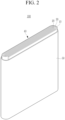
- FIG. 2 is a perspective view of a rechargeable lithium battery according to some embodiments of the present disclosure.
- the rechargeable lithium battery according to one or more embodiments is illustrated as a prismatic battery, but is not limited thereto, and may include variously-shaped batteries such as a cylindrical battery and a pouch battery.
- a rechargeable lithium battery 100 may include an electrode assembly 40 manufactured by winding a separator 30 disposed between a positive electrode 10 and a negative electrode 20 and a case 50 housing the electrode assembly 40.
- An electrolyte may be impregnated in the positive electrode 10, the negative electrode 20 and the separator 30.
- a LiCoO 2 positive active material 0.8 wt% of a polyvinylidene fluoride binder, and 0.85 wt% of a ketjen black conductive material were mixed in an N-methyl pyrrolidone solvent to prepare a positive active material layer slurry.
- the slurry for heat suppression layer was coated on an Al foil current collector and dried to prepare a heat suppression layer and then the positive active material layer slurry was coated on the heat suppression layer, dried, and then pressurized to prepare a positive electrode.
- a thickness of the heat suppression layer was 8.3 ⁇ m and a thickness of the positive active material layer was 41.7 ⁇ m.
- a thickness ratio of the heat suppression layer and the positive active material layer was 1:5.
- an artificial graphite negative electrode Using the positive electrode, an artificial graphite negative electrode, and an electrolyte, a 4500 mAh pouch cell was fabricated.
- the electrolyte was utilized as a 1.35M LiPF 6 dissolved in a mixture of ethylene carbonate, propylene carbonate, ethyl propionate, and propyl propionate (10:15:30:45 by volume ratio).
- a positive electrode was prepared by the same procedure as in Example 1, except that the slurry for heat suppression layer of Example 1 and the positive active material layer slurry of Example 1 were utilized to prepare a heat suppression layer with a thickness of 4.5 ⁇ m and a positive active material layer with a thickness of 45 ⁇ m.
- a thickness ratio of the heat suppression layer and the positive active material layer was 1:10.
- Example 1 Using the positive electrode, and the negative electrode and the electrolyte of Example 1, a 4500 mAh pouch cell was fabricated by the same procedure as in Example 1.
- a positive electrode was prepared by the same procedure as in Example 1, except that the slurry for heat suppression layer of Example 1 and the positive active material layer slurry of Example 1 were utilized to prepare a heat suppression layer with a thickness of 2.4 ⁇ m and a positive active material layer with a thickness of 47.6 ⁇ m.
- a thickness ratio of the heat suppression layer and the positive active material layer was 1:20.
- Example 1 Using the positive electrode, and the negative electrode and the electrolyte of Example 1, a 4500 mAh pouch cell was fabricated by the same procedure as in Example 1.
- a positive electrode was prepared by the same procedure as in Example 1, except that LiFeF 3 with an average particle diameter (D50) of 531 nm was utilized as a heat suppression compound.
- a thickness ratio of the heat suppression layer and the positive active material layer was 1:5.
- Example 1 Using the positive electrode, and the negative electrode and the electrolyte of Example 1, a 4500 mAh pouch cell was fabricated by the same procedure as in Example 1.
- a positive electrode was prepared by the same procedure as in Example 2, except that LiFeF 3 with an average particle diameter (D50) of 531 nm was utilized as a heat suppression compound.
- a thickness ratio of the heat suppression layer and the positive active material layer was 1:10.
- Example 1 Using the positive electrode, and the negative electrode and the electrolyte of Example 1, a 4500 mAh pouch cell was fabricated by the same procedure as in Example 1.
- a positive electrode was prepared by the same procedure as in Example 3, except that LiFeF 3 with an average particle diameter (D50) of 531 nm was utilized as a heat suppression compound.
- a thickness ratio of the heat suppression layer and the positive active material layer was 1:20.
- Example 1 Using the positive electrode, and the negative electrode and the electrolyte of Example 1, a 4500 mAh pouch cell was fabricated by the same procedure as in Example 1.
- a positive electrode was prepared by the same procedure as in Example 1, except that LiFeF 2 with an average particle diameter (D50) of 524 nm was utilized as a heat suppression compound.
- a thickness ratio of the heat suppression layer and the positive active material layer was 1:5.
- Example 1 Using the positive electrode, and the negative electrode and the electrolyte of Example 1, a 4500 mAh pouch cell was fabricated by the same procedure as in Example 1.
- a positive electrode was prepared by the same procedure as in Example 2, except that LiFeF 2 with an average particle diameter (D50) of 524 nm was utilized as a heat suppression compound.
- a thickness ratio of the heat suppression layer and the positive active material layer was 1:10.
- a 4500 mAh pouch cell was fabricated by the same procedure as in Example 1.
- a positive electrode was prepared by the same procedure as in Example 3, except that LiFeF 2 with an average particle diameter (D50) of 524 nm was utilized as a heat suppression compound.
- a thickness ratio of the heat suppression layer and the positive active material layer was 1:20.
- Example 1 Using the positive electrode, and the negative electrode and the electrolyte of Example 1, a 4500 mAh pouch cell was fabricated by the same procedure as in Example 1.
- a positive electrode was prepared by the same procedure as in Example 1, except that TiO 2 with an average particle diameter (D50) of 671 nm was utilized as a heat suppression compound.
- a thickness ratio of the heat suppression layer and the positive active material layer was 1:5.
- Example 1 Using the positive electrode, and the negative electrode and the electrolyte of Example 1, a 4500 mAh pouch cell was fabricated by the same procedure as in Example 1.
- a positive electrode was prepared by the same procedure as in Example 2, except that TiO 2 with an average particle diameter (D50) of 671 nm was utilized as a heat suppression compound.
- a thickness ratio of the heat suppression layer and the positive active material layer was 1:10.
- Example 1 Using the positive electrode, and the negative electrode and the electrolyte of Example 1, a 4500 mAh pouch cell was fabricated by the same procedure as in Example 1.
- a positive electrode was prepared by the same procedure as in Example 3, except that TiO 2 with an average particle diameter (D50) of 671 nm was utilized as a compound for suppressing heat generation.
- a thickness ratio of the heat suppression layer and the positive active material layer was 1:20.
- Example 1 Using the positive electrode, and the negative electrode and the electrolyte of Example 1, a 4500 mAh pouch cell was fabricated by the same procedure as in Example 1.
- a LiCoO 2 positive active material 0.5 wt% of a polyvinylidene fluoride binder, and 0.85 wt% of a ketjen black conductive material were mixed in an N-methyl pyrrolidone solvent to prepare a positive active material layer slurry.
- the positive active material layer slurry was coated on an Al foil current collector, dried, and pressurized to prepare a positive electrode.
- a thickness of the positive active material layer was 50 ⁇ m.
- a positive electrode was prepared by the same procedure as in Example 1, except that the slurry for heat generation suppression layer of Example 1 and the positive active material layer slurry of Example 1 were utilized to prepare a heat suppression layer with a thickness of 10 ⁇ m and a positive active material layer with a thickness of 40 ⁇ m.
- a thickness ratio of the heat suppression layer and the positive active material layer was 1:4.
- Example 1 Using the positive electrode, and the negative electrode and the electrolyte of Example 1, a 4500 mAh pouch cell was fabricated by the same procedure as in Example 1.
- a positive electrode was prepared by the same procedure as in Example 1, except that the slurry for heat generation suppression layer of Example 4 and the positive active material layer slurry of Example 1 were utilized to prepare a heat suppression layer with a thickness of 10 ⁇ m and a positive active material layer with a thickness of 40 ⁇ m.
- a thickness ratio of the heat suppression layer and the positive active material layer was 1:4.
- a positive electrode was prepared by the same procedure as in Example 1, except that the slurry for heat generation suppression layer of Example 4 and the positive active material layer slurry of Example 1 were utilized to prepare a heat suppression layer with a thickness of 2.3 ⁇ m and a positive active material layer with a thickness of 47.7 ⁇ m.
- a thickness ratio of the heat suppression layer and the positive active material layer was 1:21.
- Example 1 Using the positive electrode, and the negative electrode and the electrolyte of Example 1, a 4500 mAh pouch cell was fabricated by the same procedure as in Example 1.
- a positive electrode was prepared by the same procedure as in Example 1, except that the slurry for heat suppression layer of Example 7 and the positive active material layer slurry of Example 1 were utilized to prepare a heat suppression layer with a thickness of 10 ⁇ m and a positive active material layer with a thickness of 40 ⁇ m.
- a thickness ratio of the heat suppression layer and the positive active material layer was 1:4.
- Example 1 Using the positive electrode, and the negative electrode and the electrolyte of Example 1, a 4500 mAh pouch cell was fabricated by the same procedure as in Example 1.
- a positive electrode was prepared by the same procedure as in Example 1, except that the slurry for heat suppression layer of Example 7 and the positive active material layer slurry of Example 1 were utilized to prepare a heat suppression layer with a thickness of 2.3 ⁇ m and a positive active material layer with a thickness of 47.7 ⁇ m.
- a thickness ratio of the heat suppression layer and the positive active material layer was 1:21.
- Example 1 Using the positive electrode, and the negative electrode and the electrolyte of Example 1, a 4500 mAh pouch cell was fabricated by the same procedure as in Example 1.
- a positive electrode was prepared by the same procedure as in Example 1, except that the slurry for heat suppression layer of Example 10 and the positive active material layer slurry of Example 1 were utilized to prepare a heat suppression layer with a thickness of 10 ⁇ m and a positive active material layer with a thickness of 40 ⁇ m.
- a thickness ratio of the heat suppression layer and the positive active material layer was 1:4.
- Example 1 Using the positive electrode, and the negative electrode and the electrolyte of Example 1, a 4500 mAh pouch cell was fabricated by the same procedure as in Example 1.
- a positive electrode was prepared by the same procedure as in Example 1, except that the slurry for heat suppression layer of Example 10 and the positive active material layer slurry of Example 1 were utilized to prepare a heat suppression layer with a thickness of 2.3 ⁇ m and a positive active material layer with a thickness of 47.7 ⁇ m.
- a thickness ratio of the heat suppression layer and the positive active material layer was 1:21.
- Example 1 Using the positive electrode, and the negative electrode and the electrolyte of Example 1, a 4500 mAh pouch cell was fabricated by the same procedure as in Example 1.
- the 4500 mAh pouch cells according to Example 1 to Example 63, and Comparative Examples 1 to 9 were fully charged to 4.47 V cut-off under SOC 100 (charged to be 100% of charge capacity based total charge capacity of cell, if (e.g., when) the cell was charged).
- the fully charged cells were completely pierced through the center utilizing a pin with a diameter of 5 mm at a speed of 50 mm/sec.
- AC alternating current
- Comparative Example 1 without the heat suppression layer had low AC resistance of 41.8 m ⁇ which was able to conduct formation charge and discharge. Thus, it was possible to conduct the full-charge penetration test, but the ignition occurred, indicating deteriorated safety.
- the electronic device, vehicle, and/or the battery e.g ., a battery controller, and/or any other relevant devices or components according to embodiments of the present disclosure described herein may be implemented utilizing any suitable hardware, firmware (e.g ., an application-specific integrated circuit), software, or a combination of software, firmware, and hardware.
- the various components of the device may be formed on one integrated circuit (IC) chip or on separate IC chips.
- the various components of the device may be implemented on a flexible printed circuit film, a tape carrier package (TCP), a printed circuit board (PCB), or formed on one substrate.
- the various components of the device may be a process or thread, running on one or more processors, in one or more computing devices, executing computer program instructions and interacting with other system components for performing the various functionalities described herein.
- the computer program instructions are stored in a memory which may be implemented in a computing device using a standard memory device, such as, for example, a random-access memory (RAM).
- the computer program instructions may also be stored in other non-transitory computer readable media such as, for example, a CD-ROM, flash drive, or the like.
Landscapes
- Chemical & Material Sciences (AREA)
- Chemical Kinetics & Catalysis (AREA)
- Electrochemistry (AREA)
- General Chemical & Material Sciences (AREA)
- Engineering & Computer Science (AREA)
- Manufacturing & Machinery (AREA)
- Composite Materials (AREA)
- Materials Engineering (AREA)
- Inorganic Chemistry (AREA)
- Battery Electrode And Active Subsutance (AREA)
- Secondary Cells (AREA)
- Cell Electrode Carriers And Collectors (AREA)
Applications Claiming Priority (1)
| Application Number | Priority Date | Filing Date | Title |
|---|---|---|---|
| KR1020230092007A KR20250011503A (ko) | 2023-07-14 | 2023-07-14 | 리튬 이차 전지용 양극 및 이를 포함하는 리튬 이차 전지 |
Publications (2)
| Publication Number | Publication Date |
|---|---|
| EP4492486A2 true EP4492486A2 (de) | 2025-01-15 |
| EP4492486A3 EP4492486A3 (de) | 2025-07-16 |
Family
ID=91331306
Family Applications (1)
| Application Number | Title | Priority Date | Filing Date |
|---|---|---|---|
| EP24178902.3A Pending EP4492486A3 (de) | 2023-07-14 | 2024-05-29 | Positivelektrode für eine wiederaufladbare lithiumbatterie und wiederaufladbare lithiumbatterie damit |
Country Status (4)
| Country | Link |
|---|---|
| US (1) | US20250030084A1 (de) |
| EP (1) | EP4492486A3 (de) |
| KR (1) | KR20250011503A (de) |
| CN (1) | CN119314988A (de) |
Family Cites Families (5)
| Publication number | Priority date | Publication date | Assignee | Title |
|---|---|---|---|---|
| JP2010267475A (ja) * | 2009-05-14 | 2010-11-25 | Panasonic Corp | リチウムイオン二次電池 |
| CN103181009B (zh) * | 2010-10-27 | 2016-03-09 | 协立化学产业株式会社 | 导电性底涂剂组合物 |
| TWI431834B (zh) * | 2010-12-27 | 2014-03-21 | Ind Tech Res Inst | 鋰電池與極板結構 |
| CN105637685B (zh) * | 2013-10-07 | 2017-12-12 | 日产自动车株式会社 | 非水电解质二次电池用电极材料、以及使用了其的非水电解质二次电池用电极和非水电解质二次电池 |
| JP7206978B2 (ja) * | 2019-02-06 | 2023-01-18 | トヨタ自動車株式会社 | 全固体電池およびその製造方法 |
-
2023
- 2023-07-14 KR KR1020230092007A patent/KR20250011503A/ko active Pending
- 2023-10-30 US US18/497,942 patent/US20250030084A1/en active Pending
-
2024
- 2024-04-30 CN CN202410538643.5A patent/CN119314988A/zh active Pending
- 2024-05-29 EP EP24178902.3A patent/EP4492486A3/de active Pending
Also Published As
| Publication number | Publication date |
|---|---|
| US20250030084A1 (en) | 2025-01-23 |
| CN119314988A (zh) | 2025-01-14 |
| EP4492486A3 (de) | 2025-07-16 |
| KR20250011503A (ko) | 2025-01-21 |
Similar Documents
| Publication | Publication Date | Title |
|---|---|---|
| EP3734704B1 (de) | Wiederaufladbare lithiumbatterie | |
| EP3734705B1 (de) | Wiederaufladbare lithiumbatterie | |
| EP3961758B1 (de) | Negativelektrode für eine lithiumsekundärbatterie und lithiumsekundärbatterie damit | |
| EP3961759B1 (de) | Anode für lithiumsekundärbatterie und lithiumsekundärbatterie damit | |
| EP3316378B1 (de) | Negative elektrode beinhaltend teilweise ausgerichtetes graphit auf stromsammler für wiederaufladbare lithiumbatterie, sowie wiederaufladbare lithiumbatterie | |
| US10985404B2 (en) | Electrolyte for lithium secondary battery, and lithium secondary battery comprising electrolyte | |
| EP4550473A1 (de) | Wiederaufladbare lithiumbatterien | |
| EP4191779A1 (de) | Separator für eine wiederaufladbare lithiumbatterie und wiederaufladbare lithiumbatterie damit | |
| EP4167332A1 (de) | Elektrodenanordnung und wiederaufladbare lithiumbatterie damit | |
| US20240274802A1 (en) | Negative electrode for rechargeable lithium battery and rechargeable lithium battery including same | |
| EP4492486A2 (de) | Positivelektrode für eine wiederaufladbare lithiumbatterie und wiederaufladbare lithiumbatterie damit | |
| CN119275326A (zh) | 电极组件和包括该电极组件的可再充电的电池 | |
| US10090563B2 (en) | Rechargeable lithium battery and method of preparing same | |
| EP4459700A1 (de) | Wiederaufladbare lithiumbatterie | |
| EP4535450A1 (de) | Negative elektrode für eine wiederaufladbare lithiumbatterie und wiederaufladbare lithiumbatterie damit | |
| EP4485556A1 (de) | Elektrode für eine wiederaufladbare lithiumbatterie und wiederaufladbare lithiumbatterie damit | |
| US20240339659A1 (en) | Additive for rechargeable lithium battery, electrolyte including same and rechargeable lithium battery | |
| EP4468383A1 (de) | Negative elektrode für eine wiederaufladbare lithiumbatterie und wiederaufladbare lithiumbatterie damit | |
| US20240274885A1 (en) | Electrolyte for rechargeable lithium battery and rechargeable lithium battery including the same | |
| EP4492487A1 (de) | Negative elektrode für eine wiederaufladbare lithiumbatterie und wiederaufladbare lithiumbatterie | |
| EP4510219A1 (de) | Negative elektrode für eine wiederaufladbare lithiumbatterie und wiederaufladbare lithiumbatterie damit | |
| US20240429443A1 (en) | Electrolyte for rechargeable lithium battery and rechargeable lithium battery including the same | |
| US20240322240A1 (en) | Rechargeable lithium battery | |
| US20230207817A1 (en) | Negative electrode for rechargeable lithium battery and rechargeable lithium battery including same | |
| US20250006926A1 (en) | Negative active material and rechargeable lithium battery including same |
Legal Events
| Date | Code | Title | Description |
|---|---|---|---|
| PUAI | Public reference made under article 153(3) epc to a published international application that has entered the european phase |
Free format text: ORIGINAL CODE: 0009012 |
|
| STAA | Information on the status of an ep patent application or granted ep patent |
Free format text: STATUS: REQUEST FOR EXAMINATION WAS MADE |
|
| 17P | Request for examination filed |
Effective date: 20240529 |
|
| AK | Designated contracting states |
Kind code of ref document: A2 Designated state(s): AL AT BE BG CH CY CZ DE DK EE ES FI FR GB GR HR HU IE IS IT LI LT LU LV MC ME MK MT NL NO PL PT RO RS SE SI SK SM TR |
|
| REG | Reference to a national code |
Ref country code: DE Ref legal event code: R079 Free format text: PREVIOUS MAIN CLASS: H01M0004131000 Ipc: H01M0004130000 |
|
| PUAL | Search report despatched |
Free format text: ORIGINAL CODE: 0009013 |
|
| AK | Designated contracting states |
Kind code of ref document: A3 Designated state(s): AL AT BE BG CH CY CZ DE DK EE ES FI FR GB GR HR HU IE IS IT LI LT LU LV MC ME MK MT NL NO PL PT RO RS SE SI SK SM TR |
|
| RIC1 | Information provided on ipc code assigned before grant |
Ipc: H01M 4/13 20100101AFI20250609BHEP Ipc: H01M 4/131 20100101ALI20250609BHEP Ipc: H01M 4/136 20100101ALI20250609BHEP Ipc: H01M 4/36 20060101ALI20250609BHEP Ipc: H01M 4/505 20100101ALI20250609BHEP Ipc: H01M 4/525 20100101ALI20250609BHEP Ipc: H01M 4/62 20060101ALI20250609BHEP Ipc: H01M 10/052 20100101ALI20250609BHEP Ipc: H01M 10/42 20060101ALI20250609BHEP |