EP4492028A1 - Sensor element and contact force sensor device - Google Patents
Sensor element and contact force sensor device Download PDFInfo
- Publication number
- EP4492028A1 EP4492028A1 EP23184955.5A EP23184955A EP4492028A1 EP 4492028 A1 EP4492028 A1 EP 4492028A1 EP 23184955 A EP23184955 A EP 23184955A EP 4492028 A1 EP4492028 A1 EP 4492028A1
- Authority
- EP
- European Patent Office
- Prior art keywords
- sensor
- pressure
- cell
- sensor element
- cells
- Prior art date
- Legal status (The legal status is an assumption and is not a legal conclusion. Google has not performed a legal analysis and makes no representation as to the accuracy of the status listed.)
- Pending
Links
Images








Classifications
-
- G—PHYSICS
- G01—MEASURING; TESTING
- G01L—MEASURING FORCE, STRESS, TORQUE, WORK, MECHANICAL POWER, MECHANICAL EFFICIENCY, OR FLUID PRESSURE
- G01L13/00—Devices or apparatus for measuring differences of two or more fluid pressure values
-
- G—PHYSICS
- G01—MEASURING; TESTING
- G01L—MEASURING FORCE, STRESS, TORQUE, WORK, MECHANICAL POWER, MECHANICAL EFFICIENCY, OR FLUID PRESSURE
- G01L5/00—Apparatus for, or methods of, measuring force, work, mechanical power, or torque, specially adapted for specific purposes
- G01L5/0061—Force sensors associated with industrial machines or actuators
- G01L5/0076—Force sensors associated with manufacturing machines
- G01L5/009—Force sensors associated with material gripping devices
-
- G—PHYSICS
- G01—MEASURING; TESTING
- G01L—MEASURING FORCE, STRESS, TORQUE, WORK, MECHANICAL POWER, MECHANICAL EFFICIENCY, OR FLUID PRESSURE
- G01L5/00—Apparatus for, or methods of, measuring force, work, mechanical power, or torque, specially adapted for specific purposes
- G01L5/16—Apparatus for, or methods of, measuring force, work, mechanical power, or torque, specially adapted for specific purposes for measuring several components of force
-
- B—PERFORMING OPERATIONS; TRANSPORTING
- B25—HAND TOOLS; PORTABLE POWER-DRIVEN TOOLS; MANIPULATORS
- B25J—MANIPULATORS; CHAMBERS PROVIDED WITH MANIPULATION DEVICES
- B25J13/00—Controls for manipulators
- B25J13/08—Controls for manipulators by means of sensing devices, e.g. viewing or touching devices
- B25J13/081—Touching devices, e.g. pressure-sensitive
-
- B—PERFORMING OPERATIONS; TRANSPORTING
- B25—HAND TOOLS; PORTABLE POWER-DRIVEN TOOLS; MANIPULATORS
- B25J—MANIPULATORS; CHAMBERS PROVIDED WITH MANIPULATION DEVICES
- B25J13/00—Controls for manipulators
- B25J13/08—Controls for manipulators by means of sensing devices, e.g. viewing or touching devices
- B25J13/081—Touching devices, e.g. pressure-sensitive
- B25J13/084—Tactile sensors
-
- G—PHYSICS
- G01—MEASURING; TESTING
- G01C—MEASURING DISTANCES, LEVELS OR BEARINGS; SURVEYING; NAVIGATION; GYROSCOPIC INSTRUMENTS; PHOTOGRAMMETRY OR VIDEOGRAMMETRY
- G01C5/00—Measuring height; Measuring distances transverse to line of sight; Levelling between separated points; Surveyors' levels
- G01C5/06—Measuring height; Measuring distances transverse to line of sight; Levelling between separated points; Surveyors' levels by using barometric means
-
- G—PHYSICS
- G01—MEASURING; TESTING
- G01K—MEASURING TEMPERATURE; MEASURING QUANTITY OF HEAT; THERMALLY-SENSITIVE ELEMENTS NOT OTHERWISE PROVIDED FOR
- G01K1/00—Details of thermometers not specially adapted for particular types of thermometer
- G01K1/02—Means for indicating or recording specially adapted for thermometers
-
- G—PHYSICS
- G01—MEASURING; TESTING
- G01L—MEASURING FORCE, STRESS, TORQUE, WORK, MECHANICAL POWER, MECHANICAL EFFICIENCY, OR FLUID PRESSURE
- G01L19/00—Details of, or accessories for, apparatus for measuring steady or quasi-steady pressure of a fluent medium insofar as such details or accessories are not special to particular types of pressure gauges
- G01L19/0092—Pressure sensor associated with other sensors, e.g. for measuring acceleration or temperature
-
- G—PHYSICS
- G01—MEASURING; TESTING
- G01L—MEASURING FORCE, STRESS, TORQUE, WORK, MECHANICAL POWER, MECHANICAL EFFICIENCY, OR FLUID PRESSURE
- G01L5/00—Apparatus for, or methods of, measuring force, work, mechanical power, or torque, specially adapted for specific purposes
- G01L5/0061—Force sensors associated with industrial machines or actuators
-
- G—PHYSICS
- G01—MEASURING; TESTING
- G01L—MEASURING FORCE, STRESS, TORQUE, WORK, MECHANICAL POWER, MECHANICAL EFFICIENCY, OR FLUID PRESSURE
- G01L5/00—Apparatus for, or methods of, measuring force, work, mechanical power, or torque, specially adapted for specific purposes
- G01L5/22—Apparatus for, or methods of, measuring force, work, mechanical power, or torque, specially adapted for specific purposes for measuring the force applied to control members, e.g. control members of vehicles, triggers
- G01L5/226—Apparatus for, or methods of, measuring force, work, mechanical power, or torque, specially adapted for specific purposes for measuring the force applied to control members, e.g. control members of vehicles, triggers to manipulators, e.g. the force due to gripping
- G01L5/228—Apparatus for, or methods of, measuring force, work, mechanical power, or torque, specially adapted for specific purposes for measuring the force applied to control members, e.g. control members of vehicles, triggers to manipulators, e.g. the force due to gripping using tactile array force sensors
Definitions
- Embodiments related to a sensor element and a contact force sensor device are described.
- Robots are becoming increasingly intelligent and can perform complex interactions with humans and their environments. These interactions are made possible by the ever more refined processing of stimuli from the robot's environment. These stimuli are perceived by sensors. However, if there is a sense that robots do not easily obtain, it is the sense of touch. To succeed in producing soft surfaces capable of perceiving pressure and their directions, temperature, or even pain are the challenges that the robotic skin or e-skin try to answer.
- Tactile sensing for robotic systems - in particular robotic or prosthetic hands or fingers - is a quite complex topic, since requiring:
- the herein described sensor element and contact force sensor device solves for all three requirements on tactile robotic sensing, and, for example, could be extended by AI based sensor fusion/processing locally and/or centrally. Further, the high dynamic range and low power consumption of the herein described sensor element and contact force sensor device are perfectly matching the needs in target applications
- the inventors realized that one problem encountered when trying to detect a force and/or a pressure stems from the fact that most sensors are direct force sensors not sensible for shear forces.
- this difficulty is overcome by providing a sensor element with mechanically coupled sensor cells.
- the sensor element has an at least partially flexible housing divided into sub-cells by flexible walls. Adjacent sensor cells of the sensor element share a flexible wall/boundary between same. Two adjacent sensor cells may be mechanically coupled via the flexible wall separating the two adjacent sensor cells. This is based on the finding that the mechanical coupling of sensor cells results in high performance multidirectional sensing capabilities. Concurrently, a robust and precise estimation of magnitude and direction of forces acting on the sensor element can be achieved by evaluating a force and/or pressure acting on the individual mechanically coupled sensor cells of the sensor element.
- a sensor element comprises a plurality, e.g., two or more, of mechanically coupled sensor cells, e.g., sub-cells, each having a sealed inner volume, e.g., a cavity, within an at least partially flexible cell housing.
- the flexible cell housing comprises a flexible outer cover and flexible cell boundaries, e.g. walls, between adjacent sensor cells.
- the sensor element comprises at least one pressure sensor element, e.g., one or more pressure sensor elements.
- Each sealed inner volume is fluidically coupled to at least one of the at least one pressure sensor elements.
- the sensor element comprises a pressure sensor element and each sealed inner volume is fluidically coupled to the pressure sensor element.
- the sensor element may comprise a plurality of pressure sensor elements and each sealed inner volume is fluidically coupled to one of the plurality of pressure sensor elements.
- a contact force sensor device comprises a herein described sensor element and a controller configured to read out a momentary pressure information of the one or more of pressure sensor elements of the sensor element and to determine a direction and/or strength, e.g., a vector, of a contact force applied to the sensor element based on the momentary pressure information.
- brackets In the description of the embodiments, terms and text passages placed in brackets (next to a described element or function) are to be understood as further explanations, exemplary configurations, exemplary additions and/or exemplary alternatives of the described element or function.
- the term “lateral” means a direction parallel to the x- and/or y-direction, i.e. parallel to or in the x-y-plane, wherein the term “vertical” means a direction parallel to the z-direction.
- a flexible (elastic) object like a wall, a boundary, a cap or a cover, is deformable and returns to its original position/initial position (initial state) after a deformation.
- Figures 1 to 7c and Fig. 10 describe exemplarily a sensor element 100 with at least two mechanically coupled sensor cells 110 and at least two pressure sensor elements 120.
- the respective sealed inner volume 118 is fluidically coupled to at least one of the at least two pressure sensor elements 120.
- the sensor element 100 comprises as pressure sensor element 120 only one differential pressure sensor element.
- the sensor element 100 may comprise two mechanically coupled sensor cells each one fluidically coupled to the differential pressure sensor element.
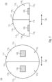
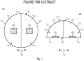
- Fig. 1 and Fig. 2 show exemplarily a sensor element 100, e.g., a cell, with two sensor cells 110 1 and 110 2 , e.g., sub-cells.
- a top view of the respective sensor element 100 is shown on the left and a side view of the respective sensor element 100 is shown on the right.
- the sensor element 100 may have an at least partially flexible housing comprising a flexible cover 114, see the flexible cell cover 114, of the first sensor cell 110 1 and the flexible cell cover 114 2 of the second sensor cell 110 2 and a ground or base 116, see the cell boundaries 116, and 116 2 at the bottom.
- the base 116 of the at least partially flexible housing may be flexible or rigid.
- the flexible cover 114 may also be understood as a flexible outer cover.
- An inner volume of the at least partially flexible housing is divided by a flexible cell boundary 112 into two sealed inner volumes.
- the flexible cell boundary 112 divides the sensor element 100 into the two sensor cells 110 1 and 110 2 .
- the flexible cell boundary 112 is arranged between the two adjacent sensor cells 110 1 and 110 2 , i.e. separating same.
- the flexible cell boundary 112 is shared between the two sensor cells 110 1 and 110 2 .
- the two sensor cells 110 1 and 110 2 are arranged adjacently to each other separated by the common flexible cell boundary 112.
- the first sensor cell 110 1 has a cell housing comprising a flexible outer cover, see the flexible cell cover 114 1 , and the flexible cell boundary 112.
- the second sensor cell 110 2 has a cell housing comprising a flexible outer cover, see the flexible cell cover 114 2 , and the flexible cell boundary 112.
- the sensor element 100 has the shape of a spherical segment or a hemisphere, e.g., a semi-sphere or half-sphere or a spherical dome, and the sensor cells 110 represent subdivisions of the spherical segment (hemisphere), e.g., the spherical segment (hemisphere) may be subdivided into, e.g., equally sized, compartments representing the sensor cells 110.
- the sensor cells 110 may be formed as, e.g., symmetric and/or equally sized, segments (sectors or sections) of a spherical dome.
- the spherical dome for example, comprises a spherical cap, i.e.
- the flexible cover 114 on a circular base area, see the base 116, or on a circular footprint of the sensor element 100.
- the estimation of force directions e.g., by the controller 210 of the contact force sensor device 200 shown in Fig. 3 , is easier, having unidirectional sensitivities for the individual force components.
- the sensor cells 110 of the herein described sensor elements 100 have exemplarily the shape of a spherical segment or the shape of a segment of a hemisphere, but another shape would also be possible, such as cube-shaped, cuboid-shaped, toroid-shaped (ring-shaped), cylinder-shaped or cone-shaped, for example.
- the description is equally applicable to sensor elements 100 having the shape of a cube, cuboid, toroid, a cylinder or a cone, for example.
- Sensor elements 100 having the shape of a spherical segment or being cone-shaped have the advantage that same provide a smaller contact area than flat sensor elements, like cube-shaped, cuboid-shaped, toroid-shaped (ring-shaped) or cylinder-shaped sensor elements 100.
- the contact area e.g., a top area, e.g., an area opposite to the base 116, distributes a contact force to the cells underneath.
- the dome-like shape of a sensor element 100 distributes a force vector on the contacting top area into shape changes and thus different pressure values in the individual sub-cells, i.e. sensor cells. It has been found that it is advantageous, when the top contact area of a sensor element 100 is smaller than the bottom area of the sensor element 100.
- the smaller contact area improves an accuracy at a determination of a direction of the contact force, since a dependency of a deformation of the flexible cover 114 from a shape of an object applying the contact force onto the sensor element 100 is significantly reduced.
- a direction reading i.e. a determined direction of a contact force
- a tilted surface is pressed against a flat cover of the sensor elements, since this may also result in different pressure values in the sensor cells of the sensor element 100, even if the force is only applied vertically from above and has no force component parallel to the base area, see 116.
- flat sensor elements 100 e.g., with a 1D or 2D array of identical single cubic cells or a cylindrical sensor element 100, have shortcomings with regard to shear force measurement, e.g. in addition to contact force measurement.
- Such sensor elements 100 would only measure contact force per cell, which might be sufficient for much simpler applications.
- the sensor cells 110 1 and 110 2 of the sensor element 100 are mechanically coupled.
- Mechanically coupled for example, means that a deformation of one of the two mechanically coupled sensor cells, e.g. of 110 1 or 110 2 , may have an impact on the other sensor cell, like a deformation of the other sensor cell.
- an external force applied to one of the two adjacent sensor cells may deform the flexible cover 114 1 and 114 2 of both sensor cells 110 1 and 110 2 and/or the flexible cell boundary 112 between the two sensor cells 110 1 and 110 2 .
- the cell housings may be impermeable to fluids.
- the sensor cells 110 1 and 110 2 may be filled with a fluid, like a gas, a liquid or a gel.
- Each sensor cell may have a sealed inner volume, see 118 1 and 118 2 , like a cavity, within the at least partially flexible cell housing.
- the fluid may be sealed within each sensor cell 110 1 and 110 2 , e.g., within the respective sealed inner volume, see 118 1 and 118 2 . No fluid crosses the flexible cell boundary112 between the adjacent sensor cells 110 1 and 110 2 , i.e. no fluid is exchanged between the adjacent sensor cells 110 1 and 110 2 .
- the sensor element 100 comprises a plurality of pressure sensor elements 120, e.g. pressure sensor units, i.e. two pressure sensor elements 120 1 and 120 2 .
- the pressure sensor elements 120 1 and 120 2 may be arranged at the bottom 116, see 116, and 116 2 , of the housing of the respective sensor element 100.
- the sensor element 100 comprises two absolute pressure sensor elements 120 1 and 120 2 and in Fig. 2 the sensor element 100 comprises one absolute pressure sensor element 120 1 and one differential pressure sensor element 120 2 .
- the sensor elements 100 shown in Fig. 1 and Fig. 2 are configured for unidirectional shear force sensing. Having two sensor cells, the sensor element 100 may be capable to sense shear forces along one axis 130, e.g., in only one direction.
- the axis 130 may be perpendicular to the cell boundary 112 between the two adjacent sensor cells 110 1 and 110 2 , i.e. perpendicular to a surface of the cell boundary 112 4 in an non-deformed state.
- the sensor elements 100 shown in Fig. 1 and Fig. 2 may be configured to sense lateral forces, e.g., shear forces at a sensor interface, i.e. at a top of the flexible cover 114.
- the sensor element 100 is sensitive for vertical forces, i.e. forces perpendicular to the cover 114.
- This sensor elements 100 can be fixed to a mechanical grip element to detect efficiently and with high accuracy whether an object is properly griped or whether the object slips, i.e. as a stick-slip sensor on mechanical grip elements.
- the two-cell sensor element 100 might be advantageous in situations where only one-directional shear force is relevant, i.e. gripping and lifting of objects, since shear force would only appear in lateral direction. The two-cell sensor would then be sufficient, but be much simpler and cheaper to manufacture, realize and operate than a sensor element with three or more sensor cells, as shown in Fig. 4 to 10 .
- Fig. 1 shows an embodiment, where the plurality of pressure sensor elements 120 represent absolute pressure sensors.
- the sensor element 100 for example, comprises only absolute pressure sensors and each sensor cell 110 comprises one of the absolute pressure sensors, i.e. each sealed inner volume 118 is fluidically coupled to one of the plurality of pressure sensor elements.
- the first sealed inner volume 118 1 of the first sensor cell 110 1 is fluidically coupled to a first absolute pressure sensor element 120 1 and the second sealed inner volume 118 2 of the second sensor cell 110 2 is fluidically coupled to a second absolute pressure sensor element 120 2 .
- the plurality of pressure sensor elements 120 may comprise a plurality of absolute pressure sensor elements and each sensor cell 110 of a sensor element 100 may comprise one of the absolute pressure sensor elements 120 fluidically coupled to the sealed inner volume 118 of the respective sensor cell 110.
- the sensor element 100 may be configured to detect an external force applied to the sensor element 100, e.g., a force applied to the flexible cover 114, i.e. to the flexible cell cover 114, of the first sensor cell 110, and/or to the flexible cell cover 114 2 of the second sensor cell 110 2 , by detecting for each sensor cell 110 1 and 110 2 an absolute pressure within the fluid in the sealed inner volume 118 1 /118 2 of the respective sensor cell 110 1 /110 2 by the respective pressure sensor element 120 1 /120 2 .
- a respective absolute pressure sensor element 120 1 /120 2 may be coupled to the respective sealed inner volume 118 1 /118 2 in order to evaluate the pressure of both cells individually.
- the sensor element 100 is configured to obtain a momentary pressure information comprising a first absolute pressure value obtained from the first absolute pressure sensor element 120 1 and a second absolute pressure value obtained from the second absolute pressure sensor element 120 2 .
- a pressure difference between the two adjacent sensor cells, see the first sensor cell 110 1 and the second sensor cell 110 2 is determinable, e.g. by the controller 210 in Fig. 3 , based on the absolute pressure values obtained from the absolute pressure sensors of the two adjacent sensor cells.
- the absolute pressure values and the pressure difference may be an indication for a magnitude and direction of an external force applied to the sensor element 100.
- the sensor element 100 may comprises a combination of at least one absolute pressure sensor and at least one differential pressure sensor.
- the plurality of pressure sensor elements 120 comprises one or more absolute pressure sensors and one or more differential pressure sensors.
- Fig. 2 shows an embodiment, with one absolute pressure sensor element 120 1 and one differential pressure sensor element 120 2 .
- the first sealed inner volume 118 1 of the first sensor cell 110 1 is fluidically coupled to the absolute pressure sensor element 120 1 and to the differential pressure sensor element 120 2 and the second sealed inner volume 118 2 of the second sensor cell 110 2 is fluidically coupled to the differential pressure sensor 120 2 .
- the differential pressure sensor element 120 2 is fluidically coupled to the sealed inner volume 118 1 of the first sensor cell 110 1 and to the sealed inner volume 118 2 of the second sensor cell 110 2 .
- each sealed inner volume see 118 1 and 118 2 , is fluidically coupled to the differential pressure sensor element 120 2 .
- a differential pressure sensor element 120 2 may be fluidically coupled to the sealed inner volumes 118 1 and 118 2 of two adjacent sensor cells 110 of a sensor element 100 for evaluating a pressure difference.
- the differential pressure sensor element 120 2 crosses the flexible cell boundary 112 between the adjacent sensor cells 110 1 and 110 2 .
- Adjacent sensor cells 110 1 and 110 2 are sensor cells sharing a cell boundary 112 or being separated by a cell boundary 112.
- the differential pressure sensor element 120 2 may be fluidically coupled to the two sealed inner volumes 118 1 and 118 2 being separated by the cell boundary 112.
- a herein described sensor element 100 may comprise two adjacent sensor cells, e.g., 110 1 and 110 2 in Fig. 2 , 7b or 7c , wherein at least one of the two adjacent sensor cells 110 1 and 110 2 comprises an absolute pressure sensor, see 120 1 in Fig. 2 and 120 2 in Fig. 7b and 7c , of the at least one absolute pressure sensors.
- a sealed inner volume, see 118 1 , of a first sensor cell, see 110 1 is fluidically coupled to the absolute pressure sensor.
- sealed inner volumes, see 118 1 and 118 2 , of the two adjacent sensor cells 110 1 and 110 2 are fluidically coupled to the same differential pressure sensor 120 2 of the at least one differential pressure sensors, i.e. to a common differential pressure sensor.
- the differential pressure sensor is fluidically coupled to the sealed inner volume 118 1 of the first sensor cell 110 of the two adjacent sensor cells 110 and to the sealed inner volume 118 2 of a second sensor cell 110 of the two adjacent sensor cells 110.
- a number of the sensor cells 110 may be two, e.g., the sensor element 100 comprises the two adjacent sensor cells 110 1 and 110 2 , as shown in Fig. 2 .
- the sensor element 100 may comprise additionally to the two adjacent sensor cells 110 1 and 110 2 further mechanically coupled sensor cells 100 fluidically coupled to at least one of the plurality of pressure sensor elements 120, as shown in Fig. 7b and 7c .
- the sensor element 100 shown in Fig. 2 may be configured to detect an external force applied to the sensor element 100, e.g., a force applied to the flexible cover 114, i.e. to the flexible cell cover 114 1 of the first sensor cell 110, and/or to the flexible cell cover 114 2 of the second sensor cell 110 2 , by detecting an absolute pressure within the fluid sealed within the first sensor cell using the absolute pressure sensor element 120 1 and by detecting a pressure difference between fluids sealed within the two adjacent sensor cells, i.e. between the first sensor cell 110 1 and the second sensor cell 110 2 , using the differential pressure sensor element 120 2 .
- An absolute pressure within the second sensor cell 110 2 is determinable, e.g. by the controller 210 in Fig.
- a combination of the absolute pressure value and the pressure difference may be an indication for a magnitude and/or a direction of an external force applied to the sensor element 100.
- the second sensor cell 110 2 may also comprise an absolute pressure sensor.
- the sensor element 100 comprises redundant pressure sensor elements.
- Such an embodiment may be especially advantageous in sensible environments, since a high accuracy and/or high robustness is achieved.
- the embodiments of the sensor element 100 shown in Fig. 1 and Fig. 2 have the advantage that same enable a determination of a direction and a magnitude of a force applied to the respective sensor element 100. With the sensor elements 100 shown in Fig. 1 and Fig. 2 it is possible to detect vertical and horizontal forces.
- a contact force sensor device 200 may comprise one or more of the herein described sensor elements 100 in order to determine or evaluate a contact force 202 applied to the one or more sensor elements 100, i.e., to measure vertical and/or shear force at a contact point.
- the read out of the at least two pressure sensor elements 120 of the sensor element 100 or of the pressure sensor elements 120 of two or more sensor elements 100 and the determination of the contact force 202, e.g., a direction and a strength of the contract force 202, like a vector, may be performed by a controller 210 comprised by the contact force sensor device 200.
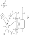
- Fig. 3 shows schematically a contact force sensor device 200 comprising exemplarily the sensor element 100 of Fig. 1 and a controller 210.
- the contact force sensor device 200 may alternatively comprise any other herein described sensor element 100 or combination of sensor elements 100.
- the controller 210 is configured to read out the plurality of pressure sensor elements, i.e. the first pressure sensor element 120 1 and the second pressure sensor element 120 2 , of the sensor element 100 to obtain a momentary pressure information 204.
- the momentary pressure information 204 comprises one or more pressure values read from the plurality of pressure sensor elements 120.
- the controller 210 is configured to obtain a first pressure value 122 1 associated with the first sensor cell 110 1 , e.g., by reading out the first pressure sensor element 120 1 , and/or a second pressure value 122 2 associated with the second sensor cell 110 2 , e.g., by reading out the second pressure sensor element 120 2 .
- the momentary pressure information 204 comprises, e.g., represents, two pressure value, i.e. an absolute pressure read from the absolute pressure sensor 120 1 and a pressure difference read from the differential pressure sensor 120 2 .
- the momentary pressure information 204 may comprise for each of the at least two pressure sensor elements 120 of a herein described sensor element 100 a pressure value.
- the momentary pressure information 204 may comprise a vector of two or more pressure values, each of which is associated with one of the two or more pressure sensor elements 120. If no pressure, e.g. no absolute pressure or no pressure difference, is detected by a pressure sensor element 120 of the plurality, e.g., two or more, of pressure sensor elements 120, the respective read out pressure value 122 may be zero. It may also be possible, that the momentary pressure information 204 comprises only pressure values unequal to zero together with an indication of the pressure sensor element 120 from which the respective pressure value is read out.
- the sensor element 100 may comprise within its base wall 116, e.g. a wall opposite to the cover 114 of the sensor element 100, an electronic circuit and/or an interface for providing one or more pressure values detected by the at least one pressure sensor element 120.
- the at least one pressure sensor element 120 is arranged on, e.g., fixed to, an inner surface of the base wall 116, i.e. a surface facing the sealed inner volume, see 118 1 and 118 2 .
- the controller 210 is embedded or integrated within the base wall 116 and connected to each pressure sensor element 120 of the sensor element 100 via the electronic circuit.
- the sensor element 100 comprises a mounting base.
- the sensor cells 110 for example, are arranged, e.g., fixed, in or on the mounting base 140, e.g., see Fig. 6 , Fig. 8 , Fig. 9 and Fig. 11 .
- the mounting base 140 for example, comprises the electronic circuit and/or the interface.
- the controller 210 is embedded or integrated within the mounting base 140 and, for example, connected to each pressure sensor element 120 of the sensor element 100 via the electronic circuit.
- the interface may be configured to transmit the momentary pressure information 204 on a transmission medium such as a wireless transmission medium or a wired transmission medium to the controller 210.
- a transmission medium such as a wireless transmission medium or a wired transmission medium to the controller 210.
- the transmission medium for example, is a wired or wireless connection based on, e.g., I2C, SPI, Bluetooth, BLE, etc.
- the controller 210 can be located local to, e.g., in the vicinity of, the one or more sensor elements 100. Additionally, or alternatively, it may be possible that the controller 210 comprises two or more processing units at distributed hierarchy levels, e.g. a combination of one or more local processing units, e.g., per sensor element 100 or for a set of locally grouped/clustered sensor elements 100 (e.g., at a finger tip area), and an upper layer processing unit configured to obtain signals from the one or more local processing units.
- the controller 210 may comprise two or more upper layer processing units, each one configured to obtain signals from a different set of one or more local processing units, and an overall processing unit configured to obtain signals from the two or more upper layer processing units.
- An upper layer processing unit may be configured to obtain one or more signals from the associated local processing units to combine / process and/or distribute the one or more signals to the overall processing unit.
- the controller 210 is configured to determine information 212 regarding a direction and/or a strength, e.g., a vector, of the contact force 202 applied to the sensor element 100 based on the momentary pressure information 204.
- a vertical component 202 z of the contact force 202 may be determined based on a sum of the absolute pressure value, see 122 1 , read out from the absolute pressure sensor element comprised by the first sensor cell 110 1 , see 120 1 , and the absolute pressure value, see 122 2 , read out from the absolute pressure sensor element comprised by the second sensor cell 110 2 , see 120 2 .
- a horizontal component 202 x of the contact force 202 may be determined based on a difference between the absolute pressure value, see 122 1 , read out from the absolute pressure sensor element comprised by the first sensor cell 110 1 , see 120 1 , and the absolute pressure value, see 122 2 , read out from the absolute pressure sensor element comprised by the second sensor cell 110 2 , see 120 2 .
- the determined information 212 may comprise the vertical component 202 z and the horizontal component 202 x , e.g., as a vector.
- the controller 210 may be configured to determine the horizontal component 202 x of the contact force 220 based on the pressure difference p diff read from the differential pressure sensor, see 120 2 .
- the vertical component F z 202 z can be determined based on the absolute pressure value p abs read from the absolute pressure sensor, see 120 1 , and the pressure difference p diff read from the differential pressure sensor, see 120 2 , e.g. F z ⁇ (2 ⁇ p abs + p diff ).
- the determined information 212 may comprise the vertical component 202 z and the horizontal component 202 x , e.g., as a vector.
- the controller 210 may be configured to combine pressure values comprised by the momentary pressure information 204 to determine the vertical component 202 z and/or the horizontal component 202 x of the contact force 202, i.e. combine momentary pressure values read out of two or more pressure sensor elements 120 to determine the direction and/or strength of the contact force 202.
- the outer cover 114 1 of the first sensor sensor cell 110 1 and the outer cover 114 2 of the second sensor cell 110 2 of the sensor element 100 are flexible, i.e. deformable by an external force, e.g. the contract force 202.
- a deformation of a sensor cell 110, see 110 1 and 110 2 may result in a change of a pressure within the respective sensor cell 110, e.g. compared to a reference pressure associated with a non-deformed sensor cell 110, i.e. a pressure within the sealed inner volume 118, see 118 1 and 118 2 , of the respective sensor cell 110 when same is not deformed.
- a deformation of a sensor cell, see 110 2 , onto which the contact force 202 is applied may also result in a deformation of sensor cells, see 110 1 , neighboring the sensor cell 110 2 onto which the contact force 202 is applied.
- the sensor cell 110 2 onto which the contact force 202 is applied and the neighboring mechanically coupled sensor cell, see 110 1 are deformed by the contact force 202.
- the mechanical coupling of the sensor cells 110 allows a two-dimensional evaluation of the contact force 202 by a sensor element 100 with a one-dimensional arrangement of its sensor cells 110, e.g., compare Fig. 1 and 2 , and a three-dimensional evaluation of the contact force 202 by a sensor element 100 with a two-dimensional arrangement of its sensor cells 110, e.g., compare Fig. 4-10 .
- Fig. 1 to 3 show exemplarily a sensor element 100 with two sensor cells 110 1 and 110 2 .
- same could be implemented with three or more sensor cells, e.g., as shown in Fig. 4 to 10 .
- a sensor element 100 comprises n sensor cells 110, wherein n is an integer equal to or greater than 2, 3, 5 or 10.
- Fig. 3 shows exemplarily a contact force sensor device 200 with one sensor element 100.
- the contact force sensor device 200 comprises two or more sensor elements 100, e.g. arranged in a one-dimensional array, see Fig. 4 , or arranged in a two-dimensional array, see Fig. 5 .
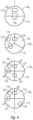
- Fig. 4 shows an embodiment of a one-dimensional array of sensor elements, see 100 1 to 100 4 , i.e. the sensor elements 100 are arranged in form of a one-dimensional array.
- Fig. 4 shows exemplarily, a one-dimensional array of different sensor elements 100.
- a one-dimensional array of identical sensor elements 100 i.e. of sensor elements of the same type, is also possible.
- the sensor elements 100 of the one-dimensional array can differ among each other in a number of sensor cells comprised by each sensor element and/or in a number and/or arrangement of pressure sensor elements 120 of each sensor element 100.
- Fig. 5 shows an embodiment of a two-dimensional array of sensor elements, see 100, to 100 4 , i.e. the sensor elements 100 are arranged in form of a two-dimensional array.
- Fig. 5 shows exemplarily a two-dimensional array of identical sensor elements 100, i.e. of sensor elements 100 of the same type.
- the two-dimensional array can comprise sensor elements differing among each other, e.g., in a number of sensor cells and/or in a number and/or arrangement of pressure sensor elements 120.
- the sensor elements 100 comprise four sensor cells 110, alternatively, it is possible that another number of sensor cells 110 can be comprised by the sensor elements 100.
- the two-dimensional arrangement can comprise nxn sensor elements 100 or nxm sensor elements 100, wherein n is an integer equal to or greater than 2, 3, 5 or 10 and wherein m is an integer equal to or greater than 2, 3, 5 or 10.
- nxm sensor elements 100 the integer n is unequal to the integer m.
- a one-dimensional array of sensor elements 100 comprises two or more sensor elements 100 of a first type of sensor elements and two or more sensor elements of a second type of sensor elements.
- the first type of sensor elements 100 may differ from the second type of sensor elements 100 in a number of sensor cells and/or in a number and/or arrangement of pressure sensor elements 120.
- a type of a sensor element 100 may define a number of sensor cells 110 of the sensor element 100 and/or a number and/or arrangement of pressure sensor elements 120 of the sensor element 100.
- Fig. 4 shows exemplarily sensor elements 100 with different pressure sensor element numbers and arrangements.
- Fig. 5 shows exemplarily sensor elements 100 with the same number and arrangement of pressure sensor elements 120.
- Different configurations are possible for each sensor element 100 of the one-dimensional or two-dimensional arrangement of sensor elements, like only absolute pressure sensors or a combination of absolute pressure sensors and differential pressure sensors.
- the arrangement of a plurality of sensor elements 100 e.g., as shown in Fig. 4 and 5 , in a one-dimensional or two-dimensional arrangement enables a monitoring of a large area. With such arrangements it may be possible to detect and evaluate with a herein discussed contact force sensor device 200 a plurality of forces applied to the array of sensor elements 100.
- the two-dimensional arrangement of Fig. 5 may be designed/formed as a mat of a plurality of sensor elements 100.
- the three may be configured to, based on pressure values received from a plurality of pressure sensor elements 120 of the mat of plurality of sensor elements 100, determine a two-dimensional force field, e.g., a vector field, showing at least one force applied to the mat, i.e. to the sensor element 100 arranged on the mat.
- the two-dimensional force field may indicate a location and a magnitude and/or a direction of at least one force within a two-dimensional area, i.e. within the two-dimensional area spanned by the sensor elements 100.
- the one-dimensional or two-dimensional arrangement of sensor elements 100 may be configured to detect and evaluate a plurality of forces applied to one or more of the sensor elements 100 of the one-dimensional or two-dimensional arrangement. It might be advantageous, if the one-dimensional arrangement of sensor elements 100 comprises at least 5, 10, 20 or 30 sensor elements 110 in a row, as described with regard to Fig. 4 , or if the two-dimensional arrangement of sensor elements 100 comprises nxn or nxm sensor elements 100 with n being an integer equal to or greater than 5, 10, 20 or 30 and with m being an integer equal to or greater than 5, 10, 20 or 30, as described with regard to Fig. 5 . In this case, for example, pressure values associated with different parts of the arrangement may be considered by the controller 210 of Fig.
- the controller 210 may be configured to identify within an area of the one-dimensional or two-dimensional arrangement of sensor elements 100 a sensor element 110 providing the highest pressure value, e.g., highest absolute pressure or highest pressure difference, and base the determination of the magnitude and/or direction of the force on pressure values associated with sensor elements 100 surrounding the identified sensor element 100, i.e. the sensor elements 100 associated with the highest pressure value, e.g., pressure values associated with the next and the next-but-one sensor element with respect to the identified sensor element may be taken into account.
- Pressure values associated with sensor elements 100 located within a further area of the one-dimensional or two-dimensional arrangement of sensor elements 100 may be considered similarly to determine a further force applied in the further area.
- the controller 210 of the contact force sensor device 200 shown in Fig. 3 may analyze a contact force 202 applied to one or more of the sensor elements 100 shown in Fig. 4 or 5 by evaluating pressure values of each sensor element 100 individually, as described with regard to Fig. 3 , or by combining pressure values of two or more sensor elements 100.
- the plurality of sensor elements 100 may be connected to the controller 210.
- the plurality of sensor elements 100 may be configured to cover a mat or an area of a device, like a finger area of a robot in a one-dimensional or two-dimensional arrangement.
- the plurality of sensor elements 100 may be arranged on, e.g., fixed to, a common mounting base.
- the controller 210 may be configured to read out pressure values of each of the plurality of sensor elements 100, for example, each sensor element 100 may be configured to provide a momentary pressure information comprising one or more pressure values associated with the one or more pressure sensor elements 120 of the respective sensor element 100.
- controller 210 may be configured to determine a direction and/or a strength and/or a position of a force contact point on the one-dimensional or two-dimensional arrangement of sensor elements of one or more contact forces applied to the plurality of sensor elements 100 based on the momentary pressure information.
- the contact force sensor device 200 comprises a flexible cover layer arranged on the plurality of sensor elements 100, e.g., on top of the array, i.e. on the one-dimensional arrangement or the two-dimensional arrangement of sensor elements 100, e.g., covering the plurality of sensor elements 100.
- the flexible cover layer may be configured to mechanically couple the plurality of sensor elements 100.
- a force applied to the flexible cover layer may be distributed over several sensor elements 100 of the plurality of sensor elements 100. This increases a resolution for location, but reduces measuring the contact area (locality) over the array. This might be useful for specific use-cases, e.g. touch panels.
- the flexible cell covers 114 of the sensor cells 110 of a sensor element 100 may be configured to distributed an applied force over several sensor cells 110 of the respective sensor element 100. This increases an accuracy and/or robustness at a force determination using the respective sensor element 100.
- Figures 1 to 5 already show that a herein described sensor element 100 can be realized with different numbers of sensor cells 110 and with different arrangements of the two or more pressure sensors 120.
- Figures 6 to 7c implementation options with regard to the numbers of sensor cells 110 and with regard to possible different arrangements of the two or more pressure sensors 120 are described in more detail.
- the features and/or functionalities described with regard to the sensor elements 100 in Fig. 1 to 5 are also applicable to the sensor elements 100 in Fig. 6 to 7c and also the other way around. This applies especially with regard to the at least two pressure sensor elements 120 within the sensor element 100, with regard to the base 116, i.e.
- a bottom sensor wall with regard to a mounting base 140 and with regard to an implementation of the respective sensor element 100 within the contact force sensor device 200 in Fig. 3 , i.e. with regard to a read out of the pressure values and a determination of the contact force 202.
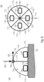
- Fig. 6 shows exemplarily the sensor element 100 in form of a spherical segment or a hemisphere once in a side view on the left and once in a top view on the right.
- the sensor element 100 comprises exemplarily four mechanically coupled sensor cells 110 1-4 , e.g., just like the sensor elements 100 shown in Fig. 5 or as the sensor elements 100 3 and 100 4 in Fig. 4 .
- another number of sensor cells 110 could be implemented.
- the spherical segment (hemisphere) could be subdivide into two halves, i.e. a sensor element 100 with two sensor cells 110 like the one shown in Fig. 1 and Fig. 3 .
- Embodiments of the sensor element 100 in form of a spherical segment or hemisphere with three sensor cells can be seen in Fig. 7a to Fig. 7c and in Fig. 4 (see 100 2 in Fig. 4 ).
- the sensor element 100 in form of a spherical segment or a hemisphere may comprise n sensor cells 110, wherein n is an integer equal to or greater than 2.
- An upper limit for the number of sensor cells 110 may depend on an area of a circle spanned by the spherical segment or the hemisphere, i.e. on a size of a base area 116 of the sensor element 100.
- the upper limit of sensor cells 110 may be 3, 4 or 6.
- Each sensor cell 110 has a sealed inner volume 118, see 118 1-4 , within an at least partially flexible cell housing.
- the sensor cells 110 for example, are filled with either gas or liquid, easily done in a way to show the same initial pressure for unloaded conditions.
- the flexible cell housing i.e. a sensor cell housing, comprises a flexible outer cover 114, see 114 1-4 , and flexible cell boundaries 112 between adjacent sensor cells 110.
- a sensor cell 110 within a spherical segment or a hemisphere, for example, has one flexible outer cover 114 and two flexible cell boundaries 112 between the respective sensor cell 110 and two adjacent sensor cells 110. This is, for example, the case for sensor elements 100 with three or more sensor cells 110.
- the flexible cell boundaries 112 subdivide the spherical segment (hemisphere) into the sensor cells 110.
- the flexible outer covers 114 1-4 of all sensor cell housings form together an overall outer cover in form of a spherical segment or a hemisphere of the sensor element 100.
- a sensor cell i.e. the sensor element 100
- a set of sub-cells i.e. sensor cells 110
- each encapsulated by a flexible cell housing i.e., flexible cell walls
- all sub-cells are mechanically coupled as a single sensor structure.
- Fig. 6 shows such a multi-cell sensor unit, i.e. the sensor element 100.
- the typical cross section is shown on the left in Fig. 6 , exemplarily for a 4-cell structure, which is, e.g., mounted on a given base surface, i.e. a mounting base 140.
- the sensor element 100 may comprise a mounting base 140 onto which the sensor cells 110 are arranged, e.g., mounted or fixed.
- the mounting base 140 may comprise an electronic circuit and/or an interface connected to the plurality of pressure sensor elements 120.
- the mounting base 140 e.g., is a flexible mounting base, e.g., comprising flex-pcb-material, silicon-material or rubber-material, or a rigid mounting base, e.g., comprising rigid-pcb-material.
- the sensor element 100 comprises a plurality of pressure sensor elements 120, which are exemplarily absolute pressure sensors, e.g., as described with regard to the sensor element 100 in Fig. 1 , 3 and 5 .
- Each sensor cell 110 comprises one of the absolute pressure sensors, i.e. each sensor cell is fluidically coupled to one of the absolute pressure sensors.
- the plurality of pressure sensor elements 120 might comprise one or more differential pressure sensors. This results in redundant pressure sensor elements improving an accuracy and robustness of the sensor element 100.
- a differential pressure sensor can be coupled between two adjacent sensor cells, e.g. crossing a cell boundary 112 and being fluidly coupled to the inner volume 118 of the respective two adjacent sensor cells 110, i.e.
- the plurality of pressure sensor elements 120 comprise at least one absolute pressure sensor and at least one differential pressure sensor, e.g., see Fig. 2 , Fig. 4 , Fig. 7b and Fig. 7c .
- one absolute pressure sensor and three differential pressure sensors see 100 3 in Fig. 4 , may be sufficient for a fourcell sensor element 100.
- one of the sensor cells 110 may comprise an absolute pressure sensor and three of the four cell boundaries 112 may be crossed by a respective differential pressure sensor.
- Each sensor cell 110 for example, may be equipped with a pressure sensor, e.g., an absolute pressure sensor and/or a differential pressure between two mechanically coupled sensor cells 110.
- Absolute pressure sensors are not shared among sensor cells 110, i.e. only one sensor cell 110 is fluidically coupled to one absolute pressure sensor.
- the number of absolute pressure sensors 120 may corresponds to the number of sensor cells 110 of the sensor element 100, as shown in Fig. 1 , Fig. 5 and Fig. 6 .
- the controller 210 of one of the herein described contact force sensor devices 200 may analyze a contact force 202 applied to such a sensor element 100 by calculating a sum of all obtained pressure values to determine a magnitude of a contact force and by calculating pressure differences using pressure values obtained from adjacent sensor cells 110 to determine a direction of the contact force.
- the controller 210 may be configured to combine two or more absolute pressure values obtained from the plurality of differential pressure sensors 120 to determine a direction and/or a magnitude of the contact force.
- a vertical component of a force applied to the sensor element 100 is determinable based on a sum of absolute pressure values and/or a direction of the force applied to the sensor element 100 is determinable based on differences between absolute pressure values of neighboring sensor cells 110.
- the two-cell arrangement in Fig. 2 allows only a uni-directional force determination.
- a sensor element 100 with three or more sensor cells 110 allows a three-dimensional force direction determination.
- Fig. 6 shows a vertical tactile force F z 202 z acting on an upper part of the flexible sensor structure, i.e. an upper part of the sensor housing of the sensor element 100.
- the cell boundaries 112 and the cover 114 may be made out of flexible material.
- the potentially non-linear function f z is used to calculate the force 202 from the sensor readings, the cell temperature T, e.g., also available from each pressure sensor, and the outside atmospheric pressure p 0 , which can be easily measured by an optional reference sensor outside the sensor structure, e.g., compare also Fig. 10 for the determination of the cell temperature and the outside atmospheric pressure p 0 .
- the sensor readings may represent the momentary pressure information 204 comprising a first pressure value p 1 associated with the pressure sensor element 120 1 , a second pressure value p 2 associated with the pressure sensor element 120 2 , a third pressure value p 3 associated with the pressure sensor element 120 3 , and a fourth pressure value p 4 associated with the pressure sensor element 120 4 .
- F y f y p 2 ⁇ p 4 , T ... shear force in y-direction
- the functions f x and f y may also be potentially non-linear functions, e.g., describing a potentially non-linear relationships between pressure and temperature readings from the applied forces F x , F y .
- the sensor element 100 is capable to measure or evaluate
- Fig. 6 shows exemplarily a four sensor cell 110 geometry.
- An alternative sub-cell geometries are also possible, e.g. a 3-cell geometry as depicted in Fig. 7a to 7c .
- Fig. 7a to Fig. 7c show different arrangements of the plurality of pressure sensor elements 120, see 120 1 to 120 6 , for a sensor element 100 with three sensor cells 110, see 110 1 to 110 3 .
- the arrangements of the plurality of pressure sensor elements 120 shown in Fig. 7a to Fig. 7c can be adapted for any other number n of sensor cells, wherein n is an integer equal to or greater than 2, e.g., for the sensor element 100 of Fig. 6 with four sensor cells 110.
- Fig. 7a shows an embodiment of a sensor element 100 with absolute pressure sensors 120 1 to 120 3 as the plurality of pressure sensor elements.
- the respective sealed inner volume, 118 1 to 118 3 is fluidically coupled to one of the absolute pressure sensors 120 1 to 120 3 .
- Each sensor cell 110 1 to 110 3 comprises a different one of the plurality of pressure sensor elements.
- the plurality of pressure sensor elements comprises one absolute pressure sensor 120 per sensor cell 110.
- the arrangement shown in Fig. 7a can also be adapted for n sensor cells 110, wherein n is an integer equal to or greater than two.
- Each sensor cell 110 comprises one of n absolute pressure sensors, i.e. there is one absolute pressure sensor for each sensor cell 110.
- Fig. 7b shows an embodiment of a sensor element 100 with one absolute pressure sensor 120 2 and two differential pressure sensors 120 1 and 120 3 as the plurality of pressure sensor elements.
- One sensor cell e.g., a first sensor cell 110 1
- the absolute pressure sensor i.e. the sealed inner volume 118 1 of the first sensor cell 110
- the sealed inner volume 118 1 of the first sensor cell 110 1 is fluidically coupled to the two differential pressure sensors 120 1 and 120 3 , i.e. to a first differential pressure sensor 120 1 and to a second differential pressure sensor 120 3
- the first differential pressure sensor 120 1 is further coupled to the sealed inner volume 118 3 of a third sensor cell 110 3 , i.e.
- the second differential pressure sensor 120 3 is further coupled to the sealed inner volume 118 2 of a second sensor cell 110 2 , i.e. a second adjacent sensor cell.
- the first sensor cell 110 1 is arranged adjacent to the second sensor cell 110 2 and to the third sensor cell 110 3 and the second sensor cell 110 2 is arranged adjacent to the third sensor cell 110 3 .
- the first sensor cell 110 1 and the second sensor cell 110 2 represent two adjacent sensor cells
- the first sensor cell 110 1 and the third sensor cell 110 3 represent two adjacent sensor cells
- the second sensor cell 110 2 and the third sensor cell 110 3 represent two adjacent sensor cells.
- the arrangement shown in Fig. 7b can be adapted for any other number of sensor cells 110, e.g., for n sensor cells, wherein n is an integer equal to or greater than two.
- the plurality of pressure sensor elements comprise one absolute pressure sensor and n-1 differential pressure sensors.
- One of the n sensor cells 110 comprises the absolute pressure sensor and the n-1 differential pressure sensors are arranged at cell borders, each differential pressure sensor coupling to two adjacent sealed inner volumes separated from each other by the cell border at which the respective pressure sensor is arranged. Only one cell border is not crossed by a differential pressure sensor.
- the plurality of pressure sensor elements 120 may be arranged, so that no redundant pressure sensor elements 120 are present within the sensor element 100, but so that vertical forces as well as horizontal forces are determinable. This is, for example, the case for the embodiments described with regard to Fig. 7a and Fig. 7b . This can also be realized with a different arrangement. For example, considering the sensor element 100 shown in Fig.
- the first differential pressure sensor 120 1 can be replace by an absolute pressure sensor comprised by the third sensor cell 110 3 or the second differential pressure sensor 120 3 can be replace by an absolute pressure sensor comprised by the second sensor cell 110 2 or both differential pressure sensors 120 1 and 120 3 can be replace by an absolute pressure sensor comprised by the second sensor cell 110 2 or the third sensor cell 110 3 and by a differential pressure sensor coupled to the sealed inner volume 118 2 of the second sensor cell 110 2 and to the sealed inner volume 118 3 the third sensor cell 110 3 .
- different embodiments for sensor elements 100 with another number of sensor cells than three are also possible. For example, no differential pressure sensor needs to be arranged between two adjacent sensor cells, which both comprise an absolute pressure sensor.
- a differential pressure sensor may only be coupled between sealed inner volumes of two predefined adjacent sensor cells, wherein no more than one of the two predefined adjacent sensor cells may comprise an absolute pressure sensor, see also 100 4 in Fig. 4 .
- the plurality of pressure sensor elements 120 for example, comprises at least one differential pressure sensor, the plurality of pressure sensor elements 120 has to further comprise at least one absolute pressure sensor for being able to determine vertical forces as well as horizontal forces with the respective sensor element 100. Avoiding redundancy simplifies a production of the respective sensor element 100 and reduces costs.
- a sensor element 100 comprises redundant pressure sensor elements.
- Fig. 7c indicates that in addition to the pressure sensor elements 120 shown in Fig. 7b optionally a further differential pressure sensor 120 5 , a first further absolute pressure sensor 120 4 and/or a second further absolute pressure sensor 120 6 may be integrated within the sensor element 100.
- each sensor cell wall separating two adjacent sensor cells 110 may be crossed by a differential pressure sensor, see 120 1 , 120 3 and 120 5 , and additionally, each sensor cell, see 110 1 to 110 3 , comprises an absolute pressure sensor, see 120 2 , 120 4 and 120 6 .
- the implementation of redundant pressure sensors improves an accuracy, a robustness and an efficiency at a determination of a contact force by a herein described contact force sensor device 200.
- the sensor element 100 may comprise a sensor cell 110 comprising an absolute pressure sensor and being fluidically coupled to one or more differential pressure sensors and the sensor element 100 may comprise one or more further sensor cells 110 being fluidically coupled to one or more differential pressure sensors.
- One absolute pressure sensor may be sufficient to determine a magnitude and a direction of a force applied to the sensor element 100, if all sensor cells 110 are fluidically coupled to at least one differential pressure sensor, i.e. if at each cell border 112 or at all but one cell border 112 between adjacent sensor cells a differential pressure sensor is arranged.
- the sensor element 100 comprises more than one absolute pressure sensor in order to increase an accuracy at a determination of the magnitude and/or direction of a force applied to the sensor element 100.
- every second, third or fourth sensor cell 110 may comprise one of the absolute pressure sensors.
- every second sensor cell 110 comprises an absolute pressure sensor element and at the sensor element 100 in Fig. 10 every third sensor cell 110 comprises an absolute pressure sensor element.
- a differential pressure sensor is arranged at each cell border between two adjacent sensor cells.
- the plurality of pressure sensor elements 120 of the sensor element 100 may comprise two or more differential pressure sensors coupled between two or more different pairs of adjacent sensor cells 110 of the sensor element 100 with three or more sensor cells 110.
- the sensor element 100 comprising at least one absolute pressure sensor and at least one differential pressure sensor is not restricted to the arrangements described above. Other arrangements of one or more absolute pressure sensors and one or more differential pressure sensors are possible. In any case each sealed inner volume 118 should be fluidically coupled to at least one pressure sensor, e.g., an absolute pressure sensor or a differential pressure sensor.
- the 3-cell and 4+-cell sensors i.e. sensor elements 100 with three or more sensor cells 110, enable 2D shear force sensing, e.g. full surface vector sensing, i.e. vertical forces and 2D shear forces.
- Figures 1 to 7c showed that the sensor cells 110 of the herein discussed sensor element could be arranged in one-dimension, see Fig. 1 to 4 , or in two-dimensions, see Fig. 4 to 7c .
- the sensor cells 110 are arranged in three-dimensions, e.g., as shown in the 2-layer approach in Fig. 8 . In other words it is possible that two or more sensor cells 110 are stacked above each other.
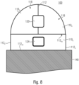
- Fig. 8 shows an embodiment of a sensor element 100 with a basis sensor cell 110 b on which a plurality of mechanically coupled sensor cells 110, are arranged.
- the plurality of mechanically coupled sensor cells 110 u are adjacently arranged on the basis sensor cell 110 b .
- the plurality of mechanically coupled sensor cells 110, on the basis sensor cell 110 b may be arranged as described with respect to one of Figures 1 to 7c , i.e. the plurality of mechanically coupled sensor cells 110, may form a spherical segment or a hemisphere on the basis sensor cell 110 b .
- the basis sensor cell 110 b may have the form of a cylinder, wherein a top wall 112 bu of the basis sensor cell 110 b represents a cell boundary between the basis sensor cell 110 b and the plurality of mechanically coupled sensor cells 110 u , i.e. the top wall 112 bu of the basis sensor cell 110 b may represent a bottom wall or base wall, see 116 in Fig. 1-3 and Fig. 6 , of the plurality of mechanically coupled sensor cells 110 u .
- a flexible spherical segment (hemisphere) subdivided into a plurality of mechanically coupled sensor cells 110 u is positioned on a cylindrical basis sensor cell 110 b .
- the top wall 112 bu of the basis sensor cell 110 b i.e. a cell boundary between the basis sensor cell 110 b and the plurality of mechanically coupled sensor cells 110 u , may be flexible or rigid.
- the side wall 112 b i.e. an outer surface, of the basis sensor cell 110 b , i.e. a wall being perpendicular to the top wall, may be flexible, foldable or rigid.
- the top wall 112 bu and the side wall 112 b of the basis sensor cell 110 b may be flexible. At least one of both, i.e. of the top wall 112 b , and the side wall 112 b , should be flexible.
- the basis sensor cell 110 b may be fluidically coupled to an absolute pressure sensor 124.
- the mechanically coupled sensor cells 110 u may be fluidically coupled to pressure sensor elements 120 as described with regard to Fig. 1 to 7c .
- the at least one pressure sensor element 120 of the mechanically coupled sensor cells 110 comprises only one differential pressure sensor, i.e. only two mechanically coupled sensor cells 110 u are arranged on the basis sensor cell 110 b and both are fluidically coupled to a common differential pressure sensor element 120.
- the basis sensor cell 110 b may comprise an absolute pressure sensor 124.
- the plurality of mechanically coupled sensor cells 110 u may comprise only one or more differential pressure sensors as the one or more pressure sensor elements 120.
- the sensor element 100 may comprise two mechanically coupled sensor cells 110, both fluidically coupled to a common differential pressure sensor element 120.
- each sealed inner volume 118 of the three or more mechanically coupled sensor cells 110 u may be fluidically coupled to two differential pressure sensors, wherein two adjacent mechanically coupled sensor cells 110, share one differential pressure sensor.
- the three mechanically coupled sensor cells 110 shown in Fig.
- the stacking of sensor cells 110 fluidically coupled only to differential pressure sensor elements 120 above a basis sensor cell 110 b with an absolute pressure sensor element 124, allows to determine a horizontal component of a force applied to the sensor element 100 based on pressure information associated with the plurality of mechanically coupled sensor cells 110 u and to determine a vertical component of the force based on pressure information associated with the basis sensor cell 110 b .
- the inventors found that with such a separation of sensor cells for detecting a horizontal force component and one or more sensor cells for detecting a vertical force component in two different layers or levels of the sensor element 100 a high resolution can be achieved.
- the sensor cells 110, on top of the basis sensor cell 110 b are fluidically coupled to absolute pressure sensor elements and/or differential pressure sensor elements, as described with regard to Fig. 1 to Fig. 7c .
- the plurality of mechanically coupled sensor cells 110 cover the complete top wall 112 bu of the basis sensor cell 110 b .
- this is not necessary. It is also possible that the plurality of mechanically coupled sensor cells 110, cover a smaller area or a larger area than an area of the top wall 112 bu of the basis sensor cell 110 b .
- an embodiment may be related to a sensor element 100 with a basis sensor cell 110 b adjacently arranged on the plurality of mechanically coupled sensor cells 110 u , i.e. with the basis sensor cell 110 b being arranged on top of the plurality of mechanically coupled sensor cells 110 u .
- the sensor cells 110 may be formed as, e.g., symmetric and/or equally sized, segments (sectors or sections) of a cylinder.
- the basis sensor cell 110 b may be formed as a spherical segment, hemisphere, spherical dome, cone or truncated cone (frustum).
- the mechanically coupled sensor cells 110 may be fluidically coupled to pressure sensor elements 120 as described with regard to Fig. 1 to 7c .
- the basis sensor cell 110 b is arranged on two mechanically coupled sensor cells 110, fluidically coupled to a common differential pressure sensor element 120.
- the sensor element 100 may be implemented as a stack of two sensor cell layers with different properties, each layer comprising 1D or 2D arrangements of sensor elements (as given in Fig. 4 and 5 ).
- the lower layer comprising the basis sensor cell 110 b is configured for detecting high forces and the upper layer comprising the plurality of mechanically coupled sensor cells 110, is configured for detecting the forces with high resolution.
- Such an embodiment allows for multiscale sensing for enhancing tactile perception.
- the basis sensor cell 110 b is larger than the sensor cells 110 u of the plurality of mechanically coupled sensor cells 110 u , e.g., in terms of the respective cell base area.
- two or more sensor cells 110 with a small cell size, e.g., 5mm 2
- a basis sensor cell 110 b with a larger cell size, e.g., 25mm 2 .
- the exemplary cell sizes enable a maximum of five sensor cells on top of the basis sensor cell 110 b .
- a lower spatial resolution than with the sensor cells 110 u of the plurality of mechanically coupled sensor cells 110 u may be achieved, if the top layer pressure sensor elements 120 have the same cell configuration i.e. as the bottom layer pressure sensor element 124, but at the same time the large basis sensor cell 110 b gets more sensitive to external force loads.
- the sensor element 100 comprises a mounting base 140 on which the basis sensor cell 110 b is arranged, e.g., mounted or fixed.
- a base boundary or a bottom boundary 112 bb of the basis sensor cell 110 b may be fixed to the mounting base 140 or the mounting base 140 may represent the base boundary or the bottom boundary 112 bb of the basis sensor cell 110 b .
- the top wall 112 bu of the basis sensor cell 110 b is arrange opposite to the base boundary or the bottom boundary 112 bb .
- the plurality of mechanically coupled sensor cells 110 u are arranged on a side of the top wall 112 bu facing away from the mounting base 140.
- the basis sensor cell 110 b may be implemented as shown in Fig. 9 with a cell wall 112 b having a nonlinear pressure/force behavior, e.g., by a certain wall geometries, like a folding-structure 150 within the cell wall 112 b , i.e. a foldable outer cover, or by a certain material.
- the folding-structure 150 may completely surround the basis sensor cell 110 b , e.g., being on all sides of the basis sensor cell 110 b , which are perpendicular to the top wall 112 bu .
- the folding-structure 150 may follow a complete circle line around the outer surface of the cylinder.
- each of the four walls being perpendicular to the two wall 112 bu may comprise the folding-structure 150.
- a cell wall, see 112 b for example, is bended twice, e.g., once in a first direction and once in an opposite direction, to form the folding structure 150.
- the bending direction goes along an axis being perpendicular to the top wall 112 bu .
- a cell wall, see 112 b has a bottom-end fixed to a bottom cell boundary or to the mounting base 140 and an upper-end fixed to the top wall 112 b , of the basis sensor cell 110 b .
- a first length of the cell wall 112 bu is directed to the top wall 112 bu
- an adjoining second length of the cell wall 112 bu is directed away from an inner volume of the basis sensor cell 110 b in the direction of the bottom cell boundary or of the mounting base 140 and an adjoining third length of the cell wall 112 bu is directed to the top wall 112 bu again.
- the foldable outer cover i.e. the cell wall 112 b with the folding-structure 150, is configured to provide a folded condition 152 of the basis sensor cell 110 b , when a pressure within the basis sensor cell 110 b exceeds a pressure threshold 154, wherein the folded condition 152 results in a change from a first pressure sensitivity 156 1 to a second, lower, pressure sensitivity 156 2 of the basis sensor cell 110 b .
- the folded condition 152 may result in a change from a first pressure dependency to an increased, second pressure dependency of the basis sensor cell 110 b .
- the sensor element 100 is able to sense low force values, e.g., F ⁇ F thr , with high sensitivity/high resolution, and from a certain load, e.g. threshold value F thr , onwards the sensitivity is decreased to allow for high load measurement.
- F ⁇ F thr low force values
- F thr threshold value
- the principle characteristics are given as simplified drawing in the right side diagram, where the transition between the two regimes can be tuned to be smooth and well defined in order to allow for high measurement performance over increased load force/pressure ranges.
- differential pressure sensors e.g., located at cell boundary walls, i.e. cell boundaries 112
- absolute pressure sensors e.g., located at cell boundary walls, i.e. cell boundaries 112
- a combination of absolute and differential pressure sensors is possible, allowing e.g. highly sensitive measurements, or redundancy in sensible environments (FuSa):
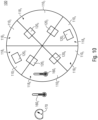
- Fig. 10 shows a sensor element 100 comprising exemplarily six mechanically coupled sensor cells 110, see 110 1 to 110 6 . Further the sensor element 100 comprises exemplarily two absolute pressure sensors 120 1 and 120 2 and four differential pressure sensors 120 3 to 120 6 as its pressure sensor elements 120. Fig. 10 is an example of a sensor element 100 with no redundant pressure sensor elements 120. Features and/or functionalities regarding the housing and the pressure sensor elements 120 may be as described with regard to Fig. 1 - 7c . Optionally, the six mechanically coupled sensor cells 110 shown in Fig. 10 may be arranged on a basis sensor cell 110 b , e.g., as shown in Fig. 8 .
- the sensor element 100 may be comprised by a herein described contact force sensor device 200, e.g., additionally or alternatively to the sensor element 100 shown in Fig. 3 .
- the controller 210 of the contact force sensor device 200 may be configured to combine pressure values obtained/read from the pressure sensor elements 120 of the sensor element 100 of Fig. 10 to determine the contact force 202.
- a sensor cell 110 6 of the mechanically coupled sensor cells 110 comprises a temperature sensor 160 1 for sensing a momentary temperature value in the sensor cell 110 6 .
- two or more sensor cells 110 of the mechanically coupled sensor cells 110 comprise a temperature sensor 160 1 , wherein the respective temperature sensor 160 1 is configured to detect/sense a momentary temperature value in the respective sensor cell 110.
- each of the mechanically coupled sensor cells 110 of the sensor element 100 comprises a temperature sensor 160 1 .
- every pressure sensor element 120 may have a built-in temperature sensor, e.g., for sensor calibration for temperature insensitive pressure sensing. This temperature sensor would be readable by the controller 210, in the same manner as the pressure value of the respective pressure sensor element.
- the basis sensor cell comprises a temperature sensor 160 1 for sensing a momentary temperature value in the basis sensor cell, e.g., a built-in temperature sensor of the absolute pressure sensor element 124.
- the temperature sensor 160 1 within a sensor cell 110 6 improves an accuracy at a determination of a force applied to the sensor element 100. This is based on the idea that a contact with an object with a different temperature or that a change of an ambient temperature changes the pressure within each sensor cell 110, which, for example, is required to be compensated for accurate contact force measurements.. Therefore, the additional information of the momentary temperature value in the respective sensor cell 110 improves an accuracy at the determination of the force.
- the sensor element 100 comprises a temperature sensor 160 2 arranged outside the sensor cells 110, e.g., arranged next to the mechanically coupled sensor cells 110.
- the temperature sensor 160 2 may also be arranged on the mounting base, e.g. in the vicinity of the sensor element 100.
- the temperature sensor 160 2 is configured to provide, e.g., detect or sense, a momentary temperature value of the environmental atmosphere, e.g., surrounding the mechanically coupled sensor cells 110.
- the temperature sensor 160 2 outside of the sensor cells 110 may also improve an accuracy at a determination of a force applied to the sensor element 100. This is based on the idea that an outside temperature has at least partially an influence on a temperature within the sensor cells 110, for example, a hot environment may increase a temperature and thus also a pressure within the sensor cells 110 or a cold environment may reduce a temperature and thus also a pressure within the sensor cells 110. Therefore, the temperature sensor 160 2 outside of the sensor cells 110 allows to calibrate the sensor element 100 for being able to correctly distinguish whether the detected change of a pressure within a sensor cells results from an external force or from a change of the environment. The temperature sensor 160 2 allows to calibrate a reference pressure within the sensor cells 110.
- the sensor element 100 comprises a barometric pressure sensor 170 arranged outside the sensor cells 110, e.g., arranged next to the mechanically coupled sensor cells 110.
- the barometric pressure sensor 170 is configured to provide, e.g., detect or sense, a momentary atmospheric pressure value of the environmental atmosphere.
- the barometric pressure sensor 170 outside of the sensor cells 110 may also improve an accuracy at a determination of a force applied to the sensor element 100. This is based on the idea that a change of an outside pressure may result in change of a force applied to the sensor element 100.
- the barometric pressure sensor 170 allows to compensate for all cell pressure influences from external atmospheric pressure changes.
- the contact force sensor device 200 of Fig. 3 may comprise one of the sensor elements 100 shown in Fig. 6 to 10 , wherein the controller 210 is configured to perform the read out and the determination of the contact force 202 exactly or similarly as described with regard to Fig. 3 .
- Fig. 11 shows an embodiment of a contact force sensor device 200.
- the contact force sensor device 200 is shown on a hand 300 of a robot or on an electronic glove.
- the contact force sensor device 200 can alternatively be implemented in or connected to any other device requesting information regarding contact forces.
- the contact force sensor device 200 shown in Fig. 11 comprises a plurality of sensor elements 100.
- the sensor elements 100 can be fixed to the hand 300 individually or as a one-dimensional or two-dimensional array of sensor elements 100.
- Exemplarily Fig. 11 shows such an array 180 of sensor elements fixed at a tip of the hand 300.
- a plurality of sensor elements 100 could be arranged on a flexible mounting base 140.
- the plurality of sensor elements 100 may form an array 180 of sensor elements 100.
- the contact force sensor device 200 may comprise an array 180 of a plurality of spherically or hemispherically shaped sensor elements 100, each comprising sensor cells formed as segments (sectors) of a spherical segment or a hemisphere.
- one or more of the sensor cells 110 may comprise a temperature sensor 160 1 as described with regard to Fig. 10 .
- the flexible mounting base 140 comprises a flexible wire structure configured to connect the sensor elements 100 with an interface or with the controller 210 of the contact force sensor device 200.
- the flexible mounting base 140 comprising the plurality of sensor elements 100 could represent a mat. Such a mat could then cover a rigid, e.g., a curved, surface like a robotic finger or any kind of application surface.
- the controller 210 may comprise two or more processing units at distributed hierarchy levels.
- the controller 210 may comprise one or more local processing units which are configure for a local processing, e.g., local arrays 180 of sensor elements may be read out by separate local processing units and/or individual sensor elements 100 may be read out by separate local processing units.
- the one or more local processing units may be connected to an overall processing unit, e.g., a high level processing unit or an overall control system, or the one or more local processing units may be connected to a higher level touch / haptic processing unit interfacing two or more sub units, and connecting to the high level processing unit.
- the locality of processing / controller enables significantly reduced wiring.
- the controller 210 of the contact force sensor device 200 is configured to read out a momentary pressure information 204 of the plurality of pressure sensor elements 120 of the plurality of sensor elements 120 and to determine a direction and/or magnitude of a contact force applied to at least parts of the plurality of sensor elements 120 based on the momentary pressure information 204.
- the momentary pressure information 204 may comprise momentary pressure values of plurality of pressure sensor elements 120 of the plurality of sensor elements 120, e.g., as a tensor.
- the momentary pressure information 204 may comprise per sensor element 100, e.g., per array 180 1 of sensor cells 110, and/or per array 180 2 of sensor elements 100 a set of momentary pressure values.
- the momentary pressure information 204 may indicate for each momentary pressure value the associated pressure sensor element from which the respective momentary pressure value has been read.
- the direction and/or magnitude of the contact force may be determined by combining momentary pressure values of the momentary pressure information 204, e.g. as described with regard to Fig. 3 .
- the contact force sensor device 200 comprises a temperature sensor 160, e.g. next to one or more of the plurality of sensor elements 100, for providing a momentary temperature value of the environmental atmosphere.
- the temperature sensor 160 may be arranged, e.g., fixed, on a surface of an object or device, e.g., on the hand 300 of the robot, on which the sensor elements 100, e.g., the array 180 1 of sensor cells 110, and/or the array 180 2 of sensor elements 100 are arranged. It may also be possible that the temperature sensor 160 is arranged on a mounting base 140, see CUT A-A'. Alternatively, it is also possible that the temperature sensor 160 is an external device from which the controller 210 may obtain, e.g.
- the controller 210 is configured to determine the direction and/or magnitude, e.g. strength, of a contact force applied to one or more of the sensor elements 100 based on the read out momentary pressure information 204 and based on the momentary temperature value of the environmental atmosphere.
- the momentary temperature value of the environmental atmosphere for example, is considered for compensating temperature changes or temperature effects in the sensor cells due to a warming or cooling provided by the environmental atmosphere.
- one or more of the sensor cells 110 of the plurality of sensor elements 100 may comprise a temperature sensor, e.g., as described with regard to Fig. 10 , for sensing a momentary temperature value in the sensor cell 110 having the respective temperature sensor.
- the controller is configured to determine the direction and/or magnitude of the contact force applied to one or more of the sensor elements 100 based on the read out momentary pressure information 204 and based on the one or more momentary temperature values in the one or more sensor cell having a temperature sensor.
- the controller may obtain from each sensor cell 110 comprising a temperature sensor a momentary temperature value and consider same at the determination of the direction and/or magnitude of the contact force.
- Such a temperature sensor within a sensor cell is usable for compensating temperature changes or temperature effects in the respective sensor cell.
- the contact force sensor device 200 comprises a barometric pressure sensor 170 next to one or more of the plurality of sensor elements 100 for providing a momentary atmospheric pressure value of the environmental atmosphere.
- the barometric pressure sensor 170 may be arranged, e.g., fixed, on a surface of an object or device, e.g., on the hand 300 of the robot, on which the sensor elements 100, e.g., the array 180 of sensor elements 100, is arranged. It may also be possible that the barometric pressure sensor 170 is arranged on a mounting base 140, see CUT A-A'. Alternatively, it is also possible that the barometric pressure sensor 170 is an external device from which the controller 210 may obtain, e.g.
- the controller 210 receives, the momentary atmospheric pressure value of the environmental atmosphere, e.g., via a wireless connection.
- the controller 210 is configured to determine the direction and/or magnitude, e.g. strength, of the contact force applied to one or more of the sensor elements 100 based on the read out momentary pressure information 204 and based on the momentary atmospheric pressure value of the environmental atmosphere.
- the momentary atmospheric pressure value of the environmental atmosphere is considered for compensating pressure changes in the sensor cells 110 due to a pressure change in the environmental atmosphere.
- the controller 210 may consider, for the determination of the direction and/or the magnitude of the contact force, additionally to the momentary pressure information the momentary temperature value of the environmental atmosphere, one or more momentary temperature values each being associated with a sensor cell having a temperature sensor, and/or the momentary atmospheric pressure value of the environmental atmosphere.
- the controller 210 is configured to determine a distribution of contact forces over a surface area covered by the array 180 of the sensor elements.
- the controller 210 for example, is configured to gain a distribution of vertical forces over the array 180 and/or a distribution of shear force, e.g., components and sum, over the array 180 or a distribution of a 3D contact force distribution over the respective sensor array 180.
- An array 180 of sensor elements 100 enables spatially resolving 3D force sensing.
- the controller 210 is configured to calculate above distributions from sensor cell readouts in a way to obtain high resolution or spatial distributions of mentioned forces.
- the contact force sensor device 200 represents a multi-directional force and touch sensor.
- the herein discussed contact force sensor device 200 is configured to perform tactile and touch sensing in a robust and performant manner, to match into applications from consumer, industrial, and robotics applications.
- the contact force sensor device 200 enables a robust evaluation of touch interactions (feeling) and the measurement of contact forces.
- the contact force sensor device 200 is optimal with respect to application demands, e.g. high performance sensing with touchy human-like perception and/or multi-directional sensing capabilities.
- Combining multi-cell sensors see the herein discussed sensor elements 100, into arrays 180 for local sensing of 3D force distribution in contact area (especially for "soft” or " touchy” sensors) are relevant to cover spatially resolving 3-dimensional touch interactions or tactile condition evaluations.
- the contact force sensor device 200 tackles the measurement of 3-dimensional contact forces on a touch / tactile interface, i.e. the flexible cover 114 of the sensor cells 110, providing 3-dimensional information on contact force arrangement (vertical force with additional shear force components in x-and y-direction) on the surface in contact.
- the contact force sensor device 200 is a novel multidirectional force/touch sensor system composed from a set of sub-cells, i.e. sensor cells 110, interconnected mechanically and/or electrically.
- Each sensor cell 110 may be equipped with pressure sensors 120, e.g., absolute and/or differential pressure sensors. Based on the interconnected sensor principle and by combining the individual pressure measurements a robust and precise estimation of magnitude and direction of 3-dimensional touch forces, i.e. vertical and shear forces, acting on the primary mechanical touch interface, i.e. the flexible cover 114 of the sensor cells 110, is enabled.
- the herein described sensor elements 100 can be arranged within an array.
- Fig. 12a to 12c show examples of 3D Contact Force Sensor Arrays and Fig. 13a and Fig. 13b show 2D Contact Force Sensor Arrays comprising laterally (spatially) separated absolute and shear force sensors.
- the sensor arrays shown in Fig. 12a to 12c may comprise one or more force detection units 2000 configured for detecting a contact force in three dimensions and the sensor arrays shown in Fig. 13a and 13b may comprise one or more force detection units 2000 configured for detecting a contact force in two dimensions.
- Fig. 12a shows a sensor array configured for 3D force sensing by a combination of different sensor elements, e.g., with different cell-units.
- the sensor array for example, comprises one or more single-cell vertical force sensor elements 1000, i.e. one cell with one absolute pressure sensor 1100, and one or more of the herein described sensor elements 100 with at least three mechanically coupled sensor cells 110, e.g., as described with regard to Fig. 4 to Fig. 7c .
- the at least three mechanically coupled sensor cells 110 enable 2D shear force sensing by the respective sensor element 100.
- the pressure sensor elements 120 comprised by the sensor elements 100 represent differential pressure sensor elements, i.e. at each border separating two adjacent sensor cells 110 one of the differential pressure sensor elements is arranged.
- the sensor elements 100 may represent multi-cell shear-force sensor elements, i.e. pure shear-force sensors or pure vertical force sensors, for 2D shear force sensing.
- a force detection unit 2000 of the sensor array shown in Fig. 12a may comprise one single-cell vertical force sensor element 1000 and one sensor element 100 configured for detecting shear force in two dimensions.
- the sensor element 100 for example, may be configured to measure a shear force in a first dimension and in a second dimension, wherein the second dimension is perpendicular to the first dimension.
- the single-cell vertical force sensor element 1000 may be configured to measure a vertical force in a third dimension, wherein the third dimension is perpendicular to the first dimension and the second dimension.
- Fig. 12b and Fig. 12c show examples of an array comprising one or more single-cell vertical force sensor elements 1000, i.e. one cell with one absolute pressure sensor 1100, and two or more of the herein described sensor elements 100 with two mechanically coupled sensor cells 110, e.g., as described with regard to Fig. 1 or Fig. 2 .
- the sensor elements 100 comprise two mechanically coupled sensor cells 110 fluidically coupled to a common differential pressure sensor element, i.e. a two-cell sensor element 100 comprises as pressure sensor element only one differential pressure sensor element.
- the two mechanically coupled sensor cells 110 enable 1D shear force sensing by the respective sensor element 100.
- This sensor elements 100 are used in two variants, wherein a second variant 100 2 is arranged within the array rotated by 90° with respect to the first variant 100 1 .
- This two variants 100 1 and 100 2 together enable a 2D shear force sensitivity of the array.
- the first variant 100 1 may be configured to measure a shear force in a first dimension
- the second variant 100 2 for example, may be configured to measure a shear force in a second dimension, wherein the second dimension is perpendicular to the first dimension.
- the single-cell vertical force sensor element 1000 may be configured to measure a vertical force in a third dimension, wherein the third dimension is perpendicular to the first dimension and the second dimension.
- a force detection unit 2000 of the sensor array shown in Fig. 12b may comprise two single-cell vertical force sensor elements 1000, the first variant 100, of the sensor element 100 and the second variant 100 2 of the sensor element 100.
- the force detection unit 2000 may comprise a 2x2 arrangement of the sensors, i.e. of 1000, 100, and 100 2 .
- each row and column of the 2x2 arrangement may comprise one of the two single-cell vertical force sensor elements 1000 and one of the two variants 100, and 100 2 of the sensor element 100.
- Such a 2x2 arrangement of the sensors improves an accuracy at a detection of a contact force in three dimensions.
- a force detection unit 2000 of the sensor array shown in Fig. 12c may comprise one single-cell vertical force sensor element 1000, the first variant 100, of the sensor element 100 and the second variant 100 2 of the sensor element 100.
- the three sensors may be arranged in form of a triangle within the force detection unit 2000.
- the sensor array shown in Fig. 12c enables a denser arrangement of the sensors compared to the sensor array shown in Fig. 12b .
- a position information of a contact point within the sensor array can be determined more accurately with the sensor array shown in Fig. 12c compared to the sensor array shown in Fig. 12b .
- Fig. 13a and Fig. 13b show examples of an array comprising one or more single-cell vertical force sensor elements 1000, i.e. one cell with one absolute pressure sensor 1100, and one or more of the herein described sensor elements 100 with two mechanically coupled sensor cells 110, e.g., as described with regard to Fig. 1 or Fig. 2 .
- the one or more sensor elements 100 comprise two mechanically coupled sensor cells 110 fluidically coupled to a common differential pressure sensor element, i.e. a two-cell sensor element 100 comprises as the pressure sensor element only one differential pressure sensor element.
- the two mechanically coupled sensor cells 110 enable 1D shear force sensing by the respective sensor element 100.
- Fig. 13a shows a sensor array with sensor elements 100 configured to measure a shear force in a first dimension
- Fig. 13b shows a sensor array with sensor elements 100 configured to measure a shear force in a second dimension, wherein the second dimension is perpendicular to the first dimension.
- the single-cell vertical force sensor element 1000 may be configured to measure a vertical force in a third dimension, wherein the third dimension is perpendicular to the first dimension and the second dimension.
- the sensor array shown in Fig. 13a and the sensor array shown in Fig. 13b are configured to measure a contact force in two dimensions.
- the sensor array shown in Fig. 13a is configured to measure a contact force in the first dimension and in the third dimension and the sensor array shown in Fig.
- a force detection unit 2000 of the sensor array shown in Fig. 13a and 13b may comprise one single-cell vertical force sensor element 1000 and one sensor element 100.
- the simpler arrangements shown in Fig. 13a and 13b might be advantageous in simple lifting applications, i.e. ware handling by grip and lift / relocate objects in industrial robotics.
- Fig. 13a and 13b show variants of the arrangements of the sensors within the respective sensor array.
- the sensors are arranged in rows and columns, which are not shifted/displaced against each other.
- rows of sensors are shifted/displaced against each other.
- the sensor array shown in Fig. 13b enables a denser arrangement of the sensors compared to the sensor array shown in Fig. 13a .
- a position information of a contact point within the sensor array can be determined more accurately with the sensor array shown in Fig. 13b compared to the sensor array shown in Fig. 13a .
- a sensor element comprises a plurality of mechanically coupled sensor cells each having a sealed inner volume within an at least partially flexible cell housing, wherein the flexible cell housing comprises a flexible outer cover and flexible cell boundaries between adjacent sensor cells, and at least one pressure sensor element, wherein each sealed inner volume is fluidically coupled to at least one of the at least one pressure sensor element.
- the sensor element comprises a plurality of the pressure sensor elements comprising absolute pressure sensors, and each sealed inner volume is fluidically coupled to at least one of the plurality of pressure sensor elements, and wherein each sensor cell comprises one of the absolute pressure sensors.
- the at least one pressure sensor element comprises at least one differential pressure sensor, and optionally each sealed inner volume is fluidically coupled to at least one of the at least one differential pressure sensors, and wherein sealed inner volumes of two adjacent mechanically coupled sensor cells are fluidically coupled to a common differential pressure sensor.
- the sensor element comprises a plurality of pressure sensor elements comprising at least one differential pressure sensor and at least one absolute pressure sensor, and each sealed inner volume is fluidically coupled to at least one of the plurality of pressure sensor elements.
- the sensor element comprises two adjacent sensor cells, wherein at least one of the two adjacent sensor cells comprises an absolute pressure sensor and wherein sealed inner volumes of the two adjacent sensor cells are fluidically coupled to a common differential pressure sensor.
- the sensor element further comprises a temperature sensor in at least one of the sensor cells for sensing a momentary temperature value in the sensor cell having the temperature sensor, and/or next to the sensor element for providing a momentary temperature value of the environmental atmosphere.
- the sensor element further comprises a barometric pressure sensor next to the sensor element for providing a momentary atmospheric pressure value of the environmental atmosphere.
- the sensor cells are cube-shaped or cuboid-shaped and arranged in a two-dimensional array, or wherein the sensor cells are formed as segments of a spherical dome.
- the sensor element further comprises a basis sensor cell, wherein the plurality of mechanically coupled sensor cells are adjacently arranged on the basis sensor cell.
- the basis sensor cell comprises a flexible or rigid top wall having arranged thereon the plurality of mechanically coupled sensor cells, and a foldable outer cover, wherein the foldable outer cover is configured to provide an folded condition of the basis sensor cell, when the pressure to the basis sensor cell exceeds a pressure threshold, wherein the folded condition results in a change from a first pressure dependency to an increased, second pressure dependency of the basis sensor cell.
- a contact force sensor device comprises the sensor element, and a controller configured to read out a momentary pressure information of the at least one pressure sensor element of the sensor element and to determine a direction and/or strength of a contact force applied to the sensor element based on the momentary pressure information.
- the contact force sensor device further comprises a temperature sensor in at least one of the sensor cells for sensing a momentary temperature value in the sensor cell having the temperature sensor, and/or next to the sensor element for providing a momentary temperature value of the environmental atmosphere, wherein the controller is configured to determine the direction and/or strength of the contact force applied to the sensor element based on the read out momentary pressure information and based on the momentary temperature value in the sensor cell having the temperature sensor, and/or of the environmental atmosphere.
- the contact force sensor device further comprises a barometric pressure sensor next to the sensor element for providing a momentary atmospheric pressure value of the environmental atmosphere, wherein the controller is configured to determine the direction and/or strength of the contact force applied to the sensor element based on the read out momentary pressure information and based on the momentary atmospheric pressure value of the environmental atmosphere.
- the contact force sensor device further comprises an array comprising the sensor elements, wherein the controller is configured to read out momentary pressure values of the pressure sensor elements of the sensor elements to obtain the momentary pressure information and to determine the direction and/or strength of the contact force applied to the sensor elements based on the read out momentary pressure information.
- the controller is configured to determine a distribution of contact forces over a surface area covered by the array of the sensor elements.
- the contact force sensor device further comprises a cover layer arranged on the array, wherein the cover layer is configured to mechanically couple the sensor elements of the array.
Landscapes
- Physics & Mathematics (AREA)
- General Physics & Mathematics (AREA)
- Chemical & Material Sciences (AREA)
- Analytical Chemistry (AREA)
- Engineering & Computer Science (AREA)
- Human Computer Interaction (AREA)
- Robotics (AREA)
- Mechanical Engineering (AREA)
- Radar, Positioning & Navigation (AREA)
- Remote Sensing (AREA)
- Force Measurement Appropriate To Specific Purposes (AREA)
Abstract
This application concerns a sensor element and a contact force sensor device comprising the sensor element. The sensor element, comprises a plurality of mechanically coupled sensor cells each having a sealed inner volume within an at least partially flexible cell housing. The flexible cell housing comprises a flexible outer cover and flexible cell boundaries between adjacent sensor cells. Further the sensor element comprises at least one pressure sensor element. Each sealed inner volume is fluidically coupled to at least one of the at least one pressure sensor element.
Description
- Embodiments related to a sensor element and a contact force sensor device.
- The robotics market is booming, benefiting from an ever-increasing demand and ever more advanced technologies. With the rise of artificial intelligence (Al), robots are becoming increasingly intelligent and can perform complex interactions with humans and their environments. These interactions are made possible by the ever more refined processing of stimuli from the robot's environment. These stimuli are perceived by sensors. However, if there is a sense that robots do not easily obtain, it is the sense of touch. To succeed in producing soft surfaces capable of perceiving pressure and their directions, temperature, or even pain are the challenges that the robotic skin or e-skin try to answer.
- Tactile sensing for robotic systems - in particular robotic or prosthetic hands or fingers - is a quite complex topic, since requiring:
- a) A huge dynamic range for force/pressure sensing to be able to handle proper sensing of lowest tactile forces/pressures from delicate object interactions and situations (e.g., interaction with an egg or sensing an air flow) up to high forces/applied external pressure (for lifting/carrying heavier objects with robotic arm/fingers)
- b) High spatial sensing resolution to provide recognition of objects and situations
- c) a soft, rubber-like nature to provide proper grip, and to simulate human skin perception
- Existing solutions are based on direct force-sensors, deformation-sensors or piezosensors, each having drawbacks with regard to the above three relevant requirements on tactile solutions for robotic skin/hands.
- The herein described sensor element and contact force sensor device solves for all three requirements on tactile robotic sensing, and, for example, could be extended by AI based sensor fusion/processing locally and/or centrally. Further, the high dynamic range and low power consumption of the herein described sensor element and contact force sensor device are perfectly matching the needs in target applications
- As described above, it is desired to provide a concept which makes a better compromise between increasing a dynamic range for force and/or pressure sensing, increasing a spatial resolution at the force and/or pressure sensing, stimulating as realistically as possible a human skin perception and reducing a power consumption. In addition to robotic use-cases, also other applications like pressure sensitive mats, floors, shoe inlets etc. in consumer, industrial and medical areas are benefitting from the proposed embodiments with soft and highly dynamic spatially resolving touch / pressure sensing.
- This is achieved by the subject matter of the independent claims of the present application.
- Further embodiments are defined by the subject matter of the dependent claims of the present application.
- In accordance with an aspect of the present disclosure, the inventors realized that one problem encountered when trying to detect a force and/or a pressure stems from the fact that most sensors are direct force sensors not sensible for shear forces. According to this aspect of the present disclosure, this difficulty is overcome by providing a sensor element with mechanically coupled sensor cells. For example, the sensor element has an at least partially flexible housing divided into sub-cells by flexible walls. Adjacent sensor cells of the sensor element share a flexible wall/boundary between same. Two adjacent sensor cells may be mechanically coupled via the flexible wall separating the two adjacent sensor cells. This is based on the finding that the mechanical coupling of sensor cells results in high performance multidirectional sensing capabilities. Concurrently, a robust and precise estimation of magnitude and direction of forces acting on the sensor element can be achieved by evaluating a force and/or pressure acting on the individual mechanically coupled sensor cells of the sensor element.
- Accordingly, in accordance with an aspect of the present disclosure, a sensor element comprises a plurality, e.g., two or more, of mechanically coupled sensor cells, e.g., sub-cells, each having a sealed inner volume, e.g., a cavity, within an at least partially flexible cell housing. The flexible cell housing comprises a flexible outer cover and flexible cell boundaries, e.g. walls, between adjacent sensor cells. Further the sensor element comprises at least one pressure sensor element, e.g., one or more pressure sensor elements. Each sealed inner volume is fluidically coupled to at least one of the at least one pressure sensor elements. For example, the sensor element comprises a pressure sensor element and each sealed inner volume is fluidically coupled to the pressure sensor element. According to an embodiment, the sensor element may comprise a plurality of pressure sensor elements and each sealed inner volume is fluidically coupled to one of the plurality of pressure sensor elements.
- Accordingly, in accordance with a further aspect of the present disclosure, a contact force sensor device comprises a herein described sensor element and a controller configured to read out a momentary pressure information of the one or more of pressure sensor elements of the sensor element and to determine a direction and/or strength, e.g., a vector, of a contact force applied to the sensor element based on the momentary pressure information.
- The drawings are not necessarily to scale, emphasis instead generally being placed upon illustrating the principles of the embodiments. In the following description, various embodiments are described with reference to the following drawings, in which:
- Fig. 1
- shows an embodiment of a two-cell sensor element with two absolute pressure sensors;
- Fig. 2
- shows an embodiment of a two-cell sensor element with a differential and an absolute pressure sensor;
- Fig. 3
- shows an embodiment of a contact force sensor device;
- Fig. 4
- shows an embodiment of a one dimensional array of sensor elements;
- Fig. 5
- shows an embodiment of a two dimensional array of sensor elements;
- Fig. 6
- shows an embodiment of a hemispherical sensor element;
- Fig. 7a
- shows an embodiment of a hemispherical sensor element with absolute pressure sensors;
- Fig. 7b
- shows an embodiment of a hemispherical sensor element with absolute and differential pressure sensors;
- Fig. 7c
- shows an embodiment of a hemispherical sensor element with redundant pressure sensors;
- Fig. 8
- shows an embodiment, of a sensor element with stacked sensor cells;
- Fig. 9
- shows an embodiment of a basis sensor cell with a foldable-structure;
- Fig. 10
- shows an embodiment of a hemispherical sensor element with temperature sensor and/or barometric sensor;
- Fig. 11
- shows an embodiment of a contact force sensor device with a plurality of sensor elements;
- Fig. 12a
- shows an embodiment of a sensor array configured for 3D force sensing;
- Fig. 12b
- shows an embodiment of a sensor array configured for 3D force sensing with an nxn force detection unit;
- Fig. 12c
- shows an embodiment of a sensor array configured for 3D force sensing with a force detection unit in form of a triangle;
- Fig. 13a
- shows an embodiment of a sensor array configured for 2D force sensing; and
- Fig. 13b
- shows an embodiment of a dense sensor array configured for 2D force sensing.
- Equal or equivalent elements or elements with equal or equivalent functionality are denoted in the following description by equal or equivalent reference numerals even if occurring in different figures.
- In the following description, a plurality of details is set forth to provide a more throughout explanation of embodiments. However, it will be apparent to those skilled in the art that embodiments may be practiced without these specific details. In other instances, well-known structures and devices are shown in block diagram form rather than in detail in order to avoid obscuring embodiments. In addition, features of the different embodiments described herein after may be combined with each other, unless specifically noted otherwise.
- In the description of the embodiments, terms and text passages placed in brackets (next to a described element or function) are to be understood as further explanations, exemplary configurations, exemplary additions and/or exemplary alternatives of the described element or function.
- For facilitating the description of the different embodiments, some of the figures comprise a Cartesian coordinate system x, y, z, wherein the x-y-plane corresponds, i.e. is parallel, to a first main surface region of a substrate (= a reference plane = x-y-plane), wherein the direction vertically up with respect to the reference plane (x-y-plane) corresponds to the "+z" direction, and wherein the direction vertically down with respect to the reference plane (x-y-plane) corresponds to the "-z" direction. In the following description, the term "lateral" means a direction parallel to the x- and/or y-direction, i.e. parallel to or in the x-y-plane, wherein the term "vertical" means a direction parallel to the z-direction.
- The term "flexible" may be understood in this disclosure as reversibly or elastically deformable. For example, a flexible (elastic) object, like a wall, a boundary, a cap or a cover, is deformable and returns to its original position/initial position (initial state) after a deformation.
-
Figures 1 to 7c andFig. 10 describe exemplarily asensor element 100 with at least two mechanically coupledsensor cells 110 and at least twopressure sensor elements 120. For each of the at least two mechanically coupledsensor cells 110, the respective sealedinner volume 118 is fluidically coupled to at least one of the at least twopressure sensor elements 120. This implementations are described in order to facilitate the understanding of the underlying concept. Furthermore, as will be described in more detail with regard toFig. 8 andFig. 12b to 13b , it is alternatively possible that thesensor element 100 comprises aspressure sensor element 120 only one differential pressure sensor element. For example, thesensor element 100 may comprise two mechanically coupled sensor cells each one fluidically coupled to the differential pressure sensor element. -
Fig. 1 andFig. 2 show exemplarily asensor element 100, e.g., a cell, with twosensor cells respective sensor element 100 is shown on the left and a side view of therespective sensor element 100 is shown on the right. - The
sensor element 100 may have an at least partially flexible housing comprising aflexible cover 114, see theflexible cell cover 114, of thefirst sensor cell 1101 and theflexible cell cover 1142 of thesecond sensor cell 1102 and a ground orbase 116, see thecell boundaries base 116 of the at least partially flexible housing may be flexible or rigid. Theflexible cover 114 may also be understood as a flexible outer cover. - An inner volume of the at least partially flexible housing is divided by a
flexible cell boundary 112 into two sealed inner volumes. In other words, theflexible cell boundary 112 divides thesensor element 100 into the twosensor cells flexible cell boundary 112 is arranged between the twoadjacent sensor cells flexible cell boundary 112 is shared between the twosensor cells sensor cells flexible cell boundary 112. Thefirst sensor cell 1101 has a cell housing comprising a flexible outer cover, see theflexible cell cover 1141, and theflexible cell boundary 112. Thesecond sensor cell 1102 has a cell housing comprising a flexible outer cover, see theflexible cell cover 1142, and theflexible cell boundary 112. - The
sensor element 100, for example, has the shape of a spherical segment or a hemisphere, e.g., a semi-sphere or half-sphere or a spherical dome, and thesensor cells 110 represent subdivisions of the spherical segment (hemisphere), e.g., the spherical segment (hemisphere) may be subdivided into, e.g., equally sized, compartments representing thesensor cells 110. Thesensor cells 110 may be formed as, e.g., symmetric and/or equally sized, segments (sectors or sections) of a spherical dome. The spherical dome, for example, comprises a spherical cap, i.e. theflexible cover 114, on a circular base area, see thebase 116, or on a circular footprint of thesensor element 100. Worth mentioning is that in case of spherical- or rotational-symmetric sensor cell arrangements the estimation of force directions, e.g., by thecontroller 210 of the contactforce sensor device 200 shown inFig. 3 , is easier, having unidirectional sensitivities for the individual force components. - The
sensor cells 110 of the herein describedsensor elements 100 have exemplarily the shape of a spherical segment or the shape of a segment of a hemisphere, but another shape would also be possible, such as cube-shaped, cuboid-shaped, toroid-shaped (ring-shaped), cylinder-shaped or cone-shaped, for example. The description is equally applicable tosensor elements 100 having the shape of a cube, cuboid, toroid, a cylinder or a cone, for example. -
Sensor elements 100 having the shape of a spherical segment or being cone-shaped have the advantage that same provide a smaller contact area than flat sensor elements, like cube-shaped, cuboid-shaped, toroid-shaped (ring-shaped) or cylinder-shapedsensor elements 100. The contact area, e.g., a top area, e.g., an area opposite to thebase 116, distributes a contact force to the cells underneath. The dome-like shape of asensor element 100 distributes a force vector on the contacting top area into shape changes and thus different pressure values in the individual sub-cells, i.e. sensor cells. It has been found that it is advantageous, when the top contact area of asensor element 100 is smaller than the bottom area of thesensor element 100. The smaller contact area improves an accuracy at a determination of a direction of the contact force, since a dependency of a deformation of theflexible cover 114 from a shape of an object applying the contact force onto thesensor element 100 is significantly reduced. For example, at flat sensor elements 100 a direction reading, i.e. a determined direction of a contact force, could be erroneous when a tilted surface is pressed against a flat cover of the sensor elements, since this may also result in different pressure values in the sensor cells of thesensor element 100, even if the force is only applied vertically from above and has no force component parallel to the base area, see 116. - In contrast,
flat sensor elements 100, e.g., with a 1D or 2D array of identical single cubic cells or acylindrical sensor element 100, have shortcomings with regard to shear force measurement, e.g. in addition to contact force measurement.Such sensor elements 100 would only measure contact force per cell, which might be sufficient for much simpler applications. Forsuch sensor elements 100 one would either chose only absolute pressure sensors, or absolute and differential pressure sensors mixed in a way that each cell pressure can be sensed with sufficient accuracy. - As will be described in more detail with regard to
Fig. 3 , thesensor cells sensor element 100 are mechanically coupled. Mechanically coupled, for example, means that a deformation of one of the two mechanically coupled sensor cells, e.g. of 1101 or 1102, may have an impact on the other sensor cell, like a deformation of the other sensor cell. For example, an external force applied to one of the two adjacent sensor cells may deform theflexible cover sensor cells flexible cell boundary 112 between the twosensor cells - The cell housings may be impermeable to fluids. For example, the
sensor cells sensor cell adjacent sensor cells adjacent sensor cells - Further, the
sensor element 100 comprises a plurality ofpressure sensor elements 120, e.g. pressure sensor units, i.e. twopressure sensor elements pressure sensor elements Fig. 1 andFig. 2 on the right, may be arranged at the bottom 116, see 116, and 1162, of the housing of therespective sensor element 100. InFig. 1 thesensor element 100 comprises two absolutepressure sensor elements Fig. 2 thesensor element 100 comprises one absolutepressure sensor element 1201 and one differentialpressure sensor element 1202. - The
sensor elements 100 shown inFig. 1 andFig. 2 are configured for unidirectional shear force sensing. Having two sensor cells, thesensor element 100 may be capable to sense shear forces along oneaxis 130, e.g., in only one direction. Theaxis 130 may be perpendicular to thecell boundary 112 between the twoadjacent sensor cells cell boundary 1124 in an non-deformed state. Thesensor elements 100 shown inFig. 1 andFig. 2 may be configured to sense lateral forces, e.g., shear forces at a sensor interface, i.e. at a top of theflexible cover 114. Additionally, thesensor element 100 is sensitive for vertical forces, i.e. forces perpendicular to thecover 114. Thissensor elements 100, for example, can be fixed to a mechanical grip element to detect efficiently and with high accuracy whether an object is properly griped or whether the object slips, i.e. as a stick-slip sensor on mechanical grip elements. The two-cell sensor element 100 might be advantageous in situations where only one-directional shear force is relevant, i.e. gripping and lifting of objects, since shear force would only appear in lateral direction. The two-cell sensor would then be sufficient, but be much simpler and cheaper to manufacture, realize and operate than a sensor element with three or more sensor cells, as shown inFig. 4 to 10 . -
Fig. 1 shows an embodiment, where the plurality ofpressure sensor elements 120 represent absolute pressure sensors. Thesensor element 100, for example, comprises only absolute pressure sensors and eachsensor cell 110 comprises one of the absolute pressure sensors, i.e. each sealedinner volume 118 is fluidically coupled to one of the plurality of pressure sensor elements. As shown inFig. 1 the first sealedinner volume 1181 of thefirst sensor cell 1101 is fluidically coupled to a first absolutepressure sensor element 1201 and the second sealedinner volume 1182 of thesecond sensor cell 1102 is fluidically coupled to a second absolutepressure sensor element 1202. - Generally speaking, the plurality of
pressure sensor elements 120 may comprise a plurality of absolute pressure sensor elements and eachsensor cell 110 of asensor element 100 may comprise one of the absolutepressure sensor elements 120 fluidically coupled to the sealedinner volume 118 of therespective sensor cell 110. - The
sensor element 100 may be configured to detect an external force applied to thesensor element 100, e.g., a force applied to theflexible cover 114, i.e. to theflexible cell cover 114, of thefirst sensor cell 110, and/or to theflexible cell cover 1142 of thesecond sensor cell 1102, by detecting for eachsensor cell inner volume 1181/1182 of therespective sensor cell 1101/1102 by the respectivepressure sensor element 1201/1202. In other words, in bothadjacent sensor cells pressure sensor element 1201/1202 may be coupled to the respective sealedinner volume 1181/1182 in order to evaluate the pressure of both cells individually. Thesensor element 100 is configured to obtain a momentary pressure information comprising a first absolute pressure value obtained from the first absolutepressure sensor element 1201 and a second absolute pressure value obtained from the second absolutepressure sensor element 1202. A pressure difference between the two adjacent sensor cells, see thefirst sensor cell 1101 and thesecond sensor cell 1102, is determinable, e.g. by thecontroller 210 inFig. 3 , based on the absolute pressure values obtained from the absolute pressure sensors of the two adjacent sensor cells. The absolute pressure values and the pressure difference may be an indication for a magnitude and direction of an external force applied to thesensor element 100. - According to an embodiment, the
sensor element 100 may comprises a combination of at least one absolute pressure sensor and at least one differential pressure sensor. For example, the plurality ofpressure sensor elements 120 comprises one or more absolute pressure sensors and one or more differential pressure sensors.Fig. 2 , for example, shows an embodiment, with one absolutepressure sensor element 1201 and one differentialpressure sensor element 1202. The first sealedinner volume 1181 of thefirst sensor cell 1101 is fluidically coupled to the absolutepressure sensor element 1201 and to the differentialpressure sensor element 1202 and the second sealedinner volume 1182 of thesecond sensor cell 1102 is fluidically coupled to thedifferential pressure sensor 1202. The differentialpressure sensor element 1202 is fluidically coupled to the sealedinner volume 1181 of thefirst sensor cell 1101 and to the sealedinner volume 1182 of thesecond sensor cell 1102. For example, each sealed inner volume, see 1181 and 1182, is fluidically coupled to the differentialpressure sensor element 1202. - Generally speaking, a differential
pressure sensor element 1202 may be fluidically coupled to the sealedinner volumes adjacent sensor cells 110 of asensor element 100 for evaluating a pressure difference. The differentialpressure sensor element 1202 crosses theflexible cell boundary 112 between theadjacent sensor cells Adjacent sensor cells cell boundary 112 or being separated by acell boundary 112. The differentialpressure sensor element 1202 may be fluidically coupled to the two sealedinner volumes cell boundary 112. - Generally speaking a herein described
sensor element 100 may comprise two adjacent sensor cells, e.g., 1101 and 1102 inFig. 2 ,7b or 7c , wherein at least one of the twoadjacent sensor cells Fig. 2 and 1202 inFig. 7b and 7c , of the at least one absolute pressure sensors. For example, referring toFig. 2 , a sealed inner volume, see 1181, of a first sensor cell, see 1101, of the two adjacent sensor cells is fluidically coupled to the absolute pressure sensor. Further, sealed inner volumes, see 1181 and 1182, of the twoadjacent sensor cells differential pressure sensor 1202 of the at least one differential pressure sensors, i.e. to a common differential pressure sensor. The differential pressure sensor is fluidically coupled to the sealedinner volume 1181 of thefirst sensor cell 110 of the twoadjacent sensor cells 110 and to the sealedinner volume 1182 of asecond sensor cell 110 of the twoadjacent sensor cells 110. A number of thesensor cells 110 may be two, e.g., thesensor element 100 comprises the twoadjacent sensor cells Fig. 2 . Alternatively, thesensor element 100 may comprise additionally to the twoadjacent sensor cells sensor cells 100 fluidically coupled to at least one of the plurality ofpressure sensor elements 120, as shown inFig. 7b and 7c . - The
sensor element 100 shown inFig. 2 may be configured to detect an external force applied to thesensor element 100, e.g., a force applied to theflexible cover 114, i.e. to theflexible cell cover 1141 of thefirst sensor cell 110, and/or to theflexible cell cover 1142 of thesecond sensor cell 1102, by detecting an absolute pressure within the fluid sealed within the first sensor cell using the absolutepressure sensor element 1201 and by detecting a pressure difference between fluids sealed within the two adjacent sensor cells, i.e. between thefirst sensor cell 1101 and thesecond sensor cell 1102, using the differentialpressure sensor element 1202. An absolute pressure within thesecond sensor cell 1102 is determinable, e.g. by thecontroller 210 inFig. 3 , based on the absolute pressure value obtained from theabsolute pressure sensor 1201 and based on the pressures difference obtained from thedifferential pressure sensor 1202. A combination of the absolute pressure value and the pressure difference may be an indication for a magnitude and/or a direction of an external force applied to thesensor element 100. - Optionally, the
second sensor cell 1102 may also comprise an absolute pressure sensor. This results in redundancy, i.e. thesensor element 100 comprises redundant pressure sensor elements. Such an embodiment may be especially advantageous in sensible environments, since a high accuracy and/or high robustness is achieved. - The embodiments of the
sensor element 100 shown inFig. 1 andFig. 2 have the advantage that same enable a determination of a direction and a magnitude of a force applied to therespective sensor element 100. With thesensor elements 100 shown inFig. 1 andFig. 2 it is possible to detect vertical and horizontal forces. - A contact
force sensor device 200, e.g., as shown inFig. 3 orFig. 11 , may comprise one or more of the herein describedsensor elements 100 in order to determine or evaluate acontact force 202 applied to the one ormore sensor elements 100, i.e., to measure vertical and/or shear force at a contact point. The read out of the at least twopressure sensor elements 120 of thesensor element 100 or of thepressure sensor elements 120 of two ormore sensor elements 100 and the determination of thecontact force 202, e.g., a direction and a strength of thecontract force 202, like a vector, may be performed by acontroller 210 comprised by the contactforce sensor device 200. -
Fig. 3 shows schematically a contactforce sensor device 200 comprising exemplarily thesensor element 100 ofFig. 1 and acontroller 210. However, the contactforce sensor device 200 may alternatively comprise any other herein describedsensor element 100 or combination ofsensor elements 100. - The
controller 210 is configured to read out the plurality of pressure sensor elements, i.e. the firstpressure sensor element 1201 and the secondpressure sensor element 1202, of thesensor element 100 to obtain amomentary pressure information 204. Themomentary pressure information 204 comprises one or more pressure values read from the plurality ofpressure sensor elements 120. In case of the embodiment shown inFig. 3 , for example, thecontroller 210 is configured to obtain afirst pressure value 1221 associated with thefirst sensor cell 1101, e.g., by reading out the firstpressure sensor element 1201, and/or asecond pressure value 1222 associated with thesecond sensor cell 1102, e.g., by reading out the secondpressure sensor element 1202. - In case of the
sensor element 100 being the one shown inFig. 2 , themomentary pressure information 204 comprises, e.g., represents, two pressure value, i.e. an absolute pressure read from theabsolute pressure sensor 1201 and a pressure difference read from thedifferential pressure sensor 1202. - Generally speaking, the
momentary pressure information 204 may comprise for each of the at least twopressure sensor elements 120 of a herein described sensor element 100 a pressure value. Themomentary pressure information 204 may comprise a vector of two or more pressure values, each of which is associated with one of the two or morepressure sensor elements 120. If no pressure, e.g. no absolute pressure or no pressure difference, is detected by apressure sensor element 120 of the plurality, e.g., two or more, ofpressure sensor elements 120, the respective read outpressure value 122 may be zero. It may also be possible, that themomentary pressure information 204 comprises only pressure values unequal to zero together with an indication of thepressure sensor element 120 from which the respective pressure value is read out. - The
sensor element 100 may comprise within itsbase wall 116, e.g. a wall opposite to thecover 114 of thesensor element 100, an electronic circuit and/or an interface for providing one or more pressure values detected by the at least onepressure sensor element 120. The at least onepressure sensor element 120 is arranged on, e.g., fixed to, an inner surface of thebase wall 116, i.e. a surface facing the sealed inner volume, see 1181 and 1182. Optionally, thecontroller 210 is embedded or integrated within thebase wall 116 and connected to eachpressure sensor element 120 of thesensor element 100 via the electronic circuit. - According to an embodiment, the
sensor element 100 comprises a mounting base. Thesensor cells 110, for example, are arranged, e.g., fixed, in or on the mountingbase 140, e.g., seeFig. 6 ,Fig. 8 ,Fig. 9 andFig. 11 . The mountingbase 140, for example, comprises the electronic circuit and/or the interface. Optionally thecontroller 210 is embedded or integrated within the mountingbase 140 and, for example, connected to eachpressure sensor element 120 of thesensor element 100 via the electronic circuit. - In case of an interface, e.g., a communication link, being comprised by the base wall or the mounting
base 140, the interface may be configured to transmit themomentary pressure information 204 on a transmission medium such as a wireless transmission medium or a wired transmission medium to thecontroller 210. The transmission medium, for example, is a wired or wireless connection based on, e.g., I2C, SPI, Bluetooth, BLE, etc. - According to an embodiment the
controller 210 can be located local to, e.g., in the vicinity of, the one ormore sensor elements 100. Additionally, or alternatively, it may be possible that thecontroller 210 comprises two or more processing units at distributed hierarchy levels, e.g. a combination of one or more local processing units, e.g., persensor element 100 or for a set of locally grouped/clustered sensor elements 100 (e.g., at a finger tip area), and an upper layer processing unit configured to obtain signals from the one or more local processing units. Thecontroller 210 may comprise two or more upper layer processing units, each one configured to obtain signals from a different set of one or more local processing units, and an overall processing unit configured to obtain signals from the two or more upper layer processing units. An upper layer processing unit may be configured to obtain one or more signals from the associated local processing units to combine / process and/or distribute the one or more signals to the overall processing unit. - The
controller 210 is configured to determineinformation 212 regarding a direction and/or a strength, e.g., a vector, of thecontact force 202 applied to thesensor element 100 based on themomentary pressure information 204. For example, avertical component 202z of thecontact force 202 may be determined based on a sum of the absolute pressure value, see 1221, read out from the absolute pressure sensor element comprised by thefirst sensor cell 1101, see 1201, and the absolute pressure value, see 1222, read out from the absolute pressure sensor element comprised by thesecond sensor cell 1102, see 1202. Ahorizontal component 202x of thecontact force 202 may be determined based on a difference between the absolute pressure value, see 1221, read out from the absolute pressure sensor element comprised by thefirst sensor cell 1101, see 1201, and the absolute pressure value, see 1222, read out from the absolute pressure sensor element comprised by thesecond sensor cell 1102, see 1202. Thedetermined information 212 may comprise thevertical component 202z and thehorizontal component 202x, e.g., as a vector. - In case of the
sensor element 100 being the one shown inFig. 2 , thecontroller 210 may be configured to determine thehorizontal component 202x of the contact force 220 based on the pressure difference pdiff read from the differential pressure sensor, see 1202. Thevertical component F z 202z can be determined based on the absolute pressure value pabs read from the absolute pressure sensor, see 1201, and the pressure difference pdiff read from the differential pressure sensor, see 1202, e.g. Fz ~ (2 · pabs + pdiff ). Thus, thedetermined information 212 may comprise thevertical component 202z and thehorizontal component 202x, e.g., as a vector. - Generally speaking, the
controller 210 may be configured to combine pressure values comprised by themomentary pressure information 204 to determine thevertical component 202z and/or thehorizontal component 202x of thecontact force 202, i.e. combine momentary pressure values read out of two or morepressure sensor elements 120 to determine the direction and/or strength of thecontact force 202. - As shown in
Fig. 3 , theouter cover 1141 of the firstsensor sensor cell 1101 and theouter cover 1142 of thesecond sensor cell 1102 of thesensor element 100 are flexible, i.e. deformable by an external force, e.g. thecontract force 202. A deformation of asensor cell 110, see 1101 and 1102, may result in a change of a pressure within therespective sensor cell 110, e.g. compared to a reference pressure associated with anon-deformed sensor cell 110, i.e. a pressure within the sealedinner volume 118, see 1181 and 1182, of therespective sensor cell 110 when same is not deformed. Due to thesensor cells 110 of thesensor element 100 being mechanically coupled, a deformation of a sensor cell, see 1102, onto which thecontact force 202 is applied may also result in a deformation of sensor cells, see 1101, neighboring thesensor cell 1102 onto which thecontact force 202 is applied. In other words, thesensor cell 1102 onto which thecontact force 202 is applied and the neighboring mechanically coupled sensor cell, see 1101, are deformed by thecontact force 202. The mechanical coupling of thesensor cells 110 allows a two-dimensional evaluation of thecontact force 202 by asensor element 100 with a one-dimensional arrangement of itssensor cells 110, e.g., compareFig. 1 and2 , and a three-dimensional evaluation of thecontact force 202 by asensor element 100 with a two-dimensional arrangement of itssensor cells 110, e.g., compareFig. 4-10 . -
Fig. 1 to 3 show exemplarily asensor element 100 with twosensor cells Fig. 4 to 10 . It is possible that asensor element 100 comprisesn sensor cells 110, wherein n is an integer equal to or greater than 2, 3, 5 or 10. -
Fig. 3 shows exemplarily a contactforce sensor device 200 with onesensor element 100. Alternatively, it is also possible, that the contactforce sensor device 200 comprises two ormore sensor elements 100, e.g. arranged in a one-dimensional array, seeFig. 4 , or arranged in a two-dimensional array, seeFig. 5 . -
Fig. 4 shows an embodiment of a one-dimensional array of sensor elements, see 1001 to 1004, i.e. thesensor elements 100 are arranged in form of a one-dimensional array.Fig. 4 shows exemplarily, a one-dimensional array ofdifferent sensor elements 100. Alternatively, a one-dimensional array ofidentical sensor elements 100, i.e. of sensor elements of the same type, is also possible. As can be seen inFig. 4 , thesensor elements 100 of the one-dimensional array can differ among each other in a number of sensor cells comprised by each sensor element and/or in a number and/or arrangement ofpressure sensor elements 120 of eachsensor element 100. -
Fig. 5 shows an embodiment of a two-dimensional array of sensor elements, see 100, to 1004, i.e. thesensor elements 100 are arranged in form of a two-dimensional array.Fig. 5 shows exemplarily a two-dimensional array ofidentical sensor elements 100, i.e. ofsensor elements 100 of the same type. Alternatively, the two-dimensional array can comprise sensor elements differing among each other, e.g., in a number of sensor cells and/or in a number and/or arrangement ofpressure sensor elements 120. Exemplarily, thesensor elements 100 comprise foursensor cells 110, alternatively, it is possible that another number ofsensor cells 110 can be comprised by thesensor elements 100. The two-dimensional arrangement can comprisenxn sensor elements 100 ornxm sensor elements 100, wherein n is an integer equal to or greater than 2, 3, 5 or 10 and wherein m is an integer equal to or greater than 2, 3, 5 or 10. In case ofnxm sensor elements 100 the integer n is unequal to the integer m. - It might be advantageous, if a one-dimensional array of
sensor elements 100, seeFig. 4 , or a two-dimensional array ofsensor elements 100, seeFig. 5 , comprises two ormore sensor elements 100 of a first type of sensor elements and two or more sensor elements of a second type of sensor elements. The first type ofsensor elements 100 may differ from the second type ofsensor elements 100 in a number of sensor cells and/or in a number and/or arrangement ofpressure sensor elements 120. A type of asensor element 100 may define a number ofsensor cells 110 of thesensor element 100 and/or a number and/or arrangement ofpressure sensor elements 120 of thesensor element 100. -
Fig. 4 showsexemplarily sensor elements 100 with different pressure sensor element numbers and arrangements. On the contrary,Fig. 5 showsexemplarily sensor elements 100 with the same number and arrangement ofpressure sensor elements 120. Different configurations are possible for eachsensor element 100 of the one-dimensional or two-dimensional arrangement of sensor elements, like only absolute pressure sensors or a combination of absolute pressure sensors and differential pressure sensors. - The arrangement of a plurality of
sensor elements 100, e.g., as shown inFig. 4 and5 , in a one-dimensional or two-dimensional arrangement enables a monitoring of a large area. With such arrangements it may be possible to detect and evaluate with a herein discussed contact force sensor device 200 a plurality of forces applied to the array ofsensor elements 100. The two-dimensional arrangement ofFig. 5 may be designed/formed as a mat of a plurality ofsensor elements 100. Thecontroller 210 ofFig. 3 may be configured to, based on pressure values received from a plurality ofpressure sensor elements 120 of the mat of plurality ofsensor elements 100, determine a two-dimensional force field, e.g., a vector field, showing at least one force applied to the mat, i.e. to thesensor element 100 arranged on the mat. The two-dimensional force field may indicate a location and a magnitude and/or a direction of at least one force within a two-dimensional area, i.e. within the two-dimensional area spanned by thesensor elements 100. - The one-dimensional or two-dimensional arrangement of
sensor elements 100 may be configured to detect and evaluate a plurality of forces applied to one or more of thesensor elements 100 of the one-dimensional or two-dimensional arrangement. It might be advantageous, if the one-dimensional arrangement ofsensor elements 100 comprises at least 5, 10, 20 or 30sensor elements 110 in a row, as described with regard toFig. 4 , or if the two-dimensional arrangement ofsensor elements 100 comprises nxn ornxm sensor elements 100 with n being an integer equal to or greater than 5, 10, 20 or 30 and with m being an integer equal to or greater than 5, 10, 20 or 30, as described with regard toFig. 5 . In this case, for example, pressure values associated with different parts of the arrangement may be considered by thecontroller 210 ofFig. 3 to determine a magnitude and/or direction of forces applied to the different parts. For example, thecontroller 210 may be configured to identify within an area of the one-dimensional or two-dimensional arrangement of sensor elements 100 asensor element 110 providing the highest pressure value, e.g., highest absolute pressure or highest pressure difference, and base the determination of the magnitude and/or direction of the force on pressure values associated withsensor elements 100 surrounding the identifiedsensor element 100, i.e. thesensor elements 100 associated with the highest pressure value, e.g., pressure values associated with the next and the next-but-one sensor element with respect to the identified sensor element may be taken into account. Pressure values associated withsensor elements 100 located within a further area of the one-dimensional or two-dimensional arrangement ofsensor elements 100 may be considered similarly to determine a further force applied in the further area. - The
controller 210 of the contactforce sensor device 200 shown inFig. 3 may analyze acontact force 202 applied to one or more of thesensor elements 100 shown inFig. 4 or5 by evaluating pressure values of eachsensor element 100 individually, as described with regard toFig. 3 , or by combining pressure values of two ormore sensor elements 100. The plurality ofsensor elements 100 may be connected to thecontroller 210. - The plurality of
sensor elements 100 may be configured to cover a mat or an area of a device, like a finger area of a robot in a one-dimensional or two-dimensional arrangement. For example, the plurality ofsensor elements 100 may be arranged on, e.g., fixed to, a common mounting base. Thecontroller 210 may be configured to read out pressure values of each of the plurality ofsensor elements 100, for example, eachsensor element 100 may be configured to provide a momentary pressure information comprising one or more pressure values associated with the one or morepressure sensor elements 120 of therespective sensor element 100. Further, thecontroller 210 may be configured to determine a direction and/or a strength and/or a position of a force contact point on the one-dimensional or two-dimensional arrangement of sensor elements of one or more contact forces applied to the plurality ofsensor elements 100 based on the momentary pressure information. - Optionally, the contact
force sensor device 200 comprises a flexible cover layer arranged on the plurality ofsensor elements 100, e.g., on top of the array, i.e. on the one-dimensional arrangement or the two-dimensional arrangement ofsensor elements 100, e.g., covering the plurality ofsensor elements 100. The flexible cover layer may be configured to mechanically couple the plurality ofsensor elements 100. A force applied to the flexible cover layer may be distributed overseveral sensor elements 100 of the plurality ofsensor elements 100. This increases a resolution for location, but reduces measuring the contact area (locality) over the array. This might be useful for specific use-cases, e.g. touch panels. Similarly the flexible cell covers 114 of thesensor cells 110 of asensor element 100 may be configured to distributed an applied force overseveral sensor cells 110 of therespective sensor element 100. This increases an accuracy and/or robustness at a force determination using therespective sensor element 100. -
Figures 1 to 5 already show that a herein describedsensor element 100 can be realized with different numbers ofsensor cells 110 and with different arrangements of the two ormore pressure sensors 120. With regard to the followingFigures 6 to 7c implementation options with regard to the numbers ofsensor cells 110 and with regard to possible different arrangements of the two ormore pressure sensors 120 are described in more detail. The features and/or functionalities described with regard to thesensor elements 100 inFig. 1 to 5 are also applicable to thesensor elements 100 inFig. 6 to 7c and also the other way around. This applies especially with regard to the at least twopressure sensor elements 120 within thesensor element 100, with regard to thebase 116, i.e. a bottom sensor wall, with regard to a mountingbase 140 and with regard to an implementation of therespective sensor element 100 within the contactforce sensor device 200 inFig. 3 , i.e. with regard to a read out of the pressure values and a determination of thecontact force 202. -
Fig. 6 shows exemplarily thesensor element 100 in form of a spherical segment or a hemisphere once in a side view on the left and once in a top view on the right. Thesensor element 100 comprises exemplarily four mechanically coupledsensor cells 1101-4, e.g., just like thesensor elements 100 shown inFig. 5 or as thesensor elements Fig. 4 . Alternatively, another number ofsensor cells 110 could be implemented. For example, the spherical segment (hemisphere) could be subdivide into two halves, i.e. asensor element 100 with twosensor cells 110 like the one shown inFig. 1 andFig. 3 . Embodiments of thesensor element 100 in form of a spherical segment or hemisphere with three sensor cells can be seen inFig. 7a to Fig. 7c and inFig. 4 (see 1002 inFig. 4 ). Generally speaking, thesensor element 100 in form of a spherical segment or a hemisphere may comprisen sensor cells 110, wherein n is an integer equal to or greater than 2. An upper limit for the number ofsensor cells 110 may depend on an area of a circle spanned by the spherical segment or the hemisphere, i.e. on a size of abase area 116 of thesensor element 100. The upper limit ofsensor cells 110 may be 3, 4 or 6. - Each
sensor cell 110, see 1101-4, has a sealedinner volume 118, see 1181-4, within an at least partially flexible cell housing. Thesensor cells 110, for example, are filled with either gas or liquid, easily done in a way to show the same initial pressure for unloaded conditions. The flexible cell housing, i.e. a sensor cell housing, comprises a flexibleouter cover 114, see 1141-4, andflexible cell boundaries 112 betweenadjacent sensor cells 110. Asensor cell 110 within a spherical segment or a hemisphere, for example, has one flexibleouter cover 114 and twoflexible cell boundaries 112 between therespective sensor cell 110 and twoadjacent sensor cells 110. This is, for example, the case forsensor elements 100 with three ormore sensor cells 110. Theflexible cell boundaries 112 subdivide the spherical segment (hemisphere) into thesensor cells 110. The flexibleouter covers 1141-4 of all sensor cell housings form together an overall outer cover in form of a spherical segment or a hemisphere of thesensor element 100. In other words, a sensor cell, i.e. thesensor element 100, is divided into a set of sub-cells, i.e.sensor cells 110, each encapsulated by a flexible cell housing, i.e., flexible cell walls, and all sub-cells are mechanically coupled as a single sensor structure.Fig. 6 shows such a multi-cell sensor unit, i.e. thesensor element 100. The typical cross section is shown on the left inFig. 6 , exemplarily for a 4-cell structure, which is, e.g., mounted on a given base surface, i.e. a mountingbase 140. - The
sensor element 100 may comprise a mountingbase 140 onto which thesensor cells 110 are arranged, e.g., mounted or fixed. As already described above, the mountingbase 140 may comprise an electronic circuit and/or an interface connected to the plurality ofpressure sensor elements 120. The mountingbase 140, e.g., is a flexible mounting base, e.g., comprising flex-pcb-material, silicon-material or rubber-material, or a rigid mounting base, e.g., comprising rigid-pcb-material. - As shown in
Fig. 6 , thesensor element 100 comprises a plurality ofpressure sensor elements 120, which are exemplarily absolute pressure sensors, e.g., as described with regard to thesensor element 100 inFig. 1 ,3 and5 . Eachsensor cell 110 comprises one of the absolute pressure sensors, i.e. each sensor cell is fluidically coupled to one of the absolute pressure sensors. Additionally, the plurality ofpressure sensor elements 120 might comprise one or more differential pressure sensors. This results in redundant pressure sensor elements improving an accuracy and robustness of thesensor element 100. A differential pressure sensor can be coupled between two adjacent sensor cells, e.g. crossing acell boundary 112 and being fluidly coupled to theinner volume 118 of the respective twoadjacent sensor cells 110, i.e. couple to theinner volume 118 of afirst sensor cell 110 of the respective twoadjacent sensor cells 110 and couple to theinner volume 118 of asecond sensor cell 110 of the respective twoadjacent sensor cells 110. Alternatively, it might also be possible that the plurality ofpressure sensor elements 120 comprise at least one absolute pressure sensor and at least one differential pressure sensor, e.g., seeFig. 2 ,Fig. 4 ,Fig. 7b and Fig. 7c . For example, one absolute pressure sensor and three differential pressure sensors, see 1003 inFig. 4 , may be sufficient for afourcell sensor element 100. For example, one of thesensor cells 110 may comprise an absolute pressure sensor and three of the fourcell boundaries 112 may be crossed by a respective differential pressure sensor. Eachsensor cell 110, for example, may be equipped with a pressure sensor, e.g., an absolute pressure sensor and/or a differential pressure between two mechanically coupledsensor cells 110. - Absolute pressure sensors are not shared among
sensor cells 110, i.e. only onesensor cell 110 is fluidically coupled to one absolute pressure sensor. The number ofabsolute pressure sensors 120 may corresponds to the number ofsensor cells 110 of thesensor element 100, as shown inFig. 1 ,Fig. 5 andFig. 6 . Thecontroller 210 of one of the herein described contactforce sensor devices 200 may analyze acontact force 202 applied to such asensor element 100 by calculating a sum of all obtained pressure values to determine a magnitude of a contact force and by calculating pressure differences using pressure values obtained fromadjacent sensor cells 110 to determine a direction of the contact force. In other words, thecontroller 210 may be configured to combine two or more absolute pressure values obtained from the plurality ofdifferential pressure sensors 120 to determine a direction and/or a magnitude of the contact force. For example, a vertical component of a force applied to thesensor element 100 is determinable based on a sum of absolute pressure values and/or a direction of the force applied to thesensor element 100 is determinable based on differences between absolute pressure values of neighboringsensor cells 110. The two-cell arrangement inFig. 2 allows only a uni-directional force determination. On the contrary asensor element 100 with three ormore sensor cells 110 allows a three-dimensional force direction determination. -
Fig. 6 shows a verticaltactile force F z 202z acting on an upper part of the flexible sensor structure, i.e. an upper part of the sensor housing of thesensor element 100. Thecell boundaries 112 and thecover 114 may be made out of flexible material. As a result, the pressure inside thesensor cell 110 will increase, and thevertical force 202z can be calculated/derived, e.g., by thecontroller 210 shown inFig. 3 , with
- The potentially non-linear function fz is used to calculate the
force 202 from the sensor readings, the cell temperature T, e.g., also available from each pressure sensor, and the outside atmospheric pressure p 0, which can be easily measured by an optional reference sensor outside the sensor structure, e.g., compare alsoFig. 10 for the determination of the cell temperature and the outside atmospheric pressure p0. The sensor readings may represent themomentary pressure information 204 comprising a first pressure value p1 associated with thepressure sensor element 1201, a second pressure value p2 associated with thepressure sensor element 1202, a third pressure value p3 associated with thepressure sensor element 1203, and a fourth pressure value p4 associated with thepressure sensor element 1204. - Having a vertical force, see 202x and 202y, acting on that structure, also shear forces can be introduced by the application leading to a deformation of the structures and a pressure difference in the individual sub-cells. The
controller 210 shown inFig. 3 may be configured to calculate/derive the shear forces, e.g., for a 4-cell structure as shown inFig. 6 , as follows:

- The functions fx and fy may also be potentially non-linear functions, e.g., describing a potentially non-linear relationships between pressure and temperature readings from the applied forces Fx, Fy.
- The
sensor element 100 is capable to measure or evaluate - Static and dynamic forces (contact point remains constant / unchanged with touching object), in vertical and shear directions
- Friction regimes - stick-range, stick-slip range, slip-range
- Grip for any handling purposes from vertical force in combination with shear components (object handling/carrying)
-
Fig. 6 shows exemplarily a foursensor cell 110 geometry. An alternative sub-cell geometries are also possible, e.g. a 3-cell geometry as depicted inFig. 7a to 7c . -
Fig. 7a to Fig. 7c show different arrangements of the plurality ofpressure sensor elements 120, see 1201 to 1206, for asensor element 100 with threesensor cells 110, see 1101 to 1103. The arrangements of the plurality ofpressure sensor elements 120 shown inFig. 7a to Fig. 7c can be adapted for any other number n of sensor cells, wherein n is an integer equal to or greater than 2, e.g., for thesensor element 100 ofFig. 6 with foursensor cells 110. -
Fig. 7a shows an embodiment of asensor element 100 withabsolute pressure sensors 1201 to 1203 as the plurality of pressure sensor elements. For each of thesensor cells 1101 to 1103 the respective sealed inner volume, 1181 to 1183, is fluidically coupled to one of theabsolute pressure sensors 1201 to 1203. Eachsensor cell 1101 to 1103 comprises a different one of the plurality of pressure sensor elements. The plurality of pressure sensor elements comprises oneabsolute pressure sensor 120 persensor cell 110. The arrangement shown inFig. 7a can also be adapted forn sensor cells 110, wherein n is an integer equal to or greater than two. Eachsensor cell 110 comprises one of n absolute pressure sensors, i.e. there is one absolute pressure sensor for eachsensor cell 110. -
Fig. 7b shows an embodiment of asensor element 100 with oneabsolute pressure sensor 1202 and twodifferential pressure sensors first sensor cell 1101, comprises the absolute pressure sensor, i.e. the sealedinner volume 1181 of thefirst sensor cell 110, is fluidically coupled to theabsolute pressure sensor 1202. Further the sealedinner volume 1181 of thefirst sensor cell 1101 is fluidically coupled to the twodifferential pressure sensors differential pressure sensor 1201 and to a seconddifferential pressure sensor 1203. The firstdifferential pressure sensor 1201 is further coupled to the sealedinner volume 1183 of athird sensor cell 1103, i.e. a first adjacent sensor cell, and the seconddifferential pressure sensor 1203 is further coupled to the sealedinner volume 1182 of asecond sensor cell 1102, i.e. a second adjacent sensor cell. Thefirst sensor cell 1101 is arranged adjacent to thesecond sensor cell 1102 and to thethird sensor cell 1103 and thesecond sensor cell 1102 is arranged adjacent to thethird sensor cell 1103. Thefirst sensor cell 1101 and thesecond sensor cell 1102 represent two adjacent sensor cells, Thefirst sensor cell 1101 and thethird sensor cell 1103 represent two adjacent sensor cells and thesecond sensor cell 1102 and thethird sensor cell 1103 represent two adjacent sensor cells. - The arrangement shown in
Fig. 7b can be adapted for any other number ofsensor cells 110, e.g., for n sensor cells, wherein n is an integer equal to or greater than two. For such an embodiment the plurality of pressure sensor elements comprise one absolute pressure sensor and n-1 differential pressure sensors. One of then sensor cells 110 comprises the absolute pressure sensor and the n-1 differential pressure sensors are arranged at cell borders, each differential pressure sensor coupling to two adjacent sealed inner volumes separated from each other by the cell border at which the respective pressure sensor is arranged. Only one cell border is not crossed by a differential pressure sensor. - The plurality of
pressure sensor elements 120 may be arranged, so that no redundantpressure sensor elements 120 are present within thesensor element 100, but so that vertical forces as well as horizontal forces are determinable. This is, for example, the case for the embodiments described with regard toFig. 7a and Fig. 7b . This can also be realized with a different arrangement. For example, considering thesensor element 100 shown inFig. 7b , the firstdifferential pressure sensor 1201 can be replace by an absolute pressure sensor comprised by thethird sensor cell 1103 or the seconddifferential pressure sensor 1203 can be replace by an absolute pressure sensor comprised by thesecond sensor cell 1102 or bothdifferential pressure sensors second sensor cell 1102 or thethird sensor cell 1103 and by a differential pressure sensor coupled to the sealedinner volume 1182 of thesecond sensor cell 1102 and to the sealedinner volume 1183 thethird sensor cell 1103. Alternatively, different embodiments forsensor elements 100 with another number of sensor cells than three are also possible. For example, no differential pressure sensor needs to be arranged between two adjacent sensor cells, which both comprise an absolute pressure sensor. A differential pressure sensor may only be coupled between sealed inner volumes of two predefined adjacent sensor cells, wherein no more than one of the two predefined adjacent sensor cells may comprise an absolute pressure sensor, see also 1004 inFig. 4 . If the plurality ofpressure sensor elements 120, for example, comprises at least one differential pressure sensor, the plurality ofpressure sensor elements 120 has to further comprise at least one absolute pressure sensor for being able to determine vertical forces as well as horizontal forces with therespective sensor element 100. Avoiding redundancy simplifies a production of therespective sensor element 100 and reduces costs. - Alternatively, it is also possible that a
sensor element 100 comprises redundant pressure sensor elements.Fig. 7c , for example, indicates that in addition to thepressure sensor elements 120 shown inFig. 7b optionally a furtherdifferential pressure sensor 1205, a first furtherabsolute pressure sensor 1204 and/or a second furtherabsolute pressure sensor 1206 may be integrated within thesensor element 100. In other words, each sensor cell wall separating twoadjacent sensor cells 110, see thesensor walls 112, may be crossed by a differential pressure sensor, see 1201, 1203 and 1205, and additionally, each sensor cell, see 1101 to 1103, comprises an absolute pressure sensor, see 1202, 1204 and 1206.The implementation of redundant pressure sensors improves an accuracy, a robustness and an efficiency at a determination of a contact force by a herein described contactforce sensor device 200. - Alternatively, it is also possible that only one sensor cell, see 1101, comprises an absolute pressure sensor, see 1202, and that each
sensor cell wall 112 separating twoadjacent sensor cells 110 may be crossed by a differential pressure sensor, see 1201, 1203 and 1205. In other words, thesensor element 100 may comprise asensor cell 110 comprising an absolute pressure sensor and being fluidically coupled to one or more differential pressure sensors and thesensor element 100 may comprise one or morefurther sensor cells 110 being fluidically coupled to one or more differential pressure sensors. One absolute pressure sensor may be sufficient to determine a magnitude and a direction of a force applied to thesensor element 100, if allsensor cells 110 are fluidically coupled to at least one differential pressure sensor, i.e. if at eachcell border 112 or at all but onecell border 112 between adjacent sensor cells a differential pressure sensor is arranged. - Alternatively, it is also possible that the
sensor element 100 comprises more than one absolute pressure sensor in order to increase an accuracy at a determination of the magnitude and/or direction of a force applied to thesensor element 100. For example, every second, third orfourth sensor cell 110 may comprise one of the absolute pressure sensors. At thesensor element 1004 inFig. 4 , for example, everysecond sensor cell 110 comprises an absolute pressure sensor element and at thesensor element 100 inFig. 10 everythird sensor cell 110 comprises an absolute pressure sensor element. It is not necessary, that a differential pressure sensor is arranged at each cell border between two adjacent sensor cells. The plurality ofpressure sensor elements 120 of thesensor element 100 may comprise two or more differential pressure sensors coupled between two or more different pairs ofadjacent sensor cells 110 of thesensor element 100 with three ormore sensor cells 110. - The
sensor element 100 comprising at least one absolute pressure sensor and at least one differential pressure sensor is not restricted to the arrangements described above. Other arrangements of one or more absolute pressure sensors and one or more differential pressure sensors are possible. In any case each sealedinner volume 118 should be fluidically coupled to at least one pressure sensor, e.g., an absolute pressure sensor or a differential pressure sensor. - The 3-cell and 4+-cell sensors, i.e.
sensor elements 100 with three ormore sensor cells 110, enable 2D shear force sensing, e.g. full surface vector sensing, i.e. vertical forces and 2D shear forces.Figures 1 to 7c showed that thesensor cells 110 of the herein discussed sensor element could be arranged in one-dimension, seeFig. 1 to 4 , or in two-dimensions, seeFig. 4 to 7c . However, it is also possible that thesensor cells 110 are arranged in three-dimensions, e.g., as shown in the 2-layer approach inFig. 8 . In other words it is possible that two ormore sensor cells 110 are stacked above each other. -
Fig. 8 shows an embodiment of asensor element 100 with abasis sensor cell 110b on which a plurality of mechanically coupledsensor cells 110, are arranged. In other words, the plurality of mechanically coupledsensor cells 110u are adjacently arranged on thebasis sensor cell 110b. The plurality of mechanically coupledsensor cells 110, on thebasis sensor cell 110b may be arranged as described with respect to one ofFigures 1 to 7c , i.e. the plurality of mechanically coupledsensor cells 110, may form a spherical segment or a hemisphere on thebasis sensor cell 110b. Thebasis sensor cell 110b may have the form of a cylinder, wherein atop wall 112bu of thebasis sensor cell 110b represents a cell boundary between thebasis sensor cell 110b and the plurality of mechanically coupledsensor cells 110u, i.e. thetop wall 112bu of thebasis sensor cell 110b may represent a bottom wall or base wall, see 116 inFig. 1-3 andFig. 6 , of the plurality of mechanically coupledsensor cells 110u. In other words, a flexible spherical segment (hemisphere) subdivided into a plurality of mechanically coupledsensor cells 110u is positioned on a cylindricalbasis sensor cell 110b. - The
top wall 112bu of thebasis sensor cell 110b, i.e. a cell boundary between thebasis sensor cell 110b and the plurality of mechanically coupledsensor cells 110u, may be flexible or rigid. Theside wall 112b, i.e. an outer surface, of thebasis sensor cell 110b, i.e. a wall being perpendicular to the top wall, may be flexible, foldable or rigid. According to an embodiment, thetop wall 112bu and theside wall 112b of thebasis sensor cell 110b may be flexible. At least one of both, i.e. of thetop wall 112b, and theside wall 112b, should be flexible. - The
basis sensor cell 110b may be fluidically coupled to anabsolute pressure sensor 124. The mechanically coupledsensor cells 110u may be fluidically coupled topressure sensor elements 120 as described with regard toFig. 1 to 7c . Alternatively, it is possible that the at least onepressure sensor element 120 of the mechanically coupledsensor cells 110, comprises only one differential pressure sensor, i.e. only two mechanically coupledsensor cells 110u are arranged on thebasis sensor cell 110b and both are fluidically coupled to a common differentialpressure sensor element 120. - As shown in
Fig. 8 , for example, only thebasis sensor cell 110b may comprise anabsolute pressure sensor 124. The plurality of mechanically coupledsensor cells 110u may comprise only one or more differential pressure sensors as the one or morepressure sensor elements 120. For example, thesensor element 100 may comprise two mechanically coupledsensor cells 110, both fluidically coupled to a common differentialpressure sensor element 120. According to an alternative example with three or more mechanically coupledsensor cells 110u, each sealedinner volume 118 of the three or more mechanically coupledsensor cells 110u may be fluidically coupled to two differential pressure sensors, wherein two adjacent mechanically coupledsensor cells 110, share one differential pressure sensor. In accordance with the alternative example, for example, the three mechanically coupledsensor cells 110, shown inFig. 7c may be arranged on thebasis sensor cell 110b with the threedifferential pressure sensors absolute pressure sensors sensor cells 110, is possible, wherein eachcell boundary 112 between twoadjacent sensor cells 110u is crossed by adifferential pressure sensor 120. The stacking ofsensor cells 110, fluidically coupled only to differentialpressure sensor elements 120 above abasis sensor cell 110b with an absolutepressure sensor element 124, allows to determine a horizontal component of a force applied to thesensor element 100 based on pressure information associated with the plurality of mechanically coupledsensor cells 110u and to determine a vertical component of the force based on pressure information associated with thebasis sensor cell 110b. The inventors found that with such a separation of sensor cells for detecting a horizontal force component and one or more sensor cells for detecting a vertical force component in two different layers or levels of the sensor element 100 a high resolution can be achieved. - Alternatively, it is also possible, that the
sensor cells 110, on top of thebasis sensor cell 110b are fluidically coupled to absolute pressure sensor elements and/or differential pressure sensor elements, as described with regard toFig. 1 to Fig. 7c . - In the embodiment shown in
Fig. 8 , the plurality of mechanically coupledsensor cells 110, cover the completetop wall 112bu of thebasis sensor cell 110b. However, this is not necessary. It is also possible that the plurality of mechanically coupledsensor cells 110, cover a smaller area or a larger area than an area of thetop wall 112bu of thebasis sensor cell 110b. - The arrangement of multicell shear sensing on top and absolute pressure/force in bottom cell as given in
Fig.8 can also be interchanged, i.e. having the directional multi-cell unit on bottom (with cylindrical or cylinder section-shape sub-cells), and a spherical or conical single absolute pressure cell on top (the smaller contact area on top cell would ensure to transfer to thus sense the shear force with the lower level sensor unit). In other words, an embodiment may be related to asensor element 100 with abasis sensor cell 110b adjacently arranged on the plurality of mechanically coupledsensor cells 110u, i.e. with thebasis sensor cell 110b being arranged on top of the plurality of mechanically coupledsensor cells 110u. Thesensor cells 110, may be formed as, e.g., symmetric and/or equally sized, segments (sectors or sections) of a cylinder. Thebasis sensor cell 110b may be formed as a spherical segment, hemisphere, spherical dome, cone or truncated cone (frustum). The mechanically coupledsensor cells 110, may be fluidically coupled topressure sensor elements 120 as described with regard toFig. 1 to 7c . Alternatively, it is also possible that thebasis sensor cell 110b is arranged on two mechanically coupledsensor cells 110, fluidically coupled to a common differentialpressure sensor element 120. - The
sensor element 100 may be implemented as a stack of two sensor cell layers with different properties, each layer comprising 1D or 2D arrangements of sensor elements (as given inFig. 4 and5 ). The lower layer comprising thebasis sensor cell 110b is configured for detecting high forces and the upper layer comprising the plurality of mechanically coupledsensor cells 110, is configured for detecting the forces with high resolution. Such an embodiment allows for multiscale sensing for enhancing tactile perception. - It may be advantageous, if the
basis sensor cell 110b is larger than thesensor cells 110u of the plurality of mechanically coupledsensor cells 110u, e.g., in terms of the respective cell base area. For example, two ormore sensor cells 110, with a small cell size, e.g., 5mm2, may be arranged on abasis sensor cell 110b with a larger cell size, e.g., 25mm2. The exemplary cell sizes enable a maximum of five sensor cells on top of thebasis sensor cell 110b. With the large basis sensor cell 110b a lower spatial resolution than with thesensor cells 110u of the plurality of mechanically coupledsensor cells 110u may be achieved, if the top layerpressure sensor elements 120 have the same cell configuration i.e. as the bottom layerpressure sensor element 124, but at the same time the largebasis sensor cell 110b gets more sensitive to external force loads. - Optionally, the
sensor element 100 comprises a mountingbase 140 on which thebasis sensor cell 110b is arranged, e.g., mounted or fixed. For example, a base boundary or abottom boundary 112bb of thebasis sensor cell 110b may be fixed to the mountingbase 140 or the mountingbase 140 may represent the base boundary or thebottom boundary 112bb of thebasis sensor cell 110b. Thetop wall 112bu of thebasis sensor cell 110b is arrange opposite to the base boundary or thebottom boundary 112bb. The plurality of mechanically coupledsensor cells 110u, for example, are arranged on a side of thetop wall 112bu facing away from the mountingbase 140. - According to an embodiment, the
basis sensor cell 110b may be implemented as shown inFig. 9 with acell wall 112b having a nonlinear pressure/force behavior, e.g., by a certain wall geometries, like a folding-structure 150 within thecell wall 112b, i.e. a foldable outer cover, or by a certain material. The folding-structure 150, for example, may completely surround thebasis sensor cell 110b, e.g., being on all sides of thebasis sensor cell 110b, which are perpendicular to thetop wall 112bu. For example, in case of abasis sensor cell 110b of cylindrical shape, the folding-structure 150 may follow a complete circle line around the outer surface of the cylinder. In case of a cube-shaped or cuboid-shapedbasis sensor cell 110b each of the four walls being perpendicular to the twowall 112bu may comprise the folding-structure 150. - A cell wall, see 112b, for example, is bended twice, e.g., once in a first direction and once in an opposite direction, to form the
folding structure 150. The bending direction goes along an axis being perpendicular to thetop wall 112bu. A cell wall, see 112b, has a bottom-end fixed to a bottom cell boundary or to the mountingbase 140 and an upper-end fixed to thetop wall 112b, of thebasis sensor cell 110b. Starting from the bottom-end, a first length of thecell wall 112bu is directed to thetop wall 112bu, an adjoining second length of thecell wall 112bu is directed away from an inner volume of thebasis sensor cell 110b in the direction of the bottom cell boundary or of the mountingbase 140 and an adjoining third length of thecell wall 112bu is directed to thetop wall 112bu again. - The foldable outer cover, i.e. the
cell wall 112b with the folding-structure 150, is configured to provide a foldedcondition 152 of thebasis sensor cell 110b, when a pressure within thebasis sensor cell 110b exceeds apressure threshold 154, wherein the foldedcondition 152 results in a change from afirst pressure sensitivity 1561 to a second, lower,pressure sensitivity 1562 of thebasis sensor cell 110b. In other words the foldedcondition 152 may result in a change from a first pressure dependency to an increased, second pressure dependency of thebasis sensor cell 110b. With this implementation thesensor element 100 is able to sense low force values, e.g., F≤Fthr, with high sensitivity/high resolution, and from a certain load, e.g. threshold value Fthr, onwards the sensitivity is decreased to allow for high load measurement. The principle characteristics are given as simplified drawing in the right side diagram, where the transition between the two regimes can be tuned to be smooth and well defined in order to allow for high measurement performance over increased load force/pressure ranges. - As described above absolute pressure sensors, differential pressure sensors, e.g., located at cell boundary walls, i.e.
cell boundaries 112, or a combination of absolute and differential pressure sensors is possible, allowing e.g. highly sensitive measurements, or redundancy in sensible environments (FuSa): - Arrangement of absolute pressure sensors (see
Fig. 1 ,Fig. 3 ,Fig. 5 ,Fig. 6 andFig. 7a ) - Arrangement of differential pressure sensors with at least one absolute pressure sensor (see
Fig. 2 .Fig. 4 ,Fig. 7b and Fig. 7c ) - Redundant sensors in abs/diff might improve performance / robustness (see
Fig. 7c ) - Stacked sensor with differential and single absolute pressure sensor (see
Fig. 8 ) -
Fig. 10 shows asensor element 100 comprising exemplarily six mechanically coupledsensor cells 110, see 1101 to 1106. Further thesensor element 100 comprises exemplarily twoabsolute pressure sensors differential pressure sensors 1203 to 1206 as itspressure sensor elements 120.Fig. 10 is an example of asensor element 100 with no redundantpressure sensor elements 120. Features and/or functionalities regarding the housing and thepressure sensor elements 120 may be as described with regard toFig. 1 - 7c . Optionally, the six mechanically coupledsensor cells 110 shown inFig. 10 may be arranged on abasis sensor cell 110b, e.g., as shown inFig. 8 . - The
sensor element 100 may be comprised by a herein described contactforce sensor device 200, e.g., additionally or alternatively to thesensor element 100 shown inFig. 3 . Thecontroller 210 of the contactforce sensor device 200 may be configured to combine pressure values obtained/read from thepressure sensor elements 120 of thesensor element 100 ofFig. 10 to determine thecontact force 202. - Optionally a
sensor cell 1106 of the mechanically coupledsensor cells 110 comprises atemperature sensor 1601 for sensing a momentary temperature value in thesensor cell 1106. It is also possible that two ormore sensor cells 110 of the mechanically coupledsensor cells 110 comprise atemperature sensor 1601, wherein therespective temperature sensor 1601 is configured to detect/sense a momentary temperature value in therespective sensor cell 110. Optionally each of the mechanically coupledsensor cells 110 of thesensor element 100 comprises atemperature sensor 1601. For example, everypressure sensor element 120 may have a built-in temperature sensor, e.g., for sensor calibration for temperature insensitive pressure sensing. This temperature sensor would be readable by thecontroller 210, in the same manner as the pressure value of the respective pressure sensor element. In case the mechanically coupledsensor cells 110 are arranged on top of a basis sensor cell, as shown inFig. 8 , it may additionally or alternatively be possible that the basis sensor cell comprises atemperature sensor 1601 for sensing a momentary temperature value in the basis sensor cell, e.g., a built-in temperature sensor of the absolutepressure sensor element 124. Thetemperature sensor 1601 within asensor cell 1106 improves an accuracy at a determination of a force applied to thesensor element 100. This is based on the idea that a contact with an object with a different temperature or that a change of an ambient temperature changes the pressure within eachsensor cell 110, which, for example, is required to be compensated for accurate contact force measurements.. Therefore, the additional information of the momentary temperature value in therespective sensor cell 110 improves an accuracy at the determination of the force. - According to an embodiment, the
sensor element 100 comprises atemperature sensor 1602 arranged outside thesensor cells 110, e.g., arranged next to the mechanically coupledsensor cells 110. In case the mechanically coupledsensor cells 110 are arranged on a mounting base, compareFig. 6 , or in case a basis sensor cell on which the mechanically coupledsensor cells 110 may be arranged is arranged on a mounting base, compareFig. 8 , thetemperature sensor 1602 may also be arranged on the mounting base, e.g. in the vicinity of thesensor element 100. Thetemperature sensor 1602 is configured to provide, e.g., detect or sense, a momentary temperature value of the environmental atmosphere, e.g., surrounding the mechanically coupledsensor cells 110. Thetemperature sensor 1602 outside of thesensor cells 110 may also improve an accuracy at a determination of a force applied to thesensor element 100. This is based on the idea that an outside temperature has at least partially an influence on a temperature within thesensor cells 110, for example, a hot environment may increase a temperature and thus also a pressure within thesensor cells 110 or a cold environment may reduce a temperature and thus also a pressure within thesensor cells 110. Therefore, thetemperature sensor 1602 outside of thesensor cells 110 allows to calibrate thesensor element 100 for being able to correctly distinguish whether the detected change of a pressure within a sensor cells results from an external force or from a change of the environment. Thetemperature sensor 1602 allows to calibrate a reference pressure within thesensor cells 110. - Optionally, the
sensor element 100 comprises abarometric pressure sensor 170 arranged outside thesensor cells 110, e.g., arranged next to the mechanically coupledsensor cells 110. Thebarometric pressure sensor 170 is configured to provide, e.g., detect or sense, a momentary atmospheric pressure value of the environmental atmosphere. Thebarometric pressure sensor 170 outside of thesensor cells 110 may also improve an accuracy at a determination of a force applied to thesensor element 100. This is based on the idea that a change of an outside pressure may result in change of a force applied to thesensor element 100. In order for being able to correctly distinguish whether the detected change of a pressure within a sensor cells is a result of a pressure change in the environment or a result of an external force applied to thesensor element 100 which is to be detected. Thebarometric pressure sensor 170 allows to compensate for all cell pressure influences from external atmospheric pressure changes. - The contact
force sensor device 200 ofFig. 3 may comprise one of thesensor elements 100 shown inFig. 6 to 10 , wherein thecontroller 210 is configured to perform the read out and the determination of thecontact force 202 exactly or similarly as described with regard toFig. 3 . -
Fig. 11 shows an embodiment of a contactforce sensor device 200. Exemplarily the contactforce sensor device 200 is shown on ahand 300 of a robot or on an electronic glove. The contactforce sensor device 200 can alternatively be implemented in or connected to any other device requesting information regarding contact forces. - The contact
force sensor device 200 shown inFig. 11 , for example, comprises a plurality ofsensor elements 100. Thesensor elements 100 can be fixed to thehand 300 individually or as a one-dimensional or two-dimensional array ofsensor elements 100. ExemplarilyFig. 11 shows such anarray 180 of sensor elements fixed at a tip of thehand 300. - For example, a plurality of
sensor elements 100, as described with regard toFig. 1 to 10 , could be arranged on aflexible mounting base 140. The plurality ofsensor elements 100 may form anarray 180 ofsensor elements 100. The contactforce sensor device 200 may comprise anarray 180 of a plurality of spherically or hemispherically shapedsensor elements 100, each comprising sensor cells formed as segments (sectors) of a spherical segment or a hemisphere. Optionally, one or more of thesensor cells 110 may comprise atemperature sensor 1601 as described with regard toFig. 10 . - According to an embodiment, the
flexible mounting base 140 comprises a flexible wire structure configured to connect thesensor elements 100 with an interface or with thecontroller 210 of the contactforce sensor device 200. Theflexible mounting base 140 comprising the plurality ofsensor elements 100 could represent a mat. Such a mat could then cover a rigid, e.g., a curved, surface like a robotic finger or any kind of application surface. - As described with regard to
Fig. 3 , thecontroller 210 may comprise two or more processing units at distributed hierarchy levels. Thecontroller 210 may comprise one or more local processing units which are configure for a local processing, e.g.,local arrays 180 of sensor elements may be read out by separate local processing units and/orindividual sensor elements 100 may be read out by separate local processing units. The one or more local processing units may be connected to an overall processing unit, e.g., a high level processing unit or an overall control system, or the one or more local processing units may be connected to a higher level touch / haptic processing unit interfacing two or more sub units, and connecting to the high level processing unit. The locality of processing / controller enables significantly reduced wiring. - The
controller 210 of the contactforce sensor device 200 is configured to read out amomentary pressure information 204 of the plurality ofpressure sensor elements 120 of the plurality ofsensor elements 120 and to determine a direction and/or magnitude of a contact force applied to at least parts of the plurality ofsensor elements 120 based on themomentary pressure information 204. Themomentary pressure information 204 may comprise momentary pressure values of plurality ofpressure sensor elements 120 of the plurality ofsensor elements 120, e.g., as a tensor. Themomentary pressure information 204 may comprise persensor element 100, e.g., perarray 1801 ofsensor cells 110, and/or perarray 1802 of sensor elements 100 a set of momentary pressure values. Themomentary pressure information 204 may indicate for each momentary pressure value the associated pressure sensor element from which the respective momentary pressure value has been read. The direction and/or magnitude of the contact force may be determined by combining momentary pressure values of themomentary pressure information 204, e.g. as described with regard toFig. 3 . - Optionally, the contact
force sensor device 200 comprises atemperature sensor 160, e.g. next to one or more of the plurality ofsensor elements 100, for providing a momentary temperature value of the environmental atmosphere. Thetemperature sensor 160 may be arranged, e.g., fixed, on a surface of an object or device, e.g., on thehand 300 of the robot, on which thesensor elements 100, e.g., thearray 1801 ofsensor cells 110, and/or thearray 1802 ofsensor elements 100 are arranged. It may also be possible that thetemperature sensor 160 is arranged on a mountingbase 140, see CUT A-A'. Alternatively, it is also possible that thetemperature sensor 160 is an external device from which thecontroller 210 may obtain, e.g. receive, the momentary temperature value of the environmental atmosphere, e.g., via a wireless connection. Thecontroller 210 is configured to determine the direction and/or magnitude, e.g. strength, of a contact force applied to one or more of thesensor elements 100 based on the read outmomentary pressure information 204 and based on the momentary temperature value of the environmental atmosphere. The momentary temperature value of the environmental atmosphere, for example, is considered for compensating temperature changes or temperature effects in the sensor cells due to a warming or cooling provided by the environmental atmosphere. - Additionally, or alternatively, one or more of the
sensor cells 110 of the plurality ofsensor elements 100 may comprise a temperature sensor, e.g., as described with regard toFig. 10 , for sensing a momentary temperature value in thesensor cell 110 having the respective temperature sensor. The controller is configured to determine the direction and/or magnitude of the contact force applied to one or more of thesensor elements 100 based on the read outmomentary pressure information 204 and based on the one or more momentary temperature values in the one or more sensor cell having a temperature sensor. The controller may obtain from eachsensor cell 110 comprising a temperature sensor a momentary temperature value and consider same at the determination of the direction and/or magnitude of the contact force. Such a temperature sensor within a sensor cell is usable for compensating temperature changes or temperature effects in the respective sensor cell. - According to an embodiment the contact
force sensor device 200 comprises abarometric pressure sensor 170 next to one or more of the plurality ofsensor elements 100 for providing a momentary atmospheric pressure value of the environmental atmosphere. Thebarometric pressure sensor 170 may be arranged, e.g., fixed, on a surface of an object or device, e.g., on thehand 300 of the robot, on which thesensor elements 100, e.g., thearray 180 ofsensor elements 100, is arranged. It may also be possible that thebarometric pressure sensor 170 is arranged on a mountingbase 140, see CUT A-A'. Alternatively, it is also possible that thebarometric pressure sensor 170 is an external device from which thecontroller 210 may obtain, e.g. receive, the momentary atmospheric pressure value of the environmental atmosphere, e.g., via a wireless connection. Thecontroller 210, for example, is configured to determine the direction and/or magnitude, e.g. strength, of the contact force applied to one or more of thesensor elements 100 based on the read outmomentary pressure information 204 and based on the momentary atmospheric pressure value of the environmental atmosphere. The momentary atmospheric pressure value of the environmental atmosphere, for example, is considered for compensating pressure changes in thesensor cells 110 due to a pressure change in the environmental atmosphere. - The
controller 210 may consider, for the determination of the direction and/or the magnitude of the contact force, additionally to the momentary pressure information the momentary temperature value of the environmental atmosphere, one or more momentary temperature values each being associated with a sensor cell having a temperature sensor, and/or the momentary atmospheric pressure value of the environmental atmosphere. - The
controller 210, for example, is configured to determine a distribution of contact forces over a surface area covered by thearray 180 of the sensor elements. Thecontroller 210, for example, is configured to gain a distribution of vertical forces over thearray 180 and/or a distribution of shear force, e.g., components and sum, over thearray 180 or a distribution of a 3D contact force distribution over therespective sensor array 180. Anarray 180 ofsensor elements 100 enables spatially resolving 3D force sensing. Thecontroller 210 is configured to calculate above distributions from sensor cell readouts in a way to obtain high resolution or spatial distributions of mentioned forces. - The contact
force sensor device 200, for example, represents a multi-directional force and touch sensor. The herein discussed contactforce sensor device 200 is configured to perform tactile and touch sensing in a robust and performant manner, to match into applications from consumer, industrial, and robotics applications. The contactforce sensor device 200 enables a robust evaluation of touch interactions (feeling) and the measurement of contact forces. The contactforce sensor device 200 is optimal with respect to application demands, e.g. high performance sensing with touchy human-like perception and/or multi-directional sensing capabilities. Combining multi-cell sensors, see the herein discussedsensor elements 100, intoarrays 180 for local sensing of 3D force distribution in contact area (especially for "soft" or " touchy" sensors) are relevant to cover spatially resolving 3-dimensional touch interactions or tactile condition evaluations. The contactforce sensor device 200 tackles the measurement of 3-dimensional contact forces on a touch / tactile interface, i.e. theflexible cover 114 of thesensor cells 110, providing 3-dimensional information on contact force arrangement (vertical force with additional shear force components in x-and y-direction) on the surface in contact. - The contact
force sensor device 200 is a novel multidirectional force/touch sensor system composed from a set of sub-cells, i.e.sensor cells 110, interconnected mechanically and/or electrically. Eachsensor cell 110 may be equipped withpressure sensors 120, e.g., absolute and/or differential pressure sensors. Based on the interconnected sensor principle and by combining the individual pressure measurements a robust and precise estimation of magnitude and direction of 3-dimensional touch forces, i.e. vertical and shear forces, acting on the primary mechanical touch interface, i.e. theflexible cover 114 of thesensor cells 110, is enabled. - As described with regard to
Fig. 4 ,Fig. 5 andFig. 11 , the herein describedsensor elements 100 can be arranged within an array.Fig. 12a to 12c show examples of 3D Contact Force Sensor Arrays andFig. 13a andFig. 13b show 2D Contact Force Sensor Arrays comprising laterally (spatially) separated absolute and shear force sensors. The sensor arrays shown inFig. 12a to 12c may comprise one or moreforce detection units 2000 configured for detecting a contact force in three dimensions and the sensor arrays shown inFig. 13a and13b may comprise one or moreforce detection units 2000 configured for detecting a contact force in two dimensions. -
Fig. 12a shows a sensor array configured for 3D force sensing by a combination of different sensor elements, e.g., with different cell-units. The sensor array, for example, comprises one or more single-cell verticalforce sensor elements 1000, i.e. one cell with oneabsolute pressure sensor 1100, and one or more of the herein describedsensor elements 100 with at least three mechanically coupledsensor cells 110, e.g., as described with regard toFig. 4 to Fig. 7c . The at least three mechanically coupledsensor cells 110 enable 2D shear force sensing by therespective sensor element 100. Preferably thepressure sensor elements 120 comprised by thesensor elements 100 represent differential pressure sensor elements, i.e. at each border separating twoadjacent sensor cells 110 one of the differential pressure sensor elements is arranged. In this case, thesensor elements 100 may represent multi-cell shear-force sensor elements, i.e. pure shear-force sensors or pure vertical force sensors, for 2D shear force sensing. Aforce detection unit 2000 of the sensor array shown inFig. 12a may comprise one single-cell verticalforce sensor element 1000 and onesensor element 100 configured for detecting shear force in two dimensions. Thesensor element 100, for example, may be configured to measure a shear force in a first dimension and in a second dimension, wherein the second dimension is perpendicular to the first dimension. The single-cell verticalforce sensor element 1000 may be configured to measure a vertical force in a third dimension, wherein the third dimension is perpendicular to the first dimension and the second dimension. -
Fig. 12b andFig. 12c show examples of an array comprising one or more single-cell verticalforce sensor elements 1000, i.e. one cell with oneabsolute pressure sensor 1100, and two or more of the herein describedsensor elements 100 with two mechanically coupledsensor cells 110, e.g., as described with regard toFig. 1 orFig. 2 . Preferably, thesensor elements 100 comprise two mechanically coupledsensor cells 110 fluidically coupled to a common differential pressure sensor element, i.e. a two-cell sensor element 100 comprises as pressure sensor element only one differential pressure sensor element. The two mechanically coupledsensor cells 110 enable 1D shear force sensing by therespective sensor element 100. Thissensor elements 100 are used in two variants, wherein asecond variant 1002 is arranged within the array rotated by 90° with respect to thefirst variant 1001. This twovariants first variant 1001, for example, may be configured to measure a shear force in a first dimension and thesecond variant 1002, for example, may be configured to measure a shear force in a second dimension, wherein the second dimension is perpendicular to the first dimension. The single-cell verticalforce sensor element 1000 may be configured to measure a vertical force in a third dimension, wherein the third dimension is perpendicular to the first dimension and the second dimension. - A
force detection unit 2000 of the sensor array shown inFig. 12b may comprise two single-cell verticalforce sensor elements 1000, thefirst variant 100, of thesensor element 100 and thesecond variant 1002 of thesensor element 100. Theforce detection unit 2000 may comprise a 2x2 arrangement of the sensors, i.e. of 1000, 100, and 1002. According to an embodiment each row and column of the 2x2 arrangement may comprise one of the two single-cell verticalforce sensor elements 1000 and one of the twovariants sensor element 100. Such a 2x2 arrangement of the sensors improves an accuracy at a detection of a contact force in three dimensions. - A
force detection unit 2000 of the sensor array shown inFig. 12c may comprise one single-cell verticalforce sensor element 1000, thefirst variant 100, of thesensor element 100 and thesecond variant 1002 of thesensor element 100. The three sensors may be arranged in form of a triangle within theforce detection unit 2000. - The sensor array shown in
Fig. 12c enables a denser arrangement of the sensors compared to the sensor array shown inFig. 12b . Thus, a position information of a contact point within the sensor array can be determined more accurately with the sensor array shown inFig. 12c compared to the sensor array shown inFig. 12b . -
Fig. 13a andFig. 13b show examples of an array comprising one or more single-cell verticalforce sensor elements 1000, i.e. one cell with oneabsolute pressure sensor 1100, and one or more of the herein describedsensor elements 100 with two mechanically coupledsensor cells 110, e.g., as described with regard toFig. 1 orFig. 2 . Preferably, the one ormore sensor elements 100 comprise two mechanically coupledsensor cells 110 fluidically coupled to a common differential pressure sensor element, i.e. a two-cell sensor element 100 comprises as the pressure sensor element only one differential pressure sensor element. The two mechanically coupledsensor cells 110 enable 1D shear force sensing by therespective sensor element 100.Fig. 13a shows a sensor array withsensor elements 100 configured to measure a shear force in a first dimension andFig. 13b shows a sensor array withsensor elements 100 configured to measure a shear force in a second dimension, wherein the second dimension is perpendicular to the first dimension. The single-cell verticalforce sensor element 1000 may be configured to measure a vertical force in a third dimension, wherein the third dimension is perpendicular to the first dimension and the second dimension. Thus, the sensor array shown inFig. 13a and the sensor array shown inFig. 13b are configured to measure a contact force in two dimensions. The sensor array shown inFig. 13a is configured to measure a contact force in the first dimension and in the third dimension and the sensor array shown inFig. 13b is configured to measure a contact force in the second dimension and in the third dimension. Aforce detection unit 2000 of the sensor array shown inFig. 13a and13b may comprise one single-cell verticalforce sensor element 1000 and onesensor element 100. The simpler arrangements shown inFig. 13a and13b might be advantageous in simple lifting applications, i.e. ware handling by grip and lift / relocate objects in industrial robotics. - Further,
Fig. 13a and13b show variants of the arrangements of the sensors within the respective sensor array. InFig. 13a the sensors are arranged in rows and columns, which are not shifted/displaced against each other. On the contrary, inFig. 13b rows of sensors are shifted/displaced against each other. Thus, the sensor array shown inFig. 13b enables a denser arrangement of the sensors compared to the sensor array shown inFig. 13a . Thus, a position information of a contact point within the sensor array can be determined more accurately with the sensor array shown inFig. 13b compared to the sensor array shown inFig. 13a . - Additional embodiments and aspects are described which may be used alone or in combination with the features and functionalities described herein.
- According to an embodiment, a sensor element comprises a plurality of mechanically coupled sensor cells each having a sealed inner volume within an at least partially flexible cell housing, wherein the flexible cell housing comprises a flexible outer cover and flexible cell boundaries between adjacent sensor cells, and at least one pressure sensor element, wherein each sealed inner volume is fluidically coupled to at least one of the at least one pressure sensor element.
- According to an embodiment, the sensor element comprises a plurality of the pressure sensor elements comprising absolute pressure sensors, and each sealed inner volume is fluidically coupled to at least one of the plurality of pressure sensor elements, and wherein each sensor cell comprises one of the absolute pressure sensors.
- According to an embodiment, the at least one pressure sensor element comprises at least one differential pressure sensor, and optionally each sealed inner volume is fluidically coupled to at least one of the at least one differential pressure sensors, and wherein sealed inner volumes of two adjacent mechanically coupled sensor cells are fluidically coupled to a common differential pressure sensor.
- According to an embodiment, the sensor element comprises a plurality of pressure sensor elements comprising at least one differential pressure sensor and at least one absolute pressure sensor, and each sealed inner volume is fluidically coupled to at least one of the plurality of pressure sensor elements.
- According to an embodiment, the sensor element comprises two adjacent sensor cells, wherein at least one of the two adjacent sensor cells comprises an absolute pressure sensor and wherein sealed inner volumes of the two adjacent sensor cells are fluidically coupled to a common differential pressure sensor.
- According to an embodiment, the sensor element further comprises a temperature sensor in at least one of the sensor cells for sensing a momentary temperature value in the sensor cell having the temperature sensor, and/or next to the sensor element for providing a momentary temperature value of the environmental atmosphere.
- According to an embodiment, the sensor element further comprises a barometric pressure sensor next to the sensor element for providing a momentary atmospheric pressure value of the environmental atmosphere.
- According to an embodiment, wherein the sensor cells are cube-shaped or cuboid-shaped and arranged in a two-dimensional array, or wherein the sensor cells are formed as segments of a spherical dome.
- According to an embodiment, the sensor element further comprises a basis sensor cell, wherein the plurality of mechanically coupled sensor cells are adjacently arranged on the basis sensor cell.
- According to an embodiment, the basis sensor cell comprises a flexible or rigid top wall having arranged thereon the plurality of mechanically coupled sensor cells, and a foldable outer cover, wherein the foldable outer cover is configured to provide an folded condition of the basis sensor cell, when the pressure to the basis sensor cell exceeds a pressure threshold, wherein the folded condition results in a change from a first pressure dependency to an increased, second pressure dependency of the basis sensor cell.
- According to an embodiment, a contact force sensor device comprises the sensor element, and a controller configured to read out a momentary pressure information of the at least one pressure sensor element of the sensor element and to determine a direction and/or strength of a contact force applied to the sensor element based on the momentary pressure information.
- According to an embodiment, the contact force sensor device further comprises a temperature sensor in at least one of the sensor cells for sensing a momentary temperature value in the sensor cell having the temperature sensor, and/or next to the sensor element for providing a momentary temperature value of the environmental atmosphere, wherein the controller is configured to determine the direction and/or strength of the contact force applied to the sensor element based on the read out momentary pressure information and based on the momentary temperature value in the sensor cell having the temperature sensor, and/or of the environmental atmosphere.
- According to an embodiment, the contact force sensor device further comprises a barometric pressure sensor next to the sensor element for providing a momentary atmospheric pressure value of the environmental atmosphere, wherein the controller is configured to determine the direction and/or strength of the contact force applied to the sensor element based on the read out momentary pressure information and based on the momentary atmospheric pressure value of the environmental atmosphere.
- According to an embodiment, the contact force sensor device further comprises an array comprising the sensor elements, wherein the controller is configured to read out momentary pressure values of the pressure sensor elements of the sensor elements to obtain the momentary pressure information and to determine the direction and/or strength of the contact force applied to the sensor elements based on the read out momentary pressure information.
- According to an embodiment, the controller is configured to determine a distribution of contact forces over a surface area covered by the array of the sensor elements.
- According to an embodiment, the contact force sensor device further comprises a cover layer arranged on the array, wherein the cover layer is configured to mechanically couple the sensor elements of the array.
- Although some aspects have been described as features in the context of an apparatus it is clear that such a description may also be regarded as a description of corresponding features of a method. Although some aspects have been described as features in the context of a method, it is clear that such a description may also be regarded as a description of corresponding features concerning the functionality of an apparatus.
- In the foregoing detailed Description, it can be seen that various features are grouped together in examples for the purpose of streamlining the disclosure. This method of disclosure is not to be interpreted as reflecting an intention that the claimed examples require more features than are expressly recited in each claim. Rather, as the following claims reflect, subject matter may lie in less than all features of a single disclosed example. Thus the following claims are hereby incorporated into the Detailed Description, where each claim may stand on its own as a separate example. While each claim may stand on its own as a separate example, it is to be noted that, although a dependent claim may refer in the claims to a specific combination with one or more other claims, other examples may also include a combination of the dependent claim with the subject matter of each other dependent claim or a combination of each feature with other dependent or independent claims. Such combinations are proposed herein unless it is stated that a specific combination is not intended. Furthermore, it is intended to include also features of a claim to any other independent claim even if this claim is not directly made dependent to the independent claim.
- Although specific embodiments have been illustrated and described herein, it will be appreciated by those of ordinary skill in the art that a variety of alternate and/or equivalent implementations may be substituted for the specific embodiments shown and described without departing from the scope of the present embodiments. This application is intended to cover any adaptations or variations of the specific embodiments discussed herein. Therefore, it is intended that the embodiments be limited only by the claims and the equivalents thereof.
- The above described embodiments are merely illustrative for the principles of the present embodiments. It is understood that modifications and variations of the arrangements and the details described herein will be apparent to others skilled in the art. It is the intent, therefore, to be limited only by the scope of the impending patent claims and not by the specific details presented by way of description and explanation of the embodiments herein.
Claims (16)
- Sensor element (100), comprisinga plurality of mechanically coupled sensor cells (110) each having a sealed inner volume (118) within an at least partially flexible cell housing, wherein the flexible cell housing comprises a flexible outer cover (114) and flexible cell boundaries (112) between adjacent sensor cells (110), andat least one pressure sensor element (120), wherein each sealed inner volume (118) is fluidically coupled to at least one of the at least one pressure sensor element (120).
- The sensor element (100) of claim 1, comprising a plurality of the pressure sensor elements (120) comprising absolute pressure sensors, and each sealed inner volume (118) is fluidically coupled to at least one of the plurality of pressure sensor elements (120), and wherein each sensor cell comprises one of the absolute pressure sensors.
- The sensor element (100) of claim 1 or claim 2, wherein the at least one pressure sensor element (120) comprises at least one differential pressure sensor, and wherein sealed inner volumes (118) of two adjacent mechanically coupled sensor cells (110) are fluidically coupled to a common differential pressure sensor.
- The sensor element (100) of claim 1, comprising a plurality of pressure sensor elements (120) comprising at least one differential pressure sensor and at least one absolute pressure sensor, and each sealed inner volume (118) is fluidically coupled to at least one of the plurality of pressure sensor elements (120).
- The sensor element (100) of claim 4, comprising two adjacent sensor cells (110), wherein at least one of the two adjacent sensor cells (110) comprises an absolute pressure sensor and wherein sealed inner volumes (118) of the two adjacent sensor cells (110) are fluidically coupled to a common differential pressure sensor.
- The sensor element (100) of any of the preceding claims, further comprising a temperature sensor (160)
in at least one of the sensor cells (110) for sensing a momentary temperature value in the sensor cell (110) having the temperature sensor, and/or next to the sensor element (100) for providing a momentary temperature value of the environmental atmosphere. - The sensor element (100) of any of the preceding claims, further comprising:
a barometric pressure sensor (170) next to the sensor element (100) for providing a momentary atmospheric pressure value of the environmental atmosphere. - The sensor element (100) of any of the preceding claims, wherein the sensor cells (110) are formed as segments of a spherical dome.
- The sensor element (100) of any of the preceding claims, further comprising a basis sensor cell (110b), wherein the plurality of mechanically coupled sensor cells (110) are adjacently arranged on the basis sensor cell (110b).
- The sensor element (100) of claim 9, wherein the basis sensor cell (110b) comprises a flexible or rigid top wall (112bu) having arranged thereon the plurality of mechanically coupled sensor cells (110u), and an outer cover (112b) with a nonlinear pressure/force behaviour, wherein the outer cover (112b) is configured to provide an first condition of the basis sensor cell (110b), when the pressure to the basis sensor cell (110b) exceeds a pressure threshold (154), wherein the first condition results in a change from a first pressure dependency to an increased, second pressure dependency of the basis sensor cell (110b).
- A contact force sensor device (200) comprising:the sensor element (100) according to any of the preceding claims, anda controller (210) configured to read out a momentary pressure information (204) of the at least one pressure sensor element (120) of the sensor element (100) and to determine a direction and/or strength of a contact force (202) applied to the sensor element (100) based on the momentary pressure information (204).
- The contact force sensor device (200) of claim 11, further comprising:a temperature sensor (160)in at least one of the sensor cells (110) for sensing a momentary temperature value in the sensor cell having the temperature sensor, and/ornext to the sensor element (100) for providing a momentary temperature value of the environmental atmosphere,wherein the controller (210) is configured to determine the direction and/or strength of the contact force (202) applied to the sensor element (100) based on the read out momentary pressure information and based on the momentary temperature valuein the sensor cell (110) having the temperature sensor, and/orof the environmental atmosphere.
- The contact force sensor device (200) of claims 11 or claim 12, further comprising:a barometric pressure sensor (170) next to the sensor element (100) for providing a momentary atmospheric pressure value of the environmental atmosphere,wherein the controller (210) is configured to determine the direction and/or strength of the contact force (202) applied to the sensor element (100) based on the read out momentary pressure information (204) and based on the momentary atmospheric pressure value of the environmental atmosphere.
- The contact force sensor device (200) of any of claims 11 to 13, further comprising:an array (180) comprising the sensor elements (100) according to any of the preceding claims,wherein the controller (210) is configured to read out momentary pressure values of the pressure sensor elements (120) of the sensor elements (100) to obtain the momentary pressure information (204) and to determine the direction and/or strength of the contact force (202) applied to the sensor elements (100) based on the read out momentary pressure information (204).
- The contact force sensor device (200) of claim 14, wherein the controller (210) is configured to determine a distribution of contact forces over a surface area covered by the array (1602) comprising the sensor elements (100).
- The contact force sensor device (200) of claim 14 or 15, comprising a cover layer arranged on the array (180) comprising the sensor elements (100), wherein the cover layer is configured to mechanically couple the sensor elements (100) of the array (180).
Priority Applications (4)
| Application Number | Priority Date | Filing Date | Title |
|---|---|---|---|
| EP23184955.5A EP4492028A1 (en) | 2023-07-12 | 2023-07-12 | Sensor element and contact force sensor device |
| US18/763,502 US20250020528A1 (en) | 2023-07-12 | 2024-07-03 | Sensor element and contact force sensor device |
| KR1020240090274A KR20250010554A (en) | 2023-07-12 | 2024-07-09 | Sensor element and contact force sensor device |
| CN202410918722.9A CN119309726A (en) | 2023-07-12 | 2024-07-10 | Sensor elements and contact force sensor devices |
Applications Claiming Priority (1)
| Application Number | Priority Date | Filing Date | Title |
|---|---|---|---|
| EP23184955.5A EP4492028A1 (en) | 2023-07-12 | 2023-07-12 | Sensor element and contact force sensor device |
Publications (1)
| Publication Number | Publication Date |
|---|---|
| EP4492028A1 true EP4492028A1 (en) | 2025-01-15 |
Family
ID=87281064
Family Applications (1)
| Application Number | Title | Priority Date | Filing Date |
|---|---|---|---|
| EP23184955.5A Pending EP4492028A1 (en) | 2023-07-12 | 2023-07-12 | Sensor element and contact force sensor device |
Country Status (4)
| Country | Link |
|---|---|
| US (1) | US20250020528A1 (en) |
| EP (1) | EP4492028A1 (en) |
| KR (1) | KR20250010554A (en) |
| CN (1) | CN119309726A (en) |
Citations (6)
| Publication number | Priority date | Publication date | Assignee | Title |
|---|---|---|---|---|
| US20020092364A1 (en) * | 2000-11-28 | 2002-07-18 | Adderton Dennis M. | Tire sensor and method |
| US20120247217A1 (en) * | 2011-03-28 | 2012-10-04 | Seiko Epson Corporation | Pressure sensor, sensor array, method for manufacturing sensor array, and grasping apparatus |
| US20180356301A1 (en) * | 2017-06-09 | 2018-12-13 | Panasonic Intellectual Property Management Co., Ltd. | Tactile sensor that includes two sheets each having at least either flexibility or elasticity |
| US10316635B2 (en) * | 2015-04-30 | 2019-06-11 | Shell Oil Company | Memory balls for capturing fracturing information |
| US20200300598A1 (en) * | 2019-03-20 | 2020-09-24 | Massachusetts Institute Of Technology | Sensing system |
| KR20220034990A (en) * | 2020-09-11 | 2022-03-21 | 중앙대학교 산학협력단 | Flexible tactile sensor array for threeaxis force measurement |
-
2023
- 2023-07-12 EP EP23184955.5A patent/EP4492028A1/en active Pending
-
2024
- 2024-07-03 US US18/763,502 patent/US20250020528A1/en active Pending
- 2024-07-09 KR KR1020240090274A patent/KR20250010554A/en active Pending
- 2024-07-10 CN CN202410918722.9A patent/CN119309726A/en active Pending
Patent Citations (6)
| Publication number | Priority date | Publication date | Assignee | Title |
|---|---|---|---|---|
| US20020092364A1 (en) * | 2000-11-28 | 2002-07-18 | Adderton Dennis M. | Tire sensor and method |
| US20120247217A1 (en) * | 2011-03-28 | 2012-10-04 | Seiko Epson Corporation | Pressure sensor, sensor array, method for manufacturing sensor array, and grasping apparatus |
| US10316635B2 (en) * | 2015-04-30 | 2019-06-11 | Shell Oil Company | Memory balls for capturing fracturing information |
| US20180356301A1 (en) * | 2017-06-09 | 2018-12-13 | Panasonic Intellectual Property Management Co., Ltd. | Tactile sensor that includes two sheets each having at least either flexibility or elasticity |
| US20200300598A1 (en) * | 2019-03-20 | 2020-09-24 | Massachusetts Institute Of Technology | Sensing system |
| KR20220034990A (en) * | 2020-09-11 | 2022-03-21 | 중앙대학교 산학협력단 | Flexible tactile sensor array for threeaxis force measurement |
Also Published As
| Publication number | Publication date |
|---|---|
| KR20250010554A (en) | 2025-01-21 |
| CN119309726A (en) | 2025-01-14 |
| US20250020528A1 (en) | 2025-01-16 |
Similar Documents
| Publication | Publication Date | Title |
|---|---|---|
| Andrussow et al. | Minsight: A Fingertip‐Sized Vision‐Based Tactile Sensor for Robotic Manipulation | |
| US7219561B2 (en) | Force-detecting device | |
| JP6980708B2 (en) | Tactile sensor | |
| US8336399B2 (en) | Sensor system | |
| CN108362410B (en) | A three-dimensional force flexible sensor | |
| US12422319B2 (en) | Tactile sensing system | |
| CN104704457B (en) | Input unit and the multiple spot load testing method using the input unit | |
| CN108332794A (en) | Biomimetic tactile system and multi-function robot | |
| WO2016170848A1 (en) | Multiaxial force sensor | |
| CN107314852A (en) | A kind of wrist sensor | |
| US20250020528A1 (en) | Sensor element and contact force sensor device | |
| JPH0663892B2 (en) | Pressure recognition control device | |
| CN1220037C (en) | Miniature all-plane 6D force and moment sensor | |
| US20060059997A1 (en) | Input/output wires for tactile sensor using tri-axial force sensors | |
| JP4987304B2 (en) | Flexible contact type load measuring sensor | |
| KR101684918B1 (en) | Tacktile sensor having 3D structures | |
| KR100730786B1 (en) | Touch sensing device with improved touch sensing signal processing | |
| CN217111269U (en) | A three-dimensional pressure measuring device | |
| KR102041710B1 (en) | MultiAxis Force Sensor And MultiAxis Force Sensing System | |
| Gh. Elkilany et al. | Modeling and analysis of a novel flexible capacitive-based tactile sensor | |
| JP5248708B1 (en) | Force sensor | |
| CN218994599U (en) | Flexible touch sensor | |
| Boukallel et al. | Flexible Tactile Sensors for Multidigital Dexterous In‐Hand Manipulation | |
| Vidal-Verduú et al. | Large area smart tactile sensor for rescue robot | |
| RU2570840C2 (en) | Matrix pressure sensor |
Legal Events
| Date | Code | Title | Description |
|---|---|---|---|
| PUAI | Public reference made under article 153(3) epc to a published international application that has entered the european phase |
Free format text: ORIGINAL CODE: 0009012 |
|
| STAA | Information on the status of an ep patent application or granted ep patent |
Free format text: STATUS: THE APPLICATION HAS BEEN PUBLISHED |
|
| AK | Designated contracting states |
Kind code of ref document: A1 Designated state(s): AL AT BE BG CH CY CZ DE DK EE ES FI FR GB GR HR HU IE IS IT LI LT LU LV MC ME MK MT NL NO PL PT RO RS SE SI SK SM TR |
|
| STAA | Information on the status of an ep patent application or granted ep patent |
Free format text: STATUS: REQUEST FOR EXAMINATION WAS MADE |
|
| 17P | Request for examination filed |
Effective date: 20250204 |