EP4492020A1 - Polarization evaluation device - Google Patents
Polarization evaluation device Download PDFInfo
- Publication number
- EP4492020A1 EP4492020A1 EP22931029.7A EP22931029A EP4492020A1 EP 4492020 A1 EP4492020 A1 EP 4492020A1 EP 22931029 A EP22931029 A EP 22931029A EP 4492020 A1 EP4492020 A1 EP 4492020A1
- Authority
- EP
- European Patent Office
- Prior art keywords
- polarization
- correction coefficient
- images
- observation target
- unit
- Prior art date
- Legal status (The legal status is an assumption and is not a legal conclusion. Google has not performed a legal analysis and makes no representation as to the accuracy of the status listed.)
- Pending
Links
Images



Classifications
-
- G—PHYSICS
- G01—MEASURING; TESTING
- G01J—MEASUREMENT OF INTENSITY, VELOCITY, SPECTRAL CONTENT, POLARISATION, PHASE OR PULSE CHARACTERISTICS OF INFRARED, VISIBLE OR ULTRAVIOLET LIGHT; COLORIMETRY; RADIATION PYROMETRY
- G01J4/00—Measuring polarisation of light
- G01J4/04—Polarimeters using electric detection means
-
- G—PHYSICS
- G01—MEASURING; TESTING
- G01N—INVESTIGATING OR ANALYSING MATERIALS BY DETERMINING THEIR CHEMICAL OR PHYSICAL PROPERTIES
- G01N21/00—Investigating or analysing materials by the use of optical means, i.e. using sub-millimetre waves, infrared, visible or ultraviolet light
- G01N21/17—Systems in which incident light is modified in accordance with the properties of the material investigated
- G01N21/21—Polarisation-affecting properties
-
- G—PHYSICS
- G01—MEASURING; TESTING
- G01N—INVESTIGATING OR ANALYSING MATERIALS BY DETERMINING THEIR CHEMICAL OR PHYSICAL PROPERTIES
- G01N21/00—Investigating or analysing materials by the use of optical means, i.e. using sub-millimetre waves, infrared, visible or ultraviolet light
- G01N21/17—Systems in which incident light is modified in accordance with the properties of the material investigated
- G01N21/25—Colour; Spectral properties, i.e. comparison of effect of material on the light at two or more different wavelengths or wavelength bands
- G01N21/27—Colour; Spectral properties, i.e. comparison of effect of material on the light at two or more different wavelengths or wavelength bands using photo-electric detection ; circuits for computing concentration
- G01N21/274—Calibration, base line adjustment, drift correction
-
- G—PHYSICS
- G01—MEASURING; TESTING
- G01N—INVESTIGATING OR ANALYSING MATERIALS BY DETERMINING THEIR CHEMICAL OR PHYSICAL PROPERTIES
- G01N2201/00—Features of devices classified in G01N21/00
- G01N2201/12—Circuits of general importance; Signal processing
- G01N2201/121—Correction signals
Definitions
- the present invention relates to a technique for correcting an error due to the polarization characteristics of irradiation light when performing polarization distribution measurement of a target by polarized light observation.
- Patent Document 1 discloses a technique for measuring a fiber direction of a carbon fiber material of a test object using a polarization direction of light reflected by the test object by utilizing a fact that when unpolarized light strikes on a carbon fiber, light reflected by the fiber is polarized in a fiber direction.
- the polarization state information of an observation target is acquired by applying a model formula of polarization on the basis of the luminance information of polarization images in a plurality of directions obtained by imaging the observation target.
- Methods common as a method for capturing a polarization image are a method of forming polarization images in a plurality of directions by arranging a polarizer in front of an imaging unit and performing imaging while rotating the polarizer, and a method of acquiring polarization images in a plurality of directions at once using an image sensor in which blocks in which polarizers differing from each other in polarization direction are disposed in pixels are arranged in an array manner.
- Patent Document 2 discloses an image processing device, an information acquisition device, and an information acquisition method for obtaining a high-quality polarization image.
- Patent Document 3 discloses a method for the calibration of a polarizer array for improving the accuracy of measurement of birefringence and polarization characteristics.
- Patent Document 4 discloses a light receiving device that has high sensitivity but can obtain highly accurate polarization state information even if the light receiving device includes a polarizing element in which absorption components frequently leak.
- Patent Document 3 and Patent Document 4 there is a case where the polarization of an observation target cannot be evaluated with sufficient accuracy only by correcting the sensitivity variation among pixels of an image sensor.
- illumination for observation is applied to an observation target and reflected light or transmitted light from the observation target is acquired by an image sensor.
- the polarization state information of the illumination light is also observed by the image sensor, so that the accuracy of evaluation of the polarization characteristics inherent in the observation target is deteriorated.
- an object of the present invention is to provide a polarization evaluation device for performing highly accurate polarization evaluation.
- the polarization evaluation device of the present invention that solves the above problems mainly has any of the following configurations.
- processing of correcting polarization characteristics of an optical system using correction information acquired in advance is performed on a polarization image.
- polarization characteristics can be evaluated with high accuracy because only the polarization characteristics of the observation target can be evaluated.
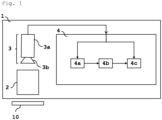
- Fig. 1 illustrates a configuration of the polarization evaluation device of the present invention.
- the polarization evaluation device 1 includes an illumination unit 2 that irradiates an observation target 10 with illumination light for observation; an imaging unit 3 that acquires polarization images in a plurality of specific directions of the reflected light from the observation target 10; and an image processing unit 4 that outputs an image of a result of evaluating polarization characteristics of the observation target 10 from the polarization images in the plurality of directions acquired by the imaging unit 3.
- the image processing unit 4 includes a correction coefficient calculation unit 4a that generates a correction coefficient for removing a polarization noise based on polarization characteristics of the optical system excluding the observation target 10; a correction coefficient storage unit 4b that stores the correction coefficient; and a polarization characteristic evaluation unit 4c that creates corrected polarization images produced from the polarization images in the plurality of directions by removing the polarization noise on the basis of the correction coefficient, and then outputs a result of evaluating the polarization characteristics of the observation target 10 from the corrected polarization images created.
- a correction coefficient calculation unit 4a that generates a correction coefficient for removing a polarization noise based on polarization characteristics of the optical system excluding the observation target 10
- a correction coefficient storage unit 4b that stores the correction coefficient
- a polarization characteristic evaluation unit 4c that creates corrected polarization images produced from the polarization images in the plurality of directions by removing the polarization noise on the basis of the correction coefficient, and then outputs a result of
- any image sensor, camera lens, or other equipment may be used.
- any illumination may be used.
- the irradiation angle of the illumination light with respect to the observation target 10 and the light incident angle from an imaging surface to the image sensor may be arbitrarily set according to the evaluation target and the purpose of the evaluation, and the present invention is not limited by the configuration of the optical system.
- the imaging unit 3 preferably has a configuration capable of acquiring polarization images in three or more directions. Hereinafter, the reason for this will be described.
- Measurement of polarization characteristics requires polarization images in a plurality of specific directions.
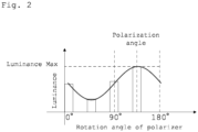
- the observation target 10 is irradiated with light from the illumination unit 2 and reflected light from the observation target 10 is imaged by the imaging unit 3 via a polarizer, the luminance of the captured image of the observation target 10 changes according to the relative phase between the polarization direction of the reflected light from the observation target 10 and the direction of the polarizer. This luminance change is indicated by a sine wave having a cycle of 180° as illustrated in Fig. 2 .
- the acquired polarization images in the three directions preferably include directions having a phase difference of 45° or more in order to maintain fitting accuracy.
- the imaging unit 3 preferably has a configuration capable of acquiring polarization images in three or more directions.
- the imaging unit 3 may be configured to use an image sensor in which blocks in which polarizers differing from each other in polarization direction are disposed in pixels are arranged in an array manner.
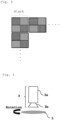
- Fig. 3 illustrates an example of an image sensor in which a plurality of blocks is arranged in an array manner, in which the blocks each include 2 ⁇ 2 pixels in which polarizers having polarization directions differing pixel by pixel (for example, four directions of 0°, 45°, 90°, and 135°) are disposed.
- imaging unit 3 may be an imaging unit 3 in which a rotatable polarizer 5 is disposed in front of a lens 3b and which is configured such that imaging is repeated with the polarizer 5 being rotated by a plurality of angles.
- Fig. 4 illustrates an example of the imaging unit 3 having a configuration in which the rotatable polarizer 5 is disposed in front of the lens 3b.
- any image sensor or configuration may be used as long as polarization images in three or more directions can be acquired.
- the light incident angle from an imaging surface of the imaging unit 3 to the image sensor may be arbitrarily arranged according to the evaluation target and the purpose of the evaluation.
- the captured polarization images in the plurality of directions are output to an image processing unit 4. These polarization images are output to a correction coefficient calculation unit 4a in the case of being used to create a correction coefficient, and are output to a polarization characteristic evaluation unit 4c in the case of being used to measure polarization characteristics, according to the purpose.
- the illumination unit 2 irradiates the observation target 10 with illumination light for observation.
- any illumination may be used because polarization characteristics derived from an optical system are acquired in advance (for example, acquired for each pixel), a correction coefficient for removing the polarization noise is created, and only the polarization characteristics derived from the observation target 10 can be evaluated.
- the irradiation angle of the illumination light with respect to the observation target 10 is not specified, and may be arbitrarily set and arranged according to the evaluation target and the evaluation contents.
- the illumination light is not particularly specified, and light having an arbitrary wavelength may be used.
- the image processing unit 4 includes a correction coefficient calculation unit 4a that generates a correction coefficient for removing a polarization noise based on polarization characteristics of the optical system excluding the observation target 10; a correction coefficient storage unit 4b that stores the correction coefficient; and a polarization characteristic evaluation unit 4c that creates corrected polarization images produced from the polarization images in the plurality of directions by removing the polarization noise on the basis of the correction coefficient, evaluates the polarization characteristics of the observation target from the corrected polarization images, and then outputs images.
- a correction coefficient calculation unit 4a that generates a correction coefficient for removing a polarization noise based on polarization characteristics of the optical system excluding the observation target 10
- a correction coefficient storage unit 4b that stores the correction coefficient
- a polarization characteristic evaluation unit 4c that creates corrected polarization images produced from the polarization images in the plurality of directions by removing the polarization noise on the basis of the correction coefficient, evaluates the polarization characteristics of the observation target from
- a polarization image is input from the imaging unit 3 to the image processing unit 4.
- This polarization image can be input to the correction coefficient calculation unit 4a in the case of being used for calculation of a correction coefficient for correcting a polarization noise of the optical system, and can be input to the polarization characteristic evaluation unit 4c in the case of being used for polarization characteristic evaluation of the observation target 10.
- Fig. 5 is a flowchart of the operation of the correction coefficient calculation unit 4a.
- Polarization images in a plurality of specific directions captured as correction images as described later are input to the correction coefficient calculation unit 4a.
- the correction coefficient calculation unit 4a calculates polarization characteristics (polarization angle and degree of polarization) of the observation target 10 from the input polarization images in the plurality of specific directions, for example, pixel by pixel and block by block. Then, a correction coefficient is calculated pixel by pixel and block by block from the calculated polarization characteristics, and the calculated correction coefficients are output to the correction coefficient storage unit 4b.
- polarization characteristics polarization angle and degree of polarization
- the calculation of the correction coefficient may be performed once for each configuration of the optical system, and the information of the calculated correction coefficient can be repeatedly used for the subsequent polarization characteristic evaluation by storing the information in the correction coefficient storage unit 4b.
- the correction image is an image obtained by imaging the correction observation target.
- the correction observation target may be any target in which the polarization direction among the polarization characteristics of the optical system and the proportion (polarization) of the polarization component of the light incident on the imaging sensor can be clarified.
- an object that is obvious to return polarized light when reflecting the observation illumination light can be used as a correction observation target.
- a plurality of polarization images obtained by imaging the correction observation target while rotating the correction observation target by a constant rotation angle may be used.
- correction polarization images polarization images in a plurality of specific directions captured by imaging an unpolarized target are used. For example, it is preferable to use an image obtained by imaging a target exhibiting uniform polarization characteristics regardless of a place, such as copy paper or a resin plate surface-treated so as to be unpolarized.
- the amount of illumination light at this time is denoted by 1.
- a sine wave that reproduces the relationship between the direction ⁇ of the polarization of the imaging unit 3 and the luminance I ⁇ is obtained pixel by pixel by performing fitting, and the angle at which the luminance takes the maximum value in the sine wave obtained by the fitting is calculated pixel by pixel as the polarization direction (polarization angle) of the reflected light from the observation target.
- the blocks each include a combination of a plurality of pixels in which polarizers differing pixel by pixel in polarization direction are disposed as illustrated in Fig.
- a polarization angle is calculated block by block from the fitting, and the results may be applied to each pixel in the blocks.
- the polarization angle may be calculated using (Equation 1) where the polarization angle is denoted by ⁇ and the luminance of each polarization image is denoted by I ⁇ .
- the polarization angle ⁇ and the degree of polarization k' of the polarization of the optical system are calculated for each pixel, and the correction information for correcting the polarization noise is calculated pixel by pixel and output to the correction information storage unit 4b.
- the optical system includes polarization characteristics
- the amount of light incident on the image sensor varies depending on the phase difference between the angular component and the polarizer of the imaging unit and the intensity of the polarization component.
- the correction coefficient is determined on the basis of the degree of polarization k' of the polarization of the optical system and the phase difference between the direction ⁇ i of the polarizer of the constituent imaging unit and the polarization angle ⁇ of the polarization of the optical system.
- the calculated pixel correction coefficient s is output to the correction information storage unit 4b.
- a target whose reflected light exhibits polarization is imaged as a correction polarization image.
- a target whose reflected light is obvious to exhibit polarization such as a resin plate with a surface hairline-processed.
- Polarization images in a plurality of specific directions are captured with the target disposed at a certain angle.
- the method of capturing the polarization images in the plurality of specific directions may be any method as long as the method can acquire polarization images in three or more directions.
- polarization images in a plurality of specific directions may be acquired by one imaging operation using an image sensor in which blocks in which polarizers differing from each other in polarization direction are disposed in pixels are arranged in an array manner.
- imaging may be repeated with the polarizer 5 being rotated by a plurality of angles.
- a polarization angle ⁇ is calculated from the calculation formula of (Equation 1).
- the target is rotated, polarization images in a plurality of specific directions are similarly captured, and a polarization angle is calculated.
- the rotation angle of the target at this time is denoted by ⁇ . This operation is repeatedly performed with the target being rotated by a plurality of angles, and the results of polarization angle calculation at every rotation angles of the object are acquired.
- the luminance I ⁇ of the polarization image for each polarization direction ⁇ of each imaging unit involves the polarization of the observation target and the polarization of the optical system
- the luminance I ⁇ ' of the polarized light of the reflected light of the observation target is determined by (Equation 8).
- k and ⁇ are variables representing the degree of polarization and the polarization angle of the optical system, respectively.
- I ⁇ ′ I ⁇ 1 + k cos ⁇ i ⁇ ⁇ 1 + k
- the polarization angle ⁇ ' is recalculated from the calculation of (Equation 1) for each rotation angle of the target.
- the variables k and ⁇ representing the degree of polarization and the polarization angle of the polarization of the optical system are determined by performing least square approximation of the difference between the rotation angle ⁇ of the target and the recalculated polarization angle ⁇ '.
- a correction coefficient for correcting the polarization noise is calculated pixel by pixel according to (Equation 7) and output to the correction information storage unit 4b.
- the correction coefficient storage unit 4b stores a correction coefficient of each pixel for removing the polarization characteristics of the optical system calculated in advance by the correction coefficient calculation unit 4a.
- the correction coefficient information stored in the correction coefficient storage unit 4b at the time of polarization characteristic evaluation is output to the polarization characteristic evaluation unit 4c.
- Fig. 6 illustrates a flowchart of the operation of the polarization characteristic evaluation unit 4c.
- Polarization images in a plurality of specific directions obtained from the imaging unit 3 of the optical system are input to the polarization characteristic evaluation unit 4c.
- the correction coefficient information of each pixel stored in the correction coefficient storage unit 4b is input.
- a corrected polarization image is created by multiplying the correction coefficients of the polarization direction and the pixel position of the corresponding imaging unit 3 obtained from the correction coefficient storage unit 4b by the luminance value of each pixel of the input polarization image.
- arbitrary polarization state information is calculated using the corrected polarization image, and the result is output.
- the calculation result may be output as an image so that the calculation result can be visually recognized.
- the polarization state information to be calculated may be any information as long as it can be calculated from a plurality of polarization images.
- the angle at which the luminance takes the maximum value in the sine wave obtained by fitting can be calculated as a polarization angle.
- the degree of polarization (the inclusion proportion of the polarization component) of the waveform obtained by fitting can also be calculated by the calculation shown in (Equation 2).
- the imaging unit 3 used was an image sensor in which blocks in which polarizers of 0°, 45°, 90°, and 135° were arranged in pixels, respectively, were arranged in an array manner.
- the illumination unit 2 used was coaxial epi-illumination with a half mirror.
- a resin plate (observation target 10) having a hairline surface and being to emit reflected light being to exhibit polarization was placed on a fine movement rotary stage 6, and imaging was performed with the resin plate being rotated from 0 to 180° in 10° increments.
- a polarization angle was measured using (Equation 1) for the captured images.
- Fig. 8 are shown the rotation angle of the fine movement rotary stage 6 before the correction of the error due to the polarization characteristics of the above-described optical system and the error with the measured polarization angle.
- a measurement error of an angle of ⁇ 5° at most occurred. This reveals that in the configuration of this optical system, there is a factor that lowers the measurement accuracy in the optical system itself.
- a conceivable factor is that light is polarized when passing through the half mirror of the illumination unit, so that the illumination light has polarization characteristics.
- a correction image was acquired using a resin plate whose surface had been matted so as to be unpolarized.
- a correction coefficient s was calculated pixel by pixel by the method shown in [First mode of correction coefficient creation] described above, and a correction coefficient distribution was created.
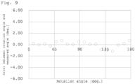
- Fig. 9 is shown the relationship between the rotation angle of the fine movement rotary stage after the correction of the error due to the polarization characteristics of the above-described optical system and the error with the measured polarization angle.
- the measurement error due to the polarization characteristics of illumination light can be reduced, the polarization state information to be originally measured can be more accurately measured, and the accuracy of polarization angle measurement can be improved by the technique of correcting the error due to the polarization characteristics of the optical system at the time of performing the polarization measurement.
- a resin plate (observation target 10) with a surface that had been hairline-processed so as reflected light exhibits polarization was placed on a fine movement rotary stage 6, and images were captured while the resin plate was rotated from 0 to 180° in 15° increments.
- a polarization angle was measured using (Equation 1) for the captured images.
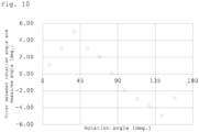
- Fig. 10 are shown the rotation angle of the fine movement rotary stage 6 before the correction of the error due to the polarization characteristics of the optical system and the error with the measured polarization angle.
- a correction coefficient s was calculated pixel by pixel by the method described in the [Second mode of correction coefficient creation] described above, and a correction coefficient distribution was created.
- the calculated correction coefficient corresponding to the polarization direction and the pixel position of the imaging unit is multiplied by the luminance value of each pixel of the polarization image obtained by imaging the observation target 10, and a corrected polarization image was thereby created.
- the polarization angle was measured again using (Equation 1).
- Fig. 11 is shown the relationship between the rotation angle of the fine movement rotary stage after the correction of the error due to the polarization characteristics of the optical system and the error with the measured polarization angle.
- the measurement error due to the polarization characteristics of illumination light can be reduced, the polarization state information to be originally measured can be more accurately measured, and the accuracy of polarization angle measurement can be improved by the technique of correcting the error due to the polarization characteristics of the optical system at the time of performing the polarization measurement.
- a correction coefficient is created from the polarization characteristics of an optical system acquired in advance, and then by use of the correction coefficient, polarization images obtained by imaging an observation target are subjected to correction processing of the polarization characteristics by the optical system. Therefore, it becomes possible to acquire a polarization image representing only the polarization characteristics of the observation target, and it becomes possible to evaluate the polarization characteristics of the observation target with high accuracy. Therefore, the present invention is particularly suitable for use in a device that performs, for example, highly accurate recognition of fiber orientation.
Landscapes
- Physics & Mathematics (AREA)
- General Physics & Mathematics (AREA)
- Health & Medical Sciences (AREA)
- Life Sciences & Earth Sciences (AREA)
- Chemical & Material Sciences (AREA)
- Analytical Chemistry (AREA)
- Biochemistry (AREA)
- General Health & Medical Sciences (AREA)
- Immunology (AREA)
- Pathology (AREA)
- Spectroscopy & Molecular Physics (AREA)
- Investigating Or Analysing Materials By Optical Means (AREA)
Abstract
there is provided a polarization evaluation device including:
an optical system including an illumination unit that irradiates an observation target with illumination light for observation, and an imaging unit that acquires polarization images in a plurality of specific directions from reflected light that is the illumination light reflected by the observation target; and
an image processing unit that outputs a result of evaluating polarization characteristic of the observation target from the polarization images in the plurality of specific directions acquired by the imaging unit,
in which
the image processing unit includes:
a correction coefficient calculation unit that generates a correction coefficient for removing a polarization noise based on polarization characteristics of the optical system excluding the observation target;
a correction coefficient storage unit that stores the correction coefficient; and
a polarization characteristic evaluation unit that performs processing that involves creating corrected polarization images produced from the polarization images in the plurality of specific directions by removing the polarization noise on the basis of the correction coefficient and outputting a result of evaluating the polarization characteristics of the observation target from the corrected polarization images.
Description
- The present invention relates to a technique for correcting an error due to the polarization characteristics of irradiation light when performing polarization distribution measurement of a target by polarized light observation.
- In recent years, polarization evaluation has been utilized as a technique for measuring fiber orientation for guaranteeing the stability of a nonwoven fabric sheet, a carbon fiber composite material, or the like, and as a technique for measuring strain of a film, glass, plastic, or the like. For example,
Patent Document 1 discloses a technique for measuring a fiber direction of a carbon fiber material of a test object using a polarization direction of light reflected by the test object by utilizing a fact that when unpolarized light strikes on a carbon fiber, light reflected by the fiber is polarized in a fiber direction. - Commonly, in polarized light observation, the polarization state information of an observation target is acquired by applying a model formula of polarization on the basis of the luminance information of polarization images in a plurality of directions obtained by imaging the observation target.
- Methods common as a method for capturing a polarization image are a method of forming polarization images in a plurality of directions by arranging a polarizer in front of an imaging unit and performing imaging while rotating the polarizer, and a method of acquiring polarization images in a plurality of directions at once using an image sensor in which blocks in which polarizers differing from each other in polarization direction are disposed in pixels are arranged in an array manner.
- Furthermore, a method of acquiring polarization state information of an observation target by applying a plurality of polarization images to a model formula of polarization has been disclosed. For example,
Patent Document 2 discloses an image processing device, an information acquisition device, and an information acquisition method for obtaining a high-quality polarization image. - Because the accuracy of measurement of polarization characteristics depends on the accuracy of polarization images in a plurality of directions, for example, variation in sensitivity among pixels of an image sensor becomes a problem in increasing accuracy of measurement. Therefore, for highly accurate measurement of polarization characteristics, it is necessary to acquire a high-quality polarization image or calibrate sensitivity variation. For example,
Patent Document 3 discloses a method for the calibration of a polarizer array for improving the accuracy of measurement of birefringence and polarization characteristics. Furthermore,Patent Document 4 discloses a light receiving device that has high sensitivity but can obtain highly accurate polarization state information even if the light receiving device includes a polarizing element in which absorption components frequently leak. -
- Patent Document 1:
Japanese Patent No. 6328130 - Patent Document 2:
Japanese Translation of PCT International Application Publication No. 2015-537211 - Patent Document 3:
Japanese Patent Laid-open Publication No. 2018-44865 - Patent Document 4:
Japanese Patent Laid-open Publication No. 2020-80366 - However, as in
Patent Document 3 andPatent Document 4, there is a case where the polarization of an observation target cannot be evaluated with sufficient accuracy only by correcting the sensitivity variation among pixels of an image sensor. In polarized light observation, illumination for observation is applied to an observation target and reflected light or transmitted light from the observation target is acquired by an image sensor. However, in the case, for example, where the illumination light to be applied latently has polarization characteristics, in addition to the polarization state information of the observation target, the polarization state information of the illumination light is also observed by the image sensor, so that the accuracy of evaluation of the polarization characteristics inherent in the observation target is deteriorated. - As described above, in addition to the variation in sensitivity among pixels derived from the image sensor, polarization may exist depending on the components of the optical system. Therefore, as described in
Patent Documents - In view of such background, an object of the present invention is to provide a polarization evaluation device for performing highly accurate polarization evaluation.
- The polarization evaluation device of the present invention that solves the above problems mainly has any of the following configurations.
- (1) A polarization evaluation device including:
- an optical system including an illumination unit that irradiates an observation target with illumination light for observation, and an imaging unit that acquires polarization images in a plurality of specific directions from reflected light that is the illumination light reflected by the observation target; and
- an image processing unit that outputs a result of evaluating polarization characteristic of the observation target from the polarization images in the plurality of specific directions acquired by the imaging unit,
- in which
- the image processing unit includes:
- a correction coefficient calculation unit that generates a correction coefficient for removing a polarization noise based on polarization characteristics of the optical system excluding the observation target;
- a correction coefficient storage unit that stores the correction coefficient; and
- a polarization characteristic evaluation unit that performs processing that involves creating corrected polarization images produced from the polarization images in the plurality of specific directions by removing the polarization noise on the basis of the correction coefficient and outputting a result of evaluating the polarization characteristics of the observation target from the corrected polarization images.
- (2) The polarization evaluation device according to (1), in which the polarization evaluation device calculates a polarization angle that is a polarization direction of polarization characteristics of the optical system and a degree of polarization that is an inclusion proportion of a polarization component from a correction image captured in advance, and calculates the correction coefficient from the polarization angle and the degree of polarization.
- (3) The polarization evaluation device according to (2), in which the correction image is a plurality of images captured with the observation target being rotated by a plurality of angles.
- (4) The polarization evaluation device according to (2), in which the correction image is an image captured by imaging a target having no polarization characteristics.
- (5) The polarization evaluation device according to any one of (1) to (4), in which the imaging unit images polarization components in three or more directions.
- (6) The polarization evaluation device according to any one of (1) to (5), in which the imaging unit is constituted of an image sensor which includes blocks which are each formed with a plurality of polarizers differing in polarization direction being disposed in respective corresponding pixels, and in which the blocks are arranged in an array manner.
- (7) The polarization evaluation device according to any one of (1) to (6), in which the correction coefficient is a coefficient calculated for each pixel constituting the imaging unit.
- (8) The polarization evaluation device according to any one of (1) to (7), in which the corrected polarization images are each an image calculated by multiplying a luminance value of each pixel of the polarization image acquired by the imaging unit by the correction coefficient.
- In accordance with the present invention, processing of correcting polarization characteristics of an optical system using correction information acquired in advance is performed on a polarization image. As a result, polarization characteristics can be evaluated with high accuracy because only the polarization characteristics of the observation target can be evaluated.
-
- [
Fig. 1] Fig. 1 is a diagram illustrating one example of a configuration of the polarization evaluation device of the present invention. - [
Fig. 2] Fig. 2 is a diagram illustrating one example of a relationship between luminance and a polarization angle. - [
Fig. 3] Fig. 3 is a diagram illustrating one example of an image sensor to be used for an imaging unit in the polarization evaluation device of the present invention. - [
Fig. 4] Fig. 4 is a diagram for explaining a configuration example of an imaging unit in the polarization evaluation device of the present invention. - [
Fig. 5] Fig. 5 is a flowchart illustrating an operation of a correction coefficient calculation unit. - [
Fig. 6] Fig. 6 is a flowchart illustrating an operation of a polarization characteristic evaluation unit. - [
Fig. 7] Fig. 7 is a diagram for explaining the configuration of the polarization evaluation device used in Example 1 and Example 2. - [
Fig. 8] Fig. 8 is a graph showing an error of the polarization angle measured without correcting an error due to the polarization characteristics of the optical system in Example 1. - [
Fig. 9] Fig. 9 is a graph showing an error of the polarization angle measured with correction of an error due to the polarization characteristics of the optical system in Example 1. - [
Fig. 10] Fig. 10 is a graph showing an error of the polarization angle measured without correcting an error due to the polarization characteristics of the optical system in Example 2. - [
Fig. 11] Fig. 11 is a graph showing an error of the polarization angle measured with correction of an error due to the polarization characteristics of the optical system in Example 2. -
Fig. 1 illustrates a configuration of the polarization evaluation device of the present invention. Thepolarization evaluation device 1 includes anillumination unit 2 that irradiates anobservation target 10 with illumination light for observation; animaging unit 3 that acquires polarization images in a plurality of specific directions of the reflected light from theobservation target 10; and animage processing unit 4 that outputs an image of a result of evaluating polarization characteristics of theobservation target 10 from the polarization images in the plurality of directions acquired by theimaging unit 3. Furthermore, theimage processing unit 4 includes a correctioncoefficient calculation unit 4a that generates a correction coefficient for removing a polarization noise based on polarization characteristics of the optical system excluding theobservation target 10; a correctioncoefficient storage unit 4b that stores the correction coefficient; and a polarizationcharacteristic evaluation unit 4c that creates corrected polarization images produced from the polarization images in the plurality of directions by removing the polarization noise on the basis of the correction coefficient, and then outputs a result of evaluating the polarization characteristics of theobservation target 10 from the corrected polarization images created. - As the
imaging unit 3 in thepolarization evaluation device 1, any image sensor, camera lens, or other equipment may be used. As theillumination unit 2 in thepolarization evaluation device 1, any illumination may be used. In addition, the irradiation angle of the illumination light with respect to theobservation target 10 and the light incident angle from an imaging surface to the image sensor may be arbitrarily set according to the evaluation target and the purpose of the evaluation, and the present invention is not limited by the configuration of the optical system. - The
imaging unit 3 preferably has a configuration capable of acquiring polarization images in three or more directions. Hereinafter, the reason for this will be described. - Measurement of polarization characteristics requires polarization images in a plurality of specific directions. When the
observation target 10 is irradiated with light from theillumination unit 2 and reflected light from theobservation target 10 is imaged by theimaging unit 3 via a polarizer, the luminance of the captured image of theobservation target 10 changes according to the relative phase between the polarization direction of the reflected light from theobservation target 10 and the direction of the polarizer. This luminance change is indicated by a sine wave having a cycle of 180° as illustrated inFig. 2 . Therefore, it is possible to obtain a sine wave that reproduces the relationship between the polarizer direction and the luminance of the polarization images in the plurality of specific directions by fitting with a formula of a sine wave having three variables of amplitude, phase, and offset, and then measure polarization characteristics, for example, by defining an angle at which the luminance takes a maximum value in the sine wave obtained by the fitting as the polarization direction (polarization angle) of the reflected light from the observation target. At this time, the acquired polarization images in the three directions preferably include directions having a phase difference of 45° or more in order to maintain fitting accuracy. - From the above, it can be said that the
imaging unit 3 preferably has a configuration capable of acquiring polarization images in three or more directions. - For example, the
imaging unit 3 may be configured to use an image sensor in which blocks in which polarizers differing from each other in polarization direction are disposed in pixels are arranged in an array manner.Fig. 3 illustrates an example of an image sensor in which a plurality of blocks is arranged in an array manner, in which the blocks each include 2 × 2 pixels in which polarizers having polarization directions differing pixel by pixel (for example, four directions of 0°, 45°, 90°, and 135°) are disposed. - Another example of the
imaging unit 3 may be animaging unit 3 in which arotatable polarizer 5 is disposed in front of alens 3b and which is configured such that imaging is repeated with thepolarizer 5 being rotated by a plurality of angles.Fig. 4 illustrates an example of theimaging unit 3 having a configuration in which therotatable polarizer 5 is disposed in front of thelens 3b. - In addition to the configuration illustrated as an example, any image sensor or configuration may be used as long as polarization images in three or more directions can be acquired.
- The light incident angle from an imaging surface of the
imaging unit 3 to the image sensor may be arbitrarily arranged according to the evaluation target and the purpose of the evaluation. - The captured polarization images in the plurality of directions are output to an
image processing unit 4. These polarization images are output to a correctioncoefficient calculation unit 4a in the case of being used to create a correction coefficient, and are output to a polarizationcharacteristic evaluation unit 4c in the case of being used to measure polarization characteristics, according to the purpose. - The
illumination unit 2 irradiates theobservation target 10 with illumination light for observation. In the present invention, any illumination may be used because polarization characteristics derived from an optical system are acquired in advance (for example, acquired for each pixel), a correction coefficient for removing the polarization noise is created, and only the polarization characteristics derived from theobservation target 10 can be evaluated. - The irradiation angle of the illumination light with respect to the
observation target 10 is not specified, and may be arbitrarily set and arranged according to the evaluation target and the evaluation contents. The illumination light is not particularly specified, and light having an arbitrary wavelength may be used. - The
image processing unit 4 includes a correctioncoefficient calculation unit 4a that generates a correction coefficient for removing a polarization noise based on polarization characteristics of the optical system excluding theobservation target 10; a correctioncoefficient storage unit 4b that stores the correction coefficient; and a polarizationcharacteristic evaluation unit 4c that creates corrected polarization images produced from the polarization images in the plurality of directions by removing the polarization noise on the basis of the correction coefficient, evaluates the polarization characteristics of the observation target from the corrected polarization images, and then outputs images. - A polarization image is input from the
imaging unit 3 to theimage processing unit 4. This polarization image can be input to the correctioncoefficient calculation unit 4a in the case of being used for calculation of a correction coefficient for correcting a polarization noise of the optical system, and can be input to the polarizationcharacteristic evaluation unit 4c in the case of being used for polarization characteristic evaluation of theobservation target 10. -
Fig. 5 is a flowchart of the operation of the correctioncoefficient calculation unit 4a. Polarization images in a plurality of specific directions captured as correction images as described later are input to the correctioncoefficient calculation unit 4a. The correctioncoefficient calculation unit 4a calculates polarization characteristics (polarization angle and degree of polarization) of theobservation target 10 from the input polarization images in the plurality of specific directions, for example, pixel by pixel and block by block. Then, a correction coefficient is calculated pixel by pixel and block by block from the calculated polarization characteristics, and the calculated correction coefficients are output to the correctioncoefficient storage unit 4b. Hereinafter, a case where a correction coefficient is calculated and used pixel by pixel will be described, but the same applies to a case where a correction coefficient is calculated and used block by block. - The calculation of the correction coefficient may be performed once for each configuration of the optical system, and the information of the calculated correction coefficient can be repeatedly used for the subsequent polarization characteristic evaluation by storing the information in the correction
coefficient storage unit 4b. - The correction image is an image obtained by imaging the correction observation target. The correction observation target may be any target in which the polarization direction among the polarization characteristics of the optical system and the proportion (polarization) of the polarization component of the light incident on the imaging sensor can be clarified. For example, it is preferable to use paper, a resin plate surface-treated so as to be unpolarized, or the like as a correction observation target. In addition, an object that is obvious to return polarized light when reflecting the observation illumination light can be used as a correction observation target. In this case, a plurality of polarization images obtained by imaging the correction observation target while rotating the correction observation target by a constant rotation angle may be used.
- Since the method of calculating the correction coefficient varies depending on the correction image to be acquired, the method of calculating the correction coefficient in each case will be described below.
- As the correction polarization images, polarization images in a plurality of specific directions captured by imaging an unpolarized target are used. For example, it is preferable to use an image obtained by imaging a target exhibiting uniform polarization characteristics regardless of a place, such as copy paper or a resin plate surface-treated so as to be unpolarized. The amount of illumination light at this time is denoted by 1.
- For the acquired polarization images in the plurality of specific directions, a sine wave that reproduces the relationship between the direction θ of the polarization of the
imaging unit 3 and the luminance Iθ is obtained pixel by pixel by performing fitting, and the angle at which the luminance takes the maximum value in the sine wave obtained by the fitting is calculated pixel by pixel as the polarization direction (polarization angle) of the reflected light from the observation target. In the case of using an image sensor in which a plurality of blocks is arranged in an array manner in which the blocks each include a combination of a plurality of pixels in which polarizers differing pixel by pixel in polarization direction are disposed as illustrated inFig. 3 , a polarization angle is calculated block by block from the fitting, and the results may be applied to each pixel in the blocks. In addition, in the case where polarization images in four directions of 0°, 45°, 90°, and 135° are used as correction images, the polarization angle may be calculated using (Equation 1) where the polarization angle is denoted by ϕ and the luminance of each polarization image is denoted by Iθ.
[Mathematical Formula 1]
- In addition, using the maximum value Imax and the minimum value Imin of the sine wave obtained by fitting, the intensity of the polarization component included in the reflected light is calculated as a degree of polarization k pixel by pixel by the calculation formula shown in (Equation 2).
[Mathematical Formula 2]
- In addition, using the maximum value Imax and the minimum value Imin of the sine wave obtained by fitting, the average luminance A of the reflected light is calculated pixel by pixel by the calculation formula shown in (Equation 3).
[Mathematical Formula 3]
- Next, similarly, polarization images in a plurality of specific directions are acquired for the observation target. The amount of the illumination light at the time of imaging at this time is denoted by l'. For the acquired polarization images in the plurality of specific directions, a sine wave that reproduces the relationship between the polarization direction and the luminance is obtained pixel by pixel by fitting. For the waveform obtained by the fitting, the average luminance A' of the reflected light is calculated pixel by pixel by the calculation formula of (Equation 4).
[Mathematical Formula 4]
- Subsequently, the average luminance A" of the reflected light from the observation target with the normalization of the amount l of the illumination light at the time of imaging the unpolarized target and the amount l' of the illumination light at the time of imaging the observation target is calculated by the calculation formula of (Equation 5).
[Mathematical Formula 5]
- In addition, the degree of polarization k' for each pixel of the polarization of the optical system included when the observation target is imaged is calculated by the calculation formula of (Equation 6).
[Mathematical Formula 6]
- As described above, the polarization angle ϕ and the degree of polarization k' of the polarization of the optical system are calculated for each pixel, and the correction information for correcting the polarization noise is calculated pixel by pixel and output to the correction
information storage unit 4b. - In the case where the optical system includes polarization characteristics, if the optical system has polarization in a specific direction, the amount of light incident on the image sensor varies depending on the phase difference between the angular component and the polarizer of the imaging unit and the intensity of the polarization component. The correction coefficient is determined on the basis of the degree of polarization k' of the polarization of the optical system and the phase difference between the direction θi of the polarizer of the constituent imaging unit and the polarization angle ϕ of the polarization of the optical system. The correction coefficient s is calculated for each pixel in accordance with (Equation 7).
[Mathematical Formula 7]
- The calculated pixel correction coefficient s is output to the correction
information storage unit 4b. - A target whose reflected light exhibits polarization is imaged as a correction polarization image. For example, it is preferable to image a target whose reflected light is obvious to exhibit polarization, such as a resin plate with a surface hairline-processed. Polarization images in a plurality of specific directions are captured with the target disposed at a certain angle. The method of capturing the polarization images in the plurality of specific directions may be any method as long as the method can acquire polarization images in three or more directions. For example, polarization images in a plurality of specific directions may be acquired by one imaging operation using an image sensor in which blocks in which polarizers differing from each other in polarization direction are disposed in pixels are arranged in an array manner. As another example, as illustrated in
Fig. 4 , using animaging unit 3 in which arotatable polarizer 5 is disposed in front of alens 3b, imaging may be repeated with thepolarizer 5 being rotated by a plurality of angles. Using the polarization images in the plurality of specific directions, a polarization angle ϕ is calculated from the calculation formula of (Equation 1). Next, the target is rotated, polarization images in a plurality of specific directions are similarly captured, and a polarization angle is calculated. The rotation angle of the target at this time is denoted by ρ. This operation is repeatedly performed with the target being rotated by a plurality of angles, and the results of polarization angle calculation at every rotation angles of the object are acquired. - Originally, the relationship between the rotation angle and the polarization angle of a target linearly changes, but in the case where the optical system has polarization characteristics, distortion occurs in the relationship.
- Since the luminance Iθ of the polarization image for each polarization direction θ of each imaging unit involves the polarization of the observation target and the polarization of the optical system, the luminance Iθ' of the polarized light of the reflected light of the observation target is determined by (Equation 8). k and ϕ are variables representing the degree of polarization and the polarization angle of the optical system, respectively.
[Mathematical formula 8]
- Using the luminance Iθ' of the polarized light of the observation target, the polarization angle ϕ' is recalculated from the calculation of (Equation 1) for each rotation angle of the target. The variables k and ϕ representing the degree of polarization and the polarization angle of the polarization of the optical system are determined by performing least square approximation of the difference between the rotation angle ρ of the target and the recalculated polarization angle ϕ'.
- From the polarization angle ϕ of each pixel and the degree of polarization k of each pixel of the polarization of the optical system, a correction coefficient for correcting the polarization noise is calculated pixel by pixel according to (Equation 7) and output to the correction
information storage unit 4b. - The variables in (Equation 1) to (Equation 8) are summarized as follows.
- ϕ Polarization angle
- θ Direction of polarization of imaging unit
- Iθ Luminance of image acquired by imaging unit
- Iθ' Luminance of polarized light in reflected light of observation target
- Imax Maximum value of sine wave obtained by fitting
- Imin Minimum value of sine wave obtained by fitting
- k Degree of polarization
- k' Degree of polarization of the polarization of optical system included when observation target is imaged
- l Amount of illumination light when imaging unpolarized target
- l' Amount of illumination light when imaging observation target
- A Average luminance of reflected light from unpolarized target
- A' Average luminance of reflected light from observation target
- A" Average luminance of reflected light from observation target with normalization of the amount of illumination light
- S Correction coefficient
- The correction
coefficient storage unit 4b stores a correction coefficient of each pixel for removing the polarization characteristics of the optical system calculated in advance by the correctioncoefficient calculation unit 4a. The correction coefficient information stored in the correctioncoefficient storage unit 4b at the time of polarization characteristic evaluation is output to the polarizationcharacteristic evaluation unit 4c. -
Fig. 6 illustrates a flowchart of the operation of the polarizationcharacteristic evaluation unit 4c. Polarization images in a plurality of specific directions obtained from theimaging unit 3 of the optical system are input to the polarizationcharacteristic evaluation unit 4c. Furthermore, the correction coefficient information of each pixel stored in the correctioncoefficient storage unit 4b is input. A corrected polarization image is created by multiplying the correction coefficients of the polarization direction and the pixel position of thecorresponding imaging unit 3 obtained from the correctioncoefficient storage unit 4b by the luminance value of each pixel of the input polarization image. - In addition, arbitrary polarization state information is calculated using the corrected polarization image, and the result is output. The calculation result may be output as an image so that the calculation result can be visually recognized. The polarization state information to be calculated may be any information as long as it can be calculated from a plurality of polarization images. For example, the angle at which the luminance takes the maximum value in the sine wave obtained by fitting can be calculated as a polarization angle. In addition, the degree of polarization (the inclusion proportion of the polarization component) of the waveform obtained by fitting can also be calculated by the calculation shown in (Equation 2).
- The following is description on examples carried out for evidencing the effect of a technique of correcting an error due to polarization characteristics of an optical system when measuring polarization using a device according to one embodiment of the present invention. It is noted that the present invention is not limited to the following examples.
- A technique for correcting an error due to the polarization characteristics of an optical system was performed using the optical system illustrated in
Fig. 7 . - The
imaging unit 3 used was an image sensor in which blocks in which polarizers of 0°, 45°, 90°, and 135° were arranged in pixels, respectively, were arranged in an array manner. Theillumination unit 2 used was coaxial epi-illumination with a half mirror. - A resin plate (observation target 10) having a hairline surface and being to emit reflected light being to exhibit polarization was placed on a fine movement
rotary stage 6, and imaging was performed with the resin plate being rotated from 0 to 180° in 10° increments. - A polarization angle was measured using (Equation 1) for the captured images. In
Fig. 8 are shown the rotation angle of the fine movementrotary stage 6 before the correction of the error due to the polarization characteristics of the above-described optical system and the error with the measured polarization angle. As shown inFig. 8 , in the case of measurement without correction, a measurement error of an angle of ±5° at most occurred.
This reveals that in the configuration of this optical system, there is a factor that lowers the measurement accuracy in the optical system itself. A conceivable factor is that light is polarized when passing through the half mirror of the illumination unit, so that the illumination light has polarization characteristics. - Next, in order to correct an error due to the polarization characteristics of the above-described optical system, a correction image was acquired using a resin plate whose surface had been matted so as to be unpolarized. Using the acquired correction image, a correction coefficient s was calculated pixel by pixel by the method shown in [First mode of correction coefficient creation] described above, and a correction coefficient distribution was created.
- Then, the calculated correction coefficient corresponding to the polarization direction and the pixel position of the imaging unit is multiplied by the luminance value of each pixel of the polarization image obtained by imaging the
observation target 10, and a corrected polarization image was thereby created. For this corrected polarization image, the polarization angle was measured again using (Equation 1). InFig. 9 is shown the relationship between the rotation angle of the fine movement rotary stage after the correction of the error due to the polarization characteristics of the above-described optical system and the error with the measured polarization angle. Although in the case of measurement without correction, a measurement error of an angle of ±5° at most occurred (seeFig. 8 ), it can be seen that the measurement error has well been reduced to a measurement error of an angle of ±1° at most as shown inFig. 9 . - From the results of the examples described above, it has been confirmed that according to the present embodiment, the measurement error due to the polarization characteristics of illumination light can be reduced, the polarization state information to be originally measured can be more accurately measured, and the accuracy of polarization angle measurement can be improved by the technique of correcting the error due to the polarization characteristics of the optical system at the time of performing the polarization measurement.
- Using the optical system illustrated in
Fig. 7 similarly to Example 1, a resin plate (observation target 10) with a surface that had been hairline-processed so as reflected light exhibits polarization was placed on a fine movementrotary stage 6, and images were captured while the resin plate was rotated from 0 to 180° in 15° increments. - A polarization angle was measured using (Equation 1) for the captured images. In
Fig. 10 are shown the rotation angle of the fine movementrotary stage 6 before the correction of the error due to the polarization characteristics of the optical system and the error with the measured polarization angle. As shown inFig. 10 , in the case of measurement without correction, a measurement error of an angle of ±5° at most occurred. - Next, in order to correct an error due to the polarization characteristics of the optical system described above, using a plurality of images of the resin plate captured with the resin plate being rotated from 0 to 180° in 15° increments on a fine movement
rotary stage 6 as correction images, a correction coefficient s was calculated pixel by pixel by the method described in the [Second mode of correction coefficient creation] described above, and a correction coefficient distribution was created. - Then, the calculated correction coefficient corresponding to the polarization direction and the pixel position of the imaging unit is multiplied by the luminance value of each pixel of the polarization image obtained by imaging the
observation target 10, and a corrected polarization image was thereby created. For this corrected polarization image, the polarization angle was measured again using (Equation 1). InFig. 11 is shown the relationship between the rotation angle of the fine movement rotary stage after the correction of the error due to the polarization characteristics of the optical system and the error with the measured polarization angle. Although in the case of measurement without correction, a measurement error of an angle of ±5° at most occurred (seeFig. 10 ), it can be seen that the measurement error has well been reduced to a measurement error of an angle of ±1.2° at most as shown inFig. 11 . - From the results of the examples described above, it has been confirmed that according to the present embodiment, the measurement error due to the polarization characteristics of illumination light can be reduced, the polarization state information to be originally measured can be more accurately measured, and the accuracy of polarization angle measurement can be improved by the technique of correcting the error due to the polarization characteristics of the optical system at the time of performing the polarization measurement.
- With the polarization evaluation device of the present invention, a correction coefficient is created from the polarization characteristics of an optical system acquired in advance, and then by use of the correction coefficient, polarization images obtained by imaging an observation target are subjected to correction processing of the polarization characteristics by the optical system. Therefore, it becomes possible to acquire a polarization image representing only the polarization characteristics of the observation target, and it becomes possible to evaluate the polarization characteristics of the observation target with high accuracy. Therefore, the present invention is particularly suitable for use in a device that performs, for example, highly accurate recognition of fiber orientation.
-
- 1: Polarization evaluation device
- 2: Illumination
- 3: Imaging unit
- 3a: Camera
- 3b: Lens
- 4: Image processing unit
- 4a: Correction coefficient calculation unit
- 4b: Correction coefficient storage unit
- 4c: Polarization characteristic evaluation unit
- 5: Polarizer
- 6: Fine movement rotary stage
- 10: Observation target
Claims (1)
- A polarization evaluation device comprising:an optical system including an illumination unit that irradiates an observation target with illumination light for observation, and an imaging unit that acquires polarization images in a plurality of specific directions from reflected light that is the illumination light reflected by the observation target; andan image processing unit that outputs a result of evaluating polarization characteristic of the observation target from the polarization images in the plurality of specific directions acquired by the imaging unit,whereinthe image processing unit includes:a correction coefficient calculation unit that generates a correction coefficient for removing a polarization noise based on polarization characteristics of the optical system excluding the observation target;a correction coefficient storage unit that stores the correction coefficient; anda polarization characteristic evaluation unit that performs processing that involves creating corrected polarization images produced from the polarization images in the plurality of specific directions by removing the polarization noise on the basis of the correction coefficient and outputting a result of evaluating the polarization characteristics of the observation target from the corrected polarization images.2. The polarization evaluation device according to claim 1, wherein the polarization evaluation device calculates a polarization angle that is a polarization direction of polarization characteristics of the optical system and a degree of polarization that is an inclusion proportion of a polarization component from a correction image captured in advance, and calculates the correction coefficient from the polarization angle and the degree of polarization.3. The polarization evaluation device according to claim 2, wherein the correction image is a plurality of images captured with the observation target being rotated by a plurality of angles.4. The polarization evaluation device according to claim 2, wherein the correction image is an image captured by imaging a target having no polarization characteristics.5. The polarization evaluation device according to any one of claims 1 to 4, wherein the imaging unit images polarization components in three or more directions.6. The polarization evaluation device according to any one of claims 1 to 5, wherein the imaging unit is constituted of an image sensor which includes blocks which are each formed with a plurality of polarizers differing in polarization direction being disposed in respective corresponding pixels, and in which the blocks are arranged in an array manner.7. The polarization evaluation device according to any one of claims 1 to 6, wherein the correction coefficient is a coefficient calculated for each pixel constituting the imaging unit.8. The polarization evaluation device according to any one of claims 1 to 7, wherein the corrected polarization images are each an image calculated by multiplying a luminance value of each pixel of the polarization image acquired by the imaging unit by the correction coefficient.
Applications Claiming Priority (2)
| Application Number | Priority Date | Filing Date | Title |
|---|---|---|---|
| JP2022034965 | 2022-03-08 | ||
| PCT/JP2022/044844 WO2023171058A1 (en) | 2022-03-08 | 2022-12-06 | Polarization evaluation device |
Publications (2)
| Publication Number | Publication Date |
|---|---|
| EP4492020A1 true EP4492020A1 (en) | 2025-01-15 |
| EP4492020A4 EP4492020A4 (en) | 2026-02-25 |
Family
ID=87936499
Family Applications (1)
| Application Number | Title | Priority Date | Filing Date |
|---|---|---|---|
| EP22931029.7A Pending EP4492020A4 (en) | 2022-03-08 | 2022-12-06 | DEVICE FOR POLARIZATION ASSESSMENT |
Country Status (3)
| Country | Link |
|---|---|
| EP (1) | EP4492020A4 (en) |
| JP (1) | JPWO2023171058A1 (en) |
| WO (1) | WO2023171058A1 (en) |
Families Citing this family (2)
| Publication number | Priority date | Publication date | Assignee | Title |
|---|---|---|---|---|
| FR3128022B1 (en) * | 2021-10-08 | 2023-10-06 | Tiama | Device and opto-computing method for analyzing light passing through a glass container using a polarimetric digital camera |
| WO2025079431A1 (en) * | 2023-10-13 | 2025-04-17 | ソニーグループ株式会社 | Image processing device |
Family Cites Families (8)
| Publication number | Priority date | Publication date | Assignee | Title |
|---|---|---|---|---|
| JP4260683B2 (en) * | 2004-05-25 | 2009-04-30 | 大日本スクリーン製造株式会社 | Ellipsometer, polarization state acquisition method and light intensity acquisition method |
| DE102012220923B4 (en) * | 2012-11-15 | 2014-07-10 | Fraunhofer-Gesellschaft zur Förderung der angewandten Forschung e.V. | Measurement of a fiber orientation of a carbon fiber material and production of a component in carbon fiber composite construction |
| WO2017099253A1 (en) * | 2015-12-11 | 2017-06-15 | 株式会社ニコン | Polarization property image measurement device and polarization property image measurement method |
| JP2018044865A (en) | 2016-09-14 | 2018-03-22 | 国立大学法人宇都宮大学 | Method of calibrating optical device |
| EP3580546A1 (en) * | 2017-02-08 | 2019-12-18 | Yissum Research Development Company of The Hebrew University of Jerusalem Ltd. | System and method for use in high spatial resolution ellipsometry |
| US11637967B2 (en) * | 2018-04-09 | 2023-04-25 | Sony Corporation | Information processing apparatus, information processing method, and calibration apparatus |
| JP2020080366A (en) | 2018-11-13 | 2020-05-28 | ソニーセミコンダクタソリューションズ株式会社 | Light receiving device |
| CN112417370B (en) * | 2020-11-12 | 2024-04-30 | 南京航空航天大学 | Mueller-Jones matrix estimation and polarization noise analysis method for rough surface materials |
-
2022
- 2022-12-06 EP EP22931029.7A patent/EP4492020A4/en active Pending
- 2022-12-06 WO PCT/JP2022/044844 patent/WO2023171058A1/en not_active Ceased
- 2022-12-06 JP JP2022575756A patent/JPWO2023171058A1/ja active Pending
Also Published As
| Publication number | Publication date |
|---|---|
| WO2023171058A1 (en) | 2023-09-14 |
| JPWO2023171058A1 (en) | 2023-09-14 |
| EP4492020A4 (en) | 2026-02-25 |
Similar Documents
| Publication | Publication Date | Title |
|---|---|---|
| KR20190096831A (en) | Polarization Measuring Device, Polarization Measuring Method and Optical Alignment Method | |
| CN111443045B (en) | Spectral imaging analysis system and spectral imaging analysis method | |
| US20040257565A1 (en) | Polarization bearing detection type two-dimensional light reception timing detecting device and surface shape measuring device using it | |
| EP2827097A1 (en) | Phase distribution analysis method and device for fringe image using high-dimensional brightness information, and program therefor | |
| US20040156051A1 (en) | Method and apparatus for measuring birefringence | |
| US6693710B1 (en) | Polarization imaging system | |
| CN102095387A (en) | Optical rotation angle field detection device based on polarized beam splitting imaging and measurement method thereof | |
| KR20170039232A (en) | Birefringence measurement device and birefringence measurement method | |
| WO2023171058A1 (en) | Polarization evaluation device | |
| Huang et al. | Hybrid calibration method for Mueller matrix microscopy | |
| JP2010071878A (en) | Sensitivity adjustment method, polarization measurement method, and polarization measuring instrument | |
| CN109120920A (en) | A kind of correction system of the polarization camera based on pixel delineation | |
| CN103210294A (en) | Optical characteristic measuring device and method | |
| JP2011075548A (en) | Fourier coefficient measuring method using integration type photodetector | |
| KR101373709B1 (en) | The measurement device and the method of the principle axis and retardation of the 3-dimensional film | |
| JP2006023295A (en) | Birefringence measuring method and birefringence measuring apparatus using the same | |
| JP2018044865A (en) | Method of calibrating optical device | |
| CN102566095B (en) | Method and system for measuring gamma curves of liquid crystal spatial light modulator | |
| CN112880987A (en) | Polarization performance detection method and system of optical element | |
| CN105136295A (en) | Solution method and apparatus for spectrum non-uniformity in same image of AOTF | |
| JP2000111472A (en) | Birefringence measuring device and film orientation measuring device | |
| JP2010139345A (en) | Birefringence measurement apparatus | |
| JPH11142322A (en) | Birefringence measuring device and birefringence measuring method | |
| JP3436704B2 (en) | Birefringence measuring method and apparatus therefor | |
| CN120628294A (en) | Visible light wide-band polarization imaging system and imaging method based on liquid crystal variable phase retarder |
Legal Events
| Date | Code | Title | Description |
|---|---|---|---|
| STAA | Information on the status of an ep patent application or granted ep patent |
Free format text: STATUS: THE INTERNATIONAL PUBLICATION HAS BEEN MADE |
|
| PUAI | Public reference made under article 153(3) epc to a published international application that has entered the european phase |
Free format text: ORIGINAL CODE: 0009012 |
|
| STAA | Information on the status of an ep patent application or granted ep patent |
Free format text: STATUS: REQUEST FOR EXAMINATION WAS MADE |
|
| 17P | Request for examination filed |
Effective date: 20240625 |
|
| AK | Designated contracting states |
Kind code of ref document: A1 Designated state(s): AL AT BE BG CH CY CZ DE DK EE ES FI FR GB GR HR HU IE IS IT LI LT LU LV MC ME MK MT NL NO PL PT RO RS SE SI SK SM TR |
|
| DAV | Request for validation of the european patent (deleted) | ||
| DAX | Request for extension of the european patent (deleted) | ||
| A4 | Supplementary search report drawn up and despatched |
Effective date: 20260126 |
|
| RIC1 | Information provided on ipc code assigned before grant |
Ipc: G01J 4/04 20060101AFI20260120BHEP Ipc: G01N 21/21 20060101ALI20260120BHEP |