EP4491906A1 - A pulley arrangement for a belt drive and agricultural machine with such - Google Patents
A pulley arrangement for a belt drive and agricultural machine with such Download PDFInfo
- Publication number
- EP4491906A1 EP4491906A1 EP23185394.6A EP23185394A EP4491906A1 EP 4491906 A1 EP4491906 A1 EP 4491906A1 EP 23185394 A EP23185394 A EP 23185394A EP 4491906 A1 EP4491906 A1 EP 4491906A1
- Authority
- EP
- European Patent Office
- Prior art keywords
- pulley
- ring disc
- belt drive
- input shaft
- arrangement
- Prior art date
- Legal status (The legal status is an assumption and is not a legal conclusion. Google has not performed a legal analysis and makes no representation as to the accuracy of the status listed.)
- Pending
Links
Images




Classifications
-
- F—MECHANICAL ENGINEERING; LIGHTING; HEATING; WEAPONS; BLASTING
- F16—ENGINEERING ELEMENTS AND UNITS; GENERAL MEASURES FOR PRODUCING AND MAINTAINING EFFECTIVE FUNCTIONING OF MACHINES OR INSTALLATIONS; THERMAL INSULATION IN GENERAL
- F16H—GEARING
- F16H7/00—Gearings for conveying rotary motion by endless flexible members
- F16H7/02—Gearings for conveying rotary motion by endless flexible members with belts; with V-belts
-
- F—MECHANICAL ENGINEERING; LIGHTING; HEATING; WEAPONS; BLASTING
- F16—ENGINEERING ELEMENTS AND UNITS; GENERAL MEASURES FOR PRODUCING AND MAINTAINING EFFECTIVE FUNCTIONING OF MACHINES OR INSTALLATIONS; THERMAL INSULATION IN GENERAL
- F16H—GEARING
- F16H57/00—General details of gearing
- F16H57/04—Features relating to lubrication or cooling or heating
- F16H57/0412—Cooling or heating; Control of temperature
- F16H57/0415—Air cooling or ventilation; Heat exchangers; Thermal insulations
- F16H57/0416—Air cooling or ventilation
-
- A—HUMAN NECESSITIES
- A01—AGRICULTURE; FORESTRY; ANIMAL HUSBANDRY; HUNTING; TRAPPING; FISHING
- A01D—HARVESTING; MOWING
- A01D69/00—Driving mechanisms or parts thereof for harvesters or mowers
- A01D69/06—Gearings
-
- F—MECHANICAL ENGINEERING; LIGHTING; HEATING; WEAPONS; BLASTING
- F16—ENGINEERING ELEMENTS AND UNITS; GENERAL MEASURES FOR PRODUCING AND MAINTAINING EFFECTIVE FUNCTIONING OF MACHINES OR INSTALLATIONS; THERMAL INSULATION IN GENERAL
- F16H—GEARING
- F16H55/00—Elements with teeth or friction surfaces for conveying motion; Worms, pulleys or sheaves for gearing mechanisms
- F16H55/02—Toothed members; Worms
- F16H55/17—Toothed wheels
- F16H55/171—Toothed belt pulleys
-
- F—MECHANICAL ENGINEERING; LIGHTING; HEATING; WEAPONS; BLASTING
- F16—ENGINEERING ELEMENTS AND UNITS; GENERAL MEASURES FOR PRODUCING AND MAINTAINING EFFECTIVE FUNCTIONING OF MACHINES OR INSTALLATIONS; THERMAL INSULATION IN GENERAL
- F16H—GEARING
- F16H55/00—Elements with teeth or friction surfaces for conveying motion; Worms, pulleys or sheaves for gearing mechanisms
- F16H55/32—Friction members
- F16H55/36—Pulleys
-
- F—MECHANICAL ENGINEERING; LIGHTING; HEATING; WEAPONS; BLASTING
- F16—ENGINEERING ELEMENTS AND UNITS; GENERAL MEASURES FOR PRODUCING AND MAINTAINING EFFECTIVE FUNCTIONING OF MACHINES OR INSTALLATIONS; THERMAL INSULATION IN GENERAL
- F16H—GEARING
- F16H7/00—Gearings for conveying rotary motion by endless flexible members
- F16H7/02—Gearings for conveying rotary motion by endless flexible members with belts; with V-belts
- F16H7/023—Gearings for conveying rotary motion by endless flexible members with belts; with V-belts with belts having a toothed contact surface or regularly spaced bosses or hollows for slipless or nearly slipless meshing with complementary profiled contact surface of a pulley
Definitions
- the invention relates to a pulley arrangement comprising an input shaft, a pulley and a protection device.
- the input shaft comprises a first end and a second end, wherein the first end of the input shaft is configured to be couplable to a gear box.
- the pulley having an inner pulley surface and an outer pulley surface, is mounted coaxially on the input shaft.
- the invention further relates to the pulley arrangement for a belt drive of an agricultural machine.
- Agricultural machines such as combine harvesters, balers are well known and are used for travel through fields for agricultural processes such as harvesting, collecting and bundling the crops etc.
- the debris such as chaff, stalks, cobs, etc. are for example the result of the chopping process within a harvesting machine or due to spreading of existing debris lying on field during the travel of agricultural machines in the field.
- This debris and dust usually accumulate on the components of the machine such as drives, gearboxes, pulleys etc. during its travel.
- the problem is compounded by accumulation of debris and plugging of the machine components. Often, this accumulation and plugging tend to create an issue around the mechanics.
- the agricultural machines must be stopped resulting in undesirable downtime.
- One example is the accumulation of the debris around pulley arrangement for a belt drive and its components. This leads to create friction between pulley, its components and/or housing of the pulley which in turn leads to wearing of the pulley arrangement and its components.
- the objective of the invention is to provide a pulley arrangement as described above which overcomes the above-mentioned problem.
- a pulley arrangement of above-mentioned type will be provided.
- the pulley arrangement further comprising a protection device having at least one ring disc fastened coaxially to the inner pulley surface or the outer pulley surface, wherein a plurality of air flow directing means extending from an inner diameter to an outer diameter of the ring disc, and wherein a circumferential ring disc gap is provided between the at least one ring disc and the input shaft.
- ring disc may fasten coaxially to the inner pulley surface or the outer pulley surface with the help of bolts, screws, rivets or any such similar fasteners or couplers.
- the ring disc and the pulley may be welded, casted or forged together.
- the at least one ring disc may comprise one ring disc fastened coaxially to the inner pulley surface and a circumferential pulley gap is provided between the pulley and the input shaft.
- the mentioned pulley gap may provide an air flow channel from the outer pulley surface towards the inner pulley surface to guide air to the ring disc fastened on the inner pulley surface.
- the at least one ring disc may comprise a first ring disc fastened coaxially to the outer pulley surface and a second ring disc fastened coaxially to the inner pulley surface and a circumferential pulley gap is provided between the pulley and the input shaft. Due to this alternative, the pulley is provided with a ring disc fastened on each of its sides. Providing a ring disc on both sides of the pulley will provide air flow to an area surrounding both pulley surfaces.
- the first ring disc, second ring disc and the pulley may be welded, casted or forged together.
- the ring discs may be disposed such that the plurality of air flow directing means of the respective ring disc is facing the respective pulley surface.
- the plurality of air flow directing means of ring discs may be available on both faces of the ring discs.
- a plurality of fastening provisions may be located circumferentially between the inner and the outer diameter of the ring disc.
- the fastening provisions may be for example holes of any suitable shapes such as for the above-mentioned bolts, screws, rivets or any such similar fasteners or couplers.
- the plurality of air flow directing means may extend in a curved shape towards an opposite direction of the rotation of the pulley.
- the air flow directing means may extend in radially linear shape towards the opposite direction of the rotation of the pulley.
- the shape of the air flow directing means may comprise a twisted shape such as propeller blades or ventilator blades or such similar profiles.
- the plurality of air flow directing means may extend in a curved shape towards direction of the rotation of the pulley.
- the air flow directing means may extend in radially linear shape towards the direction of the rotation of the pulley.
- the shape of the air flow directing means may comprise a twisted shape such as propeller blades or ventilator blades or such similar profiles.
- the air flow directing means might be protrusions or grooves formed on a surface between the inner and the outer diameter of the at least one ring disc.
- the air flow directing means may be also formed by fins or wings or blades.
- the air flow directing means may be welded or printed on the ring disc or the rind disc may be casted or forged together with the air flow directing means.
- a belt drive might be provided comprising a pulley arrangement as proposed above.
- an agricultural machine may comprise a belt drive as mentioned above.
- the agricultural machine may be a combine harvester, a forage harvester or a baler.
- an agricultural machine in form of a combine harvester 10 is shown as an example.
- the agricultural machine may be also a forage harvester or a baler.
- the combine harvester 10 includes a main frame 12 that provides a structure for mounting combine body 14 and supported above the ground on forward drive wheels 16 and rear wheels 18. Alternatively, the combine harvester 10 may be fully or partially supported on ground-engaging crawler tracks. Further, the combine harvester 10 includes an operator station 20 which houses a seat for an operator and several controls which may be manipulated by the operator in order to control operations of the combine harvester 10. In operation, a forward mounted header 22 cut a crop material from a field and converges it to a feeder house 24 for transferring it to process further inside the combine body 14.
- the cut crop material is threshed, separated, cleaned and disposed by a threshing and separating unit 26, a cleaning system 28 and residue disposal system 30 respectively.
- the threshing and separating unit 26, the cleaning system 28 and the residue disposal system 30 are suitably housed within the combine body 14.
- the mentioned various operations require power, which is provided by an engine 32 mounted on the main frame 12 and housed within the combine body 14.
- an electric drive may act as a prime mover and also fulfil the power requirement for various operations.
- the electric drive may be an auxiliary drive to assist the engine 32.
- a power transfer means 34 transfers power from engine to various components of the combine harvester 10 to perform these operations.
- the power transfer means 34 comprise a belt drive 36 which includes a pulley arrangement 38.
- power from engine 32 is provided to the residue disposal system 30 as shown in Fig. 1 .
- the pulley arrangement 38 for the belt drive 36.
- the pulley arrangement 38 comprises an input shaft 40.
- the input shaft 40 is having first end 42 and second end 44.
- the first end 42 of the input shaft 40 is configured to be couplable to a gear box 46.
- the pulley arrangement 38 comprises a pulley 48.
- the pulley 48 is having an inner pulley surface 50 and an outer pulley surface 52.
- the pulley 48 is mounted coaxially on the input shaft 40.
- the pulley 48 may be manufactured with extensive variety of materials such as aluminum, brass, cast iron, plastic, stainless steel, steel, and zinc alloy etc. to ensure greater stability.
- the pulley arrangement 38 comprises a protection device 54 in form of a ring disc 56.
- the ring disc 56 is fastened coaxially to the outer pulley surface 52.
- the ring disc 56 is fastened coaxially to the outer pulley surface 52 with the help of screws 58.
- a circumferential ring disc gap 60 is provided between the at least one ring disc 56 and the input shaft 40.
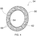
- a plurality of fastening provisions 62 are located circumferentially between the inner 64 and the outer diameter 66 of the ring disc 56.
- the fastening provisions 62 are made of holes for receiving the above-mentioned screws 58.
- a plurality of air flow directing means 68 is extending from an inner diameter 64 to an outer diameter 66 of the ring disc 56.
- the plurality of air flow directing means 68 extends in a curved shape from an inner diameter 64 to an outer diameter 66 of the ring disc 56.
- the direction of the curves of the flow directing means 68 can be both, towards or against direction of rotation of the pulley 48. In both cases, circulation of air, respectively an air curtain is created, when the ring disc 56 is rotating, as described in more detail below. With that an accumulation of debris or dust is restrained from plugging on the pulley surfaces 50, 52.
- the air flow directing means 68 are protrusions formed on a surface between the inner diameter 64 and the outer diameter 66 of the ring disc 56.
- the air flow directing means 68 may be grooves formed on the on a surface between the inner diameter 64 and the outer diameter 66 of the ring disc 56.
- the belt drive 36 drives the pulley 48 which in turn rotate the ring disc 56 fastened to the pulley 48. This creates a pressure difference to draw air axially inwards through circumferential ring disc gap 60 and pushes it radially outwards through the air flow directing means 68 to generate a curtain of air at outer pulley surface 52.
- the curtain of air restrains accumulation or entry of debris into the pulley 48 or into components of the agricultural machine 10.
- Fig. 5 shows an embodiment having pulley arrangement 70.
- the ring disc 56 is fastened coaxially to the inner pulley surface 50.
- one or more of a circumferential pulley gap 72 is provided between the pulley 48 and the input shaft 40.
- a shim 74 is fastened at the outer pulley surface 52.
- the shim 74 is designed to provide one or more shim gaps 76 between the shim 74 and the input shaft 40. Said one or more gaps can be for example a circumferential gap 76 between inner diameter of the shim 74 and outer diameter of the input shaft 40.
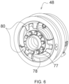
- said gaps can be provided by recesses or cut outs 77 (as indicated in Fig. 5 and Fig. 6 as an additional example) along the thickness of an inner circumferential edge of the shim 74 in addition or instead of the circumferential gap 76.
- similar recesses or cut outs (not shown) along the thickness of an inner circumferential edge of the pulley 48 can be provided instead or in addition to the circumferential pulley gap 72. Said similar recesses or cut-outs are aligned to the recesses or cut outs 77 of the shim 74.
- This shim gap 76 along with the circumferential pulley gap 72, respectively said alternative recesses or cut outs on the shim 74 and the pulley 48, create an axial channel for air to be drawn inwards (towards the inner pulley surface 50) in case of suction and air is pushed radially outwards through the air flow directing means 68 to generate said curtain of air.
- This curtain of air is generated at outer pulley surface 52 as the radially pushed air flows from the inner pulley surface 50 to the outer pulley surface 52 through openings 78 provided between spokes 80 of the pulley 48 as shown in Fig. 6 .
- the curtain of air as described restrains accumulation or entry of debris from outer pulley surface 52 into the pulley 48 or into components of the agricultural machine 10. Additionally, a portion of the air curtain is formed at the inner pulley surface 50 too which restrains accumulation or entry of debris into the pulley 48 or into components of the agricultural machine 10 at inner side of the pulley 48.
- Fig. 7 shows an embodiment having pulley arrangement 82.
- a first ring disc 84 fastened coaxially to the outer pulley surface 52 and a second ring disc 86 fastened coaxially to the inner pulley surface 50.
- the circumferential pulley gap 72 is provided between the pulley 48 and the input shaft 40.
- the recesses or cut outs can be provided.
- the first ring disc 84 is designed in a way to provide the circumferential ring disc gap 60 between the first ring disc 84 and the input shaft 40.
- the recesses or cut outs can be provided.
- the circumferential ring disc gap 60 along with the circumferential pulley gap 72, respectively said alternative recesses or cut outs on the first ring disc 84 and on the pulley 48, create an axial channel for air to be drawn inwards (towards the inner pulley surface 50) due to suction and air is pushed radially outwards through the air flow directing means 68 to generate said curtain of air.
- the ring discs 84, 86 are disposed such that the plurality of air flow directing means 68 of the respective ring disc 84, 86 is facing the respective pulley surface 50, 52.
- the effects of creating air flow, respectively providing a curtain of air, having the ring disc on the outer pulley surface and on the inner pulley surface are combined.
Landscapes
- Engineering & Computer Science (AREA)
- General Engineering & Computer Science (AREA)
- Mechanical Engineering (AREA)
- Life Sciences & Earth Sciences (AREA)
- Environmental Sciences (AREA)
- Pulleys (AREA)
Abstract
Description
- The invention relates to a pulley arrangement comprising an input shaft, a pulley and a protection device. The input shaft comprises a first end and a second end, wherein the first end of the input shaft is configured to be couplable to a gear box. The pulley having an inner pulley surface and an outer pulley surface, is mounted coaxially on the input shaft.
- The invention further relates to the pulley arrangement for a belt drive of an agricultural machine.
- Agricultural machines, such as combine harvesters, balers are well known and are used for travel through fields for agricultural processes such as harvesting, collecting and bundling the crops etc. During and/or after the agricultural processes, a lot of debris and dust are produced by the agricultural machines. The debris such as chaff, stalks, cobs, etc. are for example the result of the chopping process within a harvesting machine or due to spreading of existing debris lying on field during the travel of agricultural machines in the field. This debris and dust usually accumulate on the components of the machine such as drives, gearboxes, pulleys etc. during its travel. The problem is compounded by accumulation of debris and plugging of the machine components. Often, this accumulation and plugging tend to create an issue around the mechanics. Once plugged, the agricultural machines must be stopped resulting in undesirable downtime. One example is the accumulation of the debris around pulley arrangement for a belt drive and its components. This leads to create friction between pulley, its components and/or housing of the pulley which in turn leads to wearing of the pulley arrangement and its components.
- Further, it impacts the lubrication connections to the pulley arrangements. Particularly, friction created by accumulation of debris may create overheating and harming the belt and/or other components connected with the pulley arrangement of the machine.
- As a result of the above, it would be advantageous to provide means to reduce or to avoid such debris accumulation on the pulley arrangement. In other words, such belt driven pulleys may need to be cleaned or protected for proper working of components as described above.
- Therefore, the objective of the invention is to provide a pulley arrangement as described above which overcomes the above-mentioned problem.
- The object will be achieved by the teaching of the claim 1, wherein further advantageous solutions are defined by the meaning of the respective sub claims.
- Accordingly, a pulley arrangement of above-mentioned type will be provided. The pulley arrangement further comprising a protection device having at least one ring disc fastened coaxially to the inner pulley surface or the outer pulley surface, wherein a plurality of air flow directing means extending from an inner diameter to an outer diameter of the ring disc, and wherein a circumferential ring disc gap is provided between the at least one ring disc and the input shaft. Alternatively, ring disc may fasten coaxially to the inner pulley surface or the outer pulley surface with the help of bolts, screws, rivets or any such similar fasteners or couplers. Alternatively, the ring disc and the pulley may be welded, casted or forged together.
- Further, the at least one ring disc may comprise one ring disc fastened coaxially to the inner pulley surface and a circumferential pulley gap is provided between the pulley and the input shaft. The mentioned pulley gap may provide an air flow channel from the outer pulley surface towards the inner pulley surface to guide air to the ring disc fastened on the inner pulley surface.
- The at least one ring disc may comprise a first ring disc fastened coaxially to the outer pulley surface and a second ring disc fastened coaxially to the inner pulley surface and a circumferential pulley gap is provided between the pulley and the input shaft. Due to this alternative, the pulley is provided with a ring disc fastened on each of its sides. Providing a ring disc on both sides of the pulley will provide air flow to an area surrounding both pulley surfaces. The first ring disc, second ring disc and the pulley may be welded, casted or forged together.
- The ring discs may be disposed such that the plurality of air flow directing means of the respective ring disc is facing the respective pulley surface. Alternatively, the plurality of air flow directing means of ring discs may be available on both faces of the ring discs.
- A plurality of fastening provisions may be located circumferentially between the inner and the outer diameter of the ring disc. The fastening provisions may be for example holes of any suitable shapes such as for the above-mentioned bolts, screws, rivets or any such similar fasteners or couplers.
- The plurality of air flow directing means may extend in a curved shape towards an opposite direction of the rotation of the pulley. Alternatively, or in addition, the air flow directing means may extend in radially linear shape towards the opposite direction of the rotation of the pulley. In addition, in order to create an air suction or air push in an axial direction of the pulley, the shape of the air flow directing means may comprise a twisted shape such as propeller blades or ventilator blades or such similar profiles.
- The plurality of air flow directing means may extend in a curved shape towards direction of the rotation of the pulley. Alternatively, or in addition, the air flow directing means may extend in radially linear shape towards the direction of the rotation of the pulley. In addition, in order to create an air suction or air push in an axial direction of the pulley, the shape of the air flow directing means may comprise a twisted shape such as propeller blades or ventilator blades or such similar profiles.
- The air flow directing means might be protrusions or grooves formed on a surface between the inner and the outer diameter of the at least one ring disc. The air flow directing means may be also formed by fins or wings or blades. The air flow directing means may be welded or printed on the ring disc or the rind disc may be casted or forged together with the air flow directing means.
- Further, in one embodiment a belt drive might be provided comprising a pulley arrangement as proposed above.
- Furthermore, an agricultural machine may comprise a belt drive as mentioned above. The agricultural machine may be a combine harvester, a forage harvester or a baler.
-
-
Fig. 1 shows a schematic view of an agricultural machine in a form of a combine harvester having a belt drive. -
Fig. 2 shows a schematic view of the belt drive according toFig. 1 . -
Fig. 3 shows a cross sectional view of one example for a pulley arrangement of the belt drive according toFig. 2 . -
Fig. 4 shows a schematic view of a protection device of the pulley arrangement according toFig. 3 . -
Fig. 5 shows a cross sectional view of another example for a pulley arrangement of the belt drive according toFig. 2 . -
Fig. 6 shows a schematic perspective view of the pulley arrangement according toFig. 3 . -
Fig. 7 shows a cross sectional view of yet another example for a pulley arrangement of the belt drive according toFig. 2 . - Referring now to
Fig. 1 andFig. 2 , an agricultural machine in form of acombine harvester 10 is shown as an example. The agricultural machine may be also a forage harvester or a baler. Thecombine harvester 10 includes amain frame 12 that provides a structure for mountingcombine body 14 and supported above the ground onforward drive wheels 16 andrear wheels 18. Alternatively, thecombine harvester 10 may be fully or partially supported on ground-engaging crawler tracks. Further, thecombine harvester 10 includes anoperator station 20 which houses a seat for an operator and several controls which may be manipulated by the operator in order to control operations of thecombine harvester 10. In operation, a forward mountedheader 22 cut a crop material from a field and converges it to afeeder house 24 for transferring it to process further inside thecombine body 14. - Further, the cut crop material is threshed, separated, cleaned and disposed by a threshing and separating
unit 26, acleaning system 28 andresidue disposal system 30 respectively. The threshing and separatingunit 26, thecleaning system 28 and theresidue disposal system 30 are suitably housed within thecombine body 14. The mentioned various operations require power, which is provided by anengine 32 mounted on themain frame 12 and housed within thecombine body 14. Alternatively, an electric drive may act as a prime mover and also fulfil the power requirement for various operations. Additionally, the electric drive may be an auxiliary drive to assist theengine 32. - A power transfer means 34 transfers power from engine to various components of the
combine harvester 10 to perform these operations. As shown inFig. 1 , the power transfer means 34 comprise abelt drive 36 which includes apulley arrangement 38. For example, in one such operation, power fromengine 32 is provided to theresidue disposal system 30 as shown inFig. 1 . - Referring now to
Fig. 3 , there is shown thepulley arrangement 38 for thebelt drive 36. Thepulley arrangement 38 comprises aninput shaft 40. Theinput shaft 40 is havingfirst end 42 andsecond end 44. Thefirst end 42 of theinput shaft 40 is configured to be couplable to agear box 46. Further, thepulley arrangement 38 comprises apulley 48. Thepulley 48 is having aninner pulley surface 50 and anouter pulley surface 52. Thepulley 48 is mounted coaxially on theinput shaft 40. Thepulley 48 may be manufactured with extensive variety of materials such as aluminum, brass, cast iron, plastic, stainless steel, steel, and zinc alloy etc. to ensure greater stability. Further, thepulley arrangement 38 comprises aprotection device 54 in form of aring disc 56. Thering disc 56 is fastened coaxially to theouter pulley surface 52. Thering disc 56 is fastened coaxially to theouter pulley surface 52 with the help ofscrews 58. Further, a circumferentialring disc gap 60 is provided between the at least onering disc 56 and theinput shaft 40. - As shown in
Fig. 4 , a plurality offastening provisions 62 are located circumferentially between the inner 64 and theouter diameter 66 of thering disc 56. Thefastening provisions 62 are made of holes for receiving the above-mentioned screws 58. Furthermore, a plurality of air flow directing means 68 is extending from aninner diameter 64 to anouter diameter 66 of thering disc 56. The plurality of air flow directing means 68 extends in a curved shape from aninner diameter 64 to anouter diameter 66 of thering disc 56. The direction of the curves of the flow directing means 68 can be both, towards or against direction of rotation of thepulley 48. In both cases, circulation of air, respectively an air curtain is created, when thering disc 56 is rotating, as described in more detail below. With that an accumulation of debris or dust is restrained from plugging on the pulley surfaces 50, 52. - Further, the air flow directing means 68 are protrusions formed on a surface between the
inner diameter 64 and theouter diameter 66 of thering disc 56. Alternatively, the air flow directing means 68 may be grooves formed on the on a surface between theinner diameter 64 and theouter diameter 66 of thering disc 56. - In operations, the
belt drive 36 drives thepulley 48 which in turn rotate thering disc 56 fastened to thepulley 48. This creates a pressure difference to draw air axially inwards through circumferentialring disc gap 60 and pushes it radially outwards through the air flow directing means 68 to generate a curtain of air atouter pulley surface 52. The curtain of air restrains accumulation or entry of debris into thepulley 48 or into components of theagricultural machine 10. - Further
Fig. 5 shows an embodiment havingpulley arrangement 70. In thepulley arrangement 70, thering disc 56 is fastened coaxially to theinner pulley surface 50. Further, one or more of acircumferential pulley gap 72 is provided between thepulley 48 and theinput shaft 40. For aproper pulley arrangement 70, ashim 74 is fastened at theouter pulley surface 52. Theshim 74 is designed to provide one ormore shim gaps 76 between theshim 74 and theinput shaft 40. Said one or more gaps can be for example acircumferential gap 76 between inner diameter of theshim 74 and outer diameter of theinput shaft 40. Alternatively, said gaps can be provided by recesses or cut outs 77 (as indicated inFig. 5 andFig. 6 as an additional example) along the thickness of an inner circumferential edge of theshim 74 in addition or instead of thecircumferential gap 76. As provided for theshim 74, similar recesses or cut outs (not shown) along the thickness of an inner circumferential edge of thepulley 48 can be provided instead or in addition to thecircumferential pulley gap 72. Said similar recesses or cut-outs are aligned to the recesses or cutouts 77 of theshim 74. Thisshim gap 76 along with thecircumferential pulley gap 72, respectively said alternative recesses or cut outs on theshim 74 and thepulley 48, create an axial channel for air to be drawn inwards (towards the inner pulley surface 50) in case of suction and air is pushed radially outwards through the air flow directing means 68 to generate said curtain of air. This curtain of air is generated atouter pulley surface 52 as the radially pushed air flows from theinner pulley surface 50 to theouter pulley surface 52 throughopenings 78 provided betweenspokes 80 of thepulley 48 as shown inFig. 6 . The curtain of air as described restrains accumulation or entry of debris fromouter pulley surface 52 into thepulley 48 or into components of theagricultural machine 10. Additionally, a portion of the air curtain is formed at theinner pulley surface 50 too which restrains accumulation or entry of debris into thepulley 48 or into components of theagricultural machine 10 at inner side of thepulley 48. - Further
Fig. 7 shows an embodiment havingpulley arrangement 82. In thepulley arrangement 82, afirst ring disc 84 fastened coaxially to theouter pulley surface 52 and asecond ring disc 86 fastened coaxially to theinner pulley surface 50. In thisarrangement 82, thecircumferential pulley gap 72 is provided between thepulley 48 and theinput shaft 40. As already described above, also in this embodiment in addition to or instead of thepulley gap 72, the recesses or cut outs can be provided. In this embodiment as shown inFig. 7 , thefirst ring disc 84 is designed in a way to provide the circumferentialring disc gap 60 between thefirst ring disc 84 and theinput shaft 40. As already described above for theshim 74, also in this embodiment in addition to or instead of thecircumferential ring gap 60, the recesses or cut outs can be provided. The circumferentialring disc gap 60 along with thecircumferential pulley gap 72, respectively said alternative recesses or cut outs on thefirst ring disc 84 and on thepulley 48, create an axial channel for air to be drawn inwards (towards the inner pulley surface 50) due to suction and air is pushed radially outwards through the air flow directing means 68 to generate said curtain of air. Thering discs respective ring disc respective pulley surface
Claims (10)
- A pulley arrangement (38) for a belt drive (36) comprising:an input shaft (40) having first end (42) and second end (44), wherein, the first end (42) of the input shaft (40) is configured to be couplable to a gear box (46);a pulley (48) mounted coaxially on the input shaft (40);an inner pulley surface (50);an outer pulley surface (52);characterized in the pulley arrangement (38) further comprising a protection device (54) having at least one ring disc (56), the at least one ring disc (56) fastened coaxially to the inner pulley surface (50) or the outer pulley surface (52), whereina plurality of air flow directing means (68) extending from an inner diameter (64) to an outer diameter (66) of the ring disc (56), and wherein a circumferential ring disc gap (60) is provided between the at least one ring disc (56) and the input shaft (40).
- A pulley arrangement (38) for a belt drive (36) according to claim 1, wherein the at least one ring disc (56) comprises one ring disc (56) fastened coaxially to the inner pulley surface (50) and a circumferential pulley gap (72) is provided between the pulley (48) and the input shaft (40).
- A pulley arrangement (38) for a belt drive (36) according to claim 1 or 2, wherein the at least one ring disc (56) comprises first ring disc (84) fastened coaxially to the outer pulley surface (52) and a second ring disc (86) fastened coaxially to the inner pulley surface (50) and a circumferential pulley gap (72) is provided between the pulley (48) and the input shaft (40).
- A pulley arrangement (38) for a belt drive (36) according one of the claims 1 to 3, wherein the ring discs (56, 84, 86) are disposed such that the plurality of air flow directing means (68) of the respective ring disc (56, 84, 86) is facing the respective pulley surface (50, 52).
- A pulley arrangement (38) for a belt drive (36) according one of the claims 1 to 4, wherein a plurality of fastening provisions (62) located circumferentially between the inner (64) and the outer diameter (66) of the ring disc (56).
- A pulley arrangement (38) for a belt drive (36) according one of the claims 1 to 5, wherein the plurality of air flow directing means (68) is extending in a curved shape towards an opposite direction of the rotation of the pulley (48).
- A pulley arrangement (38) for a belt drive (36) according one of the claims 1 to 5, wherein the plurality of air flow directing means (68) is extending in a curved shape towards direction of the rotation of the pulley (48).
- A pulley arrangement (38) for a belt drive (36) according one of the claims 1 to 7, wherein the air flow directing means (68) are protrusions or grooves formed on a surface between the inner (64) and the outer diameter (66) of the at least one ring disc (30).
- A belt drive (36) comprising a pulley arrangement (38, 82, 70) according to one of the claims 1 to 8.
- An Agricultural machine comprising a belt drive (36) of claim 9.
Priority Applications (2)
| Application Number | Priority Date | Filing Date | Title |
|---|---|---|---|
| EP23185394.6A EP4491906A1 (en) | 2023-07-13 | 2023-07-13 | A pulley arrangement for a belt drive and agricultural machine with such |
| US18/737,145 US12404925B2 (en) | 2023-07-13 | 2024-06-07 | Pulley arrangement for a belt drive and agricultural machine with such |
Applications Claiming Priority (1)
| Application Number | Priority Date | Filing Date | Title |
|---|---|---|---|
| EP23185394.6A EP4491906A1 (en) | 2023-07-13 | 2023-07-13 | A pulley arrangement for a belt drive and agricultural machine with such |
Publications (1)
| Publication Number | Publication Date |
|---|---|
| EP4491906A1 true EP4491906A1 (en) | 2025-01-15 |
Family
ID=87280859
Family Applications (1)
| Application Number | Title | Priority Date | Filing Date |
|---|---|---|---|
| EP23185394.6A Pending EP4491906A1 (en) | 2023-07-13 | 2023-07-13 | A pulley arrangement for a belt drive and agricultural machine with such |
Country Status (2)
| Country | Link |
|---|---|
| US (1) | US12404925B2 (en) |
| EP (1) | EP4491906A1 (en) |
Citations (7)
| Publication number | Priority date | Publication date | Assignee | Title |
|---|---|---|---|---|
| US4525150A (en) * | 1982-08-30 | 1985-06-25 | Dayco Corporation | Belt pulley and method of making the same |
| ITTO20120882A1 (en) * | 2012-10-10 | 2014-04-11 | Dayco Europe Srl | SEALING KIT, TO PREVENT DUST AND / OR CONTAMINATING BODIES INPUT OF POWDER AND / OR IN THE PROTECTION COVER OF A DRY TRANSMISSION |
| US8776930B2 (en) * | 2012-02-29 | 2014-07-15 | Arctic Cat Inc. | Fan for drive clutch |
| WO2016105457A2 (en) * | 2014-12-23 | 2016-06-30 | Cnh Industrial America Llc | Residue handling system for an agricultural harvester |
| EP3415407A1 (en) * | 2017-06-13 | 2018-12-19 | CLAAS Industrietechnik GmbH | Drive wheel for a caterpillar tracks |
| CN212839265U (en) * | 2020-07-20 | 2021-03-30 | 湖南中联重科智能农机有限责任公司 | Mud discharging belt pulley and agricultural machine |
| CN218266882U (en) * | 2022-08-18 | 2023-01-10 | 浙江派尼尔科技股份有限公司 | A clutch device that can be cooled |
Family Cites Families (39)
| Publication number | Priority date | Publication date | Assignee | Title |
|---|---|---|---|---|
| US427244A (en) * | 1890-05-06 | Herbert f | ||
| US980744A (en) * | 1909-08-26 | 1911-01-03 | Manton T Bentley | Belt-pulley. |
| US1358205A (en) * | 1919-11-28 | 1920-11-09 | Heydon Edward | Trolley-wheel |
| US1392915A (en) * | 1920-08-05 | 1921-10-11 | Clendenon James Louis | Hub for gears, pulleys, and tools |
| US2041555A (en) * | 1934-01-19 | 1936-05-19 | Chrysler Corp | Combination fan and vibration damper |
| US2331498A (en) * | 1942-10-29 | 1943-10-12 | Allis Chalmers Mfg Co | Sheave |
| US2569144A (en) * | 1946-11-21 | 1951-09-25 | T M K Corp | Overload release friction coupling |
| US2955748A (en) * | 1956-01-09 | 1960-10-11 | Automatic Steel Products Inc | Multi-groove pulley manufacture |
| US2827225A (en) * | 1956-05-04 | 1958-03-18 | Automatic Steel Products Inc | Generator pulley construction |
| US2842974A (en) * | 1957-02-12 | 1958-07-15 | Motor Condensator Cie | Cooling means for v-belt pulleys |
| US2850852A (en) * | 1957-05-31 | 1958-09-09 | Fred C Hofberger | Air cooled pulley for abrasive belt grinders |
| US3119140A (en) * | 1962-01-23 | 1964-01-28 | Honeywell Regulator Co | Tape cleaning device |
| US3494213A (en) * | 1967-08-28 | 1970-02-10 | Robert Schoenfeld | Chain saw sprocket |
| CH486651A (en) * | 1969-02-25 | 1970-02-28 | Fischer Ag Georg | V-belt speed converter |
| BE759894A (en) * | 1969-12-06 | 1971-05-17 | Schloz Motor Condensator | PULLEY ASSEMBLY FOR MOTOR VEHICLE DYNAMOS WITH SHEET BELT THROAT AND HUB AND CROWN |
| FR2131422A5 (en) * | 1971-09-07 | 1972-11-10 | Cigala Et Bertinetti Sas | |
| GB1363213A (en) * | 1972-02-23 | 1974-08-14 | Auto Masters Ltd | Apparatus having one for more rotably driven components |
| US3943785A (en) * | 1974-04-26 | 1976-03-16 | Carlisle Corporation | Air cooled belt clutch |
| US4144755A (en) * | 1978-02-03 | 1979-03-20 | Teledyne Mid-America Corporation | V-belt pulley |
| US4531928A (en) * | 1981-12-23 | 1985-07-30 | Honda Giken Kogyo Kabushiki Kaisha | Belt transmission having air cooling function |
| FR2519109B1 (en) * | 1981-12-29 | 1988-08-26 | Honda Motor Co Ltd | |
| US4555239A (en) * | 1982-06-01 | 1985-11-26 | Dayco Corporation | Belt pulley and method of making the same |
| US4618334A (en) * | 1982-06-01 | 1986-10-21 | Dayco Corporation | Belt pulley and method of making the same |
| US4509933A (en) * | 1982-06-01 | 1985-04-09 | Dayco Corporation | Belt pulley and method of making the same |
| US4530680A (en) * | 1982-06-01 | 1985-07-23 | Dayco Corporation | Belt pulley and method of making the same |
| US4629444A (en) * | 1982-06-01 | 1986-12-16 | Dayco Corporation | Belt pulley and method of making the same |
| US4622023A (en) * | 1982-08-30 | 1986-11-11 | Dayco Corporation | Belt pulley and method of making the same |
| US5735669A (en) * | 1996-07-31 | 1998-04-07 | Ryobi North America | Fly wheel assembly and method of forming |
| US6938508B1 (en) * | 2003-02-19 | 2005-09-06 | Polaris Industries Inc. | Ventilated clutch having exhaust hub |
| US20090298627A1 (en) * | 2003-02-19 | 2009-12-03 | Johnson Barry A | Ventilated CVT |
| US20060270503A1 (en) * | 2005-05-27 | 2006-11-30 | Takanori Suzuki | Cooling system for continuous variable transmission of vehicle |
| JP2008095561A (en) * | 2006-10-06 | 2008-04-24 | Suzuki Motor Corp | Engine starter |
| AT506562B1 (en) * | 2007-04-30 | 2011-05-15 | Miba Sinter Austria Gmbh | PULLEY |
| US8834307B2 (en) * | 2011-10-06 | 2014-09-16 | Kawasaki Jukogyo Kabushiki Kaisha | Belt type continuously variable transmission |
| US8911312B2 (en) * | 2011-10-06 | 2014-12-16 | Kawasaki Jukogyo Kabushiki Kaisha | Belt type continuously variable transmission |
| JP2014159867A (en) * | 2013-02-21 | 2014-09-04 | Kyocera Document Solutions Inc | Belt drive mechanism, belt drive device, and pulley |
| DE202013101193U1 (en) * | 2013-03-20 | 2014-06-24 | Makita Corporation | Grinder with belt cooling |
| US9719591B2 (en) * | 2015-08-12 | 2017-08-01 | Deere & Company | Continuously variable transmission cooling fan |
| EP3839223A1 (en) * | 2019-12-02 | 2021-06-23 | AGCO Corporation | Engine damper cooling with pulley integrated fan |
-
2023
- 2023-07-13 EP EP23185394.6A patent/EP4491906A1/en active Pending
-
2024
- 2024-06-07 US US18/737,145 patent/US12404925B2/en active Active
Patent Citations (7)
| Publication number | Priority date | Publication date | Assignee | Title |
|---|---|---|---|---|
| US4525150A (en) * | 1982-08-30 | 1985-06-25 | Dayco Corporation | Belt pulley and method of making the same |
| US8776930B2 (en) * | 2012-02-29 | 2014-07-15 | Arctic Cat Inc. | Fan for drive clutch |
| ITTO20120882A1 (en) * | 2012-10-10 | 2014-04-11 | Dayco Europe Srl | SEALING KIT, TO PREVENT DUST AND / OR CONTAMINATING BODIES INPUT OF POWDER AND / OR IN THE PROTECTION COVER OF A DRY TRANSMISSION |
| WO2016105457A2 (en) * | 2014-12-23 | 2016-06-30 | Cnh Industrial America Llc | Residue handling system for an agricultural harvester |
| EP3415407A1 (en) * | 2017-06-13 | 2018-12-19 | CLAAS Industrietechnik GmbH | Drive wheel for a caterpillar tracks |
| CN212839265U (en) * | 2020-07-20 | 2021-03-30 | 湖南中联重科智能农机有限责任公司 | Mud discharging belt pulley and agricultural machine |
| CN218266882U (en) * | 2022-08-18 | 2023-01-10 | 浙江派尼尔科技股份有限公司 | A clutch device that can be cooled |
Also Published As
| Publication number | Publication date |
|---|---|
| US20250020200A1 (en) | 2025-01-16 |
| US12404925B2 (en) | 2025-09-02 |
Similar Documents
| Publication | Publication Date | Title |
|---|---|---|
| US11950528B2 (en) | Common drive member for weed seed mill of combine harvester | |
| US9386747B2 (en) | Stalk roll integrated crop scraper | |
| US12453311B2 (en) | Electric row unit drive system for corn header of combine harvester | |
| US11357171B2 (en) | Harvesting machine including a crop residue deflector | |
| US9775292B2 (en) | Non-row sensitive forage harvester header | |
| US10492370B2 (en) | Debris removal system for an agricultural harvester with improved debris flow and related extractors | |
| EP2407022A1 (en) | Machine for harvesting stalk-like plants with a cutting device powered by an electric motor | |
| EP4491906A1 (en) | A pulley arrangement for a belt drive and agricultural machine with such | |
| US12203479B2 (en) | System and method for monitoring an extractor fan of an agricultural harvester | |
| US11719322B2 (en) | Multi-segment sprocket for a reel drive mechanism of a header of an agricultural harvester | |
| US20040172860A1 (en) | Snow removal machine | |
| EP1649742B1 (en) | Crop processor roll assembly | |
| CN110089267A (en) | Harvester with the feeding roller driven by hydraulic motor | |
| US5356338A (en) | Axial rotor having an independently driven threshing section and separating section | |
| JP3435057B2 (en) | Whole culm type combine | |
| EP4140282B1 (en) | Internal drive system for weed seed mill of combine harvester | |
| AU593629B2 (en) | Idler gear mounting for disc cutterbars | |
| CN111602505B (en) | Debris extractor group for agricultural machine and harvester | |
| CN115568329A (en) | Blade adjustment system and related blade adjustment method for a shredder of an agricultural harvester | |
| CN115380705B (en) | Header system and harvester | |
| US20260090500A1 (en) | Extractor with multi-function extractor blades for an agricultural harvester and related assemblies and harvesters | |
| EP0240084A2 (en) | Gear mounting apparatus and disc cutter rotor assembly | |
| US12565914B2 (en) | Power transfer arrangement including coupling clutches for an agricultural vehicle | |
| EP4494449A1 (en) | Cleaning fan for combine harvester | |
| EP3536143A1 (en) | Power shaft assembly |
Legal Events
| Date | Code | Title | Description |
|---|---|---|---|
| PUAI | Public reference made under article 153(3) epc to a published international application that has entered the european phase |
Free format text: ORIGINAL CODE: 0009012 |
|
| STAA | Information on the status of an ep patent application or granted ep patent |
Free format text: STATUS: THE APPLICATION HAS BEEN PUBLISHED |
|
| AK | Designated contracting states |
Kind code of ref document: A1 Designated state(s): AL AT BE BG CH CY CZ DE DK EE ES FI FR GB GR HR HU IE IS IT LI LT LU LV MC ME MK MT NL NO PL PT RO RS SE SI SK SM TR |
|
| STAA | Information on the status of an ep patent application or granted ep patent |
Free format text: STATUS: REQUEST FOR EXAMINATION WAS MADE |
|
| STAA | Information on the status of an ep patent application or granted ep patent |
Free format text: STATUS: EXAMINATION IS IN PROGRESS |
|
| 17P | Request for examination filed |
Effective date: 20250715 |
|
| 17Q | First examination report despatched |
Effective date: 20250804 |