EP0240084A2 - Gear mounting apparatus and disc cutter rotor assembly - Google Patents
Gear mounting apparatus and disc cutter rotor assembly Download PDFInfo
- Publication number
- EP0240084A2 EP0240084A2 EP87200586A EP87200586A EP0240084A2 EP 0240084 A2 EP0240084 A2 EP 0240084A2 EP 87200586 A EP87200586 A EP 87200586A EP 87200586 A EP87200586 A EP 87200586A EP 0240084 A2 EP0240084 A2 EP 0240084A2
- Authority
- EP
- European Patent Office
- Prior art keywords
- transmission casing
- disc
- surface portion
- mounting apparatus
- casing
- Prior art date
- Legal status (The legal status is an assumption and is not a legal conclusion. Google has not performed a legal analysis and makes no representation as to the accuracy of the status listed.)
- Granted
Links
Images


Classifications
-
- A—HUMAN NECESSITIES
- A01—AGRICULTURE; FORESTRY; ANIMAL HUSBANDRY; HUNTING; TRAPPING; FISHING
- A01D—HARVESTING; MOWING
- A01D34/00—Mowers; Mowing apparatus of harvesters
- A01D34/01—Mowers; Mowing apparatus of harvesters characterised by features relating to the type of cutting apparatus
- A01D34/412—Mowers; Mowing apparatus of harvesters characterised by features relating to the type of cutting apparatus having rotating cutters
- A01D34/63—Mowers; Mowing apparatus of harvesters characterised by features relating to the type of cutting apparatus having rotating cutters having cutters rotating about a vertical axis
- A01D34/64—Mowers; Mowing apparatus of harvesters characterised by features relating to the type of cutting apparatus having rotating cutters having cutters rotating about a vertical axis mounted on a vehicle, e.g. a tractor, or drawn by an animal or a vehicle
- A01D34/66—Mowers; Mowing apparatus of harvesters characterised by features relating to the type of cutting apparatus having rotating cutters having cutters rotating about a vertical axis mounted on a vehicle, e.g. a tractor, or drawn by an animal or a vehicle with two or more cutters
- A01D34/664—Disc cutter bars
Definitions
- the present invention relates generally to a mounting apparatus for rotatably mounting a gear within a transmission casing between upper and lower surface portions thereof.
- the mounting apparatus according to the invention is particularly advantageous when applied to rotary mowers used for severing standing crop material by impact action.
- An improved mounting apparatus for rotatably mounting idler gears between the disc cutter assemblies within the transmission casing of a rotary mower will be described hereafter in more details to illustrate the principles of the present invention.
- the invention further also relates to a disc cutterbar of the type utilizing intermeshing gears for the transmission of rotary power and which comprises improved disc cutter rotary assemblies.
- Disc cutterbars of the type utilizing a plurality of intermeshed gears to transfer rotational power through the transmission casing to the rotatably mounted disc cutter units typically are provided with a pair of idler gears rotatably mounted within the transmission casing between each pair of adjacent disc cutter assemblies.
- the purpose of this transmission gear configuration is to provide opposing directions of rotation for adjacent disc cutter units.
- each disc cutter rotor assembly thereof is a captive unit whose individual components are neither serviceable nor removable from the assembly without causing damage to the other components.
- a mounting apparatus for rotatably mounting a gear within a transmission casing between an upper surface portion and a lower surface portion thereof and which is characterized in that it comprises : - a spacer member positioned within a mounting opening through said transmission casing and radially engaging :
- the instant invention is particularly advantageous for use in a disc cutterbar to rotatably mount the idler gears transferring rotational power between drive gears operatively associated with disc cutter assemblies.
- a bolt having a head portion received within a recessed portion of the spacer member, extends through the spacer member and is threadably engaged with a securing member which in turn engages the lower surface portion of the transmission casing.
- a lip portion of the spacer member engaged with the upper surface portion of the transmission casing permits the mounting apparatus to be secured between the upper and lower surface portions of the transmission casing and rotatably mount the idler gear.
- O-rings associated with the spacer member and the securing member seal the mounting apparatus to prevent the leakage of fluid from the transmission casing.
- Indentations may be provided in the transmission casing so that the idler gear mounting apparatus does not substantially project above or below the surfaces of the transmission casing on the one hand and the inner race of the bearing assembly rotatably mounting the idler gear on the spacer member may be tightly clamped between said indentations in the upper and lower surface portions of the casing on the other hand.
- the present invention thus provides spacer members which extend completely through the transmission casing to engage both the upper and lower surfaces thereof whereby both the upper and lower surfaces of the casing provide radial support for the idler gears and thus a substantial mounting of the idler gears is obtained. This, in turn ensures that the manufacturing centers and alignment of the idler gears in the power transmission train are properly maintained. Yet this mounting apparatus also maintains an ease of serviceability, is durable in construction, inexpensive of manufacture, carefree of maintenance, facile in assemblage and simple and effective in use.
- a disc cutterbar for severing standing crop material from the ground
- which has a plurality of disc cutter assemblies detachably mounted to an upper surface portion of a transmission casing : - said upper surface portion having an opening therein corresponding to each disc cutter assembly; - said transmission casing further also comprising a lower surface portion spaced below the upper surface portion and housing a power transmission gear train including at least one idler gear positioned between adjacent disc cutter assemblies; and - each said disc cutter assembly comprising :
- the hub and shaft members are of welded construction and are detachably and rotatably mounted within the respective bearing housings via said removable bearing assemblies.
- the drive gear for each disc cutter assembly preferably is splined onto the corresponding shaft member and is retained in place by a fastener and washer assembly to permit this drive gear to be removed from said shaft member. Sealed holes in the bottom of the transmission casing permit access to the respective fastener and washer assemblies to permit the drive gears to be removed from the shaft members before removing the respective disc cutter assemblies from the transmission casing.
- a disc cutterbar construction with a low profile which facilitates the flow of crop material over the cutterbar and yet permits the individual components of the rotor assemblies to be serviced and/or replaced as needed without damaging the remaining components of these assemblies.
- the drive gear can be disconnected from each respective disc cutter rotor assembly before said assembly is removed from the disc cutterbar.
- the bearing assembly for each respective disc cutter rotor assembly can be replaced without requiring replacement of the drive gear and other structural components of said rotor assembly. Accordingly, the present invention thus provides a disc cutter rotor assembly for use in a low profile disc cutterbar which is durable in construction, inexpensive of manufacture, carefree of maintenance, facile in assemblage and simple and effective in use.
- a top plan view of a crop harvesting machine commonly referred to as a disc mower-conditioner, incorporating the principles of the instant invention, can be seen.
- Any left and right references are used as a matter of convenience and are determined by standing at the rear of the machine and facing in the direction of operative travel.
- the disc mower-conditioner 1O is supported over the ground G by a wheeled frame 12.
- the embodiment as shown in the drawings is commonly referred to as a pull-type machine and, therefore, is equipped with a draft tongue 13 and a PTO driveline 14 to input rotational power from a pulling tractor (not shown).
- the machine 1O is provided with a header 15 floatingly supported from the frame 12 in a conventional manner.
- the header 15 is provided with a disc cutterbar 2O, described in further detail below, and a conditioning mechanism 16, including an upper roll 17 and a lower roll 18, positioned immediately rearwardly of the cutterbar 2O to receive and condition severed crop.
- Conditioned crop material which is discharged from the conditioning mechanism 16 is engaged with the rearwardly converging baffle shields 19 that deposit this conditioned crop into a consolidated windrow upon the ground G in a conventional manner.
- the power input shaft 22 receives rotational power from the PTO driveline 14 and transfers the rotational power through a series of intermeshing power transmission gears described in greater detail below and rotatably powers the operation of the disc cutter assemblies 25, each of which has a pair of outwardly extending knives 27 that engage the standing crop material and, by rotation along a circular arc exhibited by the arc 21, affect a severing thereof from the ground.
- the disc cutter assemblies 25 at the respective ends of the cutterbar 2O are provided with a hat-shaped divider drum 29 to facilitate the flow of crop material over the cutterbar 2O and inwardly toward the conditioning mechanism 16.
- Each disc cutter assembly 25 is provided with a detachably connected cutter disc 26 which carries the knives 27 for engagement with the standing crop material.
- the power input shaft 22 delivers rotational power to a power tranmission train 3O, including a drive gear 32 associated with each respective disc cutter assembly 25 and a pair of idler gears 34 mounted between adjacent drive gears 32.
- the provision of two idler gears 34 between adjacent drive gears 32 permits the adjacent disc cutter assemblies 25 to be rotated in opposing directions.
- the transmission casing 35 is formed with an indentation 36 in both the upper surface portion 37 and the lower surface portion 38 through which the mounting hole 39 passes.
- Each idler gear 34 is rotatably mounted on the apparatus 4O by a bearing assembly 41.
- the mounting apparatus 4O includes a spacer member 42 having a lip portion 43 and a shank portion 44 defining a recessed portion 45.
- the spacer member 42 extends completely through the the mounting hole 39 in the transmission casing 35 and engages both the upper surface portion 37 and the lower surface portion 38 along its shank portion 44 to provide radial support for the spacer member 42 and thus the mounting apparatus 4O.
- the inner race of the bearing assembly 41 is mounted on the shank portion 44 of the spacer member 42 between the upper surface portion 37 and the lower surface portion 38.
- a bolt 46 passes through the spacer member 42 such that the head portion 47 of the bolt 46 is received within the recessed portion 45 of the spacer member 42.
- the securing member 48 engages the lower surface portion 38 of the transmission casing 35 while that the lip portion 43 of the spacer member 42 engages the upper surface portion 37 of the transmission casing 35 to permit the mounting apparatus 4O to squeeze the casing 35 against the bearing assembly 41.
- the special shape of the securing member 48 fits within the shank portion 44 of the spacer member 42 and extends outwardly thereof to engage with its lip portion 52 the lower surface portion 38 of the casing 35.
- the disc cutter members 26 are detachably mounted to a rotor assembly 5O by fasteners 51.
- the upper surface portion 37 of the transmission casing 35 is provided with an access opening 53 through which the rotor assembly 5O extends into the casing 35.
- the rotor assembly 5O includes a bearing housing 55 detachably mounted on the upper surface portion 37 of the casing 35 by a plurality of bolts 56 extending entirely through the transmission casing 35 and engaging the lower surface portion 38.
- the bearing housing 55 mounts a bearing assembly 57 which is removably secured by a snap ring 58 to retain the bearing assembly 57 in place with respect to the housing 55.
- the bearing assembly 57 rotatably mounts a shaft member 6O for rotation relative to the bearing housing 55.
- the shaft member 6O projects both above and below the bearing housing 55.
- a hub 62 is welded to the top of the shaft member 6O for rotation therewith above the bearing housing 55.
- the disc member 26 is connected to the hub 62 by the aforementioned fasteners 51.
- the drive gear 32 for the disc cutter assembly 25 is splined onto the bottom of the shaft member 6O and positioned within the transmission casing 35 for intermeshed engagement with the adjoining idler transmission gears 34.
- the drive gear 32 is secured to the shaft member 6O by a fastener and washer assembly 65 which is threaded into the shaft member 6O.
- the lower surface portion 38 of the transmission casing 35 is provided with a hole 67 therein to gain access to the fastener and washer assembly 65 to permit a disconnection of the drive gear 32 from the shaft member 6O without removing the rotor assembly 5O from the transmission casing 35.
- the hole 67 is sealed with a seal 68 to maintain the fluid tight integrity of the transmission casing 35.
- An O-ring seal 69 is positioned between the bearing housing 55 and the upper surface portion 37 of the casing 35 to seal the access opening 53 and prevent leakage therefrom.
- the component parts of the rotor assembly 5O can be assembled in the following manner.
- the bearing assembly 57 is first pressed into the bearing housing 55 and retained in place by the snap ring 58. After supporting the inner race of the bearing assembly 57, the shaft member 6O is pressed through the inner race.
- the drive gear 32 can then be splined onto the shaft member 6O and retained in place by the fastener and washer assembly 65. Removal of the component parts from an assembled bar can be done by accessing the fastener and washer assembly 65 through the hole 67 for disconnecting the drive gear 32 from the shaft member 6O before the rotor assembly 5O is removed from the casing 35.
- the bearing assembly 57 can be replaced in the opposite manner from the assembly thereof as described above.
- the idler gear mounting apparatus 4O permits a stable, substantial mounting for the idler gear 34 while also permitting an ease of serviceability to the bearings 41 and gears 34.
- the rotor assembly 5O permits the cutterbar 2O to retain a low, thin profile to facilitate the flow of severed crop material over the cutterbar 2O.
- the rotor assembly 5O further also provides a disc cutter assembly 25 that can be easily serviced and permits replacement of any component part thereof.
- the securing member 48 rather than the spacer member 42 may be provided with a recessed portion 45 for receiving the head portion 47 of the bolt 46, which, in this case threadably engages with the spacer member 42 rather than with the securing member 48.
Landscapes
- Life Sciences & Earth Sciences (AREA)
- Environmental Sciences (AREA)
- Harvester Elements (AREA)
Abstract
Description
- The present invention relates generally to a mounting apparatus for rotatably mounting a gear within a transmission casing between upper and lower surface portions thereof. The mounting apparatus according to the invention is particularly advantageous when applied to rotary mowers used for severing standing crop material by impact action. An improved mounting apparatus for rotatably mounting idler gears between the disc cutter assemblies within the transmission casing of a rotary mower will be described hereafter in more details to illustrate the principles of the present invention. The invention further also relates to a disc cutterbar of the type utilizing intermeshing gears for the transmission of rotary power and which comprises improved disc cutter rotary assemblies.
- Disc cutterbars of the type utilizing a plurality of intermeshed gears to transfer rotational power through the transmission casing to the rotatably mounted disc cutter units typically are provided with a pair of idler gears rotatably mounted within the transmission casing between each pair of adjacent disc cutter assemblies. The purpose of this transmission gear configuration is to provide opposing directions of rotation for adjacent disc cutter units.
- Because of the precise nature of the intermeshed transmission gears in such disc cutterbars, the location of the idler gear mounting is particularly critical. Furthermore, due to the forces imposed on the idler gear mountings deformation problems are also encountered. With the current tendency to manufacture cutterbars with a low, thin profile to keep the cutting member close to the surface of the ground and minimize impedance to the flow of severed crop material over the surface of the disc cutters, a substantial mounting of the idler gears to maintain proper centers and alignment is required.
- Accordingly it is the object of the present invention to provide a substantial gear mounting apparatus in a thin profile transmission casing which enables proper maintaining of the manufacturing centers and alignment of the gears in the power transmission train; even when, in operation, high forces are imposed on the various components and which further also maintains ease of serviceability.
- A cutterbar construction with a low, compact drive profile so that the flow of severed crop material is not impeded over the surface of the cutterbar, can be found in U.S. Patent no. 4.365.462. While this particular disc cutterbar configuration provides the compact profile, each disc cutter rotor assembly thereof is a captive unit whose individual components are neither serviceable nor removable from the assembly without causing damage to the other components.
- Accordingly it also is a further object of the present invention to provide a low, compact cutterbar profile while retaining the serviceability aspects of the individual components of the disc cutter rotor assemblies.
- According to a first aspect of the invention, a mounting apparatus is provided for rotatably mounting a gear within a transmission casing between an upper surface portion and a lower surface portion thereof and which is characterized in that it comprises :
- a spacer member positioned within a mounting opening through said transmission casing and radially engaging : - a) a bearing assembly rotatably supporting said gear on said spacer member;
- b) said upper surface portion of the transmission casing, and
- c) said lower surface portion of the transmission casing
- The instant invention is particularly advantageous for use in a disc cutterbar to rotatably mount the idler gears transferring rotational power between drive gears operatively associated with disc cutter assemblies. In a preferred embodiment a bolt, having a head portion received within a recessed portion of the spacer member, extends through the spacer member and is threadably engaged with a securing member which in turn engages the lower surface portion of the transmission casing. A lip portion of the spacer member engaged with the upper surface portion of the transmission casing permits the mounting apparatus to be secured between the upper and lower surface portions of the transmission casing and rotatably mount the idler gear. O-rings associated with the spacer member and the securing member seal the mounting apparatus to prevent the leakage of fluid from the transmission casing. Indentations may be provided in the transmission casing so that the idler gear mounting apparatus does not substantially project above or below the surfaces of the transmission casing on the one hand and the inner race of the bearing assembly rotatably mounting the idler gear on the spacer member may be tightly clamped between said indentations in the upper and lower surface portions of the casing on the other hand.
- The present invention thus provides spacer members which extend completely through the transmission casing to engage both the upper and lower surfaces thereof whereby both the upper and lower surfaces of the casing provide radial support for the idler gears and thus a substantial mounting of the idler gears is obtained. This, in turn ensures that the manufacturing centers and alignment of the idler gears in the power transmission train are properly maintained. Yet this mounting apparatus also maintains an ease of serviceability, is durable in construction, inexpensive of manufacture, carefree of maintenance, facile in assemblage and simple and effective in use.
- According to a further aspect of the invention, a disc cutterbar for severing standing crop material from the ground is provided and which has a plurality of disc cutter assemblies detachably mounted to an upper surface portion of a transmission casing :
- said upper surface portion having an opening therein corresponding to each disc cutter assembly;
- said transmission casing further also comprising a lower surface portion spaced below the upper surface portion and housing a power transmission gear train including at least one idler gear positioned between adjacent disc cutter assemblies; and
- each said disc cutter assembly comprising : - a) a bearing housing detachably connectable to the upper surface portion of the transmission casing and having a size sufficient to cover the opening corresponding to said disc cutter assembly; said bearing housing mounting a bearing assembly having an outer race and an inner race;
- b) a shaft member engaged with the inner race of the bearing assembly and extending through the bearing housing; said shaft member being rotatable relative to the bearing housing;
- c) a hub affixed to the shaft member and rotatable therewith above the bearing housing;
- d) a cutter disc detachably mounted on said hub for rotation therewith; said cutter disc carrying at least one knife to engage and sever standing crop material upon rotation of said cutter disc; and
- e) a drive gear connected to the shaft member and positioned within the transmission casing between the upper and lower surface portions thereof; said drive gear forming part of said power transmission gear train and being operatively interengaged with idler gears of said power transmission gear train to effect rotating of the shaft member,
- Preferably the hub and shaft members are of welded construction and are detachably and rotatably mounted within the respective bearing housings via said removable bearing assemblies. The drive gear for each disc cutter assembly preferably is splined onto the corresponding shaft member and is retained in place by a fastener and washer assembly to permit this drive gear to be removed from said shaft member. Sealed holes in the bottom of the transmission casing permit access to the respective fastener and washer assemblies to permit the drive gears to be removed from the shaft members before removing the respective disc cutter assemblies from the transmission casing.
- Thus, according to this other aspect of the present invention, a disc cutterbar construction with a low profile is provided which facilitates the flow of crop material over the cutterbar and yet permits the individual components of the rotor assemblies to be serviced and/or replaced as needed without damaging the remaining components of these assemblies. It is a feature of this invention that the drive gear can be disconnected from each respective disc cutter rotor assembly before said assembly is removed from the disc cutterbar. It is another feature of this invention that the bearing assembly for each respective disc cutter rotor assembly can be replaced without requiring replacement of the drive gear and other structural components of said rotor assembly. Accordingly, the present invention thus provides a disc cutter rotor assembly for use in a low profile disc cutterbar which is durable in construction, inexpensive of manufacture, carefree of maintenance, facile in assemblage and simple and effective in use.
- The advantages of this invention will become apparent upon consideration of the following detailed disclosure of the invention, especially when taken in conjunction with the accompanying drawings, wherein:
- Fig. 1 is a top plan view of a disc mower-conditioner incorporating the principles of the instant invention;
- Fig. 2 is a left side elevational view of the disc mower-conditioner seen in Fig. 1;
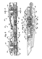
- Fig. 3 is a view of the disc cutterbar as seen along lines 3-3 of Fig. 2, with the extraneous harvester structure removed;
- Fig. 4 is a top plan view of the disc cutterbar seen in Fig. 3;
- Fig. 5 is an enlarged partial cross-sectional view of the disc cutterbar taken along lines 5-5 of Fig. 4;
- Fig. 6 is an enlarged cross-sectional view of the cutterbar taken along lines 6-6 of Fig. 5 to show the structural details of the idler gear mounting apparatus; and
- Fig. 7 is an enlarged partial cross-sectional view of the disc cutterbar taken along lines 7-7 of Fig. 5 to show the structural details of the disc cutter rotor assembly.
- Referring now to the drawings and, particularly, to Fig. 1, a top plan view of a crop harvesting machine, commonly referred to as a disc mower-conditioner, incorporating the principles of the instant invention, can be seen. Any left and right references are used as a matter of convenience and are determined by standing at the rear of the machine and facing in the direction of operative travel. As best seen in Figs. 1 and 2, the disc mower-conditioner 1O is supported over the ground G by a
wheeled frame 12. .The embodiment as shown in the drawings is commonly referred to as a pull-type machine and, therefore, is equipped with adraft tongue 13 and aPTO driveline 14 to input rotational power from a pulling tractor (not shown). - The machine 1O is provided with a
header 15 floatingly supported from theframe 12 in a conventional manner. Theheader 15 is provided with a disc cutterbar 2O, described in further detail below, and aconditioning mechanism 16, including anupper roll 17 and alower roll 18, positioned immediately rearwardly of the cutterbar 2O to receive and condition severed crop. Conditioned crop material which is discharged from theconditioning mechanism 16 is engaged with the rearwardly convergingbaffle shields 19 that deposit this conditioned crop into a consolidated windrow upon the ground G in a conventional manner. - An overall view of the disc cutterbar 2O is best seen in Figs. 3 and 4. The
power input shaft 22 receives rotational power from thePTO driveline 14 and transfers the rotational power through a series of intermeshing power transmission gears described in greater detail below and rotatably powers the operation of thedisc cutter assemblies 25, each of which has a pair of outwardly extendingknives 27 that engage the standing crop material and, by rotation along a circular arc exhibited by thearc 21, affect a severing thereof from the ground. Thedisc cutter assemblies 25 at the respective ends of the cutterbar 2O are provided with a hat-shapeddivider drum 29 to facilitate the flow of crop material over the cutterbar 2O and inwardly toward theconditioning mechanism 16. - Referring now to Figs. 3-7, particularly to Fig. 5, the structural details of the power transmission train 3O and the disc cutterbar 2O can best be seen. Each
disc cutter assembly 25 is provided with a detachably connectedcutter disc 26 which carries theknives 27 for engagement with the standing crop material. Thepower input shaft 22 delivers rotational power to a power tranmission train 3O, including adrive gear 32 associated with each respectivedisc cutter assembly 25 and a pair of idler gears 34 mounted between adjacent drive gears 32. The provision of twoidler gears 34 between adjacent drive gears 32 permits the adjacentdisc cutter assemblies 25 to be rotated in opposing directions. - Referring now to Figs. 5 and 6, the idler gear mounting apparatus 4O can best be seen. The
transmission casing 35 is formed with anindentation 36 in both theupper surface portion 37 and thelower surface portion 38 through which the mountinghole 39 passes. Eachidler gear 34 is rotatably mounted on the apparatus 4O by a bearingassembly 41. The mounting apparatus 4O includes aspacer member 42 having alip portion 43 and ashank portion 44 defining a recessedportion 45. Thespacer member 42 extends completely through the the mountinghole 39 in thetransmission casing 35 and engages both theupper surface portion 37 and thelower surface portion 38 along itsshank portion 44 to provide radial support for thespacer member 42 and thus the mounting apparatus 4O. The inner race of the bearingassembly 41 is mounted on theshank portion 44 of thespacer member 42 between theupper surface portion 37 and thelower surface portion 38. - To fix the mounting apparatus 4O in place on the
transmission casing 35, abolt 46 passes through thespacer member 42 such that thehead portion 47 of thebolt 46 is received within the recessedportion 45 of thespacer member 42. A specially formed securingmember 48 including alip portion 52 for engagement with thelower surface portion 38 of thecasing 35, is threadably engaged with thebolt 46 to tightly draw the mounting apparatus 4O together. The securingmember 48 engages thelower surface portion 38 of thetransmission casing 35 while that thelip portion 43 of thespacer member 42 engages theupper surface portion 37 of thetransmission casing 35 to permit the mounting apparatus 4O to squeeze thecasing 35 against the bearingassembly 41. The special shape of the securingmember 48 fits within theshank portion 44 of thespacer member 42 and extends outwardly thereof to engage with itslip portion 52 thelower surface portion 38 of thecasing 35. O-rings 49 positioned between thelip portion 43 and theupper surface portion 37, as well as between the securingmember 48 and thelower surface portion 38 and between the securingmember 48 and theshank portion 44 seal the idler gear mounting apparatus 4O against thetransmission casing 35 to prevent the loss of lubricating fluid from within thecasing 35. - Referring now to Figs. 5 and 7, the structural configuration of the
disc cutter assembly 25 can best be seen. Thedisc cutter members 26 are detachably mounted to a rotor assembly 5O byfasteners 51. Theupper surface portion 37 of thetransmission casing 35 is provided with an access opening 53 through which the rotor assembly 5O extends into thecasing 35. The rotor assembly 5O includes a bearinghousing 55 detachably mounted on theupper surface portion 37 of thecasing 35 by a plurality ofbolts 56 extending entirely through thetransmission casing 35 and engaging thelower surface portion 38. The bearinghousing 55 mounts a bearingassembly 57 which is removably secured by asnap ring 58 to retain the bearingassembly 57 in place with respect to thehousing 55. - The bearing
assembly 57 rotatably mounts a shaft member 6O for rotation relative to the bearinghousing 55. The shaft member 6O projects both above and below the bearinghousing 55. Ahub 62 is welded to the top of the shaft member 6O for rotation therewith above the bearinghousing 55. Thedisc member 26 is connected to thehub 62 by theaforementioned fasteners 51. Thedrive gear 32 for thedisc cutter assembly 25 is splined onto the bottom of the shaft member 6O and positioned within thetransmission casing 35 for intermeshed engagement with the adjoining idler transmission gears 34. Thedrive gear 32 is secured to the shaft member 6O by a fastener andwasher assembly 65 which is threaded into the shaft member 6O. - The
lower surface portion 38 of thetransmission casing 35 is provided with ahole 67 therein to gain access to the fastener andwasher assembly 65 to permit a disconnection of thedrive gear 32 from the shaft member 6O without removing the rotor assembly 5O from thetransmission casing 35. Thehole 67 is sealed with aseal 68 to maintain the fluid tight integrity of thetransmission casing 35. An O-ring seal 69 is positioned between the bearinghousing 55 and theupper surface portion 37 of thecasing 35 to seal the access opening 53 and prevent leakage therefrom. - The component parts of the rotor assembly 5O can be assembled in the following manner. The bearing
assembly 57 is first pressed into the bearinghousing 55 and retained in place by thesnap ring 58. After supporting the inner race of the bearingassembly 57, the shaft member 6O is pressed through the inner race. Thedrive gear 32 can then be splined onto the shaft member 6O and retained in place by the fastener andwasher assembly 65. Removal of the component parts from an assembled bar can be done by accessing the fastener andwasher assembly 65 through thehole 67 for disconnecting thedrive gear 32 from the shaft member 6O before the rotor assembly 5O is removed from thecasing 35. The bearingassembly 57 can be replaced in the opposite manner from the assembly thereof as described above. - The idler gear mounting apparatus 4O permits a stable, substantial mounting for the
idler gear 34 while also permitting an ease of serviceability to thebearings 41 and gears 34. The rotor assembly 5O permits the cutterbar 2O to retain a low, thin profile to facilitate the flow of severed crop material over the cutterbar 2O. The rotor assembly 5O further also provides adisc cutter assembly 25 that can be easily serviced and permits replacement of any component part thereof. - It will be understood that changes in the details, materials, steps and arrangement of parts which have been described and illustrated to explain the nature of the invention will occur to and may be made by those skilled in the art upon a reading of this disclosure within the principles and scope of the invention. As an example, it will be appreciated by those skilled in the art that the securing
member 48 rather than thespacer member 42 may be provided with a recessedportion 45 for receiving thehead portion 47 of thebolt 46, which, in this case threadably engages with thespacer member 42 rather than with the securingmember 48. - The foregoing detailed description illustrates the preferred embodiment of the invention; however, concepts, as based upon the description may be employed in other embodiments without departing from the scope of the invention. Accordingly, the following claims are intended to protect the invention broadly, as well as in the specific form shown.
- a securing member engaging with the other of said upper and lower surface portions generally in said axial direction to provide axial support for said securing member; and
- a fastener releasably coupling the spacer member and the securing member to each other to tightly fix said mounting apparatus in place relative to the transmission casing.
- the outer race of the bearing assembly is removably engaged with the bearing housing;
- the shaft member is detachably engaged with the inner race of the bearing assembly; and
- the drive gear is detachably connected to the shaft member.
Claims (19)
- a spacer member (42) positioned within a mounting opening (39) through said transmission casing (35) and radially engaging :
- as securing member (48) engaging with the other of said upper and lower surface portions (37, 38) generally in said axial direction to provide axial support for said securing member (48); and
- a fastener (46) releasably coupling the spacer member (42) and the securing member (48) to each other to tightly fix said mounting apparatus (4O) in place relative to the transmission casing (35).
- the spacer member (42) comprises a shank portion (44) radially engaging said upper and lower surface portions (37, 38) of the transmission casing (35) within said mounting opening (39) therein and
- the inner race of the hearing assembly (41) is mounted on the shank portion (44) between the upper and lower surface portions (37, 38) of the transmission casing (35) in a manner to permit the mounting apparatus (4O) to squeeze said inner race between the upper and lower surface portions (37, 38) of said transmission casing (35) at said indentations (36).
- one of said spacer and securing members (42, 48) has a recessed portion (45), and
- the fastener (46) is in the form of a bolt extending through said one of said spacer and securing members (42, 48) and having a head portion (47) engaging said one of said spacer and securing members (42, 48) within said recessed portion (45) and
- said bolt further also threadably engages the other one of said spacer and securing members (42, 48)
characterized in that the mounting apparatus (4O) is of the type as claimed in any one of the claims 1-9.
- said upper surface portion (37) having an opening (53) therein corresponding to each disc cutter assembly (25),
- said transmission casing (35) further also comprising a lower surface portion (38)spaced below the upper surface portion (37) and housing a power transmission gear train (3O) including at least one idler gear (34) positioned between adjacent disc cutter assemblies (25); and
- each said disc cutter assembly (25) comprising :
- the outer race of the bearing assembly (57) is removably engaged with the bearing housing (55);
- the shaft member (6O) is detachably engaged with the inner race of the bearing assembly (57); and
- the drive gear (32) is detachably connected to the shaft member (6O).
Applications Claiming Priority (4)
| Application Number | Priority Date | Filing Date | Title |
|---|---|---|---|
| US84665586A | 1986-03-31 | 1986-03-31 | |
| US846651 | 1986-03-31 | ||
| US846655 | 1986-03-31 | ||
| US06/846,651 US4693061A (en) | 1986-03-31 | 1986-03-31 | Idler gear mounting for disc cutterbars |
Related Child Applications (1)
| Application Number | Title | Priority Date | Filing Date |
|---|---|---|---|
| EP90203045.1 Division-Into | 1990-11-16 |
Publications (3)
| Publication Number | Publication Date |
|---|---|
| EP0240084A2 true EP0240084A2 (en) | 1987-10-07 |
| EP0240084A3 EP0240084A3 (en) | 1988-07-06 |
| EP0240084B1 EP0240084B1 (en) | 1992-09-02 |
Family
ID=27126655
Family Applications (1)
| Application Number | Title | Priority Date | Filing Date |
|---|---|---|---|
| EP19870200586 Expired EP0240084B1 (en) | 1986-03-31 | 1987-03-30 | Gear mounting apparatus and disc cutter rotor assembly |
Country Status (2)
| Country | Link |
|---|---|
| EP (1) | EP0240084B1 (en) |
| DE (1) | DE3781440T2 (en) |
Cited By (4)
| Publication number | Priority date | Publication date | Assignee | Title |
|---|---|---|---|---|
| EP0325548A1 (en) * | 1988-01-22 | 1989-07-26 | Kuhn S.A. | Rotary mower equipped with cutting elements mounted above a housing by means of guiding and driving bearings |
| FR2638056A1 (en) * | 1988-10-26 | 1990-04-27 | Kuhn Sa | MOWER WITH IMPROVED MOUNTING OF CUTTING ORGANS |
| FR2853370A1 (en) | 2003-04-01 | 2004-10-08 | Kuhn Sa | BEARING PROVIDED WITH AN ELASTOMER INSERT AND AGRICULTURAL MACHINE COMPRISING SUCH A BEARING |
| EP4331338A1 (en) * | 2022-08-30 | 2024-03-06 | Talex Spolka Z Ograniczona Opdowiedzialnoscia | Disc mowing device |
Family Cites Families (9)
| Publication number | Priority date | Publication date | Assignee | Title |
|---|---|---|---|---|
| FR1562886A (en) * | 1967-12-22 | 1969-04-11 | ||
| GB1426878A (en) * | 1972-06-14 | 1976-03-03 | Massey Feguson Sa | Belt drives |
| US4141202A (en) * | 1973-12-28 | 1979-02-27 | Multinorm, B.V. | Mowing implement |
| NL171007B (en) * | 1973-12-28 | 1982-09-01 | Multinorm Bv | CUTTING MACHINE. |
| DD117794A1 (en) * | 1975-03-07 | 1976-02-05 | ||
| NL7510686A (en) * | 1975-09-11 | 1977-03-15 | Lely Nv C Van Der | MOWING MACHINE. |
| FR2474811A1 (en) * | 1980-02-04 | 1981-08-07 | Kuhn Sa | PERFECTLY CUTTING BAR |
| NL8101239A (en) * | 1981-03-13 | 1982-10-01 | Multinorm Bv | CUTTING MACHINE WITH SHARED CUTTING BAR. |
| FR2570248B1 (en) * | 1984-09-19 | 1990-06-29 | Kuhn Sa | ROTARY MOWER |
-
1987
- 1987-03-30 EP EP19870200586 patent/EP0240084B1/en not_active Expired
- 1987-03-30 DE DE19873781440 patent/DE3781440T2/en not_active Expired - Fee Related
Cited By (9)
| Publication number | Priority date | Publication date | Assignee | Title |
|---|---|---|---|---|
| EP0325548A1 (en) * | 1988-01-22 | 1989-07-26 | Kuhn S.A. | Rotary mower equipped with cutting elements mounted above a housing by means of guiding and driving bearings |
| FR2626137A1 (en) * | 1988-01-22 | 1989-07-28 | Kuhn Sa | ROTATIONAL MOWER COMPRISING CUTTING DEVICES EXTENDING ABOVE A CARTER THROUGH GUIDE AND TRAINING BEARINGS |
| US4922693A (en) * | 1988-01-22 | 1990-05-08 | Kuhn S.A. | Mower equipped with a cutting bar |
| FR2638056A1 (en) * | 1988-10-26 | 1990-04-27 | Kuhn Sa | MOWER WITH IMPROVED MOUNTING OF CUTTING ORGANS |
| EP0366580A1 (en) * | 1988-10-26 | 1990-05-02 | Kuhn S.A. | Mower with assembly of cutting elements |
| FR2853370A1 (en) | 2003-04-01 | 2004-10-08 | Kuhn Sa | BEARING PROVIDED WITH AN ELASTOMER INSERT AND AGRICULTURAL MACHINE COMPRISING SUCH A BEARING |
| WO2004090356A2 (en) | 2003-04-01 | 2004-10-21 | Kuhn S.A. | Assembly of a bearing provided with an insert on the side of a bush |
| WO2004090356A3 (en) * | 2003-04-01 | 2004-12-16 | Kuhn Sa | Assembly of a bearing provided with an insert on the side of a bush |
| EP4331338A1 (en) * | 2022-08-30 | 2024-03-06 | Talex Spolka Z Ograniczona Opdowiedzialnoscia | Disc mowing device |
Also Published As
| Publication number | Publication date |
|---|---|
| EP0240084A3 (en) | 1988-07-06 |
| DE3781440D1 (en) | 1992-10-08 |
| DE3781440T2 (en) | 1993-02-18 |
| EP0240084B1 (en) | 1992-09-02 |
Similar Documents
| Publication | Publication Date | Title |
|---|---|---|
| US5875619A (en) | Oil slinger for cutter module drive assembly | |
| US5937624A (en) | Disc cutterbar drive module with integral knife stop | |
| US4815262A (en) | Disc cutterbar construction | |
| US5012635A (en) | Modular cutterbar for rotary mower | |
| US4838014A (en) | Disc cutter rotor assembly | |
| CA2228814C (en) | Cutterbar having cutting discs equipped for converging crop | |
| US7730703B1 (en) | Modular disc cutterbar | |
| US5715663A (en) | Crop mover for rotary disc cutter | |
| US4840019A (en) | Disc mower | |
| US4693061A (en) | Idler gear mounting for disc cutterbars | |
| EP0427353A2 (en) | Disc cutter rotor assembly | |
| EP0240084A2 (en) | Gear mounting apparatus and disc cutter rotor assembly | |
| US4211060A (en) | Mowing rotor | |
| US4787196A (en) | Self-cleaning rotor assembly | |
| US4145865A (en) | Machine of mower or mower-conditioner type | |
| EP0158389B1 (en) | Crop lifter for rotary cutting mechanism | |
| CA1285142C (en) | Self-cleaning rotor assembly | |
| CN110089267A (en) | Harvester with the feeding roller driven by hydraulic motor | |
| CA1269846A (en) | Disc cutter rotor assembly | |
| US6205752B1 (en) | Rolling crop guide for disc mower conditioners | |
| US20260068820A1 (en) | Reversible drive cutter module | |
| EP0165624B1 (en) | A mowing machine | |
| US20120210692A1 (en) | Fixed Rotary Knife | |
| CN220087971U (en) | A transmission cover, transmission parts, stem chopper assembly, ear picking table and harvester | |
| CN114586482B (en) | Paddy field beating grass breaking grass winding preventing cutter optimal design mechanism |
Legal Events
| Date | Code | Title | Description |
|---|---|---|---|
| PUAI | Public reference made under article 153(3) epc to a published international application that has entered the european phase |
Free format text: ORIGINAL CODE: 0009012 |
|
| 17P | Request for examination filed |
Effective date: 19870401 |
|
| AK | Designated contracting states |
Kind code of ref document: A2 Designated state(s): DE FR GB |
|
| PUAL | Search report despatched |
Free format text: ORIGINAL CODE: 0009013 |
|
| AK | Designated contracting states |
Kind code of ref document: A3 Designated state(s): DE FR GB |
|
| RAP1 | Party data changed (applicant data changed or rights of an application transferred) |
Owner name: FORD NEW HOLLAND, INC. (A DELAWARE CORP.) |
|
| 17Q | First examination report despatched |
Effective date: 19900806 |
|
| GRAA | (expected) grant |
Free format text: ORIGINAL CODE: 0009210 |
|
| AK | Designated contracting states |
Kind code of ref document: B1 Designated state(s): DE FR GB |
|
| XX | Miscellaneous (additional remarks) |
Free format text: TEILANMELDUNG 90203045.1 EINGEREICHT AM 30/03/87. |
|
| REF | Corresponds to: |
Ref document number: 3781440 Country of ref document: DE Date of ref document: 19921008 |
|
| ET | Fr: translation filed | ||
| PG25 | Lapsed in a contracting state [announced via postgrant information from national office to epo] |
Ref country code: GB Effective date: 19930330 |
|
| PLBE | No opposition filed within time limit |
Free format text: ORIGINAL CODE: 0009261 |
|
| STAA | Information on the status of an ep patent application or granted ep patent |
Free format text: STATUS: NO OPPOSITION FILED WITHIN TIME LIMIT |
|
| 26N | No opposition filed | ||
| GBPC | Gb: european patent ceased through non-payment of renewal fee |
Effective date: 19930330 |
|
| PG25 | Lapsed in a contracting state [announced via postgrant information from national office to epo] |
Ref country code: FR Effective date: 19931130 |
|
| PG25 | Lapsed in a contracting state [announced via postgrant information from national office to epo] |
Ref country code: DE Effective date: 19931201 |
|
| REG | Reference to a national code |
Ref country code: FR Ref legal event code: ST |