EP4491886A1 - Vorrichtung zur mechanischen befestigung eines moduls an einer wand eines gerätes mit einer das modul aufnehmenden montageöffnung - Google Patents
Vorrichtung zur mechanischen befestigung eines moduls an einer wand eines gerätes mit einer das modul aufnehmenden montageöffnung Download PDFInfo
- Publication number
- EP4491886A1 EP4491886A1 EP23185285.6A EP23185285A EP4491886A1 EP 4491886 A1 EP4491886 A1 EP 4491886A1 EP 23185285 A EP23185285 A EP 23185285A EP 4491886 A1 EP4491886 A1 EP 4491886A1
- Authority
- EP
- European Patent Office
- Prior art keywords
- module
- snap
- locking frame
- module carrier
- base body
- Prior art date
- Legal status (The legal status is an assumption and is not a legal conclusion. Google has not performed a legal analysis and makes no representation as to the accuracy of the status listed.)
- Granted
Links
Images




Classifications
-
- H—ELECTRICITY
- H05—ELECTRIC TECHNIQUES NOT OTHERWISE PROVIDED FOR
- H05K—PRINTED CIRCUITS; CASINGS OR CONSTRUCTIONAL DETAILS OF ELECTRIC APPARATUS; MANUFACTURE OF ASSEMBLAGES OF ELECTRICAL COMPONENTS
- H05K5/00—Casings, cabinets or drawers for electric apparatus
- H05K5/02—Details
- H05K5/0217—Mechanical details of casings
-
- F—MECHANICAL ENGINEERING; LIGHTING; HEATING; WEAPONS; BLASTING
- F16—ENGINEERING ELEMENTS AND UNITS; GENERAL MEASURES FOR PRODUCING AND MAINTAINING EFFECTIVE FUNCTIONING OF MACHINES OR INSTALLATIONS; THERMAL INSULATION IN GENERAL
- F16B—DEVICES FOR FASTENING OR SECURING CONSTRUCTIONAL ELEMENTS OR MACHINE PARTS TOGETHER, e.g. NAILS, BOLTS, CIRCLIPS, CLAMPS, CLIPS OR WEDGES; JOINTS OR JOINTING
- F16B5/00—Joining sheets or plates, e.g. panels, to one another or to strips or bars parallel to them
- F16B5/06—Joining sheets or plates, e.g. panels, to one another or to strips or bars parallel to them by means of clamps or clips
- F16B5/0607—Joining sheets or plates, e.g. panels, to one another or to strips or bars parallel to them by means of clamps or clips joining sheets or plates to each other
- F16B5/0621—Joining sheets or plates, e.g. panels, to one another or to strips or bars parallel to them by means of clamps or clips joining sheets or plates to each other in parallel relationship
- F16B5/065—Joining sheets or plates, e.g. panels, to one another or to strips or bars parallel to them by means of clamps or clips joining sheets or plates to each other in parallel relationship the plates being one on top of the other and distanced from each other, e.g. by using protrusions to keep contact and distance
-
- F—MECHANICAL ENGINEERING; LIGHTING; HEATING; WEAPONS; BLASTING
- F16—ENGINEERING ELEMENTS AND UNITS; GENERAL MEASURES FOR PRODUCING AND MAINTAINING EFFECTIVE FUNCTIONING OF MACHINES OR INSTALLATIONS; THERMAL INSULATION IN GENERAL
- F16M—FRAMES, CASINGS OR BEDS OF ENGINES, MACHINES OR APPARATUS, NOT SPECIFIC TO ENGINES, MACHINES OR APPARATUS PROVIDED FOR ELSEWHERE; STANDS; SUPPORTS
- F16M11/00—Stands or trestles as supports for apparatus or articles placed thereon ; Stands for scientific apparatus such as gravitational force meters
- F16M11/02—Heads
- F16M11/04—Means for attachment of apparatus; Means allowing adjustment of the apparatus relatively to the stand
-
- F—MECHANICAL ENGINEERING; LIGHTING; HEATING; WEAPONS; BLASTING
- F16—ENGINEERING ELEMENTS AND UNITS; GENERAL MEASURES FOR PRODUCING AND MAINTAINING EFFECTIVE FUNCTIONING OF MACHINES OR INSTALLATIONS; THERMAL INSULATION IN GENERAL
- F16B—DEVICES FOR FASTENING OR SECURING CONSTRUCTIONAL ELEMENTS OR MACHINE PARTS TOGETHER, e.g. NAILS, BOLTS, CIRCLIPS, CLAMPS, CLIPS OR WEDGES; JOINTS OR JOINTING
- F16B21/00—Means for preventing relative axial movement of a pin, spigot, shaft or the like and a member surrounding it; Stud-and-socket releasable fastenings
- F16B21/06—Releasable fastening devices with snap-action
- F16B21/08—Releasable fastening devices with snap-action in which the stud, pin, or spigot has a resilient part
- F16B21/086—Releasable fastening devices with snap-action in which the stud, pin, or spigot has a resilient part the shank of the stud, pin or spigot having elevations, ribs, fins or prongs intended for deformation or tilting predominantly in a direction perpendicular to the direction of insertion
-
- F—MECHANICAL ENGINEERING; LIGHTING; HEATING; WEAPONS; BLASTING
- F16—ENGINEERING ELEMENTS AND UNITS; GENERAL MEASURES FOR PRODUCING AND MAINTAINING EFFECTIVE FUNCTIONING OF MACHINES OR INSTALLATIONS; THERMAL INSULATION IN GENERAL
- F16M—FRAMES, CASINGS OR BEDS OF ENGINES, MACHINES OR APPARATUS, NOT SPECIFIC TO ENGINES, MACHINES OR APPARATUS PROVIDED FOR ELSEWHERE; STANDS; SUPPORTS
- F16M11/00—Stands or trestles as supports for apparatus or articles placed thereon ; Stands for scientific apparatus such as gravitational force meters
- F16M11/02—Heads
- F16M11/16—Details concerning attachment of head-supporting legs, with or without actuation of locking members thereof
-
- H—ELECTRICITY
- H05—ELECTRIC TECHNIQUES NOT OTHERWISE PROVIDED FOR
- H05K—PRINTED CIRCUITS; CASINGS OR CONSTRUCTIONAL DETAILS OF ELECTRIC APPARATUS; MANUFACTURE OF ASSEMBLAGES OF ELECTRICAL COMPONENTS
- H05K5/00—Casings, cabinets or drawers for electric apparatus
- H05K5/0017—Casings, cabinets or drawers for electric apparatus with operator interface units
Definitions
- the invention relates to a device for mechanically fastening a module to a wall of a device with a mounting opening receiving the module.
- UI user interface
- the UI module is, for example, a membrane keyboard, a touchscreen, a combination of PCBA ( printed circuit board assembly ) and input elements such as rotary knobs or membrane keys.
- the construction of the module and the wall with the device's mounting opening is carried out and customized individually as part of the respective device development. This customization leads to a correspondingly high level of effort for design, testing and optimization for each construction.
- Screw connections are detachable connections that are designed differently in many cases. As a result, a large number of tools must be kept on hand for production and service. Screw connections also have the disadvantage that installation space is lost in order to ensure access to the screw connections for screwing tools.
- Bonding the module to the housing has the disadvantage that the final bonding result is only visible some time (up to several hours) after bonding. This can be a hindrance to assembly and servicing.
- reliable bonding requires special manufacturing know-how. Disassembly is not possible without causing damage when bonding. In the event of damage, entire device parts may have to be replaced with the UI module in order to correct a fault.
- a snap connection of the module directly to the device requires precise coordination of the module and the mounting opening, including tolerances and tools, which leads to a high level of development effort.
- Each injection molding tool for the device part with the mounting opening requires complex coordination with the tool or the design for the UI module in order to integrate the UI module. This disadvantage is particularly evident in medium and small quantities.
- the CN 108800734 A describes a touch panel display that is attached to a bracket with snap hooks.
- the bracket is inserted into an opening in a housing cover and the snap hooks are snapped into the snap receptacles of the housing cover.
- the snap connection between the bracket and the housing cover requires the components to be precisely coordinated with one another.
- the invention is based on the object of providing a device for mechanically fastening a module to a wall of a device with a mounting opening that accommodates the module, in which the effort for coordinating the components with one another and the tools required for production is reduced.
- the module carrier with its plate-shaped base body can be inserted into the mounting opening of the device.
- the module is arranged on the front of the base body and fastened to the module carrier.
- the module or the module carrier has a support plate with which the module carrier or the module can be supported on the front side of the wall with the mounting opening of the device.
- the locking frame has a frame opening into which the rear part of the base body can be inserted.
- the device comprises at least one spring element which is designed and arranged to resiliently support the locking frame on the rear side of the wall next to the mounting opening and/or to resiliently support the support plate on the front side of the wall.
- the module carrier has at least one first snap element on the outer circumference of the base body and the locking frame has at least one second snap element on the inner circumference.
- the first snap element and the second snap element are designed so that they can be snapped together when the base body is inserted into the frame opening.
- the first snap element and the second snap element are snapped together, there is a gap between the back of the support plate and the front of the locking frame to accommodate an edge area of the wall surrounding the mounting opening. This makes it possible to first insert the module carrier into the mounting opening and then with the rear part of the locking frame into the frame opening or to slide the locking frame with the frame opening onto the rear part of the base body.
- the edge area of the wall surrounding the mounting opening is arranged between the back of the support plate and the front of the locking frame.
- the support plate is supported on the front side of the wall and the locking frame is supported on the rear side of the wall via the spring element and/or
- the support plate is attached to the spring element on the front side of the wall and the locking frame is attached to the rear side of the wall.
- the device is fixed to the device by engaging the module carrier in the mounting opening and clamping the support plate and the locking frame using the spring element on the front and rear sides of the wall.
- Tolerances between the module carrier, support plate, locking frame and wall components can be compensated by varying elastic deformation of the spring element.
- Precise coordination of the module carrier and mounting opening is not important, since the module carrier only has to be able to be inserted into the mounting opening with the base body and the support plate covers the gap between the base body and the mounting opening.
- the wall thickness of the wall and the mounting opening in the housing can be roughly tolerated. The tolerances of the wall thickness are compensated by the elastic deformation of the spring elements and the gaps that remain between the wall opening and the base body engaging in it due to the tolerances are covered by the support plate.
- the accuracies are laid in the module carrier and the locking frame of the device.
- the snap connection between the module carrier and the locking frame can be designed to be detachable so that disassembly is possible.
- the snap connection can be designed in such a way that the components can be mounted and/or dismantled on the wall without special tools.
- the device can be designed in such a way that the module carrier and locking frame or one of the two above components can be used for different devices. This makes it possible to use more identical parts for different devices. If one of the two components has to be specifically adapted to different devices, only minor changes may be necessary. This is the case, for example, if the module carrier is specifically adapted to the intended module. or the device needs to be adjusted. In addition, the snap connection makes assembly and servicing easier and faster. Since the tolerance compensation is achieved by supporting the spring element on the wall of the device, the forces between the first snap element and the second snap element are not or only insignificantly influenced by the tolerance compensation.
- the support plate is connected to the module carrier, the clamping forces are diverted via the module carrier and kept away from the module. This can be particularly advantageous for sensitive modules, for example displays with a cover glass. If the support plate is connected to the module, this can improve the design because the module lies closely against the housing wall and is not surrounded by the edge of a support plate of the module carrier.
- the support plate is connected in one piece to the module carrier or in one piece to the module. This can simplify manufacture and assembly. If it is designed in one piece with the module carrier, the support plate can be designed in the form of a frame that is connected on the inner circumference to a base body that projects to the rear. The frame can define a recess that accommodates the module. If it is designed in one piece with the module, the support plate can be designed as a laterally protruding edge region of a cover glass of a touch panel or other module.
- the module carrier and the locking frame are rectangular or circular.
- Modules for use in devices are often rectangular or circular and the rectangular or circular design of the device enables good adaptation and space-saving attachment of the device to the device.
- the module carrier has a recess on the front and the module is inserted into the recess.
- the recess enables the module to be housed on the module carrier in a protected and space-saving manner.
- the recess is a window opening in the support plate and/or a depression in the base body of the module carrier.
- the module is connected to the module carrier via an adhesive connection.
- This allows the module to be attached to the module carrier without stress.
- Other ways of attaching the module to the module carrier are also possible, for example by clamping the module to the module carrier, by screwing it tight or securing the module to the module carrier with locking rings or other securing devices. Different types of attachment can also be combined.
- the base body has a ribbed plate. This makes it possible to achieve a stable base body with minimal use of material. A stable base body can prevent damage to a module due to forces acting on the module carrier.
- the module is a display, a monitor, a keyboard, a touchscreen, another UI module or a transparent pane.
- the module can in particular be designed as a touch panel.
- the transparent pane can in particular be a viewing window, for example a disc on a centrifuge.
- an electronic board is arranged on the back of the base body.
- the electronic board can be an electronic control and/or a power supply for an electronic module attached to the module carrier.
- screw domes protrude from the back of the base body and the electronic board is attached to screw holes using screws on the screw domes. This ensures that the electronic board is securely attached and is easy to install and service.
- positioning lugs protrude from the back of the base body and the electronic board is guided to positioning holes on the positioning lugs. This ensures that the electronic board is precisely aligned with the module carrier.
- the module carrier has at least one snap hook protruding to the rear on the outer circumference and the locking frame has at least one snap receptacle for the snap hook on the inner circumference and/or the locking frame has at least one snap hook protruding to the front on the inner circumference and the module carrier has at least one snap receptacle for the snap hook on the outer circumference.
- the snap hooks can be formed exclusively on the module carrier and the snap receptacles exclusively on the locking frame or vice versa.
- both components can have both snap hooks and snap receptacles, with the arrangement of the snap hooks and snap receptacles being coordinated so that A snap hook of one component can always be snapped into a snap receptacle of the other component.
- the locking frame has the snap hooks and the module carrier has the snap receptacles.
- the protruding snap hooks are more sensitive snap elements than the snap receptacles, since the snap hooks are deflected sideways before snapping.
- the arrangement of the locking hooks on the locking frame has the advantage that the more sensitive snap elements are arranged on the component, which is particularly well suited as an identical part for use on different devices and for cost-effective production in high quantities.
- the snap hook has a one- or two-armed lever with a first lever arm with a hook for snapping into a snap receptacle and a second lever arm for releasing the snap connection with the snap receptacle.
- This is advantageous for service because it makes disassembly easier without the use of tools.
- service can open the device.
- the lever has the second lever arm at the rear end. This makes it easier to operate the lever when the device is open.
- the module carrier and/or the locking frame has snap-in receptacles (locking receptacles) at several locking positions arranged one behind the other in a perpendicular direction to the plate-shaped base body.
- This enables the module carrier and the locking frame to be locked together in different locking positions in which there are different distances between the back of the support plate and the front of the locking frame.
- This enables the device to be used with different Devices where the wall with the mounting opening has different thicknesses.
- rough tolerances in the wall thickness of a device can be covered by different locking steps.
- the module carrier has several first snap elements on the outer circumference and the locking frame has several second snap elements on the inner circumference. This means that the forces acting when snapping into the individual snap connections can be kept low and the device can be clamped evenly to the wall of the device.
- the module carrier has only a single first snap element and the locking frame has only a single second snap element, with the first snap element running completely around the outer circumference of the module carrier and the second snap element running completely around the inner circumference of the locking frame.
- the module carrier has several symmetrically arranged first snap elements on the outer circumference and the locking frame has several symmetrically arranged second snap elements on the inner circumference. This promotes uniform clamping of the device to the device.
- the spring element protrudes from the front of the locking frame.
- assembly and disassembly can be made easier.
- arranging the spring element on the rear side of the wall a gap between the device and the wall caused by tolerance compensation can be concealed.
- the locking frame has at least one spring element designed as a spiral spring on the front side, which is inclined at an acute angle to the plane of the frame.
- the design of the spring element as an inclined spiral spring is particularly advantageous in terms of production technology when manufactured by injection molding from plastic.
- the locking frame has several symmetrically arranged spring elements. This is advantageous for uniform installation and for compensating for different manufacturing tolerances on the circumference of the mounting opening.
- the invention also includes embodiments in which the locking frame has only a single spring element, which can be formed, for example, by a circumferential, forward-protruding, possibly outward-slanting elastic lip on the front of the locking frame.
- the support plate has the spring element.
- the spring element is formed, for example, by a circumferential, possibly outwardly inclined, rearwardly projecting elastic lip on the outer circumference of the support plate or by a support plate designed as a disc spring made of elastic material.
- the spring element is formed by a ring made of an elastomer, which is positioned between the locking frame and the rear side of the wall or between the support plate and the front side of the wall.
- the ring can, for example, be guided on the circumference of the base body and positioned on the rear side of the wall or on the front side of the wall.
- the ring can be designed as a rectangular ring or as a circular ring. In principle, an O-ring can be used for this.
- the snap hook is formed in one piece with the module carrier or with the locking frame and/or the snap receptacle is formed in one piece with the locking frame or the module carrier and/or the spring element is formed in one piece with the locking frame or the support plate.
- the integral design of the structures mentioned with the components mentioned facilitates manufacture and assembly. Manufacture can be carried out in particular by injection molding from plastic. Preferably, both the module carrier and the locking frame are injection molded in one piece from plastic.
- the module carrier is made of plastic or metal and/or the locking frame is made of plastic.
- the module carrier is made of die-cast aluminum or milled metal.
- the module carrier is injection-molded from plastic and/or the locking frame is injection-molded from plastic (but can also be a 2-component injection-molded part made of hard and soft components to realize a sealing function).
- the module carrier is formed in one piece and/or the locking frame is formed in one piece.
- the wall and/or a housing of the device having the wall is made of metal or plastic. TSG, for example, is used as the plastic.
- the housing is injection-molded from plastic.
- front and “rear” and terms comprising these directional terms refer to an arrangement of the device on an outer wall of a device in which the module is arranged on the outside of the device, its outside being visible to an observer looking at the device from outside and the locking frame is arranged on the inside of the outer wall of the device.
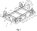
- a module carrier 1 has a rectangular, plate-shaped base body 2.
- the base body 2 has a plate 3 and intersecting ribs 4.1, 4.2 protruding from the back of the plate 3.
- the ribs 4.1, 4.2 have hook-shaped projections 5.1, 5.2 at some of their outer ends, protruding backwards with outer edges aligned perpendicular to the plate 3.
- the base body 2 has first snap elements 6 on the outer circumference, which are designed as snap hooks 7 projecting vertically backwards from the base plate.
- the snap hooks 7 each have a strip-shaped section 7.1. At a distance from the base body 2, a hook 7.2 protrudes outwards from the strip-shaped section 7.1 in the form of a bar inclined at an acute angle to the strip-shaped section 7.1. The hook 7.2 is arranged at a distance from the rear end of the strip-shaped section 7.1. At the rear end, the strip-shaped section 7.1 has a bevel 7.3 on the outside.
- the snap hook 7 forms a one-armed lever with a shorter first lever arm 7.4 and a longer second lever arm 7.5, which can be pivoted by pressing against the outside of the second lever arm 7.5.
- Two snap hooks 7 are arranged on each of the two long sides of the base body 2 and one snap hook 7 is arranged on each of the two short sides of the base body 2.
- Strip-shaped side walls 8.1-8.4 of the base body 2 protrude vertically forward from the lateral edges of the plate 3 of the base body 2, which define a recess in the form of a depression 9 on the front of the base body 2.
- the depression 9 serves for inserting a module.
- two diagonally arranged screw domes 10 and two also diagonally arranged positioning lugs 11 protrude to the rear, each of which is supported by a lateral ribbing 12 on the rear side of the plate 3.
- the plate-shaped base body 3 On the inner sides of the snap hooks, the plate-shaped base body 3 has rectangular first openings 13 for manufacturing reasons and to improve the elasticity of the snap hooks.
- the module carrier 1 is manufactured in one piece by injection molding.
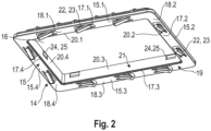
- a locking frame 14 has a rectangular frame body 15 with four frame sides 15.1-15.4 that delimit a frame opening 16.
- the frame sides 15.1-15.4 are each L-profiles 17.1-17.4.
- First legs 18.1-18.4 of the L-profiles 17.1-17.4 fall into the main plane (plane of greatest extension) of the locking frame 14 and together form a contact section 19 of the locking frame 14.
- Second legs 20.1-20.4 of the L-profile 17.1-17 extend from the edge of the frame opening 16 vertically to the main plane of the locking frame 14 and together form a connecting section 21 of the locking frame 14.
- the contact section 19 has spring elements 22 on the front in the form of bending springs 23 inclined at an acute angle to the main plane.
- Three bending springs 23 are arranged on each of the two long frame sides 15.1, 15.3 of the locking frame 14 and two bending springs 23 are arranged on each of the two short frame sides 15.2, 15.4 of the locking frame 14.
- the bending springs 23 are essentially evenly distributed over the sides of the contact section 19.
- the connecting section 21 has second snap elements 24 in the form of snap receptacles on the inner circumference.
- the snap receptacles 25 are arranged on the front edge of the connecting section 21.
- Two snap receptacles 25 are arranged on each of the two long frame sides 15.1, 15.3 and only one snap receptacle 25 is arranged on each of the two short frame sides 15.2, 15.4.
- the locking frame 14 is injection-molded from one piece of plastic.
- the recess 9 of the module carrier 1 serves to accommodate a touch panel or another module.
- a module 26 is inserted into the recess 9, wherein the module 26 has a support plate 27, for example in the form of a display glass which projects outwards in the sides of the base body 2 parallel to the main plane (plane of greatest extension) of the base body 2.
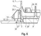
- Fig. 6 which has the same module carrier 1 as in Fig. 1 and one of Fig. 2 deviating locking frame 14, the module 26 is shown in the recess 9.
- the module 26 is attached to the module carrier 1 by means of an adhesive connection.
- a rectangular electronic board 28 with holes in the corners can be mounted on the back of the module carrier 1, whereby the positioning lugs 11 are inserted into two positioning holes arranged diagonally on the electronic board 28 and screws 29 are inserted through the two diagonally arranged screw holes and screwed into the screw domes 10. In the present embodiment, this is omitted and in the Fig. 11 to 13 shown for another embodiment.
- the module carrier 1 and the locking frame 14 are aligned with a rectangular assembly opening 30 in a wall 31 of a housing 32 of a device.
- the wall 31 can be an outer wall of a housing 32.
- the wall 31 can also be an inner wall of a device, for example a wall that separates two functional areas of the device from each other.
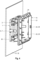
- the module carrier 1 with the base body 2 is inserted into the mounting opening 30 until the support plate 27 rests on the front side of the wall 31.
- the locking frame 14 is pushed onto the module carrier 1 from behind until the spring elements 22 are supported on the rear side of the wall 31, compress slightly and the snap hooks 7 snap into the snap receptacles 25.
- Fig. 5 the device is shown in the installed position, in which the module carrier 1 and the locking frame 14 are snapped together and the spring elements 22 are elastically deformed and supported on the wall 31.
- the device 33 consisting of module carrier 1, module 26 and locking frame 14 is clamped to the outer edge of the mounting opening 30 on the wall 31.
- the manufacturing tolerances of the device 33 and the wall 31 are compensated by the spring elements 22. Precise coordination of the mounting opening 30 and the module carrier 1 is not important, since the support plate 27 covers the gap between the mounting opening 30 and the module carrier 1 on the outside.
- the device 33 can be installed extremely easily and without tools. It can also be removed easily and without tools. To do this, the opposing snap hooks 7 of the module carrier 1 can be pressed together slightly at the rear ends until the hooks 7.2 are released from the snap receptacles 25. The locking frame 14 can then be pulled off the module carrier 1 and the module carrier 1 can be removed from the installation opening 30.
- the embodiment of Fig. 6 to 8 differs from the embodiment of Fig. 1 to 5 in that the connecting section 21 of the The locking frame 14 has snap-in receptacles 25.1, 25.2, 25.3 at several locking positions arranged one behind the other in a perpendicular direction to the contact section 19.
- the module carrier 1 and the locking frame 14 can be snapped or locked together in different locking positions. This is advantageous for a rough compensation of manufacturing tolerances and for the use of the device 33 with different devices in which the mounting opening 30 is formed in walls 31 with different wall thicknesses.
- each snap-in receptacle 25.1, 25.2, 25.3 are inclined rearwardly in accordance with the inclination of the rear side of each hook 7.2 in order to facilitate the displacement of the locking frame 14 into a subsequent locking position.
- this embodiment has an outer step 34 on the front side of the wall 31, which runs around the mounting opening 30 and is dimensioned to accommodate the support plate 27.
- the front side of the support plate 27 is flush with the front side of the wall 31 next to the outer step 34.
- the gap between the outer circumference of the support plate 27 and the outer boundary of the outer step can be kept small.
- the embodiment of Fig. 9 to 13 differs from the embodiment of Fig. 1 to 5 in that the first snap elements 6 of the module carrier 1 are designed as snap receptacles 25 and not as snap hooks and that the second snap elements 24 of the locking frame are designed as snap hooks 7 and not as snap receptacles.
- the support plate 27 is formed integrally with the module carrier 1 and not with the module 26.
- the module carrier 1 has the snap-in receptacles 25 on the outer circumference of the strip-shaped side walls 8.1-8.4.
- the snap-in receptacles 25 are designed as rectangular second openings 35 in the module carrier 1.
- Two snap-in receptacles 25 are arranged on each of the two long sides of the base body 2 and one snap-in receptacle 25 is arranged on each of the two short sides of the base body 2.
- the base body 2 On the rear side, the base body 2 has insertion bevels 36 projecting to the rear in addition to the snap-in receptacles 25.
- the insertion bevels 36 are formed on the outer sides of parallel cams 37.1, 37.2 projecting to the rear, which are connected to one another by a connecting web.
- the support plate 27 is a rectangular frame 38 with a window opening 39 at the front.
- the support plate 39 is connected at the edge of the window opening 39 in one piece with the front edge of the strip-shaped side walls 8.1-8.4 surrounding the recess 9 and protrudes outwards parallel to the main plane of the base body 2.
- the window opening 39 and the recess 9 together form a recess 40 for inserting and wiring a module 26.
- the base body 2 can have through-openings in order to connect an electronic module on the front of the base body with an electronic board on the back of the base body or with electronics in the device by means of cables passed through.
- the module carrier 1 is injection-molded from one piece of plastic.
- the locking frame has the snap hooks 7 on the inner circumference.
- Each snap hook 7 is connected to the front edge of the connecting section 21 via a connecting tab 41.
- Each snap hook 7 has a strip-shaped section 7.1 which extends perpendicularly to the contact section 19 and has an inwardly projecting hook 7.2 at the front end.
- the connecting tab 41 is connected to the middle of the strip-shaped section 7.1.
- the snap hook 7 is thus designed as a two-armed lever, with a first lever arm 7.4 from the hook 7.2 to the connecting tab 41 and a second lever arm 7.5 from the connecting tab 41 to the rear end of the strip-shaped section 7.1, which can be pivoted by actuating the second lever arm 7.5.
- the bending springs 23 are arranged on the front side of the locking frame 14 above wedge-shaped notches 42 of the contact section 19, so that the bending springs 23 are each connected to the contact section 19 above the deepest point of the notch 42. This arrangement is chosen to increase the fatigue strength and for manufacturing reasons.
- the locking frame 14 is injection-molded from one piece of plastic.
- a module On the front side of the module carrier 1, a module is glued into the recess 40, which is not visible in the figures.
- an electronic board 28 On the back side of the module carrier 1, according to Fig. 11 to 13 an electronic board 28 is fixed.
- the module carrier 1 and the locking frame 14 are arranged on different sides of the mounting opening 30 and aligned with it.
- the module carrier 1 is inserted into the mounting opening 30 until the support plate 27 rests against the front side of the wall 31.
- the spring elements 22 compensate for tolerances of the components 1, 14, 31 involved.
- the support plate 27 covers the edge area of the assembly opening 30, so that it is not important that the module carrier 1 is precisely adjusted to the assembly opening 30. Assembly can be carried out without the use of tools. Disassembly is also easy by slightly pivoting the rear ends of opposing snap hooks 7 together. As soon as the hooks 7.2 are released from the snap receptacles 25, the locking frame 14 can be pulled off the module carrier 1. The module carrier 1 can then be removed from the assembly opening 30.
- a further advantage is that the snap hooks 7 are components of the locking frame 14, so that in the event of failure the locking frame 14 must be replaced.
- the locking frame 14 can preferably be used as an identical part for different devices, so that replacing this component is comparatively inexpensive.
Landscapes
- Engineering & Computer Science (AREA)
- General Engineering & Computer Science (AREA)
- Mechanical Engineering (AREA)
- Microelectronics & Electronic Packaging (AREA)
- Casings For Electric Apparatus (AREA)
Abstract
Description
- Die Erfindung betrifft eine Vorrichtung zur mechanischen Befestigung eines Moduls an einer Wand eines Gerätes mit einer das Modul aufnehmenden Montageöffnung.
- Laborgeräte wie Shaker, Inkubatoren, Cycler, Thermomischer, Zentrifugen, Automaten und Geräte für andere Anwendungsbereiche weisen vielfach ein User Interface (UI)-Modul auf, das in eine Montageöffnung einer Wand des Gerätes eingesetzt und an der Wand befestigt ist. Das UI-Modul ist beispielsweise eine Folientastatur, ein Touchscreen, eine Kombination aus PCBA (printed circuit board assembly) und Eingabeelementen wie Drehknöpfe oder Folientasten.
- Bekannt ist, das UI-Modul in eingesetzter Stellung in der Montageöffnung durch Schrauben und/oder Verkleben zu fixieren. Ferner ist bekannt, das Modul direkt in einer Montageöffnung des Gerätes zu verklipsen.
- Die Konstruktion des Moduls und der Wand mit der Montageöffnung des Gerätes wird individuell im Rahmen der jeweiligen Geräteentwicklung durchgeführt und individualisiert. Diese Individualisierung führt bei jeder Konstruktion zu einem entsprechend hohen Aufwand für Gestaltung, Prüfung und Optimierung.
- Die bekannten Verschraubungen des Moduls sind lösbare Verbindungen, die in vielen Fällen unterschiedlich ausgeführt sind. Infolgedessen ist eine hohe Anzahl vorzuhaltender Werkzeuge bei Produktion und Service erforderlich. Verschraubungen haben zudem den Nachteil, dass Bauraum verlorengeht, um den Zugang der Verschraubungen für Schraubwerkzeuge zu gewährleisten.
- Eine Verklebung des Moduls mit dem Gehäuse hat den Nachteil, dass das finale Klebeergebnis erst einige Zeit (bis zu mehrere Stunden) nach der Verklebung zur Verfügung steht, was hinderlich bei Montage und Service sein kann. Zudem erfordert eine verlässliche Verklebung spezielles Fertigungs-Know-how. Eine Demontage ist beim Kleben nicht zerstörungsfrei möglich. Gegebenenfalls müssen im Schadensfall ganze Geräteteile mit dem UI-Modul ausgetauscht werden, um einen Fehler zu beheben.
- Eine Schnappverbindung des Moduls direkt mit dem Gerät erfordert eine genaue Abstimmung des Moduls und der Montageöffnung einschließlich der Toleranzen und Werkzeuge, was zu einem hohen Aufwand in der Entwicklung führt. Jedes Spritzgusswerkzeug für das Geräteteil mit der Montageöffnung bedarf zur Integration des UI-Moduls einer aufwändigen Abstimmung mit dem Werkzeug oder dem Design für das UI-Modul. Dieser Nachteil kommt insbesondere bei mittleren und kleinen Stückzahlen zum Tragen.
- Die
CN 108800734 A beschreibt ein Touchpanel-Display, das an einer Halterung mit Schnapphaken befestigt ist. Die Halterung ist in eine Öffnung einer Gehäuseabdeckung eingesetzt und die Schnapphaken sind mit Schnappaufnahmen der Gehäuseabdeckung verschnappt. Die Verschnappung zwischen Halterung und Gehäuseabdeckung erfordert eine präzise Abstimmung der Bauteile aufeinander. - Davon ausgehend liegt der Erfindung die Aufgabe zugrunde, eine Vorrichtung zur mechanischen Befestigung eines Moduls an einer Wand eines Gerätes mit einer das Modul aufnehmenden Montageöffnung zur Verfügung zu stellen, bei der der Aufwand für die Abstimmung der Bauteile aufeinander und der für die Fertigung erforderlichen Werkzeuge verringert ist.
- Die Aufgabe wird erfindungsgemäß durch eine Vorrichtung gemäß Anspruch 1 gelöst. Vorteilhafte Ausführungsarten der erfindungsgemäßen Vorrichtung sind in Unteransprüchen und in der Beschreibung angegeben.
- Die erfindungsgemäße Vorrichtung zur mechanischen Befestigung eines Moduls an einer Wand eines Gerätes mit einer das Modul aufnehmenden Montageöffnung umfasst:
- einen Modulträger, der einen plattenförmigen Grundkörper zum Einsetzen in die Montageöffnung und mindestens ein erstes Schnappelement am Außenumfang des Grundkörpers aufweist,
- ein Modul, das auf der Vorderseite des Grundkörpers angeordnet und am Modulträger befestigt ist,
- eine Stützplatte zum Abstützen auf einer vorderen Seite der Wand mit der Montageöffnung, die mit dem Modulträger oder Modul verbunden ist und parallel zur Hauptebene des Grundkörpers nach außen vorsteht,
- einen Rastrahmen, der eine Rahmenöffnung zum Einsetzen eines hinteren Teils des Grundkörpers und mindestens ein zweites Schnappelement am Innenumfang aufweist,
- mindestens ein Federelement, das ausgebildet und angeordnet ist, den Rastrahmen federnd auf der hinteren Seite der Wand neben der Montageöffnung abzustützen und/oder die Stützplatte federnd auf der vorderen Seite der Wand abzustützen,
- wobei das erste Schnappelement und das zweite Schnappelement ausgebildet sind, miteinander zu verschnappen, wenn der Grundkörper in die Rahmenöffnung eingesetzt ist, wobei zwischen der Rückseite der Stützplatte und der Vorderseite des Rastrahmens ein Abstand zur Aufnahme eines die Montageöffnungen umgebenden Randbereichs der Wand vorhanden ist.
- Bei der erfindungsgemäßen Vorrichtung ist der Modulträger mit seinem plattenförmigen Grundkörper in die Montageöffnung des Gerätes einsetzbar. Das Modul ist auf der Vorderseite des Grundkörpers angeordnet und am Modulträger befestigt. Das Modul oder der Modulträger weist eine Stützplatte auf, mit der sich der Modulträger oder das Modul an der vorderen Seite der Wand mit der Montageöffnung des Gerätes abstützen kann. Der Rastrahmen weist eine Rahmenöffnung auf, in die der hintere Teil des Grundkörpers einsetzbar ist. Die Vorrichtung umfasst mindestens ein Federelement, das ausgebildet und angeordnet ist, den Rastrahmen federnd auf der hinteren Seite der Wand neben der Montageöffnung abzustützen und/oder die Stützplatte federnd auf der vorderen Seite der Wand abzustützen. Der Modulträger hat am Außenumfang des Grundkörpers mindestens ein erstes Schnappelement und der Rastrahmen hat am Innenumfang mindestens ein zweites Schnappelement. Das erste Schnappelement und das zweite Schnappelement sind ausgebildet, sodass sie miteinander verschnappbar sind, wenn der Grundkörper in die Rahmenöffnung eingesetzt ist. Wenn das erste Schnappelement und das zweite Schnappelement miteinander verschnappt sind, ist zwischen der Rückseite der Stützplatte und der Vorderseite des Rastrahmens ein Abstand zur Aufnahme eines die Montageöffnung umgebenden Randbereichs der Wand vorhanden. Dies ermöglicht es, zunächst den Modulträger in die Montageöffnung und danach mit dem hinteren Teil des Rastrahmens in die Rahmenöffnung einzusetzen bzw. den Rastahmen mit der Rahmenöffnung auf den hinteren Teil des Grundkörpers aufzuschieben. Wenn das erste Schnappelement und das zweite Schnappelement miteinander verschnappt sind, ist der die Montageöffnung umgebende Randbereich der Wand zwischen der Rückseite der Stützplatte und der Vorderseite des Rastrahmens angeordnet. Infolgedessen stützt sich die Stützplatte an der vorderen Seite der Wand und der Rastrahmen über das Federelement an der hinteren Seite der Wand ab und/oder stützt sich die Stützplatte über das Federelement an der vorderen Seite der Wand und der Rastrahmen an der hinteren Seite der Wand ab.
- Die Vorrichtung ist durch Eingriff des Modulträgers in die Montageöffnung und Festklemmen der Stützplatte und des Rastrahmens über das Federelement auf der vorderen und hinteren Seite der Wand am Gerät fixiert. Durch unterschiedliche elastische Verformung des Federelementes können Toleranzen zwischen den Bauteilen Modulträger, Stützplatte, Rastrahmen und Wand ausgeglichen werden. Auf eine präzise Abstimmung von Modulträger und Montageöffnung kommt es nicht an, da der Modulträger nur mit dem Grundkörper in die Montageöffnung einsetzbar sein muss und die Stützplatte die Spalte zwischen Grundkörper und Montageöffnung abdeckt. Die Wandstärke der Wand und die Montageöffnung im Gehäuse können grob toleriert werden. Die Toleranzen der Wandstärke werden durch die elastische Verformung der Federelemente ausgeglichen und die Spalte, die aufgrund der Toleranzen der Wandöffnung zwischen dieser und dem darin eingreifenden Grundkörper verbleiben, werden durch die Stützplatte abgedeckt. Die Genauigkeiten sind in den Modulträger und den Rastrahmen der Vorrichtung gelegt. Die Schnappverbindung zwischen Modulträger und Rastrahmen kann lösbar ausgeführt sein, sodass eine Demontage möglich ist. Die Schnappverbindung kann so ausgebildet sein, dass die Bauteile ohne spezielles Werkzeug an der Wand montierbar und/oder demontierbar sind.
- Die Vorrichtung kann so ausgebildet sein, dass Modulträger und Rastrahmen oder eines der beiden vorstehenden Bauteile für verschiedene Geräte verwendbar sind. Hierdurch können verstärkt Gleichteile für verschiedene Geräte verwendet werden. Falls eine der beiden Komponenten spezifisch an verschiedene Geräte angepasst werden muss, sind gegebenenfalls nur geringe Änderungen erforderlich. Dies ist beispielsweise der Fall, wenn der Modulträger spezifisch an das vorgesehene Modul oder das Gerät angepasst werden muss. Zudem kann durch die Schnappverbindung eine einfachere und schnellere Montage und Service erreicht werden. Da der Toleranzausgleich über die Abstützung des Federelements an der Wand des Gerätes erfolgt, werden die Kräfte zwischen dem ersten Schnappelement und dem zweiten Schnappelement durch den Toleranzausgleich nicht oder nur unwesentlich beeinflusst.
- Der Konstruktionsaufwand für neu zu entwickelnde Geräte kann durch den möglichen Einsatz von Gleichteilen verringert werden.
- Wenn die Stützplatte mit dem Modulträger verbunden ist, werden die Klemmkräfte über den Modulträger abgeleitet und vom Modul ferngehalten. Dies kann insbesondere bei empfindlichen Modulen von Vorteil sein, beispielsweise bei Displays mit einem Deckglas. Wenn die Stützplatte mit dem Modul verbunden ist, kann hierdurch das Design verbessert werden, weil das Modul eng an der Gehäusewand anliegt und nicht vom Rand einer Stützplatte des Modulträgers umgeben ist. Gemäß einer weiteren Ausführungsart ist die Stützplatte einstückig mit dem Modulträger oder einstückig mit dem Modul verbunden. Hierdurch kann die Herstellung und Montage vereinfacht werden. Bei einstückiger Ausbildung mit dem Modulträger kann die Stützplatte in Form eines Rahmens ausgebildet sein, der am Innenumfang mit einem nach hinten vorstehenden Grundkörper verbunden ist. Der Rahmen kann eine Aussparung umgrenzen, die das Modul aufnimmt. Bei einstückiger Ausführung mit dem Modul kann die Stützplatte als seitlich vorstehender Randbereich eines Deckglases eines Touchpanels oder anderen Moduls ausgebildet sein.
- Gemäß einer weiteren Ausführungsart, ist der Modulträger und der Rastrahmen rechteckig oder kreisrund. Vielfach sind Module für den Einsatz in Geräten rechteckig oder kreisrund ausgebildet und die rechteckige oder kreisrunde Ausbildung der Vorrichtung ermöglicht eine gute Anpassung und platzsparende Befestigung der Vorrichtung am Gerät.
- Gemäß einer weiteren Ausführungsart weist der Modulträger auf der Vorderseite eine Aussparung auf und ist das Modul in die Aussparung eingesetzt. Durch die Aussparung wird eine geschützte und platzsparende Unterbringung des Moduls am Modulträger ermöglicht. Gemäß einer weiteren Ausführungsart ist die Aussparung eine Fensteröffnung in der Stützplatte und/oder eine Vertiefung im Grundkörper des Modulträgers.
- Gemäß einer weiteren Ausführungsart ist das Modul über eine Klebeverbindung mit dem Modulträger verbunden. Hierdurch kann eine spannungsfreie Befestigung des Moduls am Modulträger erreicht werden. Es sind auch andere Befestigungen des Moduls am Modulträger möglich, beispielsweise durch Festklemmen des Moduls am Modulträger, durch Festschrauben oder Sichern des Moduls mit Sicherungsringen oder anderen Sicherungsmitteln am Modulträger. Auch können verschiedene Befestigungsarten kombiniert werden.
- Gemäß einer weiteren Ausführungsart weist der Grundkörper eine verrippte Platte auf. Hierdurch kann ein stabiler Grundkörper mit geringem Materialeinsatz erreicht werden. Ein stabiler Grundkörper kann eine Beschädigung eines Moduls durch auf den Modulträger wirkende Kräfte vermeiden.
- Gemäß einer weiteren Ausführungsart ist das Modul ein Display, ein Monitor, eine Tastatur, ein Touchscreen, ein anderes UI-Modul oder eine transparente Scheibe. Das Modul kann insbesondere als Touchpanel ausgebildet sein. Die transparente Scheibe kann insbesondere ein Sichtfenster sein, beispielsweise eine Scheibe an einer Zentrifuge.
- Gemäß einer weiteren Ausführungsart ist auf der Rückseite des Grundkörpers eine Elektronikplatine angeordnet. Bei der Elektronikplatine kann es sich um eine elektronische Steuerung und/oder eine Energieversorgung eines am Modulträger befestigten elektronischen Moduls handeln.
- Gemäß einer weiteren Ausführungsart stehen von der Rückseite des Grundkörpers nach hinten Schraubdome vor und ist die Elektronikplatine an Schraublöchern mittels Schrauben auf den Schraubdomen befestigt. Hierdurch wird eine sichere sowie montage- und servicefreundliche Befestigung der Elektronikplatine erreicht. Gemäß einer weiteren Ausführungsart stehen von der Rückseite des Grundkörpers nach hinten Positionsnasen vor und ist die Elektronikplatine an Positionierungslöchern auf den Positionsnasen geführt. Hierdurch wird eine exakte Ausrichtung der Elektronikplatine auf den Modulträger erreicht.
- Gemäß einer weiteren Ausführungsart weist der Modulträger am Außenumfang mindestens einen nach hinten vorstehenden Schnapphaken und der Rastrahmen am Innenumfang mindestens eine Schnappaufnahme für den Schnapphaken auf und/oder weist der Rastrahmen am Innenumfang mindestens einen nach vom vorstehenden Schnapphaken und der Modulträger am Außenumfang mindestens eine Schnappaufnahme für den Schnapphaken auf. Die Schnapphaken können ausschließlich am Modulträger und die Schnappaufnahmen ausschließlich am Rastrahmen ausgebildet sein oder umgekehrt. Auch ist es möglich, dass beide Bauteile sowohl Schnapphaken als auch Schnappaufnahmen aufweisen, wobei die Anordnung der Schnapphaken und Schnappaufnahmen aufeinander abgestimmt sind, sodass immer ein Schnapphaken des einen Bauteils mit einer Schnappaufnahme des anderen Bauteils verschnappbar ist.
- Gemäß einer weiteren Ausführungsart weist der Rastrahmen die Schnapphaken und weist der Modulträger die Schnappaufnahmen auf. Grundsätzlich sind die vorstehenden Schnapphaken empfindlichere Schnappelemente als die Schnappaufnahmen, da die Schnapphaken vor dem Verschnappen seitlich ausgelenkt werden. Die Anordnung der Rasthaken am Rastrahmen hat den Vorteil, dass die empfindlicheren Schnappelemente an dem Bauteil angeordnet sind, das besonders gut als Gleichteil für den Einsatz an verschiedenen Geräten und für eine kostengünstige Produktion mit hoher Stückzahl geeignet ist.
- Gemäß einer weiteren Ausführungsart hat der Schnapphaken einen ein- oder zweiarmigen Hebel mit einem ersten Hebelarm mit einem Haken zum Einschnappen in eine Schnappaufnahme und einen zweiten Hebelarm zum Lösen der Schnappverbindung mit der Schnappaufnahme. Dies ist vorteilhaft für den Service, weil eine Demontage ohne Einsatz von Werkzeugen erleichtert wird. Für einen Zugriff auf den Hebel kann der Service das Gerät öffnen. Gemäß einer weiteren Ausführungsart weist der Hebel den zweiten Hebelarm am hinteren Ende auf. Hierdurch kann das Betätigen des Hebels bei geöffnetem Gerät erleichtert wird.
- Gemäß einer weiteren Ausführungsart weist der Modulträger und/oder der Rastrahmen an mehreren hintereinander in senkrechter Richtung zum plattenförmigen Grundkörper angeordneten Rastpositionen Schnappaufnahmen (Rastaufnahmen) auf. Hierdurch wird eine Verrastung von Modulträger und Rastrahmen miteinander in verschiedenen Rastpositionen ermöglicht, in denen zwischen der Rückseite der Stützplatte und der Vorderseite des Rastrahmens unterschiedliche Abstände vorliegen. Hierdurch wird die Verwendung der Vorrichtung mit verschiedenen Geräten ermöglicht, bei denen die Wand mit der Montageöffnung unterschiedliche Wandstärken aufweist. Zudem können hierdurch grobe Toleranzen der Wandstärke eines Gerätes durch unterschiedliche Raststufen abgedeckt werden.
- Gemäß einer weiteren Ausführungsart weist der Modulträger am Außenumfang mehrere erste Schnappelemente auf und weist der Rastrahmen am Innenumfang mehrere zweite Schnappelemente auf. Hierdurch können die beim Verschnappen in den einzelnen Schnappverbindungen wirksamen Kräfte gering gehalten werden und ein gleichmäßiges Festklemmen der Vorrichtung an der Wand des Gerätes erreicht werden. Gemäß einer anderen Ausführungsart weist der Modulträger nur ein einziges erstes Schnappelement und der Rastrahmen nur ein einziges zweites Schnappelement auf, wobei das erste Schnappelement komplett um den Außenumfang des Modulträgers und das zweite Schnappelement komplett um den Innenumfang des Rastrahmens herumläuft.
- Gemäß einer weiteren Ausführungsart weist der Modulträger am Außenumfang mehrere symmetrisch angeordnete erste Schnappelemente auf und weist der Rastrahmen am Innenumfang mehrere symmetrisch angeordnete zweite Schnappelemente auf. Hierdurch wird ein gleichmäßiges Festklemmen der Vorrichtung am Gerät begünstigt.
- Gemäß einer weiteren Ausführungsart steht das Federelement von der Vorderseite des Rastrahmens vor. Durch Zusammenfassen von Federelement und Rastrahmen zu einem einzigen Bauteil kann die Montage und Demontage erleichtert werden. Durch Anordnung des Federelementes auf der hinteren Seite der Wand kann ein durch Toleranzausgleich bedingter Spalt zwischen Vorrichtung und Wand verborgen werden.
- Gemäß einer weiteren Ausführungsart weist der Rastrahmen auf der Vorderseite mindestens ein als Biegefeder ausgeführtes Federelement auf, das spitzwinklig zur Rahmenebene geneigt ist. Die Ausführung des Federelementes als geneigte Biegefeder ist bei der Herstellung durch Spritzgießen aus Kunststoff fertigungstechnisch besonders vorteilhaft.
- Gemäß einer weiteren Ausführungsart weist der Rastrahmen mehrere symmetrisch angeordnete Federelemente auf. Dies ist für die gleichmäßige Anlage und für den Ausgleich unterschiedlicher Fertigungstoleranzen am Umfang der Montageöffnung von Vorteil. Die Erfindung umfasst auch Ausführungsarten, bei denen der Rastrahmen nur ein einziges Federelement aufweist, das beispielsweise durch eine umlaufende, nach vorn vorstehende, ggf. nach außen geneigte elastische Lippe an der Vorderseite des Rastrahmens gebildet sein kann.
- Gemäß einer weiteren Ausführungsart weist die Stützplatte das Federelement auf. Das Federelement ist beispielsweise durch eine umlaufende, ggf. nach außen geneigte, nach hinten vorstehende elastische Lippe am Außenumfang der Stützplatte gebildet oder durch eine insgesamt als Tellerfeder aus elastischem Material ausgebildete Stützplatte.
- Gemäß einer weiteren Ausführungsart ist das Federelement durch einen Ring aus einem Elastomer gebildet, der zwischen dem Rastrahmen und der hinteren Seite der Wand oder zwischen der Stützplatte und der vorderen Seite der Wand positioniert ist. Der Ring kann beispielsweise auf dem Umfang des Grundkörpers geführt und auf der hinteren Seite der Wand oder auf der vorderen Seite der Wand positioniert sein. Der Ring kann als rechteckiger Ring oder als kreisrunder Ring ausgebildet sein. Grundsätzlich kann hierfür ein O-Ring verwendet werden.
- Gemäß einer weiteren Ausführungsart ist der Schnapphaken einstückig mit dem Modulträger oder mit dem Rastrahmen ausgebildet und/oder ist die Schnappaufnahme einstückig mit dem Rastrahmen oder dem Modulträger ausgebildet und/oder ist das Federelement einstückig mit dem Rastrahmen oder der Stützplatte ausgebildet. Durch die einstückige Ausbildung der genannten Strukturen mit den genannten Bauteilen werden Herstellung und Montage erleichtert. Die Herstellung kann insbesondere durch Spritzgießen aus Kunststoff erfolgen. Vorzugsweise ist sowohl der Modulträger als auch der Rastrahmen einstückig aus Kunststoff spritzgegossen.
- Gemäß einer weiteren Ausführungsart ist der Modulträger aus einem Kunststoff oder einem Metall und/oder ist der Rastrahmen aus einem Kunststoff hergestellt. Gemäß einer weiteren Ausführungsart ist der Modulträger aus Aludruckguss oder gefrästem Metall hergestellt. Gemäß einer weiteren Ausführungsart ist der Modulträger aus einem Kunststoff spritzgegossen und/oder ist der Rastrahmen aus einem Kunststoff (könnt aber auch ein 2-Komponenten Spritzgussteil sein aus hart und weich Komponenten um eine Dichtfunktion zu realsieren) spritzgegossen. Gemäß einer weiteren Ausführungsart ist der Modulträger einstückig ausgebildet und/oder ist der Rastrahmen einstückig ausgebildet. Gemäß einer weiteren Ausführungsart ist die Wand und/oder ein die Wand aufweisendes Gehäuse des Gerätes aus Metall oder Kunststoff hergestellt. Als Kunststoff wird beispielsweise TSG verwendet. Gemäß einer zweiten Ausführungsart ist das Gehäuse aus Kunststoff spritzgegossen.
- In der vorliegenden Anmeldung beziehen sich die Angaben "vorn" und "hinten" sowie diese Richtungsangaben umfassende Begriffe wie "Vorderseite" und "Rückseite" auf eine Anordnung der Vorrichtung an einer äußeren Wand eines Gerätes, bei der das Modul auf der Außenseite des Gerätes angeordnet ist, wobei seine Außenseite für einen von außen auf das Gerät blickenden Betrachter sichtbar ist und der Rastrahmen auf der Innenseite der äußeren Wand des Gerätes angeordnet ist.
- Die erfindungsgemäße Vorrichtung wird nachfolgend anhand der anliegenden Zeichnungen von Ausführungsbeispielen näher erläutert. In den Zeichnungen zeigen:
- Fig. 1
- einen Modulträger eines ersten Ausführungsbeispiels der Erfindung in einer Perspektivansicht schräg von hinten;
- Fig. 2
- einen Rastrahmen derselben Vorrichtung in einer Perspektivansicht schräg von vorn;
- Fig. 3
- dieselbe Vorrichtung zu Beginn der Montage an einer Montageöffnung eines Gerätes in einer Perspektivansicht schräg von hinten;
- Fig. 4
- dieselbe Vorrichtung nach dem Einsetzen des Modulträgers in die Montageöffnung und vor dem Verschnappen des Modulträgers mit dem Rastrahmen in einer Perspektivansicht schräg von hinten;
- Fig. 5
- dieselbe Vorrichtung mit verschnapptem Modulträger und Rastrahmen festgeklemmt am Gerät in einer Perspektivansicht schräg von hinten;
- Fig. 6
- ein weiteres Ausführungsbeispiel der Erfindung in einer ersten Raststufe in einem Querschnitt senkrecht zur Wand;
- Fig. 7
- dieselbe Vorrichtung in einer zweiten Raststufe in einem Querschnitt senkrecht zur Wand;
- Fig. 8
- dieselbe Vorrichtung in einer dritten Raststufe in einem Querschnitt senkrecht zur Wand;
- Fig. 9
- einen Modulträger eines dritten Ausführungsbeispiels der Erfindung in einer Perspektivansicht schräg von hinten;
- Fig. 10
- einen Rastrahmen derselben Vorrichtung in einer Perspektivansicht schräg von vorn;
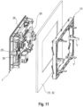
- Fig. 11
- dieselbe Vorrichtung zu Beginn der Montage an einer Montageöffnung eines Gerätes in einer Perspektivansicht schräg von hinten;
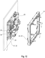
- Fig. 12
- dieselbe Vorrichtung nach dem Einsetzen des Modulträgers in die Montageöffnung und vor dem Verschnappen des Rastrahmen mit dem Modulträger in einer Perspektivansicht schräg von hinten;
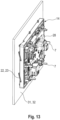
- Fig. 13
- dieselbe Vorrichtung mit verschnapptem Modulträger und Rastrahmen festgeklemmt an der Wand des Gehäuses in einer Perspektivansicht schräg von hinten.
- Gemäß
Fig. 1 weist ein Modulträger 1 einen rechteckigen, plattenförmigen Grundkörper 2 auf. Der Grundkörper 2 weist eine Platte 3 und von der Rückseite der Platte 3 vorstehende, ineinander kreuzende Rippen 4.1, 4.2 auf. Die Rippen 4.1, 4.2 weisen teilweise an den äußeren Enden nach hinten hakenförmig vorstehende Vorsprünge 5.1, 5.2 mit senkrecht zur Platte 3 ausgerichteten Außenkanten auf. - Der Grundkörper 2 weist am Außenumfang erste Schnappelemente 6 auf, die als senkrecht von der Grundplatte nach hinten vorstehende Schnapphaken 7 ausgebildet sind.
- Die Schnapphaken 7 weisen jeweils einen streifenförmigen Abschnitt 7.1 auf. In einem Abstand vom Grundkörper 2 steht vom streifenförmigen Abschnitt 7.1 nach außen ein Haken 7.2 in Form einer spitzwinklig zum streifenförmigen Abschnitt 7.1 geneigten Leiste vor. Der Haken 7.2 ist in einem Abstand vom hinteren Ende des streifenförmigen Abschnittes 7.1 angeordnet. Am hinteren Ende hat der streifenförmige Abschnitt 7.1 auf der Außenseite eine Anschrägung 7.3. Der Schnapphaken 7 bildet einen einarmigen Hebel mit einem kürzeren ersten Hebelarm 7.4 und einem längeren zweiten Hebelarm 7.5, der durch Drücken gegen die Außenseite des zweiten Hebelarms 7.5 geschwenkt werden kann.
- An den beiden langen Seiten des Grundkörpers 2 sind jeweils zwei Schnapphaken 7 und an den beiden kurzen Seiten des Grundkörpers 2 ist jeweils ein Schnapphaken 7 angeordnet.
- Von den seitlichen Rändern der Platte 3 des Grundkörpers 2 stehen senkrecht nach vorn leistenförmige Seitenwände 8.1-8.4 des Grundkörpers 2 vor, die eine Aussparung in Form einer Vertiefung 9 auf der Vorderseite des Grundkörpers 2 umgrenzen. Die Vertiefung 9 dient zum Einsetzen eines Moduls.
- An den vier Ecken der Platte 3 stehen nach hinten zwei diagonal angeordnete Schraubdome 10 und zwei ebenfalls diagonal angeordnete Positionsnasen 11 vor, die jeweils über eine seitliche Verrippung 12 an der Rückseite der Platte 3 abgestützt sind.
- An den Innenseiten der Schnapphaken weist der plattenförmige Grundkörper 3 aus fertigungstechnischen Gründen und zur Verbesserung der Elastizität der Schnapphaken rechteckige erste Durchbrüche 13 auf.
- Dem Modulträger 1 ist einstückig durch Spritzgießen hergestellt.
- Gemäß
Fig. 2 weist ein Rastrahmen 14 einen rechteckigen Rahmenkörper 15 mit vier Rahmenseiten 15.1-15.4 auf, die eine Rahmenöffnung 16 umgrenzen. Die Rahmenseiten 15.1-15.4 sind jeweils L-Profile 17.1-17.4. Erste Schenkel 18.1-18.4 der L-Profile 17.1-17.4 fallen in die Hauptebene (Ebene der größten Ausdehnung) des Rastrahmens 14 und bilden gemeinsam einen Anlageabschnitt 19 des Rastrahmens 14. Zweite Schenkel 20.1-20.4 des L-Profils 17.1-17 erstrecken sich vom Rand der Rahmenöffnung 16 aus vertikal zur Hauptebene des Rastrahmens 14 nach vorn und bilden gemeinsam einen Verbindungsabschnitt 21 des Rastrahmens 14. - Die Anlageabschnitt 19 weist auf der Vorderseite Federelemente 22 in Form von spitzwinklig zur Hauptebene geneigten Biegefedern 23 auf. An den beiden langen Rahmenseiten 15.1, 15.3 des Rastrahmens 14 sind jeweils drei Biegefedern 23 und an den beiden kurzen Rahmenseiten 15.2, 15.4 des Rastrahmens 14 sind jeweils zwei Biegefedern 23 angeordnet. Die Biegefedern 23 sind im Wesentlichen gleichmäßig über die Seiten des Anlageabschnitts 19 verteilt.
- Der Verbindungsabschnitt 21 weist am Innenumfang zweite Schnappelemente 24 in Form von Schnappaufnahmen auf. Die Schnappaufnahmen 25 sind am vorderen Rand des Verbindungsabschnitts 21 angeordnet. An den beiden langen Rahmenseiten 15.1, 15.3 sind jeweils zwei Schnappaufnahmen 25 und an den beiden kurzen Rahmenseiten 15.2, 15.4 ist jeweils nur eine Schnappaufnahme 25 angeordnet.
- Der Rastrahmen 14 ist einteilig aus Kunststoff spritzgegossen.
- Die Form und die Abmessungen des Modulträgers 1 und des Rastrahmens 14 sind so aufeinander abgestimmt, dass der Rastrahmen 14 mit seiner Rahmenöffnung 16 von hinten auf den Modulträger 1 aufschiebbar ist, sodass die Schnapphaken 7 in die Rahmenöffnung 16 und den Verbindungsabschnitt 21 eingreifen und mit den Schnappaufnahmen 25 verschnappen, indem sie mit den Haken 7.2 in die Schnappaufnahmen 25 eingreifen. In dieser Position weist die Vorderseite des Anlageabschnitts 19 des Rastrahmens 14 einen Abstand von der Vorderseite des Grundkörpers 2 auf, sodass dieser Abstandsbereich den Randbereich einer Montageöffnung einer Wand eines Gerätes aufnehmen kann.
- Die Vertiefung 9 des Modulträgers 1 dient dazu, ein Touchpanel oder ein anderes Modul aufzunehmen. Gemäß
Fig. 3 ist ein Modul 26 in die Vertiefung 9 eingesetzt, wobei das Modul 26 eine Stützplatte 27 beispielsweise in Form eines Displayglases aufweist, die in den Seiten des Grundkörpers 2 parallel zur Hauptebene (Ebene der größten Ausdehnung) des Grundkörpers 2 nach außen vorsteht. - Bei dem Ausführungsbeispiel von
Fig. 6 , das denselben Modulträger 1 wie inFig. 1 und einen vonFig. 2 abweichenden Rastrahmen 14 umfasst, ist das Modul 26 in der Vertiefung 9 gezeigt. - Das Modul 26 ist mittels einer Klebeverbindung an dem Modulträger 1 befestigt.
- Auf der Rückseite des Modulträgers 1 ist eine rechteckige Elektronikplatine 28 mit Löchern an den Ecken montierbar, wobei in zwei diagonal auf der Elektronikplatine 28 angeordnete Positionierungslöcher die Positionsnasen 11 eingeführt werden und durch die beiden diagonal angeordneten Schraublöcher hindurch Schrauben 29 eingesetzt und in die Schraubdome 10 eingeschraubt werden. Bei dem vorliegenden Ausführungsbeispiel ist dies weggelassen und in den
Fig. 11 bis 13 für ein anderes Ausführungsbeispiel gezeigt. - Gemäß
Fig. 3 werden zu Beginn der Montage Modulträger 1 und Rastrahmen 14 auf eine rechteckige Montageöffnung 30 in einer Wand 31 eines Gehäuses 32 eines Gerätes ausgerichtet. Bei der Wand 31 kann es sich um eine äußere Wand eines Gehäuses 32 handeln. Grundsätzlich kann es sich bei der Wand 31 auch um eine innere Wand eines Gerätes handeln, beispielsweise um eine Wand, die zwei Funktionsbereiche des Gerätes voneinander trennt. - Die Abmessungen der Montageöffnung 30 übersteigen geringfügig die Außenabmessungen des Grundkörpers 2.
- Gemäß
Fig. 4 wird in einem weiteren Montageschritt der Modulträger 1 mit dem Grundkörper 2 in die Montageöffnung 30 eingesetzt, bis sich die Stützplatte 27 auf der vorderen Seite der Wand 31 abstützt. - Schließlich wird der Rastrahmen 14 von hinten auf den Modulträger 1 aufgeschoben, bis sich die Federelemente 22 an der hinteren Seite der Wand 31 abstützen, etwas einfedern und die Schnapphaken 7 in die Schnappaufnahmen 25 einschnappen.
- In
Fig. 5 ist die Vorrichtung in der Einbaustellung gezeigt, in der der Modulträger 1 und der Rastrahmen 14 miteinander verschnappt sind und sich die Federelemente 22 elastisch verformt an der Wand 31 abstützen. In der Einbaustellung ist die aus Modulträger 1, Modul 26 und Rastrahmen 14 bestehende Vorrichtung 33 am äußeren Rand der Montageöffnung 30 an der Wand 31 festgeklemmt. Die Fertigungstoleranzen der Vorrichtung 33 und der Wand 31 werden durch die Federelemente 22 ausgeglichen. Auf eine genaue Abstimmung der Montageöffnung 30 und des Modulträgers 1 kommt es nicht an, da die Stützplatte 27 Spalte zwischen Montageöffnung 30 und Modulträger 1 außen abdeckt. - Die Montage der Vorrichtung 33 kann äußerst einfach und ohne Werkzeug durchgeführt werden. Auch ein Demontieren ist einfach und ohne Werkzeug möglich. Hierfür können die einander gegenüberliegenden Schnapphaken 7 des Modulträgers 1 an den hinteren Enden etwas zusammengedrückt werden, bis die Haken 7.2 aus den Schnappaufnahmen 25 freikommen. Danach kann der Rastrahmen 14 vom Modulträger 1 abgezogen und der Modulträger 1 aus der Montageöffnung 30 entnommen werden.
- Das Ausführungsbeispiel von
Fig. 6 bis 8 unterscheidet sich von dem Ausführungsbeispiel vonFig. 1 bis 5 dadurch, dass der Verbindungsabschnitt 21 des Rastrahmens 14 an mehreren hintereinander in senkrechter Richtung zum Anlageabschnitt 19 angeordneten Rastpositionen Schnappaufnahmen 25.1, 25.2, 25.3 aufweist. Infolgedessen sind der Modulträger 1 und der Rastrahmen 14 in verschiedenen Rastpositionen miteinander verschnappbar bzw. verrastbar. Dies ist vorteilhaft für einen groben Ausgleich von Fertigungstoleranzen und für die Verwendung der Vorrichtung 33 mit verschiedenen Geräten, bei denen die Montageöffnung 30 in Wänden 31 mit unterschiedlicher Wandstärke ausgebildet ist. - Die hinteren Ränder jeder Schnappaufnahme 25.1, 25.2, 25.3 sind entsprechend der Neigung der Hinterseite jedes Hakens 7.2 nach hinten geneigt, um das Verlagern des Rastrahmens 14 in eine nachfolgende Rastposition zu erleichtern.
- Zudem weist dieses Ausführungsbeispiel auf der vorderen Seite der Wand 31 eine um die Montageöffnung 30 herum verlaufende Außenstufe 34 auf, die so bemessen ist, dass sie die Stützplatte 27 aufnimmt. Infolgedessen schließt die Vorderseite der Stützplatte 27 bündig mit der vorderen Seite der Wand 31 neben der Außenstufe 34 ab. Der Spalt zwischen äußerem Umfang der Stützplatte 27 und der äußeren Begrenzung der Außenstufe kann kleingehalten werden. In der Ansicht von außen ist das Modul 26 perfekt in die Wand integriert.
- Das Ausführungsbeispiel von
Fig. 9 bis 13 unterscheidet sich von dem Ausführungsbeispiel vonFig. 1 bis 5 dadurch, dass die ersten Schnappelemente 6 des Modulträgers 1 als Schnappaufnahmen 25 und nicht als Schnapphaken ausgebildet sind und dass die zweiten Schnappelemente 24 des Rastrahmens als Schnapphaken 7 und nicht als Schnappaufnahmen ausgebildet sind. - Ein weiterer Unterschied besteht darin, dass die Stützplatte 27 einstückig mit dem Modulträger 1 und nicht mit dem Modul 26 ausgebildet ist.
- Der Modulträger 1 weist die Schnappaufnahmen 25 am Außenumfang der leistenförmigen Seitenwände 8.1-8.4 auf. Die Schnappaufnahmen 25 sind als rechteckige zweite Durchbrüche 35 des Modulträgers 1 ausgebildet. An den beiden langen Seiten des Grundkörpers 2 sind jeweils zwei Schnappaufnahmen 25 und an den beiden kurzen Seiten des Grundkörpers 2 ist jeweils eine Schnappaufnahme 25 angeordnet.
- Auf der Rückseite weist der Grundkörper 2 neben den Schnappaufnahmen 25 nach hinten vorstehende Einführschrägen 36 auf. Die Einführschrägen 36 sind an den Außenseiten von nach hinten vorstehenden parallelen Nocken 37.1, 37.2 ausgebildet, die durch einen Verbindungssteg miteinander verbunden sind.
- Die Stützplatte 27 ist ein rechteckiger Rahmen 38 mit einer Fensteröffnung 39 an der Vorderseite. Die Stützplatte 39 ist am Rand der Fensteröffnung 39 einstückig mit dem vorderen Rand der die Vertiefung 9 umgebenden leistenförmigen Seitenwände 8.1-8.4 verbunden und steht parallel zur Hauptebene des Grundkörpers 2 nach außen vor. Die Fensteröffnung 39 und die Vertiefung 9 bilden gemeinsam eine Aussparung 40 zum Einsetzen und Verkabeln eines Moduls 26.
- Der Grundkörper 2 kann Durchgangsöffnungen aufweisen, um mittels hindurchgeführter Kabel ein elektronisches Modul auf der Vorderseite des Grundkörpers mit einer Elektronikplatine auf der Rückseite des Grundkörpers oder mit einer Elektronik im Gerät zu verbinden.
- Der Modulträger 1 ist einteilig aus Kunststoff spritzgegossen.
- Gemäß
Fig. 10 weist der Rastrahmen am Innenumfang die Schnapphaken 7 auf. Jeder Schnapphaken 7 ist über eine Verbindungslasche 41 mit dem vorderen Rand des Verbindungsabschnitttes 21 verbunden. Jeder Schnapphaken 7 weist einen streifenförmigen Abschnitt 7.1 auf, der sich senkrecht zum Anlageabschnitt 19 erstreckt und am vorderen Ende einen nach innen vorstehenden Haken 7.2 aufweist. Die Verbindungslasche 41 ist mit der Mitte des streifenförmigen Abschnittes 7.1 verbunden. Somit ist der Schnapphaken 7 als zweiarmiger Hebel ausgebildet, mit einem ersten Hebelarm 7.4 vom Haken 7.2 bis zur Verbindungslasche 41 und einen zweiten Hebelarm 7.5 von der Verbindungslasche 41 bis zum hinteren Ende des streifenförmigen Abschnitts 7.1 der durch Betätigen des zweiten Hebelarms 7.5 geschwenkt werden kann. - Die Biegefedern 23 sind auf der Vorderseite des Rastrahmens 14 oberhalb von keilförmigen Einkerbungen 42 des Anlageabschnittes 19 angeordnet, sodass die Biegefedern 23 jeweils über der tiefsten Stelle der Einkerbung 42 an den Anlageabschnitt 19 angebunden sind. Diese Anordnung ist zur Erhöhung der Dauerfestigkeit und aus fertigungstechnischen Gründen gewählt.
- Der Rastrahmen 14 ist einteilig aus Kunststoff spritzgegossen.
- Auf der Vorderseite des Modulträgers 1 ist in die Aussparung 40 ein Modul eingeklebt, das in den Figuren nicht sichtbar ist. Auf der Rückseite des Modulträgers 1 ist gemäß
Fig. 11 bis 13 eine Elektronikplatine 28 fixiert. - Gemäß
Fig. 11 werden zu Beginn der Montage der Modulträger 1 und der Rastrahmen 14 auf verschiedenen Seiten der Montageöffnung 30 angeordnet und auf diese ausgerichtet. - Gemäß
Fig. 12 wird als nächstes der Modulträger 1 in die Montageöffnung 30 eingeschoben, bis die Stützplatte 27 an der vorderen Seite der Wand 31 anliegt. - Schließlich wird gemäß
Fig. 13 der Rastrahmen 14 von hinten auf den Modulträger 1 aufgeschoben, bis sich die Biegefedern 23 auf der hinteren Seite der Wand 31 abstützen, etwas einfedern und die Schnapphaken 7 in die Schnappaufnahmen 25 einschnappen. In der verschnappten Einbaustellung ist die Vorrichtung inFig. 13 gezeigt. - Auch bei dieser Ausführungsart kompensieren die Federelemente 22 Toleranzen der beteiligten Bauteile 1, 14, 31. Die Stützplatte 27 deckt den Randbereich der Montageöffnung 30 ab, sodass es nicht auf eine genaue Anpassung des Modulträgers 1 an die Montageöffnung 30 ankommt. Die Montage kann ohne Zuhilfenahme von Werkzeugen erfolgen. Auch eine Demontage ist leicht möglich, indem die hinteren Enden einander gegenüberliegender Schnapphaken 7 etwas zusammengeschwenkt werden. Sobald die Haken 7.2 aus den Schnappaufnahmen 25 freikommen, kann der Rastrahmen 14 vom Modulträger 1 abgezogen werden. Danach ist der Modulträger 1 aus der Montageöffnung 30 entnehmbar.
- Ein weiterer Vorteil ist, dass die Schnapphaken 7 Bestandteile des Rastrahmens 14 sind, sodass im Versagensfall der Rastrahmen 14 ersetzt werden muss. Der Rastrahmen 14 kann bevorzugt als Gleichteil für verschiedene Geräte verwendet werden, sodass ein Ersatz dieses Bauteils vergleichsweise kostengünstig möglich ist.
-
- 1
- Modulträger
- 2
- Grundkörper
- 3
- Platte
- 4.1,4.2
- Rippe
- 5.1, 5.2
- Vorsprung
- 6
- erstes Schnappelement
- 7
- Schnapphaken
- 7.1
- streifenförmiger Abschnitt
- 7.2
- Haken
- 7.3
- Anschrägung
- 7.4
- erster Hebelarm
- 7.5
- zweiter Hebelarm
- 8.1-8.4
- Seitenwand
- 9
- Vertiefung
- 10
- Schraubdom
- 11
- Positionsnase
- 12
- Verrippung
- 13
- erster Durchbruch
- 14
- Rastrahmen
- 15
- Rahmenkörper
- 15.1-15.4
- Rahmenseite
- 16
- Rahmenöffnung
- 17.1-17.4
- L-Profil
- 18.1-18.4
- erster Schenkel
- 19
- Anlageabschnitt
- 20.1-20.4
- zweiter Schenkel
- 21
- Verbindungsabschnitt
- 22
- Federelement
- 23
- Biegefeder
- 24
- zweites Schnappelement
- 25
- Schnappaufnahme
- 26
- Modul
- 27
- Stützplatte
- 28
- Elektronikplatine
- 29
- Schraube
- 30
- Montageöffnung
- 31
- Wand
- 32
- Gehäuse
- 33
- Vorrichtung
- 34
- Außenstufe
- 35
- zweiter Durchbruch
- 36
- Einführungsschräge
- 37.1,37.2
- Nocken
- 38
- Rahmen
- 39
- Fensteröffnung
- 40
- Aussparung
- 41
- Verbindungslasche
- 42
- Einkerbung
Claims (15)
- Vorrichtung zur mechanischen Befestigung eines Moduls an einer Wand eines Gerätes mit einer das Modul aufnehmenden Montageöffnung, umfassend:• einen Modulträger (1), der einen plattenförmigen Grundkörper (2) zum Einsetzen in die Montageöffnung (30) und mindestens ein erstes Schnappelement (6) am Außenumfang des Grundkörpers (2) aufweist,• ein Modul (26), das auf der Vorderseite des Grundkörpers (2) angeordnet und am Modulträger (1) befestigt ist,• eine Stützplatte (27) zum Abstützen auf einer vorderen Seite der Wand (31) mit der Montageöffnung (30), die mit dem Modulträger (1) oder Modul (26) verbunden ist und parallel zur Hauptebene des Grundkörpers (2) nach außen vorsteht,• einen Rastrahmen (14), der eine Rahmenöffnung (16) zum Einsetzen eines hinteren Teils des Grundkörpers (2) und mindestens ein zweites Schnappelement (24) am Innenumfang aufweist,• mindestens ein Federelement (22), das ausgebildet und angeordnet ist, den Rastrahmen (14) federnd auf der hinteren Seite der Wand (31) neben der Montageöffnung (30) abzustützen und/oder die Stützplatte (27) federnd auf der vorderen Seite der Wand abzustützen,• wobei das erste Schnappelement (6) und das zweite Schnappelement (24) ausgebildet sind, miteinander zu verschnappen, wenn der Grundkörper (2) in die Rahmenöffnung (16) eingesetzt ist, wobei zwischen der Rückseite der Stützplatte (27) und der Vorderseite des Rastrahmens (14) ein Abstand zur Aufnahme eines die Montageöffnung (30) umgebenden Randbereichs der Wand (31) vorhanden ist.
- Vorrichtung nach Anspruch 1, bei der die Stützplatte (27) einstückig mit dem Modulträger (1) oder mit dem Modul (26) verbunden ist.
- Vorrichtung nach Anspruch 1 oder 2, bei der der Modulträger (1) auf der Vorderseite eine Aussparung (40) aufweist und das Modul (26) in die Aussparung (40) eingesetzt ist.
- Vorrichtung nach einem der Ansprüche 1 bis 3, bei der das Modul (26) über eine Klebeverbindung mit dem Modulträger (1) verbunden ist.
- Vorrichtung nach einem der Ansprüche 1 bis 4, bei der das Modul (26) ein Display, ein Monitor, eine Tastatur, ein Touchscreen, ein anderes UI-Modul oder eine transparente Scheibe ist.
- Vorrichtung nach einem der Ansprüche 1 bis 5, bei der von der Rückseite des Grundkörpers (2) nach hinten Schraubdome (10) vorstehe und eine Elektronikplatine (28) mittels Schrauben (29) auf den Schaubdomen (10) befestigt ist.
- Vorrichtung nach einem der Ansprüche 1 bis 6, bei der der Modulträger (1) am Außenumfang mindestens einen nach hinten vorstehenden Schnapphaken (7) und der Rastrahmen (14) am Innenumfang mindestens eine Schnappaufnahme (25) für den Schnapphaken (7) aufweist und/oder bei der der Rastrahmen (14) am Innenumfang mindestens einen nach vorn vorstehenden Schnapphaken (7) und der Modulträger (1) am Außenumfang mindestens eine Schnappaufnahme (25) für den Schnapphaken (7) aufweist.
- Vorrichtung nach Anspruch 7, bei der der Schnapphaken (7) ein ein- oder zweiarmiger Hebel mit einem ersten Hebelarm (7.4) mit einem Haken (7.2) zum Einschnappen in eine Schnappaufnahme (25) und einem zweiten Hebelarm (7.3) zum Lösen der Schnappverbindung mit der Schnappaufnahme (25) ist.
- Vorrichtung nach einem der Ansprüche 1 bis 8, bei der der Modulträger (1) und/oder der Rastrahmen (14) an mehreren hintereinander in senkrechter Richtung zum plattenförmigen Grundkörper angeordneten Rastpositionen Schnappaufnahmen (25.1, 25.2, 25.3) aufweist.
- Vorrichtung nach einem der Ansprüche 1 bis 9, bei der der Modulträger (1) am Außenumfang mehrere erste Schnappelemente (6) aufweist und der Rastrahmen (14) am Innenumfang mehrere zweite Schnappelemente (24) aufweist.
- Vorrichtung nach einem der Ansprüche 1 bis 12, bei der das Federelement (22) von der Vorderseite des Rastrahmens (14) vorsteht.
- Vorrichtung nach einem der Ansprüche 1 bis 11, bei der der Rastrahmen (14) auf der Vorderseite mindestens ein als Biegefeder (23) ausgeführtes Federelement (22) aufweist, das spitzwinklig zur Rahmenebene geneigt ist.
- Vorrichtung nach einem der Ansprüche 1 bis 12, bei der der Schnapphaken (7) einstückig mit dem Modulträger (1) oder mit dem Rastrahmen (14) ausgebildet ist und/oder bei der die Schnappaufnahme einstückig mit dem Rastrahmen (14) oder dem Modulträger (1) ausgebildet ist und/oder bei der das Federelement (22) einstückig mit dem Rastrahmen (14) oder der Stützplatte (27) ausgebildet ist.
- Vorrichtung nach einem der Ansprüche 1 bis 13, bei der der Modulträger (1) aus einem Kunststoff und/oder der Rastrahmen (14) aus einem Kunststoff hergestellt ist.
- Vorrichtung nach einem der Ansprüche 1 bis 14, bei der der Modulträger (1) und/oder der Rastrahmen (14) spritzgegossen ist.
Priority Applications (3)
| Application Number | Priority Date | Filing Date | Title |
|---|---|---|---|
| EP23185285.6A EP4491886B1 (de) | 2023-07-13 | 2023-07-13 | Vorrichtung zur mechanischen befestigung eines moduls an einer wand eines gerätes mit einer das modul aufnehmenden montageöffnung |
| CN202410885034.7A CN119309102A (zh) | 2023-07-13 | 2024-07-03 | 将模块机械固定在设备的带有容纳模块的安装口的壁部上的装置 |
| US18/770,061 US20250020272A1 (en) | 2023-07-13 | 2024-07-11 | Device for mechanically fastening a module to a wall of a piece of equipment having a mounting opening that receives the module |
Applications Claiming Priority (1)
| Application Number | Priority Date | Filing Date | Title |
|---|---|---|---|
| EP23185285.6A EP4491886B1 (de) | 2023-07-13 | 2023-07-13 | Vorrichtung zur mechanischen befestigung eines moduls an einer wand eines gerätes mit einer das modul aufnehmenden montageöffnung |
Publications (2)
| Publication Number | Publication Date |
|---|---|
| EP4491886A1 true EP4491886A1 (de) | 2025-01-15 |
| EP4491886B1 EP4491886B1 (de) | 2025-11-19 |
Family
ID=87429353
Family Applications (1)
| Application Number | Title | Priority Date | Filing Date |
|---|---|---|---|
| EP23185285.6A Active EP4491886B1 (de) | 2023-07-13 | 2023-07-13 | Vorrichtung zur mechanischen befestigung eines moduls an einer wand eines gerätes mit einer das modul aufnehmenden montageöffnung |
Country Status (3)
| Country | Link |
|---|---|
| US (1) | US20250020272A1 (de) |
| EP (1) | EP4491886B1 (de) |
| CN (1) | CN119309102A (de) |
Families Citing this family (2)
| Publication number | Priority date | Publication date | Assignee | Title |
|---|---|---|---|---|
| DE102022108188A1 (de) * | 2022-04-05 | 2023-10-05 | Syntegon Technology Gmbh | Planar-Antriebssystem und ein Verfahren zur Montage und Demontage von Statormodulen |
| CN121205379A (zh) * | 2025-10-23 | 2025-12-26 | 上海建工四建集团有限公司 | 一种核心筒用企口模板和核心筒与楼承板连接节点的施工方法 |
Citations (3)
| Publication number | Priority date | Publication date | Assignee | Title |
|---|---|---|---|---|
| WO2010029042A1 (en) * | 2008-09-09 | 2010-03-18 | Arcelik Anonim Sirketi | A household appliance |
| CN108800734A (zh) | 2018-04-04 | 2018-11-13 | 青岛海尔股份有限公司 | 显示组件及具有该显示组件的冰箱 |
| DE102019203114A1 (de) * | 2019-03-07 | 2020-09-10 | BSH Hausgeräte GmbH | Haushaltskältegerät mit einer Anzeige- und/oder Bedieneinheit |
-
2023
- 2023-07-13 EP EP23185285.6A patent/EP4491886B1/de active Active
-
2024
- 2024-07-03 CN CN202410885034.7A patent/CN119309102A/zh active Pending
- 2024-07-11 US US18/770,061 patent/US20250020272A1/en active Pending
Patent Citations (3)
| Publication number | Priority date | Publication date | Assignee | Title |
|---|---|---|---|---|
| WO2010029042A1 (en) * | 2008-09-09 | 2010-03-18 | Arcelik Anonim Sirketi | A household appliance |
| CN108800734A (zh) | 2018-04-04 | 2018-11-13 | 青岛海尔股份有限公司 | 显示组件及具有该显示组件的冰箱 |
| DE102019203114A1 (de) * | 2019-03-07 | 2020-09-10 | BSH Hausgeräte GmbH | Haushaltskältegerät mit einer Anzeige- und/oder Bedieneinheit |
Also Published As
| Publication number | Publication date |
|---|---|
| US20250020272A1 (en) | 2025-01-16 |
| EP4491886B1 (de) | 2025-11-19 |
| CN119309102A (zh) | 2025-01-14 |
Similar Documents
| Publication | Publication Date | Title |
|---|---|---|
| EP4491886B1 (de) | Vorrichtung zur mechanischen befestigung eines moduls an einer wand eines gerätes mit einer das modul aufnehmenden montageöffnung | |
| EP1732375A2 (de) | Gerätelüfter | |
| DE102009052988A1 (de) | Türspiegel | |
| EP3257121B1 (de) | Anordnung mehrerer rastfüsse für eine baugruppe | |
| DE10004752A1 (de) | Instrumentengruppe und Sicherungsblock | |
| DE102007051716A1 (de) | Gehäuse für eine Kfz-Bedieneinheit | |
| DE10348979A1 (de) | Befestigung einer Leiterplatte an einem Gehäuse | |
| DE10227562B4 (de) | Abdeckrahmen für ein elektrisches Installationsgerät | |
| DE4111025A1 (de) | Vorrichtung zur befestigung von geraeten | |
| DE202018100278U1 (de) | Bedien-/Anzeigemodul für eine Spülmaschine | |
| DE10357799A1 (de) | Adaptersystem | |
| DE10055455C2 (de) | Anordnung zur schraubenlosen Festlegung von Komponenten | |
| EP0287703A1 (de) | Dichtung | |
| DE102007045462B4 (de) | I/O-Blech in einem Computergehäuse | |
| DE102024100111A1 (de) | Zähler- und Verteilerschrank | |
| EP1804065A1 (de) | Zählerplatz | |
| DE102019123764B4 (de) | Elektrisches Installationsgerät | |
| WO2018234075A1 (de) | Vorrichtung zum befestigen einer platte | |
| DE102009043656B4 (de) | I/O-Blende für ein Chassis eines Computersystems sowie Anordnung aus Chassis und I/O-Blende | |
| DE10203390B4 (de) | Einschubrahmen | |
| EP0545124B1 (de) | Einbaueinrichtung für Zusatzgeräte in vorgegebenen Einbauöffnungen von Kfz. | |
| EP4322716B1 (de) | Gehäuse für eine elektrische schaltung und zugehöriges herstellungsverfahren | |
| EP1575347B1 (de) | Federblech in einem Gehäuse als Abschirmung für ein elektronisches hochfrequenztechnisches Gerät | |
| DE102023121282A1 (de) | Elektronikmodul für ein Haushaltsgerät und Verfahren zur Herstellung eines Elektronikmoduls für ein Haushaltsgerät | |
| DE102022133156A1 (de) | Warmwasserspeicher |
Legal Events
| Date | Code | Title | Description |
|---|---|---|---|
| PUAI | Public reference made under article 153(3) epc to a published international application that has entered the european phase |
Free format text: ORIGINAL CODE: 0009012 |
|
| STAA | Information on the status of an ep patent application or granted ep patent |
Free format text: STATUS: THE APPLICATION HAS BEEN PUBLISHED |
|
| AK | Designated contracting states |
Kind code of ref document: A1 Designated state(s): AL AT BE BG CH CY CZ DE DK EE ES FI FR GB GR HR HU IE IS IT LI LT LU LV MC ME MK MT NL NO PL PT RO RS SE SI SK SM TR |
|
| STAA | Information on the status of an ep patent application or granted ep patent |
Free format text: STATUS: REQUEST FOR EXAMINATION WAS MADE |
|
| 17P | Request for examination filed |
Effective date: 20250409 |
|
| GRAP | Despatch of communication of intention to grant a patent |
Free format text: ORIGINAL CODE: EPIDOSNIGR1 |
|
| STAA | Information on the status of an ep patent application or granted ep patent |
Free format text: STATUS: GRANT OF PATENT IS INTENDED |
|
| INTG | Intention to grant announced |
Effective date: 20250613 |
|
| GRAS | Grant fee paid |
Free format text: ORIGINAL CODE: EPIDOSNIGR3 |
|
| GRAA | (expected) grant |
Free format text: ORIGINAL CODE: 0009210 |
|
| STAA | Information on the status of an ep patent application or granted ep patent |
Free format text: STATUS: THE PATENT HAS BEEN GRANTED |
|
| AK | Designated contracting states |
Kind code of ref document: B1 Designated state(s): AL AT BE BG CH CY CZ DE DK EE ES FI FR GB GR HR HU IE IS IT LI LT LU LV MC ME MK MT NL NO PL PT RO RS SE SI SK SM TR |
|
| REG | Reference to a national code |
Ref country code: CH Ref legal event code: F10 Free format text: ST27 STATUS EVENT CODE: U-0-0-F10-F00 (AS PROVIDED BY THE NATIONAL OFFICE) Effective date: 20251119 Ref country code: GB Ref legal event code: FG4D Free format text: NOT ENGLISH |
|
| P01 | Opt-out of the competence of the unified patent court (upc) registered |
Free format text: CASE NUMBER: UPC_APP_0012293_4491886/2025 Effective date: 20251105 |
|
| REG | Reference to a national code |
Ref country code: DE Ref legal event code: R096 Ref document number: 502023002239 Country of ref document: DE |
|
| REG | Reference to a national code |
Ref country code: IE Ref legal event code: FG4D Free format text: LANGUAGE OF EP DOCUMENT: GERMAN |
|
| REG | Reference to a national code |
Ref country code: NL Ref legal event code: MP Effective date: 20251119 |
|
| PG25 | Lapsed in a contracting state [announced via postgrant information from national office to epo] |
Ref country code: ES Free format text: LAPSE BECAUSE OF FAILURE TO SUBMIT A TRANSLATION OF THE DESCRIPTION OR TO PAY THE FEE WITHIN THE PRESCRIBED TIME-LIMIT Effective date: 20251119 |
|
| REG | Reference to a national code |
Ref country code: LT Ref legal event code: MG9D |
|
| PG25 | Lapsed in a contracting state [announced via postgrant information from national office to epo] |
Ref country code: NO Free format text: LAPSE BECAUSE OF FAILURE TO SUBMIT A TRANSLATION OF THE DESCRIPTION OR TO PAY THE FEE WITHIN THE PRESCRIBED TIME-LIMIT Effective date: 20260219 |
|
| PG25 | Lapsed in a contracting state [announced via postgrant information from national office to epo] |
Ref country code: HR Free format text: LAPSE BECAUSE OF FAILURE TO SUBMIT A TRANSLATION OF THE DESCRIPTION OR TO PAY THE FEE WITHIN THE PRESCRIBED TIME-LIMIT Effective date: 20251119 Ref country code: FI Free format text: LAPSE BECAUSE OF FAILURE TO SUBMIT A TRANSLATION OF THE DESCRIPTION OR TO PAY THE FEE WITHIN THE PRESCRIBED TIME-LIMIT Effective date: 20251119 |
|
| PG25 | Lapsed in a contracting state [announced via postgrant information from national office to epo] |
Ref country code: NL Free format text: LAPSE BECAUSE OF FAILURE TO SUBMIT A TRANSLATION OF THE DESCRIPTION OR TO PAY THE FEE WITHIN THE PRESCRIBED TIME-LIMIT Effective date: 20251119 |
|
| PG25 | Lapsed in a contracting state [announced via postgrant information from national office to epo] |
Ref country code: RS Free format text: LAPSE BECAUSE OF FAILURE TO SUBMIT A TRANSLATION OF THE DESCRIPTION OR TO PAY THE FEE WITHIN THE PRESCRIBED TIME-LIMIT Effective date: 20260219 |
|
| PG25 | Lapsed in a contracting state [announced via postgrant information from national office to epo] |
Ref country code: IS Free format text: LAPSE BECAUSE OF FAILURE TO SUBMIT A TRANSLATION OF THE DESCRIPTION OR TO PAY THE FEE WITHIN THE PRESCRIBED TIME-LIMIT Effective date: 20260319 |
|
| PG25 | Lapsed in a contracting state [announced via postgrant information from national office to epo] |
Ref country code: PT Free format text: LAPSE BECAUSE OF FAILURE TO SUBMIT A TRANSLATION OF THE DESCRIPTION OR TO PAY THE FEE WITHIN THE PRESCRIBED TIME-LIMIT Effective date: 20260319 |
|
| PG25 | Lapsed in a contracting state [announced via postgrant information from national office to epo] |
Ref country code: PL Free format text: LAPSE BECAUSE OF FAILURE TO SUBMIT A TRANSLATION OF THE DESCRIPTION OR TO PAY THE FEE WITHIN THE PRESCRIBED TIME-LIMIT Effective date: 20251119 |
|
| PG25 | Lapsed in a contracting state [announced via postgrant information from national office to epo] |
Ref country code: LV Free format text: LAPSE BECAUSE OF FAILURE TO SUBMIT A TRANSLATION OF THE DESCRIPTION OR TO PAY THE FEE WITHIN THE PRESCRIBED TIME-LIMIT Effective date: 20251119 |
|
| PG25 | Lapsed in a contracting state [announced via postgrant information from national office to epo] |
Ref country code: BG Free format text: LAPSE BECAUSE OF FAILURE TO SUBMIT A TRANSLATION OF THE DESCRIPTION OR TO PAY THE FEE WITHIN THE PRESCRIBED TIME-LIMIT Effective date: 20251119 |
|
| PG25 | Lapsed in a contracting state [announced via postgrant information from national office to epo] |
Ref country code: LT Free format text: LAPSE BECAUSE OF FAILURE TO SUBMIT A TRANSLATION OF THE DESCRIPTION OR TO PAY THE FEE WITHIN THE PRESCRIBED TIME-LIMIT Effective date: 20251119 |
|
| PG25 | Lapsed in a contracting state [announced via postgrant information from national office to epo] |
Ref country code: SM Free format text: LAPSE BECAUSE OF FAILURE TO SUBMIT A TRANSLATION OF THE DESCRIPTION OR TO PAY THE FEE WITHIN THE PRESCRIBED TIME-LIMIT Effective date: 20251119 |
|
| PG25 | Lapsed in a contracting state [announced via postgrant information from national office to epo] |
Ref country code: DK Free format text: LAPSE BECAUSE OF FAILURE TO SUBMIT A TRANSLATION OF THE DESCRIPTION OR TO PAY THE FEE WITHIN THE PRESCRIBED TIME-LIMIT Effective date: 20251119 |
|
| PG25 | Lapsed in a contracting state [announced via postgrant information from national office to epo] |
Ref country code: IT Free format text: LAPSE BECAUSE OF FAILURE TO SUBMIT A TRANSLATION OF THE DESCRIPTION OR TO PAY THE FEE WITHIN THE PRESCRIBED TIME-LIMIT Effective date: 20251119 |
|
| PG25 | Lapsed in a contracting state [announced via postgrant information from national office to epo] |
Ref country code: EE Free format text: LAPSE BECAUSE OF FAILURE TO SUBMIT A TRANSLATION OF THE DESCRIPTION OR TO PAY THE FEE WITHIN THE PRESCRIBED TIME-LIMIT Effective date: 20251119 |
|
| PG25 | Lapsed in a contracting state [announced via postgrant information from national office to epo] |
Ref country code: CZ Free format text: LAPSE BECAUSE OF FAILURE TO SUBMIT A TRANSLATION OF THE DESCRIPTION OR TO PAY THE FEE WITHIN THE PRESCRIBED TIME-LIMIT Effective date: 20251119 |
|
| PG25 | Lapsed in a contracting state [announced via postgrant information from national office to epo] |
Ref country code: SK Free format text: LAPSE BECAUSE OF FAILURE TO SUBMIT A TRANSLATION OF THE DESCRIPTION OR TO PAY THE FEE WITHIN THE PRESCRIBED TIME-LIMIT Effective date: 20251119 |
|
| PG25 | Lapsed in a contracting state [announced via postgrant information from national office to epo] |
Ref country code: SE Free format text: LAPSE BECAUSE OF FAILURE TO SUBMIT A TRANSLATION OF THE DESCRIPTION OR TO PAY THE FEE WITHIN THE PRESCRIBED TIME-LIMIT Effective date: 20251119 |