EP4491084A1 - Basisstation zur wartung eines kehrroboters - Google Patents
Basisstation zur wartung eines kehrroboters Download PDFInfo
- Publication number
- EP4491084A1 EP4491084A1 EP23765707.7A EP23765707A EP4491084A1 EP 4491084 A1 EP4491084 A1 EP 4491084A1 EP 23765707 A EP23765707 A EP 23765707A EP 4491084 A1 EP4491084 A1 EP 4491084A1
- Authority
- EP
- European Patent Office
- Prior art keywords
- tray body
- execution
- base station
- vacuum cleaner
- module
- Prior art date
- Legal status (The legal status is an assumption and is not a legal conclusion. Google has not performed a legal analysis and makes no representation as to the accuracy of the status listed.)
- Pending
Links
Images



Classifications
-
- A—HUMAN NECESSITIES
- A47—FURNITURE; DOMESTIC ARTICLES OR APPLIANCES; COFFEE MILLS; SPICE MILLS; SUCTION CLEANERS IN GENERAL
- A47L—DOMESTIC WASHING OR CLEANING; SUCTION CLEANERS IN GENERAL
- A47L11/00—Machines for cleaning floors, carpets, furniture, walls, or wall coverings
- A47L11/28—Floor-scrubbing machines, motor-driven
- A47L11/282—Floor-scrubbing machines, motor-driven having rotary tools
-
- A—HUMAN NECESSITIES
- A47—FURNITURE; DOMESTIC ARTICLES OR APPLIANCES; COFFEE MILLS; SPICE MILLS; SUCTION CLEANERS IN GENERAL
- A47L—DOMESTIC WASHING OR CLEANING; SUCTION CLEANERS IN GENERAL
- A47L11/00—Machines for cleaning floors, carpets, furniture, walls, or wall coverings
- A47L11/40—Parts or details of machines not provided for in groups A47L11/02 - A47L11/38, or not restricted to one of these groups, e.g. handles, arrangements of switches, skirts, buffers, levers
- A47L11/4091—Storing or parking devices, arrangements therefor; Means allowing transport of the machine when it is not being used
-
- A—HUMAN NECESSITIES
- A47—FURNITURE; DOMESTIC ARTICLES OR APPLIANCES; COFFEE MILLS; SPICE MILLS; SUCTION CLEANERS IN GENERAL
- A47L—DOMESTIC WASHING OR CLEANING; SUCTION CLEANERS IN GENERAL
- A47L2201/00—Robotic cleaning machines, i.e. with automatic control of the travelling movement or the cleaning operation
- A47L2201/02—Docking stations; Docking operations
- A47L2201/028—Refurbishing floor engaging tools, e.g. cleaning of beating brushes
Definitions
- the present application relates to the field of robot cleaner, and in particular, to a base station for maintaining a robot vacuum cleaner.
- Robot vacuum cleaners may perform floor cleaning tasks, where the robot vacuum cleaner may, on a basis of the configuration of hardware modules, selectively implement the dust removal and cleaning function, or the wiping cleaning function of wiping the floor by using a wiping medium such as a rag, or the combined functions of dust removal and wiping cleaning.
- a wiping medium such as a rag
- the dust removal and cleaning function may be considered as the basic function of the robot vacuum cleaner, which may be implemented based on the built-in cleaning module of the robot vacuum cleaner; and the wiping and cleaning function may be considered as an additional function of the robot vacuum cleaner, which may be implemented based on the wiping module detachably installed on the robot vacuum cleaner.
- a robot vacuum cleaner that needs to be configured with a wiping cleaning function, it may have the need to detach and install the wiping module.
- Embodiments of the present application provide a base station for maintaining a robot vacuum cleaner, which can implement automatic detachment and installation of a wiping module of the robot vacuum cleaner.
- a base station for maintaining a robot vacuum cleaner including: a base station base; a maintenance tray including an execution tray body; a coupling mechanism arranged on the execution tray body; a lift mechanism that provides an adjustable support for the maintenance tray, and the adjustable support is used to enable a translational ascent and descent of the execution tray body along a first direction between a first height position and a second height position; where the second height position is adjacent to a bottom installation position of a wiping module on a robot vacuum cleaner, and the first height position is lower than the second height position.
- the robot vacuum cleaner generates a continuous coupling force used to attract the wiping module at the bottom installation position, and the coupling mechanism is used to generate, for the wiping module, a controllable coupling force greater than the continuous coupling force, so as to implement automatic detachment and installation of the wiping module on the robot vacuum cleaner (70) based on coordination between the controllable coupling force / continuous coupling force and the translational ascent and descent of the execution tray body.
- the execution tray body when the robot vacuum cleaner installed with the wiping module is docked at the base station base, the execution tray body is driven by the lift mechanism to ascend from the first height position to the second height position, when the execution tray body reaches the second height position, the coupling mechanism contacts the wiping module and generates the controllable coupling force; after the coupling mechanism generates the controllable coupling force, the execution tray body is driven by the lift mechanism to descend from the second height position to the first height position, and the coupling mechanism continues generating the controllable coupling force while descending along with the execution tray body, so as to enable the wiping module to overcome the continuous coupling force generated by the robot vacuum cleaner and descend along with the execution tray body, thereby implementing automatic detachment of the wiping module from the robot vacuum cleaner.
- a wiping module to be installed is placed on the execution tray body, and the coupling mechanism starts to generate the controllable coupling force;
- the execution tray body is driven by the lift mechanism to ascend from the first height position to the second height position, and the coupling mechanism generates the controllable coupling force while ascending along with the execution tray body, so as to keep the wiping module stably supported on the execution tray body;
- the execution tray body reaches the second height position, the wiping module reaches the bottom installation position of the robot vacuum cleaner, and the coupling mechanism stops generating the controllable coupling force, so as to enable the wiping module to be detachably installed at the bottom installation position of the robot vacuum cleaner under a constraint of the continuous coupling force generated by the robot vacuum cleaner, thus implementing automatic installation of the wiping module on the robot vacuum cleaner; and after the coupling mechanism stops generating the controllable coupling force, the execution tray body is driven by the
- a wiping module to be installed is placed on the execution tray body, when the robot vacuum cleaner for which the wiping module is to be installed with is docked at the base station base, the execution tray body is driven by the lift mechanism to ascend from the first height position to the second height position, and the coupling mechanism does not generate the controllable coupling force while ascending along with the execution tray body, when the execution tray body reaches the second height position, the wiping module reaches the bottom installation position of the robot vacuum cleaner, so as to enable the wiping module to be detachably installed at the bottom installation position of the robot vacuum cleaner under a constraint of the continuous coupling force generated by the robot vacuum cleaner, thus implementing automatic installation of the wiping module on the robot vacuum cleaner; and the execution tray body is driven by the lift mechanism to descend from the second height position to the first height position, and the coupling mechanism still does not generate the controllable coupling force while descending along with the execution tray body.
- the robot vacuum cleaner is installed with a host coupling assembly
- the wiping module includes a module coupling assembly
- the continuous coupling force includes a permanent magnetic attraction force generated between the host coupling assembly and the module coupling assembly.
- the coupling mechanism includes an electromagnetic component
- the controllable coupling force includes an electromagnetic attraction force generated between the electromagnetic component and the module coupling assembly, and the electromagnetic attraction force is greater than the permanent magnetic attraction force.
- the host coupling assembly includes a first iron member; the module coupling assembly includes a permanent magnetic member and a second iron member; where the wiping module includes a medium support.
- the permanent magnetic member is arranged on a side of the medium support facing the robot vacuum cleaner, and the second iron member is arranged on other side of the medium support facing the maintenance tray.
- the permanent magnetic attraction force is generated between the permanent magnetic member and the first iron member, and the electromagnetic attraction force is generated between the electromagnetic component and the second iron member.
- the base station further includes an electric drive module, and the electric drive module is electrically connected to the lift mechanism and the electromagnetic component, so as to cooperatively control the lifting/lowering drive of the lift mechanism and controllable power-on of the electromagnetic component.
- the medium support is capable of being driven to rotate by the robot vacuum cleaner, and the medium support is used to install a wiping medium.
- the host coupling assembly, the module coupling assembly, and the coupling mechanism are all arranged in alignment with a rotation axis of the medium support.
- the robot vacuum cleaner includes a drive module used to drive the medium support to rotate; where the host coupling assembly is installed on an output shaft of the drive module.
- the medium support has a rotating shaft sleeve on a side facing the robot vacuum cleaner, and the rotating shaft sleeve is used to be inserted into a plug-in shaft cavity at a bottom of the robot vacuum cleaner, so as to be coaxially connected to the output shaft of the drive module in the plug-in shaft cavity, and the permanent magnetic member of the module coupling assembly is arranged inside the rotating shaft sleeve.
- the maintenance tray further includes a hollow cylinder connected to the execution tray body; and the coupling mechanism is fixedly installed in the hollow cylinder.
- the hollow cylinder sinks and extends on a bottom surface side of the execution tray body.
- the base station base includes a base main shell used to dock the robot vacuum cleaner, where an interior of the base main shell forms a base inner cavity, and the base main shell has a tray opening exposing the base inner cavity.
- the execution tray body is suspended and supported by the lift mechanism at the tray opening; and the base station base further includes a guide cylinder arranged in the base inner cavity; where the hollow cylinder is slidably plugged in the guide cylinder along the first direction, so as to constrain the translational ascent and descent of the execution tray body in the first direction.
- the maintenance tray further includes a hollow cylinder connected to the execution tray body; and the coupling mechanism is fixedly installed in the hollow cylinder.
- the host coupling assembly, the module coupling assembly, and the hollow cylinder accommodating the coupling mechanism are all arranged in alignment with the rotation axis of the medium support.
- the medium support has a positioning groove surrounding the module coupling assembly; and the hollow cylinder has an opening flange protruding from a top surface side of the execution tray body.
- the opening flange is used to form a plug-in fit capable of rotating and sliding against each other with the positioning groove.
- the lift mechanism includes a power module, a transmission mechanism, and a swing member.
- the power module is used to generate a driving force; and the transmission mechanism is used to apply the driving force generated by the power module to the swing member, so as to drive the translational ascent and descent of the execution tray body through a swing of the swing member in response to the driving force.
- the swing member has a fulcrum rotation shaft, and a first end and a second end that are respectively located on opposite sides of the fulcrum rotation shaft; where the fulcrum rotation shaft is in rotational fit with a rotation shaft support of the base station base, so that the swing of the swing member in response to the driving force is constrained as a swing with the fulcrum rotation shaft as a fixed fulcrum; where the driving force is applied, by the transmission mechanism, to the first end along a second direction, and there is a preset angle difference between the first direction and the second direction; a first slip fit is formed between the first end and the transmission mechanism, and a second slip fit is formed between the second end and the execution tray body, and the first slip fit and the second slip fit are used to eliminate fitting interference between the swing member and the transmission mechanism as well as the execution tray body due to the angle difference.
- the transmission mechanism includes a guide member arranged along the second direction, and a moving assembly movably installed on the guide member; where the moving assembly has a transmission sliding groove, and the first end and the transmission sliding groove form the first slip fit; and, an extension direction of the transmission sliding groove is arranged to enable the first slip fit to: obtain an input force effective on the first end from resolution of the driving force, and an application direction of the input force on the first end is a tangential direction at the fixed fulcrum.
- the maintenance tray further includes a tray sliding groove located on the execution tray body; where the second end and the tray sliding groove form the second slip fit; where an extension direction of the tray sliding groove is arranged to enable the second slip fit to: obtain an output force effective on the execution tray body from resolution of the input force applied on the first end, and an application direction of the output force through the tray sliding groove on the execution tray body is the first direction.
- the maintenance tray further includes a flexible skirt surrounding a periphery of the execution tray body; where the flexible skirt is fixed to an opening edge of the tray opening, and the flexible skirt undergoes stretching and contracting deformation in response to the translational ascent and descent of the execution tray body.
- the base station base further includes a stop buckle arranged in the base inner cavity; and the maintenance tray further includes a vertical buckle formed on the execution tray body; where the vertical buckle downwardly extends toward the base inner cavity, and when the execution tray body is located at the second height position, the vertical buckle is in interference fit with the stop buckle, so as to prevent the execution tray body from excessively ascending beyond the second height position.
- the maintenance tray further includes a laterally protruding lug arranged on the execution tray body; where the laterally protruding lug extends laterally from a lower edge of the flexible skirt, and when the execution tray body is located at the second height position, the laterally protruding lug engages with the opening edge of the tray opening by interference, so as to prevent the execution tray body from excessively ascending beyond the second height position.
- the maintenance tray of the base station has an execution tray body for performing maintenance operations on the docked robot vacuum cleaner, where the execution tray body can perform translational ascent and descent between the first height position and the second height position based on the adjustable support of the lift mechanism, and the execution tray body may be arranged with a coupling mechanism.
- the coupling mechanism may generate a controllable coupling force, and the controllable coupling force is greater than the continuous coupling force of the robot vacuum cleaner to constrain the wiping module at the bottom, based on the controllable coupling force generated by the coupling mechanism and the coordination between the lifting/lowering adjustment of the lift mechanism on the execution tray body where the coupling mechanism is located, automatic detachment and installation of a wiping module at the bottom of the robot vacuum cleaner may be implemented.
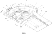
- FIG. 1 is a principle diagram of automatic detachment or installation of a wiping module implemented by a base station for maintaining a robot vacuum cleaner according to an embodiment of the present application.
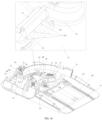
- FIG. 2 is a structure diagram showing arrangement of a coupling mechanism of the base station in the embodiment as illustrated in FIG. 1 .
- the base station for maintaining a robot vacuum cleaner may include a base station base 10, where the base station base 10 may be used to dock a robot vacuum cleaner to be maintained.
- the base station base 10 may be built in with a wireless communication module and a wired or wireless charging mechanism, so that the robot vacuum cleaner can pair with the base station based on the communication module while being docked on the base station base 10, and the base station can perform charging and maintenance based on the charging mechanism after the pairing is successful.
- arrangement, installation structure, and configuration selection of the charging mechanism in the base station are not focused on, so in the graphic expression and text description of the charging mechanism will be omitted in the drawings and the text description below.
- the base station in one or more embodiments of the present application, in order to enable the base station for maintaining a robot vacuum cleaner to perform other maintenance operations in addition to charging, the base station may further include a maintenance tray 20.
- the base station base 10 may include a base main shell 12. An interior of the base main shell 12 may form a base inner cavity 100, and the base main shell 12 may have a tray opening 122 exposing the base inner cavity 100. The maintenance tray 20 may be deployed above the tray opening 122.
- the base station base 10 may further include a protective baffle 13, which is provided as a semicircular arc-shaped bending part surrounding the tray opening 122 and used to protect the robot vacuum cleaner and prevent the robot vacuum cleaner from falling off from a highest point of the base station base when the robot vacuum cleaner is docked on the base station base 10.
- the maintenance tray 20 may include an execution tray body 21, and the execution tray body 21 may be used to perform maintenance operations on the robot vacuum cleaner 70 docked on the base station base 10.
- the execution tray body 21 may be deployed with one or more operating mechanisms used to perform maintenance operations.
- the operating mechanism deployed on the execution tray body 21 may include a coupling mechanism 90, where the coupling mechanism 90 may be used to implement automatic detachment or installation of the wiping module for the robot vacuum cleaner.
- the base station for maintaining the robot vacuum cleaner may further include a lift mechanism 30, which may provide adjustable support for the maintenance tray 20.
- the adjustable support is used to enable a translational ascent/descent of the execution tray body 21 along a first direction D1 between a first height position and a second height position.
- the second height position is adjacent to a bottom installation position of the wiping module 80 on the robot vacuum cleaner, and the first height position is lower than the second height position.
- the first height position may be a position where the execution tray body 21 is flush or substantially flush with the tray opening 122.
- the first height position may be understood as the non-contact position between the execution tray body 21 and the robot vacuum cleaner.
- the execution tray body 21 is adjusted to the first height position by the lift mechanism 30 to avoid interference and collision between the execution tray body 21 and the robot vacuum cleaner.
- the second height position may be understood as the contact position between the execution tray body 21 and the robot vacuum cleaner.
- the base station for maintaining the robot vacuum cleaner in an embodiment of the present application may further include a detection mechanism used to detect a motion state of the robot vacuum cleaner and a positional relationship of the robot vacuum cleaner relative to the base station base 10.
- the specific implementation of the detection mechanism is not a focus of the embodiments of the present application, and therefore is not described in detail here.
- the robot vacuum cleaner 70 may generate a continuous coupling force for attracting the wiping module 80 at the bottom installation position for installing the wiping module 80.
- the robot vacuum cleaner 70 may be installed with a host coupling component 71
- the wiping module 80 may include a module coupling component 81
- the continuous coupling force generated by the robot vacuum cleaner 70 at the bottom installation position may include a permanent magnetic attraction force generated between the host coupling component 71 and the module coupling component 81.
- the coupling mechanism 90 may be used to generate a controllable coupling force greater than the continuous coupling force, so as to implement the detachment or installation of the wiping module 80 in the robot vacuum cleaner 70 based on the coordination of the controllable coupling force and the translational ascent/descent of the execution tray body 21.
- the coupling mechanism 90 may include an electromagnetic component
- the controllable coupling force controllably generated by the coupling mechanism 90 may include: an electromagnetic attraction force controllably generated between the electromagnetic component of the coupling mechanism 90 and the module coupling assembly 81 of the wiping module 80, and the electromagnetic attraction force may be greater than the permanent magnetic attraction force between the host coupling assembly 71 of the robot vacuum cleaner 70 and the module coupling assembly 81 of the wiping module 80.
- the electric drive module electrically connected to the lift mechanism 30 in the base station for maintaining the robot vacuum cleaner may further be electrically connected to the coupling mechanism 90 to coordinately control the lifting/lowering drive of the lift mechanism 30 and the controllable power-on of the electromagnetic component of the coupling mechanism 90, thereby implementing the coordination of the controllable coupling force and the translational ascent/descent of the execution tray body 21.
- the maintenance tray 20 of the base station has the execution tray body 21 used to perform maintenance operations on the docked robot vacuum cleaner, where the lift mechanism 30 provides adjustable support for the execution tray body 21, so that the execution tray body 21 may be enabled to perform a translational ascent/descent between the first height position and the second height position.
- the second height position of the execution tray body 21 may be adjacent to the bottom installation position of the wiping module on the robot vacuum cleaner.
- the coupling mechanism 90 may generate a controllable coupling force, and the controllable coupling force may be greater than the continuous coupling force of the robot vacuum cleaner 70 to constrain the wiping module 80 at the bottom, therefore, based on the coordination between the controllable coupling force generated by the coupling mechanism 90 / the continuous coupling force and the lifting/lowering adjustment of the execution tray body 21 where the coupling mechanism 90 is located by the lift mechanism 30, the automatic detachment or installation of the wiping module 80 at the bottom of the robot vacuum cleaner 70 may be implemented.
- FIG. 3 is a state diagram of a base station in the embodiment as illustrated in FIG. 1 during contact detachment or installation operation of a wiping module by using a coupling mechanism.
- FIG. 4 is a diagram showing placement state of a wiping module separated from the robot vacuum cleaner and placed at the base station in the embodiment as illustrated in FIG. 1 .
- the coordination between the controllable coupling force generated by the coupling mechanism 90 and the lifting/lowering adjustment of the execution tray body 21 where the coupling mechanism 90 is located by the lift mechanism 30 may implement automatic detachment process as illustrated in a sequence from FIG. 3 to FIG. 4 and automatic installation process as illustrated in a sequence from FIG. 4 to FIG. 3 .
- the wiping module 80 may include a medium support 82 that may be driven to rotate by the robot vacuum cleaner 70.
- the medium support 82 is used to install a wiping medium 800, e.g., a rag.
- the wiping medium may be installed on the side of the medium support 82 away from the robot vacuum cleaner 70 (i.e., the side of the medium support 82 facing the maintenance tray 20), and the host coupling assembly 71, the module coupling assembly 81, and the coupling mechanism 90 may all be arranged in alignment with the rotation axis of the medium support 82.
- the host coupling assembly 71 may include a first iron member; the module coupling assembly 81 may include a permanent magnetic member 81a and a second iron member 81b, where the permanent magnetic member 81a may be arranged on the side of the medium support 82 facing the robot vacuum cleaner 70, and the second iron member 81b is arranged on the other side of the medium support 82 facing the maintenance tray 20.
- the permanent magnetic attraction force between the host coupling assembly 71 and the module coupling assembly 81 may be generated between the permanent magnetic member 81a of the module coupling assembly 81 and the first iron member of host coupling assembly 71; and the electromagnetic attraction force between the coupling mechanism 90 and the module coupling assembly 81 may be generated between the electromagnetic component of the coupling mechanism 90 and the second iron member 81b of the module coupling assembly 81.
- FIG. 5 is an exploded structure diagram of the base station in the embodiment as illustrated in FIG. 1 .
- FIG. 6 is a working principle diagram of a lift mechanism of the base station in the embodiment as illustrated in FIG. 1 .
- the lift mechanism 30 may include a power module 31, a transmission mechanism 32, and a swing member 33.
- the lift mechanism 30 may further include an installation bottom box 34, and the power module 31 may be accommodated in the installation bottom box 34.
- the installation bottom box 34 is used to perform shock absorption for the power module 31, and may be made of materials such as rubber.
- the power module 31 may include a power element such as a motor, and the power module 31 is used to generate a driving force.
- the transmission mechanism 32 is used to apply the driving force generated by the power module 31 to the swing member 33, so as to drive the translational ascent/descent of the execution tray body 21 through a swing of the swing member 33 in response to the driving force.
- the power module 31 and the transmission mechanism 32 may be located outside the base inner cavity 100 of the base station base 10, and the swing member 33 may extend into the base inner cavity 100 of the base station base 10 and provide at the tray opening 122 the adjustable support for the execution tray body 21.
- the maintenance tray 20 of the base station has an execution tray body 21 used to perform maintenance operations on the docked robot vacuum cleaner, where the lift mechanism 30 may provide adjustable support for the execution tray body 21 by using the swing of the swing member 33, so that the execution tray body 21 may be enabled to perform a translational ascent/descent between the first height position and the second height position; and the second height position of the execution tray body 21 may be adjacent to the bottom installation position of the wiping module on the robot vacuum cleaner. Therefore, based on the lifting/lowering adjustment of the execution tray body 21 by the lift mechanism 30, contact maintenance operations may be performed on the wiping module at the bottom of the robot vacuum cleaner by means of the operating mechanism deployed on the execution tray body 21.
- the switching of the execution tray body 21 of the maintenance tray 20 between the first height position and the second height position is in the first direction D1
- the transmission mechanism 32 may apply the driving force generated by the power module 31 to the swing member 33 in the second direction different from the first direction D1, i.e., there may be a direction deviation between the lifting/lowering direction of the execution tray body 21 (i.e., the first direction D1) and the transmission direction of the transmission mechanism 32 (i.e., the second direction D2), and the direction deviation may be represented as a preset angle difference/deviation between the first direction D 1 and the second direction D2.
- the base main shell 12 of the base station base 10 may have a bottom surface arranged in the horizontal direction, and the bottom surface may be provided with a base bottom plate 11 located below the base inner cavity 100.
- the base main shell 12 of the base station base 10 may also have a docking slope 121 inclined relative to the horizontal plane (i.e., the base bottom plate 11 or the bottom surface of the base station base 10), and the docking slope 121 may be used to dock the robot vacuum cleaner.
- the docking slope 121 is raised upward where it is close to the maintenance tray 20 (i.e., the tray opening 122) on the side, and the raised height may be determined according to the space height that the part of swing member 33 near the second end 332 needs to occupy in the bottom inner cavity 100.
- the surface of the inclined docking slope 121 may be provided with anti-slip particles 126.
- the first direction D1 in which the execution tray body 21 undergoes lifting/lowering switching between the first height position and the second height position may be an inclined direction perpendicular to the docking slope 121; and the second direction D2 in which the transmission mechanism 32 applies a driving force to the swing member 33 may be a vertical direction perpendicular to the horizontal plane (i.e., the base bottom plate 11 or the bottom surface of the base station base 10).
- FIG. 7 is a principle structure diagram of a lift mechanism of the base station in the embodiment as illustrated in FIG. 1 used to adapt to a direction deviation.
- the swing member 33 may adopt a lever type structure with a slip fit allowance at both ends.
- the swing member 33 may have a fulcrum rotation shaft 330, and a first end 331 and a second end 332 respectively located on opposite sides of the fulcrum rotation shaft 330.
- the fulcrum rotation shaft 330 of the swing member 33 is in rotational fit with a rotation shaft support 123 of the base station base 10, so that the swing of the swing member 33 in response to the driving force is constrained to swing with the fulcrum rotation shaft 330 as a fixed fulcrum.
- the driving force generated by the power module 31 may be applied, by the transmission mechanism 32, along the second direction D2 to the first end 331 of the swing member 33.
- a first slip fit is formed between the first end 331 of the swing member 33 and the transmission mechanism 32, for example, the first end 331 of the swing member 33 may form the first slip fit with the transmission mechanism 32 outside the base inner cavity 100 of the base station base 10.
- a second slip fit is formed between the second end 332 of the swing member 33 and the execution tray body 21 of the maintenance tray 20, for example, the second end 332 of the swing member 33 may extend into the base inner cavity 100 of the base station base 10, and the second end 332 of the swing member 33 may form the second slip fit with the execution tray body 21 at the tray opening 122.
- first slip fit and the second slip fit are used to eliminate fitting interference between the swing member 33 and the transmission mechanism 32 as well as the execution tray body 21 due to the angle difference between the first direction D1 and the second direction D2.
- the transmission mechanism 32 of the lift mechanism 30 may include a guide member 321 arranged along the second direction D2, and a moving assembly 322 movably installed on the guide member 321, where the moving assembly 322 may move along the guide member 321 in the second direction D2 in response to the driving force generated by the power module 31, so as to apply the driving force along the second direction D2 to the first end 331 of the swing member 33.
- the moving assembly 322 has a transmission sliding groove 323, and the first end 331 of the swing member 33 may form the above-mentioned first slip fit with the transmission sliding groove 323, for example, the first end 331 may have a first guide column protruding laterally, which is slidably inserted into the transmission sliding groove 323, and may form the first slip fit between the first end 331 of the swing member 33 and the transmission sliding groove 323.
- An extension direction of the transmission sliding groove 323 of the moving assembly 322 is approximately at an acute angle to the horizontal plane, and by means of this extension direction, the first slip fit between the first end 331 and the transmission sliding groove 323 can, obtain an input force effective on the swing member 33 / the first end 331 from resolution of the driving force generated by the power module 31, and the applying direction of the input force on the first end 331 of the swing member 33 is a tangential direction at the fulcrum rotation shaft 330.
- the power module 31 may include a stepping motor
- the guide member 321 may include a screw coaxially connected to an output shaft of the stepping motor of the power module 31
- the moving assembly 322 may include a nut flange 322a and a moving body 322b, where the nut flange 322a may mesh with the screw of the guide member 321.
- the nut flange 322a may also be fixedly connected to the moving body 322b, and the transmission sliding groove 323 may be formed in the moving body 322b.
- the first end 331 of the swing member 33 not only forms a first slip fit by using slidable insertion of the first guide column thereof at the transmission sliding groove 323, but also forms an anti-rotation backing with the moving body 322b.
- the anti-rotation backing is configured to form an anti-rotation constraint to prevent the moving body 322b from rotating in the direction around the screw.
- the first end 331 of the swing member 33 adopts a double-arm structure to clamp the moving body 322b on opposite sides of the moving body 322b.
- the nut flange 322a fixedly connected to the moving body 322b is also subject to the above-mentioned anti-rotation constraint, i.e., the moving body 322b forming the first slip fit with the swing member 33 (i.e., the first end 331) may exert a anti-rotation constraint for the nut flange 322a.
- the nut flange 322a meshed with the screw may, due to the anti-rotation constraint, in response to the meshing transmission with the rotating screw, be linearly lifted/lowered along the second direction D2, and then drive the moving body 322b fixedly connected thereto to be linearly lifted/lowered along the second direction D2, so as to apply the driving force generated by the power module 31 along the second direction D2 to the first end 331 of the swing member 33 forming the first slip fit with the transmission sliding groove. Furthermore, by switching rotation of the output shaft of the stepping motor of the power module 31 forward and reverse, the ascent/descent switching may be implemented.
- the maintenance tray 20 may further include a tray sliding groove 25 located on the execution tray body 21, and the second end 332 of the swing member 33 may form the second slip fit with the tray sliding groove 25.
- the second end 332 of the swing member 33 may have the second guide column protruding laterally, and the second guide column is slidably inserted into the tray sliding groove 25, so as to form the second slip fit between the second end 332 of the swing member 33 and the tray sliding groove 25.
- An extension direction of the tray sliding groove 25 is approximately at an acute angle to the horizontal plane, and by means of this extension direction, the second slip fit between the second end 332 of the swing member 33 and the tray sliding groove 25 can, obtain an output force effective on the execution tray body 21 from resolution of the above-mentioned input force applied on the first end 331, and the direction of the output force through the tray sliding groove 25 on the execution tray body 21 is the first direction D1.
- the swing member 33 may be arched, with a top of the arch facing downward, and the fulcrum rotation shaft 330 for forming the fixed fulcrum may be located at the top of the arch.
- the embodiments of the present application may also assist the maintenance tray 20 in guiding and position limiting, so as to further optimize the lifting/lowering stability and reliability of the execution tray body 21 of the maintenance tray 20.
- the lift mechanism 30 may further include position detection components, which may be arranged at the limit positions of movement of the moving assembly 322 along the guide member 321, so that when the moving assembly 322 moves to a preset limit position along the guide member 321, a driving signal may be generated for causing the motor of the power module 31 to stop rotating.
- the limit positions of movement of the moving component 322 along the guide member 321 may be determined according to the first height position and the second height position.
- FIG. 8 is a schematic diagram showing the assembly relationship between the maintenance tray and the base station base in the base station in the embodiment as illustrated in FIG. 1 .
- FIG. 9 is a structure diagram showing limiting of the position of the maintenance tray by using a base station base in the base station in the embodiment as illustrated in FIG. 1 .
- the base station base 10 has a base inner cavity 100 formed inside the base main shell 12
- the base main shell 12 has a tray opening 122 exposing the base inner cavity 100
- the maintenance tray 20 is arranged at the tray opening 122:
- the base station base 10 may further include one or more guide cylinders 111 arranged in the base inner cavity 100, for example, the one or more guide cylinders 111 may be formed on the base bottom plate 11.
- the base bottom plate 11 may cover a bottom opening 120 in the base main shell 12 below the base inner cavity 100, so that the one or more guide cylinders 111 protrude toward the tray opening 122 along the first direction D 1.
- the maintenance tray 20 may further include one or more hollow cylinders 22 connected to the execution tray body 21.
- the one or more hollow cylinders 22 may sink and extend on a side of the execution tray body 21 facing the base inner cavity 100, so that the hollow cylinders 22 may be slidably plugged in with the one or more guide cylinders 111 respectively along the first direction D1, so as to constrain the translational ascent/descent of the execution tray body 21 to realize switch between the first height position and the second height position in the first direction D1 .
- the execution tray body 21 of the maintenance tray 20 may be flush or substantially flush with the tray opening 122 when at the first height position, and when the execution tray body 21 is at the second height position higher than the first height position, a gap is formed between the execution tray body 21 and the tray opening 122.
- the coupling mechanism 90 may be fixedly installed in the hollow cylinder 22. Since the hollow cylinder 22 may sink and extend on the bottom side of the execution tray body 21 toward the base inner cavity 100, so as to facilitate the sliding plug-in with the guide cylinder 111, installing the coupling mechanism 90 in the hollow cylinder 22 may also prevent the coupling mechanism 90 contained therein from interfering with the wiping module 80.
- the wiping module 80 includes a medium support 82 that may be driven to rotate by the robot vacuum cleaner 70, and the host coupling assembly 71, the module coupling assembly 81, and the coupling mechanism 90 may all be arranged in alignment with the rotation axis of the medium support 82, then the docking position of the robot vacuum cleaner 70 on the base station base 10 may be positioned to enable the output shaft of the drive module 72 of the robot vacuum cleaner 70 to be coaxially aligned with the hollow cylinder 22 along the first direction D 1.
- the medium support 82 may have a positioning groove 83, which is arranged to surround the rotation axis.
- the positioning groove 83 may be arranged to surround the module coupling assembly 81 (e.g., the second iron member 81b) which is at the rotation axis.
- the hollow cylinder 22 may have an opening flange 220 protruding on the top surface side of the execution tray body 21 away from the base inner cavity 100. The opening flange 220 is used to form a plug-in fit allowing rotating and sliding relative to each other with the positioning groove, so that the rotation axis of the medium support 82 can be positioned coaxially with the output shaft of the drive module 72 of the robot vacuum cleaner 70.
- the maintenance tray 20 may further include a flexible skirt 26 surrounding a periphery of the execution tray body 21.
- the flexible skirt 26 is fixed to an opening edge of the tray opening 122, for example, an upper edge of the flexible skirt 26 is connected to the execution tray body 21, and a lower edge of the flexible skirt 26 may form a skirt flange 27. Moreover, the skirt flange 27 may be fixed to the opening edge of the tray opening 122 by riveting or screw connection. In an embodiment, the flexible skirt 26 may form a waterproof seal for the tray opening 122 by covering the tray opening 122.
- the flexible skirt 26 may undergo stretching/contracting deformation in response to the translational ascent/descent between the first height position and the second height position, for example, the flexible skirt 26 may be in a pleated folded shape when the execution tray body 21 is at the first height position, and the flexible skirt 26 may be in a stretched state when the execution tray body 21 is at the second height position.
- the embodiments of the present application may also arrange a position-limiting constraint between the base station base 10 and the execution tray body 21 of the maintenance tray 20.
- the position-limiting constraint is used to constrain an upward limit position of the execution tray body 21, to avoid excessive ascent of the execution tray body 21 when the position detection component of the lift mechanism 30 fails; and a downward limit position of the execution tray body 21 may be set to a physical limit position of the transmission mechanism 32 of the lift mechanism 30 in the direction of driving the execution tray body 21 to descend, or, the downward limit position of the execution tray body 21 may be constrained by size interference between the execution tray body 21 and the tray opening 122.
- the maintenance tray 20 may further include one or more laterally protruding lugs 24 installed on the execution tray body 21, and the laterally protruding lugs 24 extend laterally from the lower edge of the flexible skirt 26;
- the execution tray body 21, the one or more hollow cylinders 22, the vertical buckle 23, the tray sliding groove 25, the flexible skirt 26, and the skirt flange 27 included in the maintenance tray 20 may be integrally formed by injection molding, while the one or more laterally protruding lugs 24 may be an independent rigid member.
- the execution tray body 21, the one or more hollow cylinders 22, the vertical buckle 23, the tray sliding groove 25, the flexible skirt 26, and the skirt flange 27 may all have flexibility of injection molding materials, where the flexibility of the flexible skirt 26 means that the flexible skirt 26 has a more easily deformable flexibility than other integrally formed parts of the maintenance tray 20, and is not intended to limit other integrally formed parts of the maintenance tray 20 to be rigid.
- the operating mechanism deployed on the execution tray body 21 may include not only the coupling mechanism 90 but also a cleaning mechanism 50, where the cleaning mechanism 50 may be used to clean the wiping module installed on the robot vacuum cleaner.
- FIG. 10 is a deployment structure diagram of a cleaning mechanism in the embodiment as illustrated in FIG. 1 .
- the base station for maintaining the robot vacuum cleaner may further include a cleaning mechanism 50 used as an operating mechanism.
- the cleaning mechanism 50 may be arranged on the execution tray body 21 of the maintenance tray 20, and is used to perform contact cleaning of the wiping module installed on the robot vacuum cleaner.
- the arrangement position of the cleaning mechanism 50 on the execution tray body 21 may be located outside the contact area where the lift mechanism 30 provides adjustable support to the execution tray body 21, so as to provide floating support for the cleaning mechanism 50 by utilizing the elastic deformation allowance of the execution tray body 21 itself.
- the cleaning mechanism 50 may include a spraying member 51 and a flow guiding member 52.
- the spraying member 51 is used to spray fluid, where, when the robot vacuum cleaner installed with the wiping module is docked on the base station base 10 and the execution tray body 21 is lifted to the second height position, the execution tray body 21 may contact the wiping module (e.g., contact a wiping medium such as a rag installed on the wiping module), and the fluid sprayed by the spraying member 51 is sprayed from the spraying member 51 at an angle that avoids the wiping module (i.e., the wiping medium), i.e., the spraying member 51 is used to spray fluid at an angle avoiding the wiping module when the execution tray body 21 is at the second height position.
- the wiping medium such as a rag installed on the wiping module
- the spraying member 51 may include a member body 511 protruding from a top surface of the execution tray body 21, and one or more jet outlets 512 on the side wall of the member body 511, so that the fluid ejected laterally from the one or more jet outlets 512 may avoid the wiping module.
- the one or more jet outlets 512 may be opened at the bottom of the side wall of the member body 511 close to the execution tray body 21.
- the member body 511 may be a hollow rib integrally formed on the execution tray body 21, so that the fluid may be introduced into the hollow rib from a fluid supply pipeline below the execution tray body, and ejected from the one or more jet outlets 512 opened on the rib wall of the hollow rib.
- the flow guiding member 52 is used to guide the fluid ejected by the spraying member 51 at an angle avoiding the wiping module to diffuse toward the wiping module (wiping medium).
- the flow guiding member 52 may be arranged separate from the spraying member 51, where space between the flow guiding member 52 and the spraying member 51 may allow the fluid to hit the flow guiding member 52 after being ejected from the spraying member 51.
- the fluid may hit the flow guiding member 52 with a preset intensity after being ejected from the spraying member 51, and the flow guiding member 52 may splash and diffuse the impacted fluid to the surface area of the wiping module exposed at the space.
- the fluid after the fluid hits the flow guiding member 52, it may be uniformly diffused and ejected to the surface area of the wiping module exposed at the space.
- the flow guiding member 52 may be a plate-shaped retaining rib integrally formed on the execution tray body 21, and the plate-shaped retaining rib may have an inclined rib wall facing the spraying member 51, so as to utilize the inclined rib wall to uniformly diffuse and eject the impacted fluid to the wiping module.
- the cleaning mechanism 50 arranged on the execution tray body 21 may perform contact automatic cleaning on the wiping module installed on the robot vacuum cleaner without affecting the fluid injection when the execution tray body 21 contacts the wiping module.
- the cleaning mechanism adopts a flow supply method in which the fluid ejected by the spraying member 51 is uniformly guided to the wiping module through the flow guiding member 52, which helps to improve the uniformity of cleaning to the wiping module.
- the wiping module 80 includes a medium support 82 that may be driven to rotate by the robot vacuum cleaner 70
- the member body 511 of the spraying member 1 and the flow guiding member 52 may both extend radially from the aligned position of the execution tray body 21 with the rotation axis of the medium support 82, and the side wall of the member body 511 may be arranged with a plurality of jet outlets 512 in the direction of the radial extension.
- the cleaning mechanism 50 may further include a scraping member 53.
- the scraping member 53 may include a boss base 531 and a plurality of raised bumps 532 distributed on a top surface of the boss base 531.
- the scraping member 53 may have interference friction with the wiping medium 800 installed on the medium support 82.
- the scraping member 53 may also extend radially from the aligned position of the execution tray body 21 with the rotation axis of the execution tray body 21, and the scraping member 53 may have a phase interval/gap with respect to the spraying member 51 and the flow guiding member 52 in the rotation direction of the medium support 82.
- the base station base 10 may also have a drainage mechanism 124 and sewage discharge member 125, where the drainage mechanism 124 forms a drainage path for a dirt flow overflowing from the wiping module to flow from the maintenance tray 20 to the sewage discharge member 125.
- the sewage discharge member 125 may be detachably installed on the base main shell 12, and the drainage mechanism 124 may be a diversion slope formed on the outer periphery of the maintenance tray 20, which may guide the dirt flow overflowing from the wiping module to flow naturally toward the sewage discharge member 125.
- the base station for maintaining the robot vacuum cleaner in embodiments of the present application may support the robot vacuum cleaner to flexibly switch between different working modes, for example, sweeping-only mode, mopping-only mode, and combined mode.
- the sweeping-only mode means that the robot vacuum cleaner 70 only uses a built-in cleaning assembly 73 to perform the dust removal task of sweeping floating dust on the ground, without an installation of a wiping module 80 for wiping the ground.
- the mopping-only mode means that the robot vacuum cleaner 70 uses the installed wiping module 80 to perform the mopping task of wiping the floor, and the cleaning assembly 73 stops running during this period.
- the combined mode means that the robot vacuum cleaner 70 uses the installed wiping module 80 to perform the mopping task of wiping the floor, and the cleaning assembly 73 continues running during this period.
- the switching between the sweeping-only mode and any of mopping-only mode and combined mode may be implemented by automatic detachment or installation of the wiping module 80 by using the coupling mechanism 90.
- the robot vacuum cleaner 70 may use the cleaning mechanism 50 to wet the wiping medium 800 of the wiping module 80; after completing the mopping task, the robot vacuum cleaner 70 may use the cleaning mechanism 50 to clean the wiping medium 800 of the wiping module 80.
- automatic detachment and installation may also be performed by means of the coupling mechanism 90, to install the wiping module 80 with a clean wiping medium 800 for the robot vacuum cleaner 70.
Landscapes
- Nozzles For Electric Vacuum Cleaners (AREA)
- Manipulator (AREA)
Applications Claiming Priority (3)
| Application Number | Priority Date | Filing Date | Title |
|---|---|---|---|
| CN202210224166.6A CN114468897B (zh) | 2022-03-09 | 2022-03-09 | 用于维护扫地机器人的基站 |
| CN202220498771.8U CN218922425U (zh) | 2022-03-09 | 2022-03-09 | 用于维护扫地机器人的基站 |
| PCT/CN2023/075129 WO2023169129A1 (zh) | 2022-03-09 | 2023-02-09 | 用于维护扫地机器人的基站 |
Publications (2)
| Publication Number | Publication Date |
|---|---|
| EP4491084A1 true EP4491084A1 (de) | 2025-01-15 |
| EP4491084A4 EP4491084A4 (de) | 2025-10-15 |
Family
ID=87937113
Family Applications (1)
| Application Number | Title | Priority Date | Filing Date |
|---|---|---|---|
| EP23765707.7A Pending EP4491084A4 (de) | 2022-03-09 | 2023-02-09 | Basisstation zur wartung eines kehrroboters |
Country Status (2)
| Country | Link |
|---|---|
| EP (1) | EP4491084A4 (de) |
| WO (1) | WO2023169129A1 (de) |
Family Cites Families (9)
| Publication number | Priority date | Publication date | Assignee | Title |
|---|---|---|---|---|
| KR102103420B1 (ko) * | 2013-12-30 | 2020-05-29 | 삼성전자주식회사 | 패드 교체 장치, 이를 포함하는 청소기 및 청소기 시스템 |
| JP2021526446A (ja) * | 2018-06-08 | 2021-10-07 | ポジテック パワー ツールズ(スーチョウ)カンパニー,リミティド | 掃除ロボット及びその制御方法、掃除ロボットシステム |
| KR102575206B1 (ko) * | 2018-11-06 | 2023-09-07 | 삼성전자주식회사 | 로봇 청소기, 스테이션 및 청소 시스템 |
| CN112741561B (zh) * | 2020-12-30 | 2025-02-28 | 深圳拓邦股份有限公司 | 一种基座、扫地机器人清洁系统及其工作方法 |
| CN215502788U (zh) * | 2021-01-29 | 2022-01-14 | 深圳拓邦股份有限公司 | 一种扫地机抹布板的拆装机构、扫地机基站以及系统 |
| CN215959640U (zh) * | 2021-10-08 | 2022-03-08 | 广东立霖智能科技有限公司 | 一种自动更换清洗抹布的基站机构 |
| CN114468897B (zh) * | 2022-03-09 | 2025-12-12 | 杭州萤石软件有限公司 | 用于维护扫地机器人的基站 |
| CN114424913B (zh) * | 2022-03-09 | 2025-12-12 | 杭州萤石软件有限公司 | 用于维护扫地机器人的基站 |
| CN114431777B (zh) * | 2022-03-09 | 2025-11-14 | 杭州萤石软件有限公司 | 用于维护扫地机器人的基站 |
-
2023
- 2023-02-09 EP EP23765707.7A patent/EP4491084A4/de active Pending
- 2023-02-09 WO PCT/CN2023/075129 patent/WO2023169129A1/zh not_active Ceased
Also Published As
| Publication number | Publication date |
|---|---|
| EP4491084A4 (de) | 2025-10-15 |
| WO2023169129A1 (zh) | 2023-09-14 |
Similar Documents
| Publication | Publication Date | Title |
|---|---|---|
| CN114424913B (zh) | 用于维护扫地机器人的基站 | |
| CN114431777B (zh) | 用于维护扫地机器人的基站 | |
| CN114468897B (zh) | 用于维护扫地机器人的基站 | |
| CN216962364U (zh) | 用于维护扫地机器人的基站 | |
| CN216962324U (zh) | 用于维护扫地机器人的基站 | |
| KR102440144B1 (ko) | 로봇청소기, 그 제어방법, 및 로봇청소기 시스템 | |
| CN221903485U (zh) | 清洁设备 | |
| CN110035836A (zh) | 用于输送粘性材料的设备 | |
| JP2025501210A (ja) | 自浄式メンテナンスステーションおよび自浄式システム | |
| JP2025501211A (ja) | 自浄式メンテナンスステーションおよび自浄式システム | |
| CN218922425U (zh) | 用于维护扫地机器人的基站 | |
| CN116269065B (zh) | 清洁系统、清洁基站及抹布盘拆卸方法 | |
| CN112323906B (zh) | 一种清洁机器人用工作站 | |
| KR101870561B1 (ko) | 건물 외벽 유리창용 자동 청소장치 | |
| CN114587202B (zh) | 一种升降装置以及清洁设备 | |
| CN210842864U (zh) | 一种扫地机器人 | |
| CN116548875A (zh) | 一种可升降盘刷组件及清洁装置 | |
| WO2023169129A1 (zh) | 用于维护扫地机器人的基站 | |
| KR100575668B1 (ko) | 로봇 청소기의 충전장치 | |
| CN113467199A (zh) | 一种便于拆卸的防止反溅液体污染晶圆的装置 | |
| WO2023169137A1 (zh) | 用于维护扫地机器人的基站 | |
| WO2023169138A1 (zh) | 用于维护扫地机器人的基站 | |
| EP4721638A1 (de) | Reinigungsanordnung für reinigungsvorrichtung und reinigungsvorrichtung | |
| CN217244178U (zh) | 清洁基站及清洁装置 | |
| CN221493420U (zh) | 清洁装置及油烟机 |
Legal Events
| Date | Code | Title | Description |
|---|---|---|---|
| STAA | Information on the status of an ep patent application or granted ep patent |
Free format text: STATUS: THE INTERNATIONAL PUBLICATION HAS BEEN MADE |
|
| PUAI | Public reference made under article 153(3) epc to a published international application that has entered the european phase |
Free format text: ORIGINAL CODE: 0009012 |
|
| STAA | Information on the status of an ep patent application or granted ep patent |
Free format text: STATUS: REQUEST FOR EXAMINATION WAS MADE |
|
| 17P | Request for examination filed |
Effective date: 20241007 |
|
| AK | Designated contracting states |
Kind code of ref document: A1 Designated state(s): AL AT BE BG CH CY CZ DE DK EE ES FI FR GB GR HR HU IE IS IT LI LT LU LV MC ME MK MT NL NO PL PT RO RS SE SI SK SM TR |
|
| DAV | Request for validation of the european patent (deleted) | ||
| DAX | Request for extension of the european patent (deleted) | ||
| RIC1 | Information provided on ipc code assigned before grant |
Ipc: A47L 11/40 20060101AFI20250616BHEP Ipc: A47L 11/24 20060101ALI20250616BHEP Ipc: A47L 11/282 20060101ALI20250616BHEP |
|
| A4 | Supplementary search report drawn up and despatched |
Effective date: 20250916 |
|
| RIC1 | Information provided on ipc code assigned before grant |
Ipc: A47L 11/40 20060101AFI20250910BHEP Ipc: A47L 11/24 20060101ALI20250910BHEP Ipc: A47L 11/282 20060101ALI20250910BHEP |