EP4489158A2 - Verfahren zur herstellung einer elektrodenanordnung für eine sekundärbatterie mit wasserfreiem elektrolyt, elektrodenanordnung und batterie - Google Patents
Verfahren zur herstellung einer elektrodenanordnung für eine sekundärbatterie mit wasserfreiem elektrolyt, elektrodenanordnung und batterie Download PDFInfo
- Publication number
- EP4489158A2 EP4489158A2 EP24177882.8A EP24177882A EP4489158A2 EP 4489158 A2 EP4489158 A2 EP 4489158A2 EP 24177882 A EP24177882 A EP 24177882A EP 4489158 A2 EP4489158 A2 EP 4489158A2
- Authority
- EP
- European Patent Office
- Prior art keywords
- separator
- electrode plate
- aqueous electrolyte
- positive electrode
- electrode assembly
- Prior art date
- Legal status (The legal status is an assumption and is not a legal conclusion. Google has not performed a legal analysis and makes no representation as to the accuracy of the status listed.)
- Pending
Links
Images


Classifications
-
- H—ELECTRICITY
- H01—ELECTRIC ELEMENTS
- H01M—PROCESSES OR MEANS, e.g. BATTERIES, FOR THE DIRECT CONVERSION OF CHEMICAL ENERGY INTO ELECTRICAL ENERGY
- H01M10/00—Secondary cells; Manufacture thereof
- H01M10/04—Construction or manufacture in general
- H01M10/0431—Cells with wound or folded electrodes
-
- H—ELECTRICITY
- H01—ELECTRIC ELEMENTS
- H01M—PROCESSES OR MEANS, e.g. BATTERIES, FOR THE DIRECT CONVERSION OF CHEMICAL ENERGY INTO ELECTRICAL ENERGY
- H01M10/00—Secondary cells; Manufacture thereof
- H01M10/05—Accumulators with non-aqueous electrolyte
- H01M10/058—Construction or manufacture
- H01M10/0585—Construction or manufacture of accumulators having only flat construction elements, i.e. flat positive electrodes, flat negative electrodes and flat separators
-
- H—ELECTRICITY
- H01—ELECTRIC ELEMENTS
- H01M—PROCESSES OR MEANS, e.g. BATTERIES, FOR THE DIRECT CONVERSION OF CHEMICAL ENERGY INTO ELECTRICAL ENERGY
- H01M10/00—Secondary cells; Manufacture thereof
- H01M10/04—Construction or manufacture in general
- H01M10/0468—Compression means for stacks of electrodes and separators
-
- H—ELECTRICITY
- H01—ELECTRIC ELEMENTS
- H01M—PROCESSES OR MEANS, e.g. BATTERIES, FOR THE DIRECT CONVERSION OF CHEMICAL ENERGY INTO ELECTRICAL ENERGY
- H01M10/00—Secondary cells; Manufacture thereof
- H01M10/04—Construction or manufacture in general
- H01M10/0481—Compression means other than compression means for stacks of electrodes and separators
-
- H—ELECTRICITY
- H01—ELECTRIC ELEMENTS
- H01M—PROCESSES OR MEANS, e.g. BATTERIES, FOR THE DIRECT CONVERSION OF CHEMICAL ENERGY INTO ELECTRICAL ENERGY
- H01M10/00—Secondary cells; Manufacture thereof
- H01M10/05—Accumulators with non-aqueous electrolyte
-
- H—ELECTRICITY
- H01—ELECTRIC ELEMENTS
- H01M—PROCESSES OR MEANS, e.g. BATTERIES, FOR THE DIRECT CONVERSION OF CHEMICAL ENERGY INTO ELECTRICAL ENERGY
- H01M10/00—Secondary cells; Manufacture thereof
- H01M10/05—Accumulators with non-aqueous electrolyte
- H01M10/052—Li-accumulators
- H01M10/0525—Rocking-chair batteries, i.e. batteries with lithium insertion or intercalation in both electrodes; Lithium-ion batteries
-
- H—ELECTRICITY
- H01—ELECTRIC ELEMENTS
- H01M—PROCESSES OR MEANS, e.g. BATTERIES, FOR THE DIRECT CONVERSION OF CHEMICAL ENERGY INTO ELECTRICAL ENERGY
- H01M10/00—Secondary cells; Manufacture thereof
- H01M10/05—Accumulators with non-aqueous electrolyte
- H01M10/058—Construction or manufacture
- H01M10/0587—Construction or manufacture of accumulators having only wound construction elements, i.e. wound positive electrodes, wound negative electrodes and wound separators
-
- H—ELECTRICITY
- H01—ELECTRIC ELEMENTS
- H01M—PROCESSES OR MEANS, e.g. BATTERIES, FOR THE DIRECT CONVERSION OF CHEMICAL ENERGY INTO ELECTRICAL ENERGY
- H01M50/00—Constructional details or processes of manufacture of the non-active parts of electrochemical cells other than fuel cells, e.g. hybrid cells
- H01M50/40—Separators; Membranes; Diaphragms; Spacing elements inside cells
- H01M50/409—Separators, membranes or diaphragms characterised by the material
- H01M50/449—Separators, membranes or diaphragms characterised by the material having a layered structure
-
- H—ELECTRICITY
- H01—ELECTRIC ELEMENTS
- H01M—PROCESSES OR MEANS, e.g. BATTERIES, FOR THE DIRECT CONVERSION OF CHEMICAL ENERGY INTO ELECTRICAL ENERGY
- H01M50/00—Constructional details or processes of manufacture of the non-active parts of electrochemical cells other than fuel cells, e.g. hybrid cells
- H01M50/40—Separators; Membranes; Diaphragms; Spacing elements inside cells
- H01M50/46—Separators, membranes or diaphragms characterised by their combination with electrodes
- H01M50/461—Separators, membranes or diaphragms characterised by their combination with electrodes with adhesive layers between electrodes and separators
-
- H—ELECTRICITY
- H01—ELECTRIC ELEMENTS
- H01M—PROCESSES OR MEANS, e.g. BATTERIES, FOR THE DIRECT CONVERSION OF CHEMICAL ENERGY INTO ELECTRICAL ENERGY
- H01M50/00—Constructional details or processes of manufacture of the non-active parts of electrochemical cells other than fuel cells, e.g. hybrid cells
- H01M50/40—Separators; Membranes; Diaphragms; Spacing elements inside cells
- H01M50/489—Separators, membranes, diaphragms or spacing elements inside the cells, characterised by their physical properties, e.g. swelling degree, hydrophilicity or shut down properties
- H01M50/491—Porosity
-
- Y—GENERAL TAGGING OF NEW TECHNOLOGICAL DEVELOPMENTS; GENERAL TAGGING OF CROSS-SECTIONAL TECHNOLOGIES SPANNING OVER SEVERAL SECTIONS OF THE IPC; TECHNICAL SUBJECTS COVERED BY FORMER USPC CROSS-REFERENCE ART COLLECTIONS [XRACs] AND DIGESTS
- Y02—TECHNOLOGIES OR APPLICATIONS FOR MITIGATION OR ADAPTATION AGAINST CLIMATE CHANGE
- Y02E—REDUCTION OF GREENHOUSE GAS [GHG] EMISSIONS, RELATED TO ENERGY GENERATION, TRANSMISSION OR DISTRIBUTION
- Y02E60/00—Enabling technologies; Technologies with a potential or indirect contribution to GHG emissions mitigation
- Y02E60/10—Energy storage using batteries
-
- Y—GENERAL TAGGING OF NEW TECHNOLOGICAL DEVELOPMENTS; GENERAL TAGGING OF CROSS-SECTIONAL TECHNOLOGIES SPANNING OVER SEVERAL SECTIONS OF THE IPC; TECHNICAL SUBJECTS COVERED BY FORMER USPC CROSS-REFERENCE ART COLLECTIONS [XRACs] AND DIGESTS
- Y02—TECHNOLOGIES OR APPLICATIONS FOR MITIGATION OR ADAPTATION AGAINST CLIMATE CHANGE
- Y02P—CLIMATE CHANGE MITIGATION TECHNOLOGIES IN THE PRODUCTION OR PROCESSING OF GOODS
- Y02P70/00—Climate change mitigation technologies in the production process for final industrial or consumer products
- Y02P70/50—Manufacturing or production processes characterised by the final manufactured product
Definitions
- the present disclosure relates to a method of producing an electrode assembly for a non-aqueous electrolyte secondary battery, and it also relates to an electrode assembly for a non-aqueous electrolyte secondary battery and a non-aqueous electrolyte secondary battery including the same.
- Japanese Patent Laying-Open No. 2011-54502 discloses a lithium-ion secondary battery, in which a separator has a base material and an adhesion resin, the adhesion resin becomes adhesive upon heating and is provided on at least one side of the base material, and the separator and at least one of a positive electrode and a negative electrode are formed as a one-piece component with the action of the adhesion resin.
- the base material of the separator includes a porous film
- pores in the porous film can collapse when the stack is pressed at a relatively high temperature, which can cause degradation of impregnation of the non-aqueous electrolyte solution into the separator.
- An object of the present disclosure is to provide an electrode assembly for a non-aqueous electrolyte secondary battery that can exhibit electrode assembly formability as well as liquid-injection characteristics and liquid-impregnation characteristics of non-aqueous electrolyte solution, and also to provide a method of producing the same.
- the present disclosure provides a method of producing an electrode assembly for a non-aqueous electrolyte secondary battery (hereinafter also called an electrode assembly), an electrode assembly, and a battery as described below.
- an electrode assembly for a non-aqueous electrolyte secondary battery (hereinafter also called an electrode assembly), an electrode assembly, and a battery as described below.
- a particle may mean not only “one particle” but also “a group of particles (powder, particles)”.
- a method of producing an electrode assembly includes a preparation step (A), a stacking step (B), and a pressing step (C).
- a preparation step (A) a positive electrode plate, a negative electrode plate, and a separator are prepared.
- the positive electrode plate, the negative electrode plate, and the separator the below description is applied.
- a stack that includes the positive electrode plate, the separator, and the negative electrode plate is obtained, in which an adhesive layer of the separator is placed in contact with at least one of the positive electrode plate and the negative electrode plate.
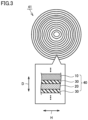
- a stack 40 illustrated in Fig. 2 includes a positive electrode plate 10, a negative electrode plate 20, and a separator 30. At least part of separator 30 is interposed between positive electrode plate 10 and negative electrode plate 20. Separator 30 separates positive electrode plate 10 from negative electrode plate 20. At least one of positive electrode plate 10 and negative electrode plate 20 is bonded to separator 30. Separator 30 may have an adhesive layer described below, on one side or both sides thereof.
- separator 30 has an adhesive layer described below, positive electrode plate 10 and/or negative electrode plate 20 may be bonded to separator 30 via the adhesive layer.
- each of the positive electrode plate, the negative electrode plate, and the separator may have a square planar shape, or may have a belt-like shape.
- the plan view of the positive electrode plate, the negative electrode plate, and the separator refers to the view in the thickness direction (the D-axis direction in Fig. 2 ).
- stack 40 may include two separators 30.
- stack 40 may include a single separator 30.
- positive electrode plate 10 may be sandwiched between two separators 30.
- negative electrode plate 20 may be sandwiched between two separators 30.
- stack 40 may be formed by stacking separator 30 (a first separator), negative electrode plate 20, separator 30 (a second separator), and positive electrode plate 10 in this order.
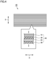
- stack 40 can be wound spirally.
- the stack can be wound around a cylinder-shaped core to form a tubular wound body 41 as illustrated in Fig. 3 .
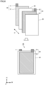
- a plurality of stacks 40 can be stacked on top of one another.
- the plurality of stacks 40 can be stacked to form a stack assembly 42 as illustrated in Fig. 4 .
- the stack is pressed at a temperature not higher than the glass transition temperature of the adhesion resin and at a pressure from 8 to 20 MPa, and thereby an electrode assembly for a non-aqueous electrolyte secondary battery is obtained.
- a temperature and a pressure within the above-mentioned range adhesion between the electrode plate and the separator is achieved to a proper degree during the production of the non-aqueous electrolyte secondary battery, and impregnation of non-aqueous electrolyte solution tends to be enhanced.
- the pressure in the pressing step (C) is the pressure applied to the pressed surface of the stack (surface pressure).
- the temperature at which the stack is pressed may be from 0 to 60°C, for example, and more preferably from 10 to 40°C, further preferably from 15°C to 35°C.
- the duration for which the stack is pressed may be not less than 1 second and less than 60 seconds, for example, or may be from 3 to 30 seconds, further preferably from 3 to 20 seconds.
- tubular wound body 41 described above can be pressed in a radial direction to form a flat electrode assembly 50 illustrated in Fig. 5 .
- stack assembly 42 described above can be pressed to form a stack-type electrode assembly 50 illustrated in Fig. 6 .
- the area ratio of the adhesive layer to the base material in the separator (hereinafter also called an adhesive layer area ratio) is from 10 to 70%.
- the adhesive layer area ratio falling within the above-mentioned range, adhesion between the electrode plate and the separator is achieved to a proper degree, and liquid-injection characteristics and liquid-impregnation characteristics of non-aqueous electrolyte solution tend to be enhanced.
- the adhesive layer area ratio is preferably from 10 to 60%.
- the adhesive layer area ratio is determined by a method that is described below in the Examples section.
- the adhesive layer area ratio can be adjusted to fall within the above-mentioned range, by adjusting the type and the number of the application/arrangement pattern for the adhesive layer formed on the base material, and/or the like, for example.
- the application/arrangement pattern can be, for example, the one in which an area with the adhesion resin and an area without the adhesion resin are alternately formed in the shape of grooves (a striped pattern), the one in which a plurality of circular areas with the adhesion resin are formed in a discontinuous manner (a dot pattern), and/or the like.
- the application/arrangement pattern may be an orderly pattern, or may be a random pattern.
- the positive electrode plate includes a positive electrode current collector and a positive electrode active material layer.
- the positive electrode plate can include the positive electrode active material layer on one side or both sides of the positive electrode current collector.
- a sheet or a foil made of a metal such as aluminum, nickel, titanium, and/or stainless steel can be used, for example, and preferably an aluminum foil is used.
- the thickness may be from 5 ⁇ m to 35 ⁇ m, for example, and preferably from 7 ⁇ m to 20 ⁇ m.
- the positive electrode active material layer includes a positive electrode active material.
- the positive electrode active material is not particularly limited, and one, two, or more types selected from those conventionally and typically used as a positive electrode active material for lithium-ion secondary batteries may be used.
- a lithium composite oxide, a lithium-(transition metal) phosphoric acid compound (LiFePO 4 , for example), and/or the like can be preferably used.
- lithium composite oxide examples include lithium-nickel-based composite oxide, lithium-cobalt-based composite oxide, lithium-manganese-based composite oxide, lithium-nickel-manganese-based composite oxide (LiNi 0.5 Mn 1.5 O 4 , for example), lithium-nickel-manganese-cobalt-based composite oxide (LiNi 1/3 Co 1/3 Mn 1/3 O 2 , for example), and the like.
- the positive electrode active material may be positive electrode active material particles.
- the average particle size of the positive electrode active material particles is not particularly limited, and may be approximately from 0.5 ⁇ m to 50 ⁇ m, typically from 1 ⁇ m to 20 ⁇ m.
- the positive electrode active material layer may contain a substance other than the positive electrode active material, such as, for example, a conductive material, a binder, and/or the like.
- a conductive material carbon black such as acetylene black (AB), and/or other carbon materials (such as graphite) can be preferably used, for example.
- AB acetylene black
- a fluorine-based binder such as polyvinylidene difluoride (PVdF) and/or polytetrafluoroethylene (PTFE) and/or a rubber-based binder such as styrene-butadiene rubber (SBR) can be preferably used, for example.
- the positive electrode active material layer may contain a material other than those described above (such as various additives, for example).
- the content of the positive electrode active material in the positive electrode active material layer (namely, the proportion of the positive electrode active material to the total mass of the positive electrode active material layer) is approximately 70 mass% or more. More preferably, it is from 75 mass% to 99 mass%, for example, and further preferably from 80 mass% to 97 mass%.
- the content of the conductive material in the positive electrode active material layer is preferably from 0.1 mass% to 20 mass%, for example, and more preferably from 1 mass% to 15 mass%.
- the content of the binder in the positive electrode active material layer is preferably from 0.5 mass% to 15 mass%, for example, and more preferably from 1 mass% to 10 mass%.
- the content of the additive(s) in the positive electrode active material layer is preferably 7 mass% or less, for example, and more preferably 5 mass% or less.
- the positive electrode plate can be produced by applying a positive electrode slurry that includes, for example, the positive electrode active material, the binder, and a certain amount of dispersion medium, to the positive electrode current collector, and drying, followed by compression.
- the positive electrode plate may be cut into a certain planar size suitable for the specifications of the electrode.
- the negative electrode plate includes a negative electrode current collector and a negative electrode active material layer.
- the negative electrode plate can include the negative electrode active material layer on one side or both sides of the negative electrode current collector.
- Examples of the negative electrode current collector include a sheet or a foil that is made of a metal with good electrical conductivity, such as copper, nickel, titanium, and/or stainless steel.
- a copper foil is preferably used as the negative electrode current collector. The dimension is not particularly limited, and may be decided as appropriate in accordance with the design of the battery. When a copper foil is used, the thickness may be from 5 ⁇ m to 35 ⁇ m, for example, and preferably from 7 ⁇ m to 20 ⁇ m.
- the negative electrode active material layer includes a negative electrode active material.
- a carbon material such as graphite, hard carbon, and/or soft carbon may be used, for example.
- the graphite may be either natural graphite or artificial graphite, and may be amorphous-carbon-coated graphite which is graphite coated with an amorphous carbon material.
- the negative electrode active material may be negative electrode active material particles.
- the average particle size of the negative electrode active material particles is not particularly limited, and it is, for example, from 0.1 ⁇ m to 50 ⁇ m, preferably from 1 ⁇ m to 25 ⁇ m, more preferably from 5 ⁇ m to 20 ⁇ m.
- the negative electrode active material layer may include a component other than the negative electrode active material, such as, for example, a binder, a thickener, and/or the like.
- a binder styrene-butadiene rubber (SBR), polyvinylidene difluoride (PVDF), and/or the like may be used, for example.
- PVDF polyvinylidene difluoride
- the thickener carboxymethylcellulose (CMC) and/or the like may be used, for example.
- the thickness of the negative electrode active material layer is not particularly limited, and may be, for example, from 10 ⁇ m to 300 ⁇ m, preferably from 20 ⁇ m to 200 ⁇ m.
- the content of the negative electrode active material in the negative electrode active material layer is preferably 90 mass% or more, more preferably from 95 mass% to 99 mass%.
- the content of the binder in the negative electrode active material layer is preferably from 0.1 mass% to 8 mass%, more preferably from 0.5 mass% to 3 mass%.
- the content of the thickener in the negative electrode active material layer is preferably from 0.3 mass% to 3 mass%, more preferably from 0.5 mass% to 2 mass%.
- the negative electrode plate can be produced by applying a negative electrode slurry that includes, for example, the negative electrode active material, the binder, and a certain amount of dispersion medium, to the negative electrode current collector, and drying, followed by compression.
- the negative electrode plate may be cut into a certain planar size suitable for the specifications of the electrode.
- the separator comprises a base material and an adhesive layer, and the adhesive layer is placed on at least one side of the base material and includes an adhesion resin.
- the separator is interposed between the positive electrode plate and the negative electrode plate, and is capable of separating the positive electrode plate from the negative electrode plate.
- the separator is electrically insulating.
- the base material can include a porous film.
- the base material may consist essentially of a porous film, for example.
- the porous film may be a resin film.
- the resin film may include polyolefin and/or the like, for example.
- the resin film may include at least one selected from the group consisting of polyethylene (PE) and polypropylene (PP), for example.
- the base material may have a monolayer structure, for example.
- the base material may consist essentially of a PE layer.
- the base material may have a multilayer structure, for example.
- the base material may be formed by stacking a PP layer, a PE layer, and a PP layer in this order, for example.
- the resin film may have a thickness from 3 to 50 ⁇ m, for example, or may have a thickness from 3 to 30 ⁇ m, or may have a thickness from 5 to 15 ⁇ m.
- the separator has an adhesive layer on one side or both sides of the base material.
- the adhesive layer is capable of bonding at least one of the positive electrode plate and the negative electrode plate with the separator (the base material) by the action of, for example, press molding.
- the adhesive layer includes an adhesion resin.
- the glass transition point of the adhesion resin may be higher than 35°C, for example, and may be 40°C or higher, or 50°C or higher.
- the glass transition point of the adhesion resin may be 70°C or lower, or 60°C or lower, for example, and may be 80°C or lower.
- adhesion resin examples include resin particles of a fluorine-based resin, an acrylic-based resin, a urethane resin, an ethylene vinyl acetate resin, an epoxy resin, and/or the like.
- fluorine-based resin examples include polyvinylidene difluoride (PVdF), polytetrafluoroethylene (PTFE), and the like.
- the separator can further comprise a heat-resistant layer.
- the heat-resistant layer can function to reduce shrinkage of the separator that can be caused by heat during charging and discharging of the battery.
- the heat-resistant layer can include inorganic particles and a binder, for example. Examples of the inorganic particles include ceramic particles of alumina, boehmite, aluminum hydroxide, silica, titania, and the like.
- the binder the resin materials described above as a constituent material of the adhesive layer can be used as appropriate.
- the mixing proportion of the inorganic particles and the binder is preferably from 98:2 to 50:50, more preferably from 95:5 to 70:30.
- the thickness of the heat-resistant layer may be from I to 10 ⁇ m, for example, and may be from 1 to 5 ⁇ m.
- the heat-resistant layer may be provided on one side or both sides of the base material.
- the heat-resistant layer is provided on a side of the separator that faces the positive electrode plate.
- the separator comprises a heat-resistant layer, it may be provided directly on the base material, or may be interposed between the base material and the adhesive layer.
- An electrode assembly according to the present disclosure comprises a positive electrode plate, a separator, and a negative electrode plate.
- the electrode assembly may be wound-type electrode assembly 50 illustrated in Fig. 5 .
- the electrode assembly may be stack-type electrode assembly 50 illustrated in Fig. 6 .
- the positive electrode plate, the separator, and the negative electrode plate the above description applies.
- the adhesion force between the base material and at least one of the positive electrode plate and the negative electrode plate placed in contact with the adhesive layer may be from 0.2 to 5.0 kN/m, for example. With the adhesion force falling within the above-mentioned range, electrode assembly formability as well as liquid-injection characteristics and liquid-impregnation characteristics of non-aqueous electrolyte solution tend to be achieved.
- the adhesion force is measured by an adhesion force measurement method that is described below in the Examples section. From the viewpoints of electrode assembly formability as well as liquid-injection characteristics and liquid-impregnation characteristics of non-aqueous electrolyte solution, the adhesion force may be preferably from 0.5 to 5.0 kN/m.
- the difference between the porosity of a portion that faces both a positive electrode active material application part and a negative electrode active material application part (also called an electrode plate facing portion) and the porosity of a portion that does not face at least one of the positive electrode active material application part and the negative electrode active material application part (also called an electrode plate not-facing portion) can be 8.0% or less, for example.
- the pore decrement is determined by a method that is described below in the Examples section.
- the pore decrement is preferably 4.0% or less, more preferably 3.0% or less, and, for example, it may be 1.5% or more.
- Fig. 7 is a schematic view illustrating an example configuration of a battery according to the present embodiment.
- a battery 100 may be used for any purpose of use. Battery 100 may be used as a main electric power supply or a motive force assisting electric power supply in an electric vehicle and/or the like. A plurality of batteries 100 may be connected together to form a battery module or a battery pack. Battery 100 may have a rated capacity from 1 to 300 Ah, for example.
- Battery 100 includes electrode assembly 50 and a non-aqueous electrolyte solution (not illustrated). As illustrated in Fig. 1 , battery 100 can further include an exterior package 90. Exterior package 90 accommodates electrode assembly 50 and the non-aqueous electrolyte solution. Exterior package 90 is prismatic (a flat, rectangular parallelepiped). Exterior package 90 may be made of aluminum (Al) alloy, for example. Electrode assembly 50 may be accommodated inside the exterior package 90, with pressure applied in the thickness direction (the D-axis direction in Fig. 7 ).
- Exterior package 90 may include a sealing plate 91 and an exterior container 92, for example. Sealing plate 91 closes the opening of exterior container 92. Sealing plate 91 and exterior container 92 may be bonded together by laser processing and/or the like, for example.
- the configuration of exterior package 90 is not particularly limited.
- exterior package 90 may be in the shape of a pouch. More specifically, exterior package 90 may be a pouch made of an Al-laminated film, and/or the like.
- a positive electrode terminal 81 and a negative electrode terminal 82 are provided.
- an inlet (not illustrated), a gas-discharge valve (not illustrated), and/or the like may further be provided. Through the inlet, the non-aqueous electrolyte solution may be injected into exterior package 90. The inlet may be closed with a plug and/or the like, for example.
- Positive electrode terminal 81 is connected with electrode assembly 50 by a positive electrode current-collecting member 71.
- Positive electrode current-collecting member 71 may be an Al plate and/or the like, for example.
- Negative electrode terminal 82 is connected with electrode assembly 50 by a negative electrode current-collecting member 72.
- Negative electrode current-collecting member 72 may be a copper (Cu) plate and/or the like, for example.
- non-aqueous electrolyte solution a liquid that is made by dissolving or dispersing an electrolyte salt (in other words, a supporting salt) in a non-aqueous solvent is used.
- the non-aqueous solvent is not particularly limited, and various organic solvents such as carbonates, ethers, esters, nitriles, sulfones, and lactones that are used for an electrolyte solution of a typical lithium-ion secondary battery can be used.
- Carbonates are preferable among them, and specific examples thereof include ethylene carbonate (EC), propylene carbonate (PC), diethyl carbonate (DEC), dimethyl carbonate (DMC), ethyl methyl carbonate (EMC), monofluoroethylene carbonate (MFEC), difluoroethylene carbonate (DFEC), monofluoromethyldifluoromethyl carbonate (F-DMC), trifluorodimethyl carbonate (TFDMC), and the like.
- EC ethylene carbonate
- PC propylene carbonate
- DEC diethyl carbonate
- DMC dimethyl carbonate
- EMC ethyl methyl carbonate
- EMC ethyl methyl carbonate
- MFEC monofluoroethylene carbonate
- DFEC difluoroethylene carbonate
- F-DMC monofluoromethyldifluoromethyl carbonate
- TFDMC trifluorodimethyl carbonate
- a lithium salt such as LiPF 6 , LiBF 4 , and/or lithium bis(fluorosulfonyl)imide (LiFSI) can be used, for example, and, among them, LiPF 6 is preferable.
- the concentration of the electrolyte salt is not particularly limited, and it is preferably from 0.7 mol/L to 1.3 mol/L.
- the non-aqueous electrolyte solution may include a component other than the above-described components, such as, for example, various additives including a film-forming agent such as an oxalato complex, biphenyl (BP), a gas generation agent such as cyclohexylbenzene (CHB), a thickener, and the like.
- a film-forming agent such as an oxalato complex, biphenyl (BP), a gas generation agent such as cyclohexylbenzene (CHB), a thickener, and the like.
- a separator was prepared, which included a heat-resistant layer on one side of a PE film and which also included an adhesive layer on each side of the film (that included an adhesion resin with a glass transition temperature of 35°C or more).
- the electrode assembly produced in Examples and Comparative Examples was cut into a size of 2 cm ⁇ 7 cm.
- the adhesion force between the substrate and the positive electrode plate was measured by a method in conformity with JIS K6854-1, under the conditions of a strain rate of 50 mm/minute. When the adhesion force is 0.2 kN/m or more, it is judged that adhesion between the separator and the electrode plate is sufficiently ensured and the electrode assembly formability is good.
- the electrode assembly produced in Examples and Comparative Examples was disassembled, and the separator was separated. Subsequently, the separator was set on a platform of a microscope in such a manner that the surface whose adhesive covering rate was to be calculated faced upward, and examination was carried out under a magnification from 10 to 200. At this point, if the application/arrangement pattern of the adhesive was available, the magnification was adjusted so that at least one cycle was to be examined. Binarization processing was performed so that only the adhesive-covered position was distinguished within the examination area, and the adhesive layer area ratio was calculated.
- An end of the electrode assembly produced in Examples and Comparative Examples was immersed in a non-aqueous electrolyte solution in a tray, and taken out after a lapse of 6 hours. Subsequently, the electrode assembly thus being subjected to impregnation evaluation was disassembled, and the height to which the non-aqueous electrolyte solution permeated and reached from the immersed end was measured, followed by evaluation of impregnation of the non-aqueous electrolyte solution according to the criteria described below.
- the electrode assembly produced in Examples and Comparative Examples was disassembled, and the separator was taken out.
- the true density ⁇ t of the base material of the separator at the electrode plate facing portion and the electrode plate not-facing portion, respectively, was determined by a gas replacement method. As the gas, He was used.
- the porosity of the base material at the electrode plate facing portion and the electrode plate not-facing portion, respectively was calculated by (1- ⁇ / ⁇ t) ⁇ 100.
- the pore decrement was calculated by (1-(porosity of electrode plate facing portion)/(porosity of electrode plate not-facing portion)) ⁇ 100. When the pore decrement is 8.0% or less, it is judged that the pores remain to be present without collapsing due to pressing and the non-aqueous electrolyte solution has good liquid-injection characteristics and good liquid-impregnation characteristics.
- the positive electrode plate and the negative electrode plate were stacked with the separator interposed therebetween, and thereby a stack was produced.
- the resulting stack was pressed at a pressing temperature of 25°C and a pressing pressure of 10 MPa for a pressing duration of 3 seconds, and thereby an electrode assembly was produced.
- the resulting electrode assembly was subjected to evaluation of the adhesion force between the electrode plate and the separator, the adhesive layer area ratio, the rate of impregnation, and the pore decrement. Results are shown in Table 1.
- the electrode assembly obtained in each of Examples 1 to 8 according to the present disclosure had a sufficient adhesion force, a sufficient rate of impregnation of non-aqueous electrolyte solution, and a low pore decrement.
- the present disclosure makes it possible to provide an electrode assembly for a non-aqueous electrolyte secondary battery that can exhibit electrode assembly formability as well as liquid-injection characteristics and liquid-impregnation characteristics of electrolyte solution, and also to provide a method of producing the same.
Landscapes
- Chemical & Material Sciences (AREA)
- Chemical Kinetics & Catalysis (AREA)
- Electrochemistry (AREA)
- General Chemical & Material Sciences (AREA)
- Engineering & Computer Science (AREA)
- Manufacturing & Machinery (AREA)
- Materials Engineering (AREA)
- Secondary Cells (AREA)
- Battery Electrode And Active Subsutance (AREA)
- Cell Separators (AREA)
Applications Claiming Priority (1)
| Application Number | Priority Date | Filing Date | Title |
|---|---|---|---|
| JP2023109073A JP2025007578A (ja) | 2023-07-03 | 2023-07-03 | 非水電解質二次電池用電極体の製造方法、電極体及び電池 |
Publications (2)
| Publication Number | Publication Date |
|---|---|
| EP4489158A2 true EP4489158A2 (de) | 2025-01-08 |
| EP4489158A3 EP4489158A3 (de) | 2025-05-28 |
Family
ID=91247147
Family Applications (1)
| Application Number | Title | Priority Date | Filing Date |
|---|---|---|---|
| EP24177882.8A Pending EP4489158A3 (de) | 2023-07-03 | 2024-05-24 | Verfahren zur herstellung einer elektrodenanordnung für eine sekundärbatterie mit wasserfreiem elektrolyt, elektrodenanordnung und batterie |
Country Status (4)
| Country | Link |
|---|---|
| US (1) | US20250015442A1 (de) |
| EP (1) | EP4489158A3 (de) |
| JP (1) | JP2025007578A (de) |
| CN (1) | CN119253083A (de) |
Citations (1)
| Publication number | Priority date | Publication date | Assignee | Title |
|---|---|---|---|---|
| JP2011054502A (ja) | 2009-09-04 | 2011-03-17 | Hitachi Maxell Ltd | リチウム二次電池およびその製造方法 |
Family Cites Families (8)
| Publication number | Priority date | Publication date | Assignee | Title |
|---|---|---|---|---|
| JP5499758B2 (ja) * | 2010-02-22 | 2014-05-21 | 三洋電機株式会社 | 非水電解質二次電池及びその製造方法 |
| WO2016204274A1 (ja) * | 2015-06-19 | 2016-12-22 | 宇部興産株式会社 | ポリオレフィン微多孔膜、蓄電デバイス用セパレータフィルム、および蓄電デバイス |
| WO2017159025A1 (ja) * | 2016-03-15 | 2017-09-21 | ソニー株式会社 | 光電変換素子および固体撮像装置 |
| KR102155635B1 (ko) * | 2016-04-01 | 2020-09-14 | 주식회사 엘지화학 | 접착층을 포함하는 전기화학소자용 분리막 및 상기 분리막을 포함하는 전극 조립체 |
| PL3780171T3 (pl) * | 2018-03-26 | 2023-11-27 | Zeon Corporation | Sposób wytwarzania warstwowego korpusu niewodnej baterii akumulatorowej i sposób wytwarzania niewodnej baterii akumulatorowej |
| CN117223145A (zh) * | 2021-04-28 | 2023-12-12 | 日本瑞翁株式会社 | 非水系二次电池黏合层用组合物、非水系二次电池用黏合层及其制造方法、非水系二次电池用层叠体及其制造方法、以及非水系二次电池 |
| JP7638204B2 (ja) * | 2021-12-22 | 2025-03-03 | プライムプラネットエナジー&ソリューションズ株式会社 | セパレータ及びこれを備える非水電解液二次電池並びに組電池 |
| WO2024143477A1 (ja) * | 2022-12-28 | 2024-07-04 | 旭化成株式会社 | 蓄電デバイス用セパレータ |
-
2023
- 2023-07-03 JP JP2023109073A patent/JP2025007578A/ja active Pending
-
2024
- 2024-05-24 EP EP24177882.8A patent/EP4489158A3/de active Pending
- 2024-06-05 US US18/733,851 patent/US20250015442A1/en active Pending
- 2024-07-01 CN CN202410868547.7A patent/CN119253083A/zh active Pending
Patent Citations (1)
| Publication number | Priority date | Publication date | Assignee | Title |
|---|---|---|---|---|
| JP2011054502A (ja) | 2009-09-04 | 2011-03-17 | Hitachi Maxell Ltd | リチウム二次電池およびその製造方法 |
Also Published As
| Publication number | Publication date |
|---|---|
| CN119253083A (zh) | 2025-01-03 |
| JP2025007578A (ja) | 2025-01-17 |
| EP4489158A3 (de) | 2025-05-28 |
| US20250015442A1 (en) | 2025-01-09 |
Similar Documents
| Publication | Publication Date | Title |
|---|---|---|
| JP5167703B2 (ja) | 電池用電極 | |
| EP3683860B1 (de) | Trenner für eine sekundärbatterie mit wasserfreiem elektrolyt und sekundärbatterie mit wasserfreiem elektrolyt | |
| KR101843577B1 (ko) | 비수 전해질 2차 전지 및 그 제조 방법 | |
| KR101639923B1 (ko) | 내열 절연층을 갖는 세퍼레이터 | |
| US7960050B2 (en) | Secondary cell and its manufacturing method | |
| KR101115725B1 (ko) | 리튬 이온 2차 전지 | |
| EP4084125B1 (de) | Negativelektrode für sekundärbatterien mit wasserfreiem elektrolyt und sekundärbatterie mit wasserfreiem elektrolyt | |
| EP3627586B1 (de) | Separator für nichtwässrige sekundärbatterien, nichtwässrige sekundärbatterie und verfahren zur herstellung einer nichtwässrigen sekundärbatterie | |
| EP3471170B1 (de) | Sekundärbatterie mit wasserfreiem elektrolyt | |
| JP5601361B2 (ja) | 電池用電極 | |
| KR101944443B1 (ko) | 비수 전해질 이차 전지, 상기 비수 전해질 이차 전지에 사용되는 전극체, 및 상기 전극체의 제조방법 | |
| EP3851841B1 (de) | Vorrichtung und verfahren zur widerstandsmessung eines unter druck stehenden abscheiders | |
| KR101846767B1 (ko) | 비수 전해질 2차 전지 | |
| US20250066568A1 (en) | Polyolefin-based film and preparation method thereof, separator, secondary battery, and electric apparatus | |
| EP4597724A1 (de) | Separator und herstellungsverfahren dafür, sekundärbatterie und elektrische vorrichtung | |
| US20150263334A1 (en) | Non-aqueous electrolyte secondary battery | |
| EP3086390B1 (de) | Sekundärbatterie mit nichtwässrigem elektrolyt | |
| JP7236039B2 (ja) | 非水電解液蓄電デバイスおよび非水電解液蓄電デバイスの製造方法 | |
| US20250372616A1 (en) | Positive electrode sheet, secondary battery, and electric device | |
| CN114597333B (zh) | 非水电解质二次电池 | |
| KR102391534B1 (ko) | 음극, 및 상기 음극을 포함하는 리튬 이차 전지 | |
| EP4718543A2 (de) | Batteriestromkollektor und herstellungsverfahren dafür, sekundärbatterie, batteriemodul, batteriepack und elektrische vorrichtung | |
| EP4489158A2 (de) | Verfahren zur herstellung einer elektrodenanordnung für eine sekundärbatterie mit wasserfreiem elektrolyt, elektrodenanordnung und batterie | |
| EP4030498B1 (de) | Graphitbasiertes negativelektrodenaktivmaterial | |
| EP4611155A1 (de) | Separator, sekundärbatterie und elektrische vorrichtung |
Legal Events
| Date | Code | Title | Description |
|---|---|---|---|
| PUAI | Public reference made under article 153(3) epc to a published international application that has entered the european phase |
Free format text: ORIGINAL CODE: 0009012 |
|
| STAA | Information on the status of an ep patent application or granted ep patent |
Free format text: STATUS: REQUEST FOR EXAMINATION WAS MADE |
|
| 17P | Request for examination filed |
Effective date: 20240524 |
|
| AK | Designated contracting states |
Kind code of ref document: A2 Designated state(s): AL AT BE BG CH CY CZ DE DK EE ES FI FR GB GR HR HU IE IS IT LI LT LU LV MC ME MK MT NL NO PL PT RO RS SE SI SK SM TR |
|
| PUAL | Search report despatched |
Free format text: ORIGINAL CODE: 0009013 |
|
| AK | Designated contracting states |
Kind code of ref document: A3 Designated state(s): AL AT BE BG CH CY CZ DE DK EE ES FI FR GB GR HR HU IE IS IT LI LT LU LV MC ME MK MT NL NO PL PT RO RS SE SI SK SM TR |
|
| RIC1 | Information provided on ipc code assigned before grant |
Ipc: H01M 50/46 20210101ALI20250422BHEP Ipc: H01M 10/05 20100101ALI20250422BHEP Ipc: H01M 10/0587 20100101ALI20250422BHEP Ipc: H01M 10/04 20060101AFI20250422BHEP |