EP4488589A2 - Heat source unit and scroll compressor - Google Patents
Heat source unit and scroll compressor Download PDFInfo
- Publication number
- EP4488589A2 EP4488589A2 EP24214784.1A EP24214784A EP4488589A2 EP 4488589 A2 EP4488589 A2 EP 4488589A2 EP 24214784 A EP24214784 A EP 24214784A EP 4488589 A2 EP4488589 A2 EP 4488589A2
- Authority
- EP
- European Patent Office
- Prior art keywords
- pipe
- scroll
- source unit
- heat source
- fixing member
- Prior art date
- Legal status (The legal status is an assumption and is not a legal conclusion. Google has not performed a legal analysis and makes no representation as to the accuracy of the status listed.)
- Granted
Links
Images


Classifications
-
- F—MECHANICAL ENGINEERING; LIGHTING; HEATING; WEAPONS; BLASTING
- F25—REFRIGERATION OR COOLING; COMBINED HEATING AND REFRIGERATION SYSTEMS; HEAT PUMP SYSTEMS; MANUFACTURE OR STORAGE OF ICE; LIQUEFACTION SOLIDIFICATION OF GASES
- F25B—REFRIGERATION MACHINES, PLANTS OR SYSTEMS; COMBINED HEATING AND REFRIGERATION SYSTEMS; HEAT PUMP SYSTEMS
- F25B31/00—Compressor arrangements
-
- F—MECHANICAL ENGINEERING; LIGHTING; HEATING; WEAPONS; BLASTING
- F25—REFRIGERATION OR COOLING; COMBINED HEATING AND REFRIGERATION SYSTEMS; HEAT PUMP SYSTEMS; MANUFACTURE OR STORAGE OF ICE; LIQUEFACTION SOLIDIFICATION OF GASES
- F25B—REFRIGERATION MACHINES, PLANTS OR SYSTEMS; COMBINED HEATING AND REFRIGERATION SYSTEMS; HEAT PUMP SYSTEMS
- F25B31/00—Compressor arrangements
- F25B31/02—Compressor arrangements of motor-compressor units
- F25B31/026—Compressor arrangements of motor-compressor units with compressor of rotary type
-
- F—MECHANICAL ENGINEERING; LIGHTING; HEATING; WEAPONS; BLASTING
- F04—POSITIVE - DISPLACEMENT MACHINES FOR LIQUIDS; PUMPS FOR LIQUIDS OR ELASTIC FLUIDS
- F04B—POSITIVE-DISPLACEMENT MACHINES FOR LIQUIDS; PUMPS
- F04B39/00—Component parts, details, or accessories, of pumps or pumping systems specially adapted for elastic fluids, not otherwise provided for in, or of interest apart from, groups F04B25/00 - F04B37/00
-
- F—MECHANICAL ENGINEERING; LIGHTING; HEATING; WEAPONS; BLASTING
- F04—POSITIVE - DISPLACEMENT MACHINES FOR LIQUIDS; PUMPS FOR LIQUIDS OR ELASTIC FLUIDS
- F04C—ROTARY-PISTON, OR OSCILLATING-PISTON, POSITIVE-DISPLACEMENT MACHINES FOR LIQUIDS; ROTARY-PISTON, OR OSCILLATING-PISTON, POSITIVE-DISPLACEMENT PUMPS
- F04C18/00—Rotary-piston pumps specially adapted for elastic fluids
- F04C18/02—Rotary-piston pumps specially adapted for elastic fluids of arcuate-engagement type, i.e. with circular translatory movement of co-operating members, each member having the same number of teeth or tooth-equivalents
- F04C18/0207—Rotary-piston pumps specially adapted for elastic fluids of arcuate-engagement type, i.e. with circular translatory movement of co-operating members, each member having the same number of teeth or tooth-equivalents both members having co-operating elements in spiral form
- F04C18/0215—Rotary-piston pumps specially adapted for elastic fluids of arcuate-engagement type, i.e. with circular translatory movement of co-operating members, each member having the same number of teeth or tooth-equivalents both members having co-operating elements in spiral form where only one member is moving
-
- F—MECHANICAL ENGINEERING; LIGHTING; HEATING; WEAPONS; BLASTING
- F04—POSITIVE - DISPLACEMENT MACHINES FOR LIQUIDS; PUMPS FOR LIQUIDS OR ELASTIC FLUIDS
- F04C—ROTARY-PISTON, OR OSCILLATING-PISTON, POSITIVE-DISPLACEMENT MACHINES FOR LIQUIDS; ROTARY-PISTON, OR OSCILLATING-PISTON, POSITIVE-DISPLACEMENT PUMPS
- F04C2/00—Rotary-piston machines or pumps
- F04C2/02—Rotary-piston machines or pumps of arcuate-engagement type, i.e. with circular translatory movement of co-operating members, each member having the same number of teeth or tooth-equivalents
- F04C2/025—Rotary-piston machines or pumps of arcuate-engagement type, i.e. with circular translatory movement of co-operating members, each member having the same number of teeth or tooth-equivalents the moving and the stationary member having co-operating elements in spiral form
-
- F—MECHANICAL ENGINEERING; LIGHTING; HEATING; WEAPONS; BLASTING
- F04—POSITIVE - DISPLACEMENT MACHINES FOR LIQUIDS; PUMPS FOR LIQUIDS OR ELASTIC FLUIDS
- F04C—ROTARY-PISTON, OR OSCILLATING-PISTON, POSITIVE-DISPLACEMENT MACHINES FOR LIQUIDS; ROTARY-PISTON, OR OSCILLATING-PISTON, POSITIVE-DISPLACEMENT PUMPS
- F04C29/00—Component parts, details or accessories of pumps or pumping installations, not provided for in groups F04C18/00 - F04C28/00
- F04C29/06—Silencing
- F04C29/065—Noise dampening volumes, e.g. muffler chambers
-
- F—MECHANICAL ENGINEERING; LIGHTING; HEATING; WEAPONS; BLASTING
- F04—POSITIVE - DISPLACEMENT MACHINES FOR LIQUIDS; PUMPS FOR LIQUIDS OR ELASTIC FLUIDS
- F04C—ROTARY-PISTON, OR OSCILLATING-PISTON, POSITIVE-DISPLACEMENT MACHINES FOR LIQUIDS; ROTARY-PISTON, OR OSCILLATING-PISTON, POSITIVE-DISPLACEMENT PUMPS
- F04C29/00—Component parts, details or accessories of pumps or pumping installations, not provided for in groups F04C18/00 - F04C28/00
- F04C29/06—Silencing
- F04C29/068—Silencing the silencing means being arranged inside the pump housing
-
- F—MECHANICAL ENGINEERING; LIGHTING; HEATING; WEAPONS; BLASTING
- F24—HEATING; RANGES; VENTILATING
- F24F—AIR-CONDITIONING; AIR-HUMIDIFICATION; VENTILATION; USE OF AIR CURRENTS FOR SCREENING
- F24F1/00—Room units for air-conditioning, e.g. separate or self-contained units or units receiving primary air from a central station
- F24F1/06—Separate outdoor units, e.g. outdoor unit to be linked to a separate room comprising a compressor and a heat exchanger
- F24F1/08—Compressors specially adapted for separate outdoor units
- F24F1/12—Vibration or noise prevention thereof
-
- F—MECHANICAL ENGINEERING; LIGHTING; HEATING; WEAPONS; BLASTING
- F25—REFRIGERATION OR COOLING; COMBINED HEATING AND REFRIGERATION SYSTEMS; HEAT PUMP SYSTEMS; MANUFACTURE OR STORAGE OF ICE; LIQUEFACTION SOLIDIFICATION OF GASES
- F25B—REFRIGERATION MACHINES, PLANTS OR SYSTEMS; COMBINED HEATING AND REFRIGERATION SYSTEMS; HEAT PUMP SYSTEMS
- F25B41/00—Fluid-circulation arrangements
- F25B41/40—Fluid line arrangements
-
- F—MECHANICAL ENGINEERING; LIGHTING; HEATING; WEAPONS; BLASTING
- F04—POSITIVE - DISPLACEMENT MACHINES FOR LIQUIDS; PUMPS FOR LIQUIDS OR ELASTIC FLUIDS
- F04C—ROTARY-PISTON, OR OSCILLATING-PISTON, POSITIVE-DISPLACEMENT MACHINES FOR LIQUIDS; ROTARY-PISTON, OR OSCILLATING-PISTON, POSITIVE-DISPLACEMENT PUMPS
- F04C2240/00—Components
- F04C2240/30—Casings or housings
-
- F—MECHANICAL ENGINEERING; LIGHTING; HEATING; WEAPONS; BLASTING
- F04—POSITIVE - DISPLACEMENT MACHINES FOR LIQUIDS; PUMPS FOR LIQUIDS OR ELASTIC FLUIDS
- F04C—ROTARY-PISTON, OR OSCILLATING-PISTON, POSITIVE-DISPLACEMENT MACHINES FOR LIQUIDS; ROTARY-PISTON, OR OSCILLATING-PISTON, POSITIVE-DISPLACEMENT PUMPS
- F04C2240/00—Components
- F04C2240/80—Other components
- F04C2240/806—Pipes for fluids; Fittings therefor
-
- F—MECHANICAL ENGINEERING; LIGHTING; HEATING; WEAPONS; BLASTING
- F04—POSITIVE - DISPLACEMENT MACHINES FOR LIQUIDS; PUMPS FOR LIQUIDS OR ELASTIC FLUIDS
- F04C—ROTARY-PISTON, OR OSCILLATING-PISTON, POSITIVE-DISPLACEMENT MACHINES FOR LIQUIDS; ROTARY-PISTON, OR OSCILLATING-PISTON, POSITIVE-DISPLACEMENT PUMPS
- F04C2270/00—Control; Monitoring or safety arrangements
- F04C2270/12—Vibration
-
- F—MECHANICAL ENGINEERING; LIGHTING; HEATING; WEAPONS; BLASTING
- F25—REFRIGERATION OR COOLING; COMBINED HEATING AND REFRIGERATION SYSTEMS; HEAT PUMP SYSTEMS; MANUFACTURE OR STORAGE OF ICE; LIQUEFACTION SOLIDIFICATION OF GASES
- F25B—REFRIGERATION MACHINES, PLANTS OR SYSTEMS; COMBINED HEATING AND REFRIGERATION SYSTEMS; HEAT PUMP SYSTEMS
- F25B2400/00—Component parts or details not otherwise provided for in this subclass
- F25B2400/13—Economisers
-
- F—MECHANICAL ENGINEERING; LIGHTING; HEATING; WEAPONS; BLASTING
- F25—REFRIGERATION OR COOLING; COMBINED HEATING AND REFRIGERATION SYSTEMS; HEAT PUMP SYSTEMS; MANUFACTURE OR STORAGE OF ICE; LIQUEFACTION SOLIDIFICATION OF GASES
- F25B—REFRIGERATION MACHINES, PLANTS OR SYSTEMS; COMBINED HEATING AND REFRIGERATION SYSTEMS; HEAT PUMP SYSTEMS
- F25B2500/00—Problems to be solved
- F25B2500/13—Vibrations
Definitions
- It relates to a heat source unit and a scroll compressor.
- a heat source unit such as an air conditioner includes a compressor.
- the compressor sucks a low-pressure gas refrigerant into a compression chamber of the compressor, compresses the low-pressure gas refrigerant into a high-pressure gas refrigerant, and discharges the high-pressure gas refrigerant. Therefore, a suction pipe and a discharge pipe are connected to the compression chamber of the compressor.
- Some compressors implement a technique called gas injection in order to improve performance of a refrigerant circuit. In the gas injection, a pipe called an injection pipe is connected to the compression chamber of the compressor.
- Patent Literature 1 JP 2011-94914 A discloses a configuration of suppressing vibration during operation, but does not disclose a configuration of dealing with excitation applied during transportation.
- Aim of the present invention is to provide a heat source unit and a compressor which improve the state of the art indicated above. This aim is achieved by the heat source unit and the compressor according to one or more of the corresponding appended claims.
- a heat source unit of a refrigerant cycle apparatus includes a compressor, pipes, and a fixing member.
- the compressor has two or three connection portions among a first connection portion, a second connection portion, and a third connection portion.
- the first connection portion connects a suction pipe.
- the second connection portion connects a discharge pipe.
- the third connection portion connects an injection pipe.
- Each of the pipes has a vertical portion.
- the vertical portion is a portion at least a part of which extends vertically from each of the two or three connection portions.
- the fixing member fixes at least two pipes of two or three of the pipes to each other at the vertical portions. In top view, each of the connection portions of the pipes fixed by the fixing member is located on one first straight line.
- the heat source unit of the refrigerant cycle apparatus suppresses malfunction caused by vibration of the heat source unit during operation and excitation during transportation.
- a heat source unit of a refrigerant cycle apparatus is the heat source unit according to the first aspect, in which the compressor further includes a casing and three or four legs provided below the casing. At least one of the legs exists on a second straight line in top view. The second straight line passes through a center of the casing and is orthogonal to the first straight line.
- This configuration contributes to suppression of malfunction of the heat source unit of the refrigerant cycle apparatus.
- a heat source unit of a refrigerant cycle apparatus is the heat source unit of the refrigerant cycle apparatus according to the second aspect, in which each of the three or four legs is attached with a vibration-proof rubber.
- a heat source unit of a refrigerant cycle apparatus is the heat source unit of the refrigerant cycle apparatus according to the second aspect, in which at least the leg located at a position farthest from the first straight line among the three or four legs is attached with the vibration-proof rubber different in type from the vibration-proof rubber attached to the legs other than the leg located at the position farthest from the first straight line.
- a heat source unit of a refrigerant cycle apparatus is the heat source unit according to any one of the first to fourth aspects, in which the first connection portion, the second connection portion, and the third connection portion are located on the first straight line in top view.
- the fixing member fixes the suction pipe, the discharge pipe, or the injection pipe to each other.
- a heat source unit of a refrigerant cycle apparatus is the heat source unit according to any one of the first to fifth aspects, in which the injection pipe includes a silencer.
- a heat source unit of a refrigerant cycle apparatus is the heat source unit according to any one of the first to sixth aspects, in which the fixing member is made from metal.
- a compressor includes a casing, two or three connection portions, and three or four legs.
- Two or three pipes among a suction pipe, a discharge pipe, and an injection pipe are fixed to the casing.
- the two or three connection portions are two or three connection portions among a first connection portion, a second connection portion, and a third connection portion.
- the first connection portion connects a suction pipe.
- the second connection portion connects a discharge pipe.
- the third connection portion connects an injection pipe.
- the three or four legs are provided below the casing.
- the connection portions are located on one first straight line. At least one of the legs exists on a second straight line.
- the second straight line passes through a center of the casing and is orthogonal to the first straight line.
- a scroll compressor includes two or three connection portions among a first connection portion, a second connection portion, and a third connection portion, and a scroll compression mechanism.
- the first connection portion connects a suction pipe.
- the second connection portion connects a discharge pipe.
- the third connection portion connects an injection pipe.
- the scroll compression mechanism includes a fixed scroll, a movable scroll, and an Oldham coupling.
- an angle formed between a first direction in which a pipe fixing member extends in top view and a reciprocating direction of the Oldham coupling is 10° or less.
- the pipe fixing member fixes two or three pipes among the suction pipe, the discharge pipe, and the injection pipe.
- Patent Literature 2 JP H02-485 A discloses that vibration is transmitted in a predetermined direction by using a balance weight in consideration of the inertial force. However, by adding the balance weight, manufacturing costs of the scroll compressor and the heat source unit increase.
- designing the pipes side by side makes it possible to suppress the vibration of the Oldham coupling in the reciprocating direction without increasing the manufacturing costs.
- a heat source unit of a refrigerant cycle apparatus includes the scroll compressor according to the ninth aspect, a suction pipe, a discharge pipe, an injection pipe, and a pipe fixing member.
- the suction pipe has a first vertical portion connected to a first connection portion.
- the discharge pipe has a second vertical portion connected to a second connection portion.
- the injection pipe has a third vertical portion connected to a third connection portion.
- the pipe fixing member fixes two or three pipes among the suction pipe, the discharge pipe, and the injection pipe.
- a heat source unit of a refrigerant cycle apparatus is the heat source unit according to the tenth aspect, in which the pipe fixing member fixes the discharge pipe and the injection pipe.
- This configuration contributes to suppression of vibration of the heat source unit.
- a heat source unit of a refrigerant cycle apparatus is the heat source unit according to the tenth aspect, in which the pipe fixing member fixes the suction pipe and the injection pipe.
- This configuration contributes to suppression of vibration of the heat source unit.
- a heat source unit of a refrigerant cycle apparatus is the heat source unit according to the tenth aspect, in which the pipe fixing member fixes the discharge pipe and the suction pipe.
- This configuration contributes to suppression of vibration of the heat source unit.
- a heat source unit of a refrigerant cycle apparatus is the heat source unit according to the tenth aspect, in which the pipe fixing member fixes the suction pipe, the discharge pipe, and the injection pipe.
- This configuration contributes to suppression of vibration of the heat source unit.
- a heat source unit of a refrigerant cycle apparatus is the heat source unit according to any one of the tenth to fourteenth aspects, in which the pipe fixing member is made from metal.
- This configuration contributes to ensuring reliability of the heat source unit.
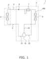
- FIG. 1 is a refrigerant circuit diagram of a refrigerant cycle apparatus 1 using a scroll compressor 10 according to one embodiment of the present invention.
- the refrigerant cycle apparatus 1 employing the scroll compressor 10 include a "refrigerant cycle apparatus dedicated to cooling operation”, a “refrigerant cycle apparatus dedicated to heating operation”, and a “refrigerant cycle apparatus switchable to cooling operation or heating operation by using a four-way switching valve".
- description will be made with a "refrigerant cycle apparatus dedicated to cooling operation”.
- the refrigerant cycle apparatus 1 includes a utilization unit 2 and a heat source unit 3, and the utilization unit 2 and the heat source unit 3 are connected to each other by a liquid refrigerant connection pipe 4 and a gas refrigerant connection pipe 5.
- the refrigerant cycle apparatus 1 is of a separate type including one utilization unit 2 and one heat source unit 3.
- the present invention is not limited thereto.
- the refrigerant cycle apparatus 1 may be of a multi-type including a plurality of utilization units 2.
- devices such as the scroll compressor 10, an outdoor heat exchanger 6, an economizer heat exchanger 7, an expansion valve 8, and an indoor heat exchanger 9 are connected by pipes to constitute a refrigerant circuit 100.
- the indoor heat exchanger 9 mounted on the utilization unit 2 is a cross-fin type fin-and-tube heat exchanger including a heat transfer tube and a large number of heat transfer fins.
- the indoor heat exchanger 9 has a liquid side connected to the liquid refrigerant connection pipe 4 and a gas side connected to the gas refrigerant connection pipe 5, and functions as an evaporator for refrigerant.
- the heat source unit 3 is equipped with the scroll compressor 10, the outdoor heat exchanger 6, the economizer heat exchanger 7, the expansion valve 8, and the like.
- the scroll compressor 10 will be described in detail later.
- the outdoor heat exchanger 6 is a cross-fin type fin-and-tube heat exchanger including a heat transfer tube and a large number of heat transfer fins.
- One side of the outdoor heat exchanger 6 is connected to a discharge pipe 22 through which the refrigerant discharged from the scroll compressor 10 flows, and the other side of the outdoor heat exchanger 6 is connected to a suction pipe 21.
- the outdoor heat exchanger 6 functions as a condenser for a gas refrigerant supplied from the scroll compressor 10 via the discharge pipe 22.
- the economizer heat exchanger 7 is disposed between the outdoor heat exchanger 6 and the expansion valve 8.
- the economizer heat exchanger 7 causes heat exchange between the refrigerant flowing from the outdoor heat exchanger 6 toward the expansion valve 8 and the refrigerant flowing through an injection pipe 23.
- the expansion valve 8 is provided on a pipe connecting the outdoor heat exchanger 6 and the liquid refrigerant connection pipe 4.
- the expansion valve 8 is an electric valve whose opening degree is adjustable for adjusting a pressure and a flow rate of the refrigerant flowing through the pipe.
- FIG. 2 is a longitudinal sectional view of the scroll compressor 10 according to one embodiment of the present invention.
- FIG. 3 is a schematic view showing appearance of the scroll compressor 10.
- FIG. 4 is a schematic top view of the scroll compressor 10.
- the scroll compressor 10 according to one embodiment of the present invention is a so-called all-hermetic compressor, is connected to the refrigerant circuit 100 that performs a refrigeration cycle, and sucks and compresses a refrigerant in the refrigerant circuit 100.
- the scroll compressor 10 is fixed to a bottom plate 12 of the heat source unit 3.
- a scroll compression mechanism 50 as a body mechanism, an electric motor 30, a lower bearing member 44, and a drive shaft 40 as a rotary shaft are accommodated in an internal space of a casing 11.
- the casing 11 is a sealed container having a vertically long cylindrical shape.
- the scroll compression mechanism 50, the electric motor 30, and the lower bearing member 44 are disposed in order from top to bottom.
- the drive shaft 40 is disposed such that its axial direction is along a height direction of the casing 11. A detailed structure of the scroll compression mechanism 50 will be described later.
- the suction pipe 21, the discharge pipe 22, and the injection pipe 23 are attached to the casing 11 as pipes.
- the suction pipe 21 is connected via a first connection portion 21A to a first vertical portion 21B which is a vertically extending portion of the suction pipe 21.
- a part of the first vertical portion 21B is welded and fixed to an upper lid 11a of the casing 11.
- a lower end of the first vertical portion 21B is connected to a fixed scroll 60 of the scroll compression mechanism 50.
- the suction pipe 21 communicates with a compression chamber Sc of the scroll compression mechanism 50 via the first vertical portion 21B.
- a low-pressure refrigerant in the refrigeration cycle before being compressed by the scroll compressor 10 flows through the suction pipe 21 and the first vertical portion 21B.
- the discharge pipe 22 is connected via a second connection portion 22A to a second vertical portion 22B which is a vertically extending portion of the discharge pipe 22.
- a part of the second vertical portion 22B is welded and fixed to a cylindrical member 11b of the casing 11.
- the second vertical portion 22B is disposed so that an end of the second vertical portion 22B inside the casing 11 protrudes into a high-pressure space S1 formed below a bearing housing 51 of the scroll compression mechanism 50.
- a high-pressure refrigerant in the refrigeration cycle after being compressed by the scroll compression mechanism 50 flows through the discharge pipe 22 and the second vertical portion 22B.
- the injection pipe 23 is connected via a third connection portion 23A to a third vertical portion 23B which is a vertically extending portion of the injection pipe 23.
- a part of the third vertical portion 23B is welded and fixed to the upper lid 11a of the casing 11.
- An end of the third vertical portion 23B inside the casing 11 is connected to the fixed scroll 60, and the third vertical portion 23B supplies the refrigerant to an injection passage formed in the fixed scroll 60.
- the injection passage communicates with the compression chamber Sc of the scroll compression mechanism 50, and the refrigerant supplied from the third vertical portion 23B is supplied to the compression chamber Sc as a pressure in a middle (intermediate pressure) between a low pressure and a high pressure in the refrigeration cycle.
- the first vertical portion 21B, the second vertical portion 22B, and the third vertical portion 23B include a coupling pipe fixed to the casing 11 and pipes inside and outside the casing 11 inserted into the coupling pipe.
- connection portions 21A, 22A, and 23A of the pipes 21, 22, and 23 are disposed so as to be located on one first straight line L1.
- the pipes 21, 22, and 23 extending from the connection portions 21A, 22A, and 23A located on the first straight line L1 have the vertical portions 21B, 22B, and 23B fixed by a fixing member 24.
- the first straight line L1 is preferably a substantially straight line that connects centers of the connection portions.
- the first straight line L1 may be slightly bent as long as rigid body vibration of the scroll compressor 10 can be suppressed.
- the pipes 21, 22, and 23 are disposed so that an angle formed by the first straight line L1 and a reciprocating direction of an Oldham coupling 80 described later is 10° or less. The angle may be slightly shifted as long as the pipes 21, 22, and 23 can suppress rigid body vibration of the scroll compressor 10.
- the pipe fixing member 24 fixes parts of the pipes 21, 22, and 23 vertically extending from the connection portions 21A, 22A, and 23A to each other.
- the pipe fixing member 24 may be, for example, a metal such as iron, and may be, for example, a sheet-metal member formed to surround each of the pipes 21, 22, and 23 in a circumferential direction as illustrated in FIG. 3 .
- the pipe fixing member 24 may include a vibration reducing member for reducing vibration between the pipe fixing member 24 and each of the pipes 21, 22, and 23. This structure can reduce vibration applied to the scroll compression mechanism 50. Details will be described later.
- a support bracket 13 for fixing the casing 11 to the bottom plate 12 of an outdoor unit is provided below the casing 11.
- the support bracket 13 includes an attachment portion 13a attached to a bottom of the casing 11 to support the casing 11 from below, and a support leg (leg) 13b fixed to the bottom plate 12 via a vibration-proof rubber 14.
- the attachment portion 13a and the support leg 13b are formed integrally.
- Four support legs 13b are provided apart from each another in a circumferential direction of the casing 11.
- the vibration-proof rubber 14 includes a cylindrical rubber material extending in an up-down direction.
- a fastening nut 15a is welded to the bottom plate 12.
- the casing 11 is fixed to the bottom plate 12 in a state where the vibration-proof rubber 14 is sandwiched between each of the support legs 13b of the casing 11 and the bottom plate 12.
- At least one (here, vibration-proof rubbers 14a and 14b) of the four vibration-proof rubbers 14 respectively attached to the support legs 13b is attached so as to exist on a second straight line L2 that passes through a center of the cylindrical member 11b of the casing 11, is orthogonal to the first straight line L1 connecting the pipes 21, 22, and 23 as illustrated in FIG. 4 .
- orthogonal means that the second straight line L2 is preferably at an angle of 90° ⁇ 5° with respect to the first straight line L1. The angle may be slightly shifted as long as the rigid body vibration of the scroll compressor 10 can be suppressed.
- One vibration-proof rubber 14a of the vibration-proof rubbers 14a and 14b is located at a position farthest from the first straight line L1 than the other three vibration-proof rubbers 14b, 14c, and 14d, and can efficiently reduce vibration applied to the scroll compression mechanism 50. Therefore, the vibration-proof rubber 14a is preferably include a material having a higher spring constant than the other three vibration-proof rubbers 14b, 14c, and 14d.
- the electric motor 30 includes a stator 31 and a rotor 32.
- the stator 31 is fixed to the casing 11.
- the rotor 32 is disposed coaxially with the stator 31.
- a main shaft 41 of the drive shaft 40 is inserted into the rotor 31.
- the drive shaft 40 is provided with the main shaft 41 and an eccentric portion 42.
- a lower part of the main shaft 41 penetrates the rotor 32 of the electric motor 30.
- the eccentric portion 42 has a columnar shape with a diameter smaller than the main shaft 41, and protrudes from an upper end surface of the main shaft 41.
- the eccentric portion 42 has an axis that is eccentric relative to an axis of the main shaft 41.
- An oil supply passage 43 penetrating in the up-down direction is formed in the drive shaft 40.
- a refrigerating machine oil as a lubricating oil is stored at the bottom of the casing 11.
- the refrigerating machine oil stored at the bottom of the casing 11 is sucked up to the oil supply passage 43 and supplied to a sliding portion of the lower bearing member 44 and the scroll compression mechanism 50.
- the scroll compression mechanism 50 includes the bearing housing 51, the fixed scroll 60, a movable scroll 70, and the Oldham coupling 80.
- the compression chamber Sc as a fluid chamber is formed by the fixed scroll 60 and the movable scroll 70.
- the Oldham coupling 80 is a member to restrict rotation of the movable scroll 70.
- the bearing housing 51 has a thick disc shape, and has an outer peripheral edge fixed to the casing 11.
- a central recess 52 and an annular projection 53 are formed at a center of the bearing housing 51.
- the central recess 52 is a circular pit that opens to an upper surface of the bearing housing 51.
- the annular projection 53 is formed along an outer periphery of the central recess 52 and protrudes from the upper surface of the bearing housing 51.
- An end surface of the annular projection 53 is a flat surface.
- a central protrusion 54 is formed on the bearing housing 51.
- the central protrusion 54 is located below the central recess 52 and protrudes downward.
- a through hole penetrating the central protrusion 54 in the up-down direction is formed in the central protrusion 54, and the main shaft 41 of the drive shaft 40 is inserted through the through hole to rotatably support the drive shaft 40.
- a part of the upper surface of the bearing housing 51 outside the annular projection 53 is a flat surface 55.
- the bearing housing 51 is provided with two fixed-side key grooves 56 that open to the flat surface 55.
- the fixed-side key grooves 56 are elongated grooves extending along a straight line orthogonal to a center axis of the main shaft 41 of the drive shaft 40.
- the two fixed-side key grooves 56 are located opposite to each other across the center axis of the main shaft 41 of the drive shaft 40.
- Fixed-side keys 82 of the Oldham coupling 80 are engaged with the fixed-side key grooves 56.
- the fixed scroll 60 and the movable scroll 70 are placed on the bearing housing 51.
- the fixed scroll 60 is fixed to the bearing housing 51 with a bolt or the like.
- the movable scroll 70 is driven by the drive shaft 40 to revolve.
- the fixed scroll 60 is a member in which a fixed-side end plate 61 and a fixed-side lap 62 are integrally formed.
- the fixed-side end plate 61 has a disc shape.
- the fixed-side lap 62 has a spiral wall shape and is provided on a lower surface of the fixed-side end plate 61.
- the fixed scroll 60 is a member in which a fixed scroll substrate 61 and a fixed-side lap 62 extending downward in a spiral shape from the lower surface of the fixed scroll substrate 61 are integrally formed.
- a discharge port 61a is formed in the fixed-side end plate 61.
- the discharge port 61a is a through hole formed near a center of the fixed-side end plate 61, and penetrates the fixed-side end plate 61 in a thickness direction.
- the first vertical portion 21B is inserted near an outer periphery of the fixed-side end plate 61.
- the movable scroll 70 illustrated in FIG. 5B is a member in which a movable-side end plate 71 and a movable-side lap 72 are integrally formed.
- the movable-side end plate 71 has a disc shape.
- the movable-side lap 72 has a spiral wall shape and protrudes from an upper surface of the movable-side end plate 71.
- movable-side key grooves 73 that open to a lower surface of the movable-side end plate 71 are formed.
- Movable-side keys 81 of the Oldham coupling 80 are engaged with the movable-side key grooves 73.
- the fixed scroll 60 and the movable scroll 70 are disposed so that the lower surface of the fixed-side end plate 61 and the upper surface of the movable-side end plate 71 face each other, and the fixed-side lap 62 and the movable-side lap 72 mesh with each other.
- the fixed-side lap 62 and the movable-side lap 72 mesh with each other to form a plurality of compression chambers Sc.
- the Oldham coupling 80 includes one ring 83, two movable-side keys 81, and two fixed-side keys 82.
- the ring 83 has a rectangular cross section.
- the ring portion 83 has a thickness that is constant over an entire circumference of the ring 83.
- the ring 83 has an upper surface and a lower surface that are flat surfaces parallel to each other.
- the movable-side keys 81 are located above the upper surface of the ring 83.
- the fixed-side keys 82 are located below the lower surface of the ring 83.
- the two movable-side keys 81 and the two fixed-side keys 82 are arranged at substantially equally spaced apart from each another in a circumferential direction, but there are numerous variations in the number and arrangement of the keys.
- the two movable side keys 81 are disposed on opposite to each other across a center of the ring 83.
- the two fixed-side keys 82 are disposed on opposite to each other across the center of the ring 83.
- the Oldham coupling 80 is disposed between the movable-side end plate 71 of the movable scroll 70 and the bearing housing 51.
- the movable-side keys 81 of the Oldham coupling 80 are in sliding contact with inner surfaces of the movable-side key grooves 73 of the movable scroll 70.
- the fixed-side keys 82 of the Oldham coupling 80 are in sliding contact with inner surfaces of the fixed-side key grooves 56 of the bearing housing 51. Therefore, the Oldham coupling 80 serves to allow the movable scroll 70 to revolve with respect to the bearing housing 51 and prevent the movable scroll 70 from rotating with respect to the bearing housing 51.
- the Oldham coupling 80 slides on both the bearing housing 51 and the movable scroll 70, and thus the movable scroll 70 revolves without rotating with respect to the fixed scroll 60 fixed to the bearing housing 51.
- the compression chamber Sc eventually communicates with the discharge port 61a.
- the refrigerant compressed in the compression chamber Sc (that is, a high-pressure gas refrigerant) flows into a discharge gas passage through the discharge port 61a, and is then discharged to a portion between the scroll compression mechanism 50 and the electric motor 30 in the internal space of the casing 11.
- the high-pressure gas refrigerant discharged into the internal space of the casing 11 flows out of the casing 11 through the discharge pipe 22.
- a refrigerating machine oil as a lubricating oil is stored in the internal space of the casing 11.
- the pressure of the refrigerating machine oil stored in the casing 11 is substantially equal to a pressure of the gas refrigerant discharged from the scroll compression mechanism 50. While the scroll compressor 10 is operating, the drive shaft 40 rotates, the refrigerating machine oil stored at the bottom of the casing 11 is sucked up to the oil supply passage 43 and supplied to the sliding portion of the lower bearing member 44 and the scroll compression mechanism 50.
- the heat source unit 3 of the refrigerant cycle apparatus 1 of the present invention includes the compressor 10, pipes, and the fixing member 24.
- the compressor 10 has two or three connection portions among the first connection portion 21A, the second connection portion 22B, and the third connection portion 23A.
- the compressor 10 includes the casing 11 and three or four legs 13b provided below the casing 11.
- the vibration-proof rubber 14 is attached to each of the three or four legs 13b.
- the first connection portion 21A connects the suction pipe 21.
- the second connection portion 22A connects the discharge pipe 22.
- the third connection portion 23A connects the injection pipe 23.
- Each of the pipes has a vertical portion.
- the vertical portion is a portion at least a part of which extends vertically from each of the two or three connection portions.
- the vertical portion extending from the first connection portion 21A is the first vertical portion 21B.
- the vertical portion extending from the second connection portion 22A is the first vertical portion 22B.
- the vertical portion extending from the third connection portion 23A is the third vertical portion 23B.
- the fixing member 23 fixes at least two of the two or three pipes to each other at the vertical portions.
- the fixing member 23 includes a metal. In top view, each of the connection portions of the pipes fixed by the fixing member 23 is located on one first straight line L1. At least one leg 13b exists on the second straight line L2 passing through the center of the casing 11 and orthogonal to the first straight line L1 in top view.
- the drive shaft 40 drives the movable scroll 70.
- the movable scroll 70 is restricted from rotating by the Oldham coupling 80 and does not rotate but revolves.
- the fixed-side keys 82 reciprocate in the arrow direction in FIG. 6A along the fixed-side key grooves 56. Then, due to an influence of an inertial force due to the reciprocating motion of the Oldham coupling 80, an excitation force in a reciprocating direction of the Oldham coupling 80 increases. Therefore, vibration due to an unbalanced inertial force of the Oldham coupling 80 is transmitted to the casing 11, and the rigid body vibration of the scroll compressor 10 increases.
- the scroll compressor 10 of the present invention includes two or three connection portions among the first connection portion 21A, the second connection portion 22A, and the third connection portion 23A, and the scroll compression mechanism 50.
- the first connection portion 21A connects the suction pipe 21.
- the second connection portion 22A connects the discharge pipe 22.
- the third connection portion 23A connects the injection pipe 23.
- the scroll compression mechanism 50 includes the fixed scroll 60, the movable scroll 70, and the Oldham coupling 80.
- the fixing member 24 fixes two or three pipes among the suction pipe 21, the discharge pipe 22, and the injection pipe 23. In the scroll compressor 10, an angle formed between a first direction in which the pipe fixing member 24 extends in top view and the reciprocating direction of the Oldham coupling 80 is 10° or less.
- the drive shaft 40 drives the movable scroll 70.
- the movable scroll 70 is restricted from rotating by the Oldham coupling 80 and does not rotate but revolves.
- the fixed-side keys 82 reciprocate in the arrow direction in FIG. 6A along the fixed-side key grooves 56. Then, due to an influence of an inertial force due to the reciprocating motion of the Oldham coupling 80, an excitation force in a reciprocating direction of the Oldham coupling 80 increases. Therefore, vibration due to an unbalanced inertial force of the Oldham coupling 80 is transmitted to the casing 11, and the rigid body vibration of the scroll compressor 10 increases.
- the heat source unit 3 of the refrigerant cycle apparatus 1 of the present invention includes the scroll compressor 10 configured as described above, the suction pipe 21, the discharge pipe 22, the injection pipe 23, and the pipe fixing member 24.
- the suction pipe 21 has the first vertical portion 21B connected to the first connection portion 21A.
- the discharge pipe 22 has the second vertical portion 22B connected to the second connection portion 22A.
- the injection pipe 23 has the third vertical portion 23B connected to the third connection portion 23A.
- the pipe fixing member 24 fixes two or three pipes among the suction pipe 21, the discharge pipe 22, and the injection pipe 23. In the present embodiment, the pipe fixing member 24 fixes the suction pipe 21, the discharge pipe 22, and the injection pipe 23.
- the pipe fixing member 24 is metal.
- the heat source unit 3 configured as described above can effectively suppress rigid body vibration of the scroll compressor 10 and improve reliability of the scroll compressor 10.
- the pipe fixing member 24 can more effectively suppress the rigid body vibration by preferably fixing the three pipes among the suction pipe 21, the discharge pipe 22, and the injection pipe 23.
- a metal member having high strength as the pipe fixing member 24 deformation or the like of the pipe fixing member 24 can be suppressed, and the reliability of the heat source unit 3 can be further enhanced.
- the pipe fixing member 24 fixes the suction pipe 21, the discharge pipe 22, and the injection pipe 23 extending vertically from the connection portions 21A, 22A, and 23A to each other.
- the pipe fixing member 24 may fix the discharge pipe 22 and the injection pipe 23 to each other as illustrated in FIG. 7 , may fix the suction pipe 21 and the injection pipe 23 to each other as illustrated in FIG. 8 , or may fix the discharge pipe 22 and the suction pipe 21 to each other as illustrated in FIG. 9 .
- the vibration of the scroll compressor 10 can be suppressed. Note that the angle may be slightly shifted as long as the vibration of the scroll compressor 10 can be suppressed.
- the scroll compressor 10 includes the three pipes 21, 22, and 23 of the suction pipe 21, the discharge pipe 22, and the injection pipe 23.
- the invention described in the present invention can also be applied to the scroll compressor 10 not including the injection pipe 23.
- the scroll compressor 10 includes the suction pipe 21 and the discharge pipe 22, and the pipe fixing member 24 fixes the discharge pipe 22 and the suction pipe 21 to each other. This configured can effectively suppress the rigid body vibration of the scroll compressor 10 and improve the reliability of the scroll compressor 10.
- the scroll compressor 10 includes four support legs (legs) 13b.
- the invention described in the present invention can also be applied to the scroll compressor 10 including three support legs 13b.
- the support bracket 13 for fixing the casing 11 to the bottom plate 12 of the outdoor unit is provided below the casing 11.
- the support bracket 13 includes the support legs (legs) 13b each fixed to the bottom plate 12 via a vibration-proof member 14.
- Three support legs 13b are provided apart from each another in the circumferential direction of the casing 11.
- the vibration-proof member 14 includes a cylindrical rubber material extending in the up-down direction.
- One of the three vibration-proof members 14 respectively attached to the support legs 13b is attached so as to exist on the second straight line L2 that passes through the center of the cylindrical member 11b of the casing 11, is orthogonal to the first straight line L1 which connects the pipes 21, 22, and 23.
- orthogonal means that the second straight line L2 is preferably at an angle of 90° ⁇ 5° with respect to the first straight line L1. The angle may be slightly shifted as long as the rigid body vibration of the scroll compressor 10 can be suppressed.
- the injection pipe 23 may include a silencer. Accordingly, noise generated in the heat source unit 3 can be suppressed.
Landscapes
- Engineering & Computer Science (AREA)
- Mechanical Engineering (AREA)
- General Engineering & Computer Science (AREA)
- Physics & Mathematics (AREA)
- Thermal Sciences (AREA)
- Chemical & Material Sciences (AREA)
- Combustion & Propulsion (AREA)
- Rotary Pumps (AREA)
- Applications Or Details Of Rotary Compressors (AREA)
- Compressor (AREA)
Abstract
Description
- It relates to a heat source unit and a scroll compressor.
- A heat source unit such as an air conditioner includes a compressor. The compressor sucks a low-pressure gas refrigerant into a compression chamber of the compressor, compresses the low-pressure gas refrigerant into a high-pressure gas refrigerant, and discharges the high-pressure gas refrigerant. Therefore, a suction pipe and a discharge pipe are connected to the compression chamber of the compressor. Some compressors implement a technique called gas injection in order to improve performance of a refrigerant circuit. In the gas injection, a pipe called an injection pipe is connected to the compression chamber of the compressor.
- The suction pipe, the discharge pipe, and the injection pipe often vibrate due to pressure pulsation of a gas refrigerant during operation. Therefore, noise may be generated or excessive stress may be applied. In addition, there is a risk of pipe breakage due to application of excessive force to these pipes by excitation during transportation. These cause a malfunction of devices. An air conditioner depicted in Patent Literature 1 (
JP 2011-94914 A - There is suppressed a malfunction caused by vibration during operation and excitation during transportation.
- Aim of the present invention is to provide a heat source unit and a compressor which improve the state of the art indicated above. This aim is achieved by the heat source unit and the compressor according to one or more of the corresponding appended claims.
- A heat source unit of a refrigerant cycle apparatus according to a first aspect includes a compressor, pipes, and a fixing member. The compressor has two or three connection portions among a first connection portion, a second connection portion, and a third connection portion. The first connection portion connects a suction pipe. The second connection portion connects a discharge pipe. The third connection portion connects an injection pipe. Each of the pipes has a vertical portion. The vertical portion is a portion at least a part of which extends vertically from each of the two or three connection portions. The fixing member fixes at least two pipes of two or three of the pipes to each other at the vertical portions. In top view, each of the connection portions of the pipes fixed by the fixing member is located on one first straight line.
- With the above configuration, the heat source unit of the refrigerant cycle apparatus suppresses malfunction caused by vibration of the heat source unit during operation and excitation during transportation.
- A heat source unit of a refrigerant cycle apparatus according to a second aspect is the heat source unit according to the first aspect, in which the compressor further includes a casing and three or four legs provided below the casing. At least one of the legs exists on a second straight line in top view. The second straight line passes through a center of the casing and is orthogonal to the first straight line.
- This configuration contributes to suppression of malfunction of the heat source unit of the refrigerant cycle apparatus.
- A heat source unit of a refrigerant cycle apparatus according to a third aspect is the heat source unit of the refrigerant cycle apparatus according to the second aspect, in which each of the three or four legs is attached with a vibration-proof rubber.
- A heat source unit of a refrigerant cycle apparatus according to a fourth aspect is the heat source unit of the refrigerant cycle apparatus according to the second aspect, in which at least the leg located at a position farthest from the first straight line among the three or four legs is attached with the vibration-proof rubber different in type from the vibration-proof rubber attached to the legs other than the leg located at the position farthest from the first straight line.
- A heat source unit of a refrigerant cycle apparatus according to a fifth aspect is the heat source unit according to any one of the first to fourth aspects, in which the first connection portion, the second connection portion, and the third connection portion are located on the first straight line in top view. The fixing member fixes the suction pipe, the discharge pipe, or the injection pipe to each other.
- A heat source unit of a refrigerant cycle apparatus according to a sixth aspect is the heat source unit according to any one of the first to fifth aspects, in which the injection pipe includes a silencer.
- A heat source unit of a refrigerant cycle apparatus according to a seventh aspect is the heat source unit according to any one of the first to sixth aspects, in which the fixing member is made from metal.
- A compressor according to an eighth aspect includes a casing, two or three connection portions, and three or four legs. Two or three pipes among a suction pipe, a discharge pipe, and an injection pipe are fixed to the casing. The two or three connection portions are two or three connection portions among a first connection portion, a second connection portion, and a third connection portion. The first connection portion connects a suction pipe. The second connection portion connects a discharge pipe. The third connection portion connects an injection pipe. The three or four legs are provided below the casing. In top view, the connection portions are located on one first straight line. At least one of the legs exists on a second straight line. The second straight line passes through a center of the casing and is orthogonal to the first straight line.
- A scroll compressor according to a ninth aspect includes two or three connection portions among a first connection portion, a second connection portion, and a third connection portion, and a scroll compression mechanism. The first connection portion connects a suction pipe. The second connection portion connects a discharge pipe. The third connection portion connects an injection pipe. The scroll compression mechanism includes a fixed scroll, a movable scroll, and an Oldham coupling. In the scroll compressor, an angle formed between a first direction in which a pipe fixing member extends in top view and a reciprocating direction of the Oldham coupling is 10° or less. The pipe fixing member fixes two or three pipes among the suction pipe, the discharge pipe, and the injection pipe.
- When the scroll compressor is driven, the excitation force in an Oldham motion direction increases due to an influence of an inertial force caused by reciprocating of the Oldham coupling, and rigid body vibration occurs in the scroll compressor and the heat source unit including the scroll compressor, which may impair reliability of the scroll compressor and the heat source unit. Patent Literature 2 (
JP H02-485 A - On the other hand, in the scroll compressor according to the ninth aspect, designing the pipes side by side makes it possible to suppress the vibration of the Oldham coupling in the reciprocating direction without increasing the manufacturing costs.
- A heat source unit of a refrigerant cycle apparatus according to a tenth aspect includes the scroll compressor according to the ninth aspect, a suction pipe, a discharge pipe, an injection pipe, and a pipe fixing member. The suction pipe has a first vertical portion connected to a first connection portion. The discharge pipe has a second vertical portion connected to a second connection portion. The injection pipe has a third vertical portion connected to a third connection portion. The pipe fixing member fixes two or three pipes among the suction pipe, the discharge pipe, and the injection pipe.
- Thus, the vibration in the reciprocating direction of the Oldham coupling is suppressed, and the reliability of the heat source unit is secured.
- A heat source unit of a refrigerant cycle apparatus according to an eleventh aspect is the heat source unit according to the tenth aspect, in which the pipe fixing member fixes the discharge pipe and the injection pipe.
- This configuration contributes to suppression of vibration of the heat source unit.
- A heat source unit of a refrigerant cycle apparatus according to a twelfth aspect is the heat source unit according to the tenth aspect, in which the pipe fixing member fixes the suction pipe and the injection pipe.
- This configuration contributes to suppression of vibration of the heat source unit.
- A heat source unit of a refrigerant cycle apparatus according to a thirteenth aspect is the heat source unit according to the tenth aspect, in which the pipe fixing member fixes the discharge pipe and the suction pipe.
- This configuration contributes to suppression of vibration of the heat source unit.
- A heat source unit of a refrigerant cycle apparatus according to a fourteenth aspect is the heat source unit according to the tenth aspect, in which the pipe fixing member fixes the suction pipe, the discharge pipe, and the injection pipe.
- This configuration contributes to suppression of vibration of the heat source unit.
- A heat source unit of a refrigerant cycle apparatus according to a fifteenth aspect is the heat source unit according to any one of the tenth to fourteenth aspects, in which the pipe fixing member is made from metal.
- This configuration contributes to ensuring reliability of the heat source unit.
-
-
FIG. 1 is a refrigerant circuit diagram of a refrigerant cycle apparatus. -
FIG. 2 is a longitudinal sectional view of a scroll compressor. -
FIG. 3 is a schematic view of the scroll compressor. -
FIG. 4 is a schematic view of the scroll compressor. -
FIG. 5A is a schematic view of a bearing housing. -
FIG. 5B is a schematic view of a movable scroll. -
FIG. 6A is a schematic view of an Oldham ring. -
FIG. 6B is a schematic view of the Oldham ring. -
FIG. 7 is a schematic top view of the scroll compressor. -
FIG. 8 is a schematic top view of the scroll compressor. -
FIG. 9 is a schematic top view of the scroll compressor. -
FIG. 10 is a schematic view of the scroll compressor. - Hereinafter, an embodiment of the present invention will be described with reference to the drawings. The following embodiment specifically exemplifies the present invention and is not intended to limit the technical scope of the present invention.
-
FIG. 1 is a refrigerant circuit diagram of arefrigerant cycle apparatus 1 using ascroll compressor 10 according to one embodiment of the present invention. Examples of therefrigerant cycle apparatus 1 employing thescroll compressor 10 include a "refrigerant cycle apparatus dedicated to cooling operation", a "refrigerant cycle apparatus dedicated to heating operation", and a "refrigerant cycle apparatus switchable to cooling operation or heating operation by using a four-way switching valve". Here, for convenience of description, description will be made with a "refrigerant cycle apparatus dedicated to cooling operation". - In
FIG. 1 , therefrigerant cycle apparatus 1 includes autilization unit 2 and aheat source unit 3, and theutilization unit 2 and theheat source unit 3 are connected to each other by a liquidrefrigerant connection pipe 4 and a gasrefrigerant connection pipe 5. As illustrated inFIG. 1 , therefrigerant cycle apparatus 1 is of a separate type including oneutilization unit 2 and oneheat source unit 3. However, the present invention is not limited thereto. Alternatively, therefrigerant cycle apparatus 1 may be of a multi-type including a plurality ofutilization units 2. - In the
refrigerant cycle apparatus 1, devices such as thescroll compressor 10, anoutdoor heat exchanger 6, aneconomizer heat exchanger 7, anexpansion valve 8, and anindoor heat exchanger 9 are connected by pipes to constitute arefrigerant circuit 100. - The
indoor heat exchanger 9 mounted on theutilization unit 2 is a cross-fin type fin-and-tube heat exchanger including a heat transfer tube and a large number of heat transfer fins. Theindoor heat exchanger 9 has a liquid side connected to the liquidrefrigerant connection pipe 4 and a gas side connected to the gasrefrigerant connection pipe 5, and functions as an evaporator for refrigerant. - The
heat source unit 3 is equipped with thescroll compressor 10, theoutdoor heat exchanger 6, theeconomizer heat exchanger 7, theexpansion valve 8, and the like. Thescroll compressor 10 will be described in detail later. - The
outdoor heat exchanger 6 is a cross-fin type fin-and-tube heat exchanger including a heat transfer tube and a large number of heat transfer fins. One side of theoutdoor heat exchanger 6 is connected to adischarge pipe 22 through which the refrigerant discharged from thescroll compressor 10 flows, and the other side of theoutdoor heat exchanger 6 is connected to asuction pipe 21. Theoutdoor heat exchanger 6 functions as a condenser for a gas refrigerant supplied from thescroll compressor 10 via thedischarge pipe 22. - As shown in
FIG. 1 , theeconomizer heat exchanger 7 is disposed between theoutdoor heat exchanger 6 and theexpansion valve 8. Theeconomizer heat exchanger 7 causes heat exchange between the refrigerant flowing from theoutdoor heat exchanger 6 toward theexpansion valve 8 and the refrigerant flowing through aninjection pipe 23. - The
expansion valve 8 is provided on a pipe connecting theoutdoor heat exchanger 6 and the liquidrefrigerant connection pipe 4. Theexpansion valve 8 is an electric valve whose opening degree is adjustable for adjusting a pressure and a flow rate of the refrigerant flowing through the pipe. -
FIG. 2 is a longitudinal sectional view of thescroll compressor 10 according to one embodiment of the present invention.FIG. 3 is a schematic view showing appearance of thescroll compressor 10.FIG. 4 is a schematic top view of thescroll compressor 10. Thescroll compressor 10 according to one embodiment of the present invention is a so-called all-hermetic compressor, is connected to therefrigerant circuit 100 that performs a refrigeration cycle, and sucks and compresses a refrigerant in therefrigerant circuit 100. Thescroll compressor 10 is fixed to abottom plate 12 of theheat source unit 3. - In the
scroll compressor 10, ascroll compression mechanism 50 as a body mechanism, anelectric motor 30, alower bearing member 44, and adrive shaft 40 as a rotary shaft are accommodated in an internal space of acasing 11. - The
casing 11 is a sealed container having a vertically long cylindrical shape. In the internal space of thecasing 11, thescroll compression mechanism 50, theelectric motor 30, and thelower bearing member 44 are disposed in order from top to bottom. Thedrive shaft 40 is disposed such that its axial direction is along a height direction of thecasing 11. A detailed structure of thescroll compression mechanism 50 will be described later. - As illustrated in
FIG. 3 , thesuction pipe 21, thedischarge pipe 22, and theinjection pipe 23 are attached to thecasing 11 as pipes. Thesuction pipe 21 is connected via afirst connection portion 21A to a firstvertical portion 21B which is a vertically extending portion of thesuction pipe 21. A part of the firstvertical portion 21B is welded and fixed to anupper lid 11a of thecasing 11. A lower end of the firstvertical portion 21B is connected to a fixedscroll 60 of thescroll compression mechanism 50. Thesuction pipe 21 communicates with a compression chamber Sc of thescroll compression mechanism 50 via the firstvertical portion 21B. A low-pressure refrigerant in the refrigeration cycle before being compressed by thescroll compressor 10 flows through thesuction pipe 21 and the firstvertical portion 21B. - The
discharge pipe 22 is connected via asecond connection portion 22A to a secondvertical portion 22B which is a vertically extending portion of thedischarge pipe 22. A part of the secondvertical portion 22B is welded and fixed to acylindrical member 11b of thecasing 11. The secondvertical portion 22B is disposed so that an end of the secondvertical portion 22B inside thecasing 11 protrudes into a high-pressure space S1 formed below a bearinghousing 51 of thescroll compression mechanism 50. A high-pressure refrigerant in the refrigeration cycle after being compressed by thescroll compression mechanism 50 flows through thedischarge pipe 22 and the secondvertical portion 22B. - The
injection pipe 23 is connected via athird connection portion 23A to a thirdvertical portion 23B which is a vertically extending portion of theinjection pipe 23. A part of the thirdvertical portion 23B is welded and fixed to theupper lid 11a of thecasing 11. An end of the thirdvertical portion 23B inside thecasing 11 is connected to the fixedscroll 60, and the thirdvertical portion 23B supplies the refrigerant to an injection passage formed in the fixedscroll 60. The injection passage communicates with the compression chamber Sc of thescroll compression mechanism 50, and the refrigerant supplied from the thirdvertical portion 23B is supplied to the compression chamber Sc as a pressure in a middle (intermediate pressure) between a low pressure and a high pressure in the refrigeration cycle. - In the
scroll compressor 10 according to the present embodiment, as illustrated inFIGS. 2 and3 , the firstvertical portion 21B, the secondvertical portion 22B, and the thirdvertical portion 23B include a coupling pipe fixed to thecasing 11 and pipes inside and outside thecasing 11 inserted into the coupling pipe. - As illustrated in
FIG. 4 , in top view, theconnection portions pipes pipes connection portions vertical portions member 24. - Specifically, as illustrated in
FIG. 4 , in a top view of an end connecting theconnection portions pipes scroll compressor 10 can be suppressed. Thepipes Oldham coupling 80 described later is 10° or less. The angle may be slightly shifted as long as thepipes scroll compressor 10. - The
pipe fixing member 24 fixes parts of thepipes connection portions pipe fixing member 24 may be, for example, a metal such as iron, and may be, for example, a sheet-metal member formed to surround each of thepipes FIG. 3 . Thepipe fixing member 24 may include a vibration reducing member for reducing vibration between thepipe fixing member 24 and each of thepipes scroll compression mechanism 50. Details will be described later. - A
support bracket 13 for fixing thecasing 11 to thebottom plate 12 of an outdoor unit is provided below thecasing 11. Thesupport bracket 13 includes anattachment portion 13a attached to a bottom of thecasing 11 to support thecasing 11 from below, and a support leg (leg) 13b fixed to thebottom plate 12 via a vibration-proof rubber 14. Theattachment portion 13a and thesupport leg 13b are formed integrally. Foursupport legs 13b are provided apart from each another in a circumferential direction of thecasing 11. - A part of the
bottom plate 12 protrudes upward, and the vibration-proof rubber 14 is installed on the protrusion of thebottom plate 12. The vibration-proof rubber 14 includes a cylindrical rubber material extending in an up-down direction. A fastening nut 15a is welded to thebottom plate 12. - By inserting the
fastening bolt 15b from above thesupport bracket 13 and fastening thefastening bolt 15b to the fastening nut 15a, thecasing 11 is fixed to thebottom plate 12 in a state where the vibration-proof rubber 14 is sandwiched between each of thesupport legs 13b of thecasing 11 and thebottom plate 12. - At least one (here, vibration-
proof rubbers proof rubbers 14 respectively attached to thesupport legs 13b is attached so as to exist on a second straight line L2 that passes through a center of thecylindrical member 11b of thecasing 11, is orthogonal to the first straight line L1 connecting thepipes FIG. 4 . Here, orthogonal means that the second straight line L2 is preferably at an angle of 90° ± 5° with respect to the first straight line L1. The angle may be slightly shifted as long as the rigid body vibration of thescroll compressor 10 can be suppressed. One vibration-proof rubber 14a of the vibration-proof rubbers proof rubbers scroll compression mechanism 50. Therefore, the vibration-proof rubber 14a is preferably include a material having a higher spring constant than the other three vibration-proof rubbers - The
electric motor 30 includes astator 31 and arotor 32. Thestator 31 is fixed to thecasing 11. Therotor 32 is disposed coaxially with thestator 31. Into therotor 31, amain shaft 41 of thedrive shaft 40 is inserted. - The
drive shaft 40 is provided with themain shaft 41 and aneccentric portion 42. A lower part of themain shaft 41 penetrates therotor 32 of theelectric motor 30. Theeccentric portion 42 has a columnar shape with a diameter smaller than themain shaft 41, and protrudes from an upper end surface of themain shaft 41. Theeccentric portion 42 has an axis that is eccentric relative to an axis of themain shaft 41. - An
oil supply passage 43 penetrating in the up-down direction is formed in thedrive shaft 40. A refrigerating machine oil as a lubricating oil is stored at the bottom of thecasing 11. When thedrive shaft 40 rotates, the refrigerating machine oil stored at the bottom of thecasing 11 is sucked up to theoil supply passage 43 and supplied to a sliding portion of thelower bearing member 44 and thescroll compression mechanism 50. - The
scroll compression mechanism 50 includes the bearinghousing 51, the fixedscroll 60, amovable scroll 70, and theOldham coupling 80. In thescroll compression mechanism 50, the compression chamber Sc as a fluid chamber is formed by the fixedscroll 60 and themovable scroll 70. TheOldham coupling 80 is a member to restrict rotation of themovable scroll 70. - The bearing
housing 51 has a thick disc shape, and has an outer peripheral edge fixed to thecasing 11. Acentral recess 52 and anannular projection 53 are formed at a center of the bearinghousing 51. Thecentral recess 52 is a circular pit that opens to an upper surface of the bearinghousing 51. Theannular projection 53 is formed along an outer periphery of thecentral recess 52 and protrudes from the upper surface of the bearinghousing 51. An end surface of theannular projection 53 is a flat surface. - On the bearing
housing 51, acentral protrusion 54 is formed. Thecentral protrusion 54 is located below thecentral recess 52 and protrudes downward. A through hole penetrating thecentral protrusion 54 in the up-down direction is formed in thecentral protrusion 54, and themain shaft 41 of thedrive shaft 40 is inserted through the through hole to rotatably support thedrive shaft 40. - A part of the upper surface of the bearing
housing 51 outside theannular projection 53 is aflat surface 55. As illustrated inFIG. 5A , the bearinghousing 51 is provided with two fixed-sidekey grooves 56 that open to theflat surface 55. - The fixed-side
key grooves 56 are elongated grooves extending along a straight line orthogonal to a center axis of themain shaft 41 of thedrive shaft 40. The two fixed-sidekey grooves 56 are located opposite to each other across the center axis of themain shaft 41 of thedrive shaft 40. Fixed-side keys 82 of theOldham coupling 80 are engaged with the fixed-sidekey grooves 56. - As illustrated in
FIG. 2 , the fixedscroll 60 and themovable scroll 70 are placed on the bearinghousing 51. The fixedscroll 60 is fixed to the bearinghousing 51 with a bolt or the like. On the other hand, themovable scroll 70 is driven by thedrive shaft 40 to revolve. - The fixed
scroll 60 is a member in which a fixed-side end plate 61 and a fixed-side lap 62 are integrally formed. The fixed-side end plate 61 has a disc shape. The fixed-side lap 62 has a spiral wall shape and is provided on a lower surface of the fixed-side end plate 61. The fixedscroll 60 is a member in which a fixedscroll substrate 61 and a fixed-side lap 62 extending downward in a spiral shape from the lower surface of the fixedscroll substrate 61 are integrally formed. - In the fixed-
side end plate 61, adischarge port 61a is formed. Thedischarge port 61a is a through hole formed near a center of the fixed-side end plate 61, and penetrates the fixed-side end plate 61 in a thickness direction. The firstvertical portion 21B is inserted near an outer periphery of the fixed-side end plate 61. - The
movable scroll 70 illustrated inFIG. 5B is a member in which a movable-side end plate 71 and a movable-side lap 72 are integrally formed. The movable-side end plate 71 has a disc shape. The movable-side lap 72 has a spiral wall shape and protrudes from an upper surface of the movable-side end plate 71. - In the
movable scroll 70, two movable-sidekey grooves 73 that open to a lower surface of the movable-side end plate 71 are formed. Movable-side keys 81 of theOldham coupling 80 are engaged with the movable-sidekey grooves 73. - In the
scroll compression mechanism 50, the fixedscroll 60 and themovable scroll 70 are disposed so that the lower surface of the fixed-side end plate 61 and the upper surface of the movable-side end plate 71 face each other, and the fixed-side lap 62 and the movable-side lap 72 mesh with each other. In thescroll compression mechanism 50, the fixed-side lap 62 and the movable-side lap 72 mesh with each other to form a plurality of compression chambers Sc. - As illustrated in
FIGS. 6A and 6B , theOldham coupling 80 includes onering 83, two movable-side keys 81, and two fixed-side keys 82. Thering 83 has a rectangular cross section. Thering portion 83 has a thickness that is constant over an entire circumference of thering 83. Thering 83 has an upper surface and a lower surface that are flat surfaces parallel to each other. The movable-side keys 81 are located above the upper surface of thering 83. The fixed-side keys 82 are located below the lower surface of thering 83. Here, the two movable-side keys 81 and the two fixed-side keys 82 are arranged at substantially equally spaced apart from each another in a circumferential direction, but there are numerous variations in the number and arrangement of the keys. Here, the twomovable side keys 81 are disposed on opposite to each other across a center of thering 83. The two fixed-side keys 82 are disposed on opposite to each other across the center of thering 83. - As illustrated in
FIG. 2 , theOldham coupling 80 is disposed between the movable-side end plate 71 of themovable scroll 70 and the bearinghousing 51. In thescroll compression mechanism 50 in operation, the movable-side keys 81 of theOldham coupling 80 are in sliding contact with inner surfaces of the movable-sidekey grooves 73 of themovable scroll 70. The fixed-side keys 82 of theOldham coupling 80 are in sliding contact with inner surfaces of the fixed-sidekey grooves 56 of the bearinghousing 51. Therefore, theOldham coupling 80 serves to allow themovable scroll 70 to revolve with respect to the bearinghousing 51 and prevent themovable scroll 70 from rotating with respect to the bearinghousing 51. In other words, theOldham coupling 80 slides on both the bearinghousing 51 and themovable scroll 70, and thus themovable scroll 70 revolves without rotating with respect to the fixedscroll 60 fixed to the bearinghousing 51. - Hereinafter, operation and motion of the
scroll compressor 10 will be described. In thescroll compressor 10, when themovable scroll 70 revolves, a low-pressure gas refrigerant flowing into thescroll compression mechanism 50 through thesuction pipe 21 is sucked into the compression chamber Sc from around the outer peripheral ends of the fixed-side lap 62 and the movable-side lap 72. When themovable scroll 70 further moves, the compression chamber Sc is blocked from thesuction pipe 21 to be in a closed state, and thereafter, the compression chamber Sc moves along the fixed-side lap 62 and the movable-side lap 72 toward inner peripheral ends of the fixed-side lap 62 and the movable-side lap 72. In this process, a volume of the compression chamber Sc gradually decreases, and the gas refrigerant in the compression chamber Sc is compressed. - When the volume of the compression chamber Sc gradually decreases as the
movable scroll 70 moves, the compression chamber Sc eventually communicates with thedischarge port 61a. The refrigerant compressed in the compression chamber Sc (that is, a high-pressure gas refrigerant) flows into a discharge gas passage through thedischarge port 61a, and is then discharged to a portion between thescroll compression mechanism 50 and theelectric motor 30 in the internal space of thecasing 11. The high-pressure gas refrigerant discharged into the internal space of thecasing 11 flows out of thecasing 11 through thedischarge pipe 22. - A refrigerating machine oil as a lubricating oil is stored in the internal space of the
casing 11. The pressure of the refrigerating machine oil stored in thecasing 11 is substantially equal to a pressure of the gas refrigerant discharged from thescroll compression mechanism 50. While thescroll compressor 10 is operating, thedrive shaft 40 rotates, the refrigerating machine oil stored at the bottom of thecasing 11 is sucked up to theoil supply passage 43 and supplied to the sliding portion of thelower bearing member 44 and thescroll compression mechanism 50. - (4-1)
Theheat source unit 3 of therefrigerant cycle apparatus 1 of the present invention includes thecompressor 10, pipes, and the fixingmember 24. Thecompressor 10 has two or three connection portions among thefirst connection portion 21A, thesecond connection portion 22B, and thethird connection portion 23A. Thecompressor 10 includes thecasing 11 and three or fourlegs 13b provided below thecasing 11. The vibration-proof rubber 14 is attached to each of the three or fourlegs 13b. Thefirst connection portion 21A connects thesuction pipe 21. Thesecond connection portion 22A connects thedischarge pipe 22. Thethird connection portion 23A connects theinjection pipe 23. Each of the pipes has a vertical portion. The vertical portion is a portion at least a part of which extends vertically from each of the two or three connection portions. The vertical portion extending from thefirst connection portion 21A is the firstvertical portion 21B. The vertical portion extending from thesecond connection portion 22A is the firstvertical portion 22B. The vertical portion extending from thethird connection portion 23A is the thirdvertical portion 23B. The fixingmember 23 fixes at least two of the two or three pipes to each other at the vertical portions. The fixingmember 23 includes a metal. In top view, each of the connection portions of the pipes fixed by the fixingmember 23 is located on one first straight line L1. At least oneleg 13b exists on the second straight line L2 passing through the center of thecasing 11 and orthogonal to the first straight line L1 in top view. - In the
compressor 10 of theheat source unit 3, when theelectric motor 30 is energized, thedrive shaft 40 drives themovable scroll 70. Themovable scroll 70 is restricted from rotating by theOldham coupling 80 and does not rotate but revolves. - At this time, in the
Oldham coupling 80, the fixed-side keys 82 reciprocate in the arrow direction inFIG. 6A along the fixed-sidekey grooves 56. Then, due to an influence of an inertial force due to the reciprocating motion of theOldham coupling 80, an excitation force in a reciprocating direction of theOldham coupling 80 increases. Therefore, vibration due to an unbalanced inertial force of theOldham coupling 80 is transmitted to thecasing 11, and the rigid body vibration of thescroll compressor 10 increases. - In the present embodiment, by fixing the
pipes Oldham coupling 80 and to suppress the rigid body vibration of thescroll compressor 10 effectively. As a result, stress applied to each pipe due to vibration can be suppressed, a risk of pipe breakage or the like can be reduced, and reliability of thescroll compressor 10 can be enhanced. In addition, this configuration is intended to reduce the risk without increasing a production cost of thescroll compressor 10. - (4-2)
Thescroll compressor 10 of the present invention includes two or three connection portions among thefirst connection portion 21A, thesecond connection portion 22A, and thethird connection portion 23A, and thescroll compression mechanism 50. Thefirst connection portion 21A connects thesuction pipe 21. Thesecond connection portion 22A connects thedischarge pipe 22. Thethird connection portion 23A connects theinjection pipe 23. Thescroll compression mechanism 50 includes the fixedscroll 60, themovable scroll 70, and theOldham coupling 80. The fixingmember 24 fixes two or three pipes among thesuction pipe 21, thedischarge pipe 22, and theinjection pipe 23. In thescroll compressor 10, an angle formed between a first direction in which thepipe fixing member 24 extends in top view and the reciprocating direction of theOldham coupling 80 is 10° or less. - In the
scroll compressor 10, when theelectric motor 30 is energized, thedrive shaft 40 drives themovable scroll 70. Themovable scroll 70 is restricted from rotating by theOldham coupling 80 and does not rotate but revolves. - At this time, in the
Oldham coupling 80, the fixed-side keys 82 reciprocate in the arrow direction inFIG. 6A along the fixed-sidekey grooves 56. Then, due to an influence of an inertial force due to the reciprocating motion of theOldham coupling 80, an excitation force in a reciprocating direction of theOldham coupling 80 increases. Therefore, vibration due to an unbalanced inertial force of theOldham coupling 80 is transmitted to thecasing 11, and the rigid body vibration of thescroll compressor 10 increases. - In the present embodiment, by fixing the
pipes Oldham coupling 80 and to suppress the rigid body vibration of thescroll compressor 10 effectively. As a result, stress applied to each pipe due to vibration can be suppressed, a risk of pipe breakage or the like can be reduced, and reliability of thescroll compressor 10 can be enhanced. In addition, this configuration is intended to reduce the risk without increasing a production cost of thescroll compressor 10. - (4-3)
Theheat source unit 3 of therefrigerant cycle apparatus 1 of the present invention includes thescroll compressor 10 configured as described above, thesuction pipe 21, thedischarge pipe 22, theinjection pipe 23, and thepipe fixing member 24. Thesuction pipe 21 has the firstvertical portion 21B connected to thefirst connection portion 21A. Thedischarge pipe 22 has the secondvertical portion 22B connected to thesecond connection portion 22A. Theinjection pipe 23 has the thirdvertical portion 23B connected to thethird connection portion 23A. Thepipe fixing member 24 fixes two or three pipes among thesuction pipe 21, thedischarge pipe 22, and theinjection pipe 23. In the present embodiment, thepipe fixing member 24 fixes thesuction pipe 21, thedischarge pipe 22, and theinjection pipe 23. Thepipe fixing member 24 is metal. - The
heat source unit 3 configured as described above can effectively suppress rigid body vibration of thescroll compressor 10 and improve reliability of thescroll compressor 10. In addition, thepipe fixing member 24 can more effectively suppress the rigid body vibration by preferably fixing the three pipes among thesuction pipe 21, thedischarge pipe 22, and theinjection pipe 23. By using a metal member having high strength as thepipe fixing member 24, deformation or the like of thepipe fixing member 24 can be suppressed, and the reliability of theheat source unit 3 can be further enhanced. - In the present invention, the
pipe fixing member 24 fixes thesuction pipe 21, thedischarge pipe 22, and theinjection pipe 23 extending vertically from theconnection portions Oldham coupling 80. However, two of the threepipes pipe fixing member 24 as long as vibration of thescroll compressor 10 can be suppressed. Specifically, thepipe fixing member 24 may fix thedischarge pipe 22 and theinjection pipe 23 to each other as illustrated inFIG. 7 , may fix thesuction pipe 21 and theinjection pipe 23 to each other as illustrated inFIG. 8 , or may fix thedischarge pipe 22 and thesuction pipe 21 to each other as illustrated inFIG. 9 . - Since the angle formed by the first straight line L1 in which the
pipe fixing member 24 fixing two of the threepipes Oldham coupling 80 is 10° or less, the vibration of thescroll compressor 10 can be suppressed. Note that the angle may be slightly shifted as long as the vibration of thescroll compressor 10 can be suppressed. - (5-2)
Modification 2
In the present invention, thescroll compressor 10 includes the threepipes suction pipe 21, thedischarge pipe 22, and theinjection pipe 23. However, the invention described in the present invention can also be applied to thescroll compressor 10 not including theinjection pipe 23. - Specifically, the
scroll compressor 10 includes thesuction pipe 21 and thedischarge pipe 22, and thepipe fixing member 24 fixes thedischarge pipe 22 and thesuction pipe 21 to each other. This configured can effectively suppress the rigid body vibration of thescroll compressor 10 and improve the reliability of thescroll compressor 10. - (5-3)
Modification 3
In the present invention, thescroll compressor 10 includes four support legs (legs) 13b. However, the invention described in the present invention can also be applied to thescroll compressor 10 including threesupport legs 13b. - Specifically, in the
scroll compressor 10 including the threesupport legs 13b illustrated inFIG. 10 , thesupport bracket 13 for fixing thecasing 11 to thebottom plate 12 of the outdoor unit is provided below thecasing 11. Thesupport bracket 13 includes the support legs (legs) 13b each fixed to thebottom plate 12 via a vibration-proof member 14. Threesupport legs 13b are provided apart from each another in the circumferential direction of thecasing 11. - The vibration-
proof member 14 includes a cylindrical rubber material extending in the up-down direction. One of the three vibration-proof members 14 respectively attached to thesupport legs 13b is attached so as to exist on the second straight line L2 that passes through the center of thecylindrical member 11b of thecasing 11, is orthogonal to the first straight line L1 which connects thepipes scroll compressor 10 can be suppressed. - In the present invention, the
injection pipe 23 may include a silencer. Accordingly, noise generated in theheat source unit 3 can be suppressed. - (6)
The embodiment of the present invention has been described above. It will be understood that various changes to modes and details can be made without departing from the spirit and scope of the present invention recited in the claims. -
- 1
- Refrigerant cycle apparatus
- 3
- Heat source unit
- 10
- Scroll compressor
- 11
- Casing
- 13b
- Leg
- 14
- Vibration-proof rubber
- 21
- Suction pipe
- 21A
- First connection portion
- 21B
- First vertical portion
- 22
- Discharge pipe
- 22A
- Second connection portion
- 22B
- Second vertical portion
- 23
- Injection pipe
- 23A
- Third connection portion
- 23B
- Third vertical portion
- 24
- Pipe fixing member
- 50
- Scroll compression mechanism
- 60
- Fixed scroll
- 70
- Movable scroll
- 80
- Oldham coupling
- L1
- First straight line
- L2
- Second straight line
-
- Patent Literature 1:
JP 2011-94914 A - Patent Literature 2:
JP Patent Application H02-485
Claims (7)
- A scroll compressor (10) comprising:two or three connection portions among a first connection portion (21A) connecting a suction pipe (21), a second connection portion (22A) connecting a discharge pipe (22), and a third connection portion (23A) connecting an injection pipe (23); anda scroll compression mechanism (50) including a fixed scroll (60), a movable scroll (70), and an Oldham coupling (80), whereinan angle formed by a first straight line (L1) in which a pipe fixing member (24) fixing two or three pipes among the suction pipe (21), the discharge pipe (22), and the injection pipe (23) extends in top view and a reciprocating direction of the Oldham coupling (80) is 10° or less.
- A heat source unit (3) of a refrigerant cycle apparatus (1), the heat source unit (3) comprising:the scroll compressor (10) according to claim 1;a suction pipe (21) including a first vertical portion (21B) connected to a first connection portion (21A);a discharge pipe (22) including a second vertical portion (22B) connected to a second connection portion (22A);an injection pipe (23) including a third vertical portion (23B) connected to a third connection portion (23A); anda pipe fixing member (24) that fixes two or three pipes among the suction pipe (21), the discharge pipe (22), and the injection pipe (23) at the vertical portions.
- The heat source unit (3) of the refrigerant cycle apparatus (1) according to claim 2, wherein the pipe fixing member (24) is made from metal.
- The heat source unit (3) of the refrigerant cycle apparatus (1) according to claim 2 or 3, wherein
the pipe fixing member (24) fixes the discharge pipe (22) and the injection pipe (23). - The heat source unit (3) of the refrigerant cycle apparatus (1) according to claim 2 or 3, wherein
the pipe fixing member (24) fixes the suction pipe (21) and the injection pipe (23). - The heat source unit (3) of the refrigerant cycle apparatus (1) according to claim 2 or 3, wherein
the pipe fixing member (24) fixes the discharge pipe (22) and the suction pipe (21). - The heat source unit (3) of the refrigerant cycle apparatus (1) according to claim 2 or 3, wherein
the pipe fixing member (24) fixes the suction pipe (21), the discharge pipe (22), and the injection pipe (23).
Applications Claiming Priority (4)
| Application Number | Priority Date | Filing Date | Title |
|---|---|---|---|
| JP2020114403A JP6935833B1 (en) | 2020-07-01 | 2020-07-01 | Scroll compressor, heat source unit |
| JP2020114404A JP6935834B1 (en) | 2020-07-01 | 2020-07-01 | Scroll compressor, heat source unit |
| PCT/JP2021/024166 WO2022004597A1 (en) | 2020-07-01 | 2021-06-25 | Heat source unit and scroll compressor |
| EP21832290.7A EP4177470B1 (en) | 2020-07-01 | 2021-06-25 | Heat source unit and scroll compressor |
Related Parent Applications (2)
| Application Number | Title | Priority Date | Filing Date |
|---|---|---|---|
| EP21832290.7A Division EP4177470B1 (en) | 2020-07-01 | 2021-06-25 | Heat source unit and scroll compressor |
| EP21832290.7A Division-Into EP4177470B1 (en) | 2020-07-01 | 2021-06-25 | Heat source unit and scroll compressor |
Publications (3)
| Publication Number | Publication Date |
|---|---|
| EP4488589A2 true EP4488589A2 (en) | 2025-01-08 |
| EP4488589A3 EP4488589A3 (en) | 2025-04-02 |
| EP4488589B1 EP4488589B1 (en) | 2026-01-21 |
Family
ID=79316019
Family Applications (2)
| Application Number | Title | Priority Date | Filing Date |
|---|---|---|---|
| EP21832290.7A Active EP4177470B1 (en) | 2020-07-01 | 2021-06-25 | Heat source unit and scroll compressor |
| EP24214784.1A Active EP4488589B1 (en) | 2020-07-01 | 2021-06-25 | Heat source unit and scroll compressor |
Family Applications Before (1)
| Application Number | Title | Priority Date | Filing Date |
|---|---|---|---|
| EP21832290.7A Active EP4177470B1 (en) | 2020-07-01 | 2021-06-25 | Heat source unit and scroll compressor |
Country Status (5)
| Country | Link |
|---|---|
| US (1) | US11802721B2 (en) |
| EP (2) | EP4177470B1 (en) |
| CN (1) | CN115917157B (en) |
| ES (2) | ES3045407T3 (en) |
| WO (1) | WO2022004597A1 (en) |
Families Citing this family (2)
| Publication number | Priority date | Publication date | Assignee | Title |
|---|---|---|---|---|
| KR20220049908A (en) * | 2020-10-15 | 2022-04-22 | 삼성전자주식회사 | Air Conditioner |
| US20220250444A1 (en) * | 2021-02-05 | 2022-08-11 | Carrier Corporation | Transport refrigeration unit with compressor with capacity modulation |
Citations (2)
| Publication number | Priority date | Publication date | Assignee | Title |
|---|---|---|---|---|
| JPH02485A (en) | 1987-08-03 | 1990-01-05 | Yuu Honshiyo | Novel human interleukin-4, recombination vector for manifesting the same factor and transformant transformed by the same vector |
| JP2011094914A (en) | 2009-10-30 | 2011-05-12 | Sanyo Electric Co Ltd | Air conditioner |
Family Cites Families (14)
| Publication number | Priority date | Publication date | Assignee | Title |
|---|---|---|---|---|
| KR950007515B1 (en) | 1990-01-08 | 1995-07-11 | 가부시기가이샤 히다찌 세아사꾸쇼 | Scroll compressor with improved bearing |
| JP2865759B2 (en) | 1990-01-08 | 1999-03-08 | 株式会社日立製作所 | Scroll compressor |
| DE19606201B4 (en) * | 1996-02-21 | 2006-02-02 | Babcock Borsig Service Gmbh | Device for holding the tubes of a tube bundle |
| FR2762892B1 (en) * | 1997-04-30 | 1999-07-02 | Westaflex Automobile | PIPE FOR THE TRANSPORT OF GASEOUS FLUIDS, ESPECIALLY IN AUTOMOBILES |
| CN1690601A (en) * | 2004-04-30 | 2005-11-02 | 乐金电子(天津)电器有限公司 | Liquid reservoir for air conditioners |
| JP2008240699A (en) * | 2007-03-28 | 2008-10-09 | Daikin Ind Ltd | Compressor capacity control operation mechanism and air conditioner equipped with the same |
| JP5683075B2 (en) * | 2009-02-13 | 2015-03-11 | 三菱重工業株式会社 | Injection tube |
| JP5695187B2 (en) * | 2011-04-25 | 2015-04-01 | 株式会社日立製作所 | Refrigerant compressor and refrigeration cycle apparatus using the same |
| JP6645845B2 (en) * | 2016-01-26 | 2020-02-14 | 三菱重工サーマルシステムズ株式会社 | Accumulator and compressor with multiple pipes |
| JP2017186924A (en) * | 2016-04-01 | 2017-10-12 | ダイキン工業株式会社 | Compressor |
| JP2018009543A (en) * | 2016-07-15 | 2018-01-18 | ダイキン工業株式会社 | Compressor |
| CN206222544U (en) * | 2016-11-28 | 2017-06-06 | 广东美的暖通设备有限公司 | Outdoor unit and the air-conditioner with it |
| CN206917825U (en) * | 2017-06-28 | 2018-01-23 | 广东美的暖通设备有限公司 | Compressor assembly, outdoor machine of air-conditioner and air-conditioning system |
| CN206944359U (en) * | 2017-06-29 | 2018-01-30 | 海信(山东)空调有限公司 | A kind of air-conditioner outdoor unit pipe arrangement and air-conditioner outdoor unit |
-
2021
- 2021-06-25 CN CN202180042594.0A patent/CN115917157B/en active Active
- 2021-06-25 ES ES21832290T patent/ES3045407T3/en active Active
- 2021-06-25 WO PCT/JP2021/024166 patent/WO2022004597A1/en not_active Ceased
- 2021-06-25 EP EP21832290.7A patent/EP4177470B1/en active Active
- 2021-06-25 EP EP24214784.1A patent/EP4488589B1/en active Active
- 2021-06-25 ES ES24214784T patent/ES3063417T3/en active Active
-
2022
- 2022-11-21 US US17/991,235 patent/US11802721B2/en active Active
Patent Citations (2)
| Publication number | Priority date | Publication date | Assignee | Title |
|---|---|---|---|---|
| JPH02485A (en) | 1987-08-03 | 1990-01-05 | Yuu Honshiyo | Novel human interleukin-4, recombination vector for manifesting the same factor and transformant transformed by the same vector |
| JP2011094914A (en) | 2009-10-30 | 2011-05-12 | Sanyo Electric Co Ltd | Air conditioner |
Also Published As
| Publication number | Publication date |
|---|---|
| US11802721B2 (en) | 2023-10-31 |
| EP4488589A3 (en) | 2025-04-02 |
| EP4177470B1 (en) | 2025-08-06 |
| WO2022004597A1 (en) | 2022-01-06 |
| CN115917157A (en) | 2023-04-04 |
| EP4177470A4 (en) | 2023-12-20 |
| US20230091714A1 (en) | 2023-03-23 |
| ES3045407T3 (en) | 2025-11-28 |
| EP4177470A1 (en) | 2023-05-10 |
| ES3063417T3 (en) | 2026-04-16 |
| CN115917157B (en) | 2024-02-20 |
| EP4488589B1 (en) | 2026-01-21 |
Similar Documents
| Publication | Publication Date | Title |
|---|---|---|
| US10876532B2 (en) | Compressor with pulsation attenuation space disposed in injection passage | |
| KR20160100987A (en) | Compact low noise rotary compressor | |
| EP4488589B1 (en) | Heat source unit and scroll compressor | |
| JP7510890B2 (en) | Compressors and air conditioners | |
| CN102105692B (en) | Oil recovery component and motor mechanism and compressor using the same | |
| EP4411136A1 (en) | Compressor unit | |
| JP6935834B1 (en) | Scroll compressor, heat source unit | |
| JP4146781B2 (en) | Compressor | |
| JP6935833B1 (en) | Scroll compressor, heat source unit | |
| WO2016139873A1 (en) | Compressor | |
| JP7325646B2 (en) | Compressor support structure | |
| JP7804780B2 (en) | Compressors and air conditioners | |
| JP6686994B2 (en) | Scroll compressor | |
| CN111684158B (en) | Compressors and refrigeration cycle units | |
| JP7469679B2 (en) | Scroll compressor and refrigeration cycle device equipped with same | |
| WO2020235076A1 (en) | Compressor and air conditioner provided with same | |
| US20260002533A1 (en) | Rotary compressor and refrigeration apparatus | |
| WO2020183605A1 (en) | Compressor and refrigeration cycle device | |
| JP2025095736A (en) | support structure | |
| WO2026069827A1 (en) | Refrigerant compressor, refrigeration device, and air-conditioning system | |
| JP6429943B2 (en) | Scroll compressor | |
| WO2026007172A1 (en) | Compressor and air conditioner | |
| WO2026000492A1 (en) | Compressor and air conditioner | |
| JP2016113923A (en) | Compressor | |
| JP2012013025A (en) | Scroll compressor |
Legal Events
| Date | Code | Title | Description |
|---|---|---|---|
| PUAI | Public reference made under article 153(3) epc to a published international application that has entered the european phase |
Free format text: ORIGINAL CODE: 0009012 |
|
| STAA | Information on the status of an ep patent application or granted ep patent |
Free format text: STATUS: REQUEST FOR EXAMINATION WAS MADE |
|
| 17P | Request for examination filed |
Effective date: 20241122 |
|
| AC | Divisional application: reference to earlier application |
Ref document number: 4177470 Country of ref document: EP Kind code of ref document: P |
|
| AK | Designated contracting states |
Kind code of ref document: A2 Designated state(s): AL AT BE BG CH CY CZ DE DK EE ES FI FR GB GR HR HU IE IS IT LI LT LU LV MC MK MT NL NO PL PT RO RS SE SI SK SM TR |
|
| REG | Reference to a national code |
Ref legal event code: R079 Ipc: F04C0029060000 Ref country code: DE Ref legal event code: R079 Ref document number: 602021046580 Country of ref document: DE Free format text: PREVIOUS MAIN CLASS: F24F0001120000 Ipc: F04C0029060000 |
|
| PUAL | Search report despatched |
Free format text: ORIGINAL CODE: 0009013 |
|
| AK | Designated contracting states |
Kind code of ref document: A3 Designated state(s): AL AT BE BG CH CY CZ DE DK EE ES FI FR GB GR HR HU IE IS IT LI LT LU LV MC MK MT NL NO PL PT RO RS SE SI SK SM TR |
|
| RIC1 | Information provided on ipc code assigned before grant |
Ipc: F24F 1/12 20110101ALI20250224BHEP Ipc: F04C 29/12 20060101ALI20250224BHEP Ipc: F04B 39/00 20060101ALI20250224BHEP Ipc: F04C 29/06 20060101AFI20250224BHEP |
|
| P01 | Opt-out of the competence of the unified patent court (upc) registered |
Free format text: CASE NUMBER: UPC_APP_3795_4488589/2025 Effective date: 20250820 |
|
| GRAP | Despatch of communication of intention to grant a patent |
Free format text: ORIGINAL CODE: EPIDOSNIGR1 |
|
| STAA | Information on the status of an ep patent application or granted ep patent |
Free format text: STATUS: GRANT OF PATENT IS INTENDED |
|
| RIC1 | Information provided on ipc code assigned before grant |
Ipc: F04C 29/06 20060101AFI20250901BHEP Ipc: F04B 39/00 20060101ALI20250901BHEP Ipc: F04C 29/12 20060101ALI20250901BHEP Ipc: F24F 1/12 20110101ALI20250901BHEP |
|
| INTG | Intention to grant announced |
Effective date: 20250926 |
|
| GRAS | Grant fee paid |
Free format text: ORIGINAL CODE: EPIDOSNIGR3 |
|
| GRAA | (expected) grant |
Free format text: ORIGINAL CODE: 0009210 |
|
| STAA | Information on the status of an ep patent application or granted ep patent |
Free format text: STATUS: THE PATENT HAS BEEN GRANTED |
|
| AC | Divisional application: reference to earlier application |
Ref document number: 4177470 Country of ref document: EP Kind code of ref document: P |
|
| AK | Designated contracting states |
Kind code of ref document: B1 Designated state(s): AL AT BE BG CH CY CZ DE DK EE ES FI FR GB GR HR HU IE IS IT LI LT LU LV MC MK MT NL NO PL PT RO RS SE SI SK SM TR |
|
| REG | Reference to a national code |
Ref country code: CH Ref legal event code: F10 Free format text: ST27 STATUS EVENT CODE: U-0-0-F10-F00 (AS PROVIDED BY THE NATIONAL OFFICE) Effective date: 20260121 |
|
| REG | Reference to a national code |
Ref country code: DE Ref legal event code: R096 Ref document number: 602021046580 Country of ref document: DE |
|
| REG | Reference to a national code |
Ref country code: IE Ref legal event code: FG4D |
|
| REG | Reference to a national code |
Ref country code: ES Ref legal event code: FG2A Ref document number: 3063417 Country of ref document: ES Kind code of ref document: T3 Effective date: 20260416 |
|
| REG | Reference to a national code |
Ref country code: NL Ref legal event code: MP Effective date: 20260121 |
|
| PG25 | Lapsed in a contracting state [announced via postgrant information from national office to epo] |
Ref country code: NL Free format text: LAPSE BECAUSE OF FAILURE TO SUBMIT A TRANSLATION OF THE DESCRIPTION OR TO PAY THE FEE WITHIN THE PRESCRIBED TIME-LIMIT Effective date: 20260121 |
|
| REG | Reference to a national code |
Ref country code: AT Ref legal event code: MK05 Ref document number: 1878937 Country of ref document: AT Kind code of ref document: T Effective date: 20260121 |
|
| PG25 | Lapsed in a contracting state [announced via postgrant information from national office to epo] |
Ref country code: RS Free format text: LAPSE BECAUSE OF FAILURE TO SUBMIT A TRANSLATION OF THE DESCRIPTION OR TO PAY THE FEE WITHIN THE PRESCRIBED TIME-LIMIT Effective date: 20260421 |
|
| PG25 | Lapsed in a contracting state [announced via postgrant information from national office to epo] |
Ref country code: PL Free format text: LAPSE BECAUSE OF FAILURE TO SUBMIT A TRANSLATION OF THE DESCRIPTION OR TO PAY THE FEE WITHIN THE PRESCRIBED TIME-LIMIT Effective date: 20260121 |
|
| PGFP | Annual fee paid to national office [announced via postgrant information from national office to epo] |
Ref country code: GB Payment date: 20260626 Year of fee payment: 6 |
|
| PG25 | Lapsed in a contracting state [announced via postgrant information from national office to epo] |
Ref country code: GR Free format text: LAPSE BECAUSE OF FAILURE TO SUBMIT A TRANSLATION OF THE DESCRIPTION OR TO PAY THE FEE WITHIN THE PRESCRIBED TIME-LIMIT Effective date: 20260422 |
|
| PGFP | Annual fee paid to national office [announced via postgrant information from national office to epo] |
Ref country code: IT Payment date: 20260623 Year of fee payment: 6 |
|
| REG | Reference to a national code |
Ref country code: LT Ref legal event code: MG9D |
|
| PG25 | Lapsed in a contracting state [announced via postgrant information from national office to epo] |
Ref country code: LT Free format text: LAPSE BECAUSE OF FAILURE TO SUBMIT A TRANSLATION OF THE DESCRIPTION OR TO PAY THE FEE WITHIN THE PRESCRIBED TIME-LIMIT Effective date: 20260121 |
|
| PGFP | Annual fee paid to national office [announced via postgrant information from national office to epo] |
Ref country code: DE Payment date: 20260622 Year of fee payment: 6 |
|
| PG25 | Lapsed in a contracting state [announced via postgrant information from national office to epo] |
Ref country code: NO Free format text: LAPSE BECAUSE OF FAILURE TO SUBMIT A TRANSLATION OF THE DESCRIPTION OR TO PAY THE FEE WITHIN THE PRESCRIBED TIME-LIMIT Effective date: 20260421 |
|
| PG25 | Lapsed in a contracting state [announced via postgrant information from national office to epo] |
Ref country code: SE Free format text: LAPSE BECAUSE OF FAILURE TO SUBMIT A TRANSLATION OF THE DESCRIPTION OR TO PAY THE FEE WITHIN THE PRESCRIBED TIME-LIMIT Effective date: 20260121 Ref country code: FI Free format text: LAPSE BECAUSE OF FAILURE TO SUBMIT A TRANSLATION OF THE DESCRIPTION OR TO PAY THE FEE WITHIN THE PRESCRIBED TIME-LIMIT Effective date: 20260121 Ref country code: AT Free format text: LAPSE BECAUSE OF FAILURE TO SUBMIT A TRANSLATION OF THE DESCRIPTION OR TO PAY THE FEE WITHIN THE PRESCRIBED TIME-LIMIT Effective date: 20260121 |
|
| PG25 | Lapsed in a contracting state [announced via postgrant information from national office to epo] |
Ref country code: HR Free format text: LAPSE BECAUSE OF FAILURE TO SUBMIT A TRANSLATION OF THE DESCRIPTION OR TO PAY THE FEE WITHIN THE PRESCRIBED TIME-LIMIT Effective date: 20260121 |
|
| PG25 | Lapsed in a contracting state [announced via postgrant information from national office to epo] |
Ref country code: PT Free format text: LAPSE BECAUSE OF FAILURE TO SUBMIT A TRANSLATION OF THE DESCRIPTION OR TO PAY THE FEE WITHIN THE PRESCRIBED TIME-LIMIT Effective date: 20260521 Ref country code: IS Free format text: LAPSE BECAUSE OF FAILURE TO SUBMIT A TRANSLATION OF THE DESCRIPTION OR TO PAY THE FEE WITHIN THE PRESCRIBED TIME-LIMIT Effective date: 20260521 |
|
| PGFP | Annual fee paid to national office [announced via postgrant information from national office to epo] |
Ref country code: FR Payment date: 20260626 Year of fee payment: 6 |
|
| PG25 | Lapsed in a contracting state [announced via postgrant information from national office to epo] |
Ref country code: LV Free format text: LAPSE BECAUSE OF FAILURE TO SUBMIT A TRANSLATION OF THE DESCRIPTION OR TO PAY THE FEE WITHIN THE PRESCRIBED TIME-LIMIT Effective date: 20260121 |
|
| PG25 | Lapsed in a contracting state [announced via postgrant information from national office to epo] |
Ref country code: BG Free format text: LAPSE BECAUSE OF FAILURE TO SUBMIT A TRANSLATION OF THE DESCRIPTION OR TO PAY THE FEE WITHIN THE PRESCRIBED TIME-LIMIT Effective date: 20260121 |