EP4488547A2 - Axial pump assemblies - Google Patents
Axial pump assemblies Download PDFInfo
- Publication number
- EP4488547A2 EP4488547A2 EP24210850.4A EP24210850A EP4488547A2 EP 4488547 A2 EP4488547 A2 EP 4488547A2 EP 24210850 A EP24210850 A EP 24210850A EP 4488547 A2 EP4488547 A2 EP 4488547A2
- Authority
- EP
- European Patent Office
- Prior art keywords
- pump assembly
- axial pump
- reciprocating
- cam
- axial
- Prior art date
- Legal status (The legal status is an assumption and is not a legal conclusion. Google has not performed a legal analysis and makes no representation as to the accuracy of the status listed.)
- Granted
Links
Images






Classifications
-
- F—MECHANICAL ENGINEERING; LIGHTING; HEATING; WEAPONS; BLASTING
- F04—POSITIVE - DISPLACEMENT MACHINES FOR LIQUIDS; PUMPS FOR LIQUIDS OR ELASTIC FLUIDS
- F04B—POSITIVE-DISPLACEMENT MACHINES FOR LIQUIDS; PUMPS
- F04B9/00—Piston machines or pumps characterised by the driving or driven means to or from their working members
- F04B9/02—Piston machines or pumps characterised by the driving or driven means to or from their working members the means being mechanical
- F04B9/04—Piston machines or pumps characterised by the driving or driven means to or from their working members the means being mechanical the means being cams, eccentrics or pin-and-slot mechanisms
- F04B9/042—Piston machines or pumps characterised by the driving or driven means to or from their working members the means being mechanical the means being cams, eccentrics or pin-and-slot mechanisms the means being cams
-
- F—MECHANICAL ENGINEERING; LIGHTING; HEATING; WEAPONS; BLASTING
- F04—POSITIVE - DISPLACEMENT MACHINES FOR LIQUIDS; PUMPS FOR LIQUIDS OR ELASTIC FLUIDS
- F04B—POSITIVE-DISPLACEMENT MACHINES FOR LIQUIDS; PUMPS
- F04B1/00—Multi-cylinder machines or pumps characterised by number or arrangement of cylinders
- F04B1/04—Multi-cylinder machines or pumps characterised by number or arrangement of cylinders having cylinders in star- or fan-arrangement
- F04B1/0404—Details or component parts
- F04B1/0426—Arrangements for pressing the pistons against the actuated cam; Arrangements for connecting the pistons to the actuated cam
- F04B1/043—Hydraulic arrangements
-
- F—MECHANICAL ENGINEERING; LIGHTING; HEATING; WEAPONS; BLASTING
- F04—POSITIVE - DISPLACEMENT MACHINES FOR LIQUIDS; PUMPS FOR LIQUIDS OR ELASTIC FLUIDS
- F04B—POSITIVE-DISPLACEMENT MACHINES FOR LIQUIDS; PUMPS
- F04B1/00—Multi-cylinder machines or pumps characterised by number or arrangement of cylinders
- F04B1/04—Multi-cylinder machines or pumps characterised by number or arrangement of cylinders having cylinders in star- or fan-arrangement
- F04B1/0404—Details or component parts
- F04B1/0413—Cams
-
- F—MECHANICAL ENGINEERING; LIGHTING; HEATING; WEAPONS; BLASTING
- F16—ENGINEERING ELEMENTS AND UNITS; GENERAL MEASURES FOR PRODUCING AND MAINTAINING EFFECTIVE FUNCTIONING OF MACHINES OR INSTALLATIONS; THERMAL INSULATION IN GENERAL
- F16H—GEARING
- F16H25/00—Gearings comprising primarily only cams, cam-followers and screw-and-nut mechanisms
- F16H25/08—Gearings comprising primarily only cams, cam-followers and screw-and-nut mechanisms for interconverting rotary motion and reciprocating motion
- F16H25/12—Gearings comprising primarily only cams, cam-followers and screw-and-nut mechanisms for interconverting rotary motion and reciprocating motion with reciprocation along the axis of rotation, e.g. gearings with helical grooves and automatic reversal
Definitions
- the present disclosure relates generally to power tools. More particularly, the present disclosure relates to axial pump designs for a hydraulic power tool.
- Hydraulic crimpers and cutters are different types of hydraulic power tools for performing work (e.g., crimping or cutting) on a workpiece.
- a hydraulic tool comprising a hydraulic pump is utilized for pressurizing hydraulic fluid and transferring it to a cylinder in the tool.
- This cylinder causes an extendible piston to be displaced towards a cutting or crimping head.
- the piston exerts a force on the head of the power tool, which may typically include opposed jaws with certain cutting or crimping features, depending upon the particular configuration of the power tool.
- the force exerted by the piston may be used for closing the jaws to perform cutting or crimping on a workpiece (e.g., a wire) at a targeted location.
- a motor can drive the hydraulic pump by way of a gear reducer or other type of gear assembly.
- the motor, hydraulic pump (e.g., one or more pump pistons), and gear assembly can often be complex, heavy, and bulky, particularly in hydraulic tools that are designed for high force applications. In some cases, this can increase the cost to manufacture the hydraulic tool and might make the hydraulic tool more cumbersome for an operator to use.
- Embodiments of the invention provide a pump assembly for a hydraulic tool.
- the pump assembly includes a reciprocating element that is configured to move between a retracted position and an extended position, a cam surface in the reciprocating element engages cam followers, a rotating element receives rotational input, and a base at least partially surrounds the rotating element. Movement of the cam followers along the cam surface moves the reciprocating element from the retracted position to the extended position.
- an axial pump assembly includes a reciprocating block having ramped radial channels extending radially outward from an inner circumferential surface of the reciprocating block, a sun driver configured to be operatively coupled to a motor shaft, ball elements configured to roll on a race portion, each ball element arranged at least partially within a respective ramped radial channel of the ramped radial channels, and a base at least partially enclosing the sun driver and the ball elements. Movement of the ball elements radially outward through the ramped radial channels drives the reciprocating block away from the base. Movement of the ball elements radially inward through the ramped radial channels drives the reciprocating block toward the base.
- an axial pump assembly includes a pump piston, a pair of cam follower bearings coupled to opposite ends of the pump piston, an eccentric bearing configured to drive cycloidal transmission of the pump piston, a base, and a cycloidal disk configured to be operatively coupled to a motor shaft of the hydraulic tool by way of the eccentric bearing, the cycloidal disk including a second-stage cam portion configured to transmit rotational motion to axial displacement of the pump piston. Rotation of the cycloidal disk and the second-stage cam portion pushes the pair of cam follower bearings and causes reciprocating motion of the pump piston between an extended position and a retracted position.
- the disclosed axial pump assembly will be described with respect to an example hydraulic tool. However, any one or more example embodiments of the disclosed axial pump assembly could be incorporated in alternate forms of a hydraulic tool. Furthermore, one or more example embodiments of the disclosed axial pump assembly could be used outside of the context of a pump system, and could more generally be used as a mechanism or mechanisms that generate/generates reciprocation.
- the axial pump assembly can include a reciprocating element, such as a block, a plate, or a disk, that can be operatively coupled to the pump piston.
- the pump piston and the reciprocating element can comprise an integral component.
- the axial pump assembly can also include a drive element, such as a cycloidal disk or other structure, configured to drive movement of the reciprocating element.
- the drive element can include its own internal speed reduction, eliminating the need for a gear reducer assembly.
- the axial pump assembly can also include one or more ball or bearing elements arranged between the drive element and the reciprocating element so that motion and force applied to the driver causes movement of the ball or bearing elements, which in turn causes movement of the reciprocating element.
- the reciprocating disk 402 can include a cam groove 418 disposed on or in an inner circumferential surface 413 of the reciprocating disk 402.
- the reciprocating disk 402 interacts axially with the pair of cam roller bushings 408 to create reciprocating motion of the reciprocating disk 402 between a retracted position and an extended position.
- the retracted position is shown in the cross-sectional view of the axial pump assembly 400 of Figure 4C .
- the extended position is shown in the cross-sectional view of the axial pump assembly 400 of Figure 4D .
- Figure 4E is a cross-sectional side view of the axial pump assembly 400 where the axial pump assembly 400 is operatively coupled to the pump piston 424 and the motor shaft 426.
- the cycloidal disk 404 of the axial pump assembly 400 can be operatively coupled to the motor shaft 426.
- a compression spring is not depicted in Figure 4E
- the block representing the pump piston 424 can represent both the compression spring and the pump piston 424.
- Figure 4E depicts an axis 428 about which the axial pump assembly 400, the pump piston 424, and the motor shaft 426 are arranged.
- the five second-stage bushings 514 can be slid around or otherwise coupled to the five base pins 518 and are configured to reduce frictional resistance between the five base pins 518 and the cycloidal disk 504.
- the bearing 516 can encircle the ring element 512 and be positioned between the ring element 512 and the side wall of the base 510.
- the bearing 516 is configured to reduce frictional resistance between the base 510 and the ring element 512.
- the bearing 516 is not shown in Figures 5B and 5C .
- the base 510 can be configured to act as housing for other components of the axial pump assembly 500 and to provide a reaction force to drive the cycloidal disk 504 and the ring element 512.
- the cycloidal disk 504 in operation, can convert eccentric motion to rotational motion - namely, motion that drives rotation of the ring element 512.
- rotation of the motor shaft causes the cycloidal disk 504 to oscillate eccentrically, back and forth in a circular motion.
- Reaction forces between the cycloidal disk 504 and the five second-stage bushings 514 (or, in an embodiment where no bushings a present, then between the cycloidal disk 504 and the five base pins 518) cause the geared periphery of the cycloidal disk 504 to push on the outer pins 520, driving rotation of the ring element 512 and, in turn, reciprocating motion of the reciprocating plate 502.
- Figure 5D is a cross-sectional side view of the axial pump assembly 500 where the axial pump assembly 500 is operatively coupled to the pump piston 524 and the motor shaft 526.
- the cycloidal disk 504 of the axial pump assembly 500 can be operatively coupled to the motor shaft 526.
- a compression spring is not depicted in Figure 5D
- the block representing the pump piston 524 can represent both the compression spring and the pump piston 524.
- Figure 5D depicts an axis 528 about which the axial pump assembly 500, the pump piston 524, and the motor shaft 526 are arranged.
- An advantage of the axial pump assembly 500 is that it combines mechanisms for reciprocation and speed reduction into a single system. This is accomplished by combining a cam system with a cycloidal reducer. Further, another advantage of the axial pump assembly 500 is that the arrangement of the axial pump assembly 500 enables the motor shaft 526 to be coaxial to the line of action of the pump piston 524, which can help reduce the space taken up by the transmission end of the hydraulic tool and can also help maintain stable motion.
- the axial pump assembly 500 also differs from some existing arrangements in that the cycloidal disk 504 oscillates eccentrically instead of rotating.
- a planetary gear system could be incorporated with the axial pump assembly 500.
- more or less disk pins, base pins, and second-stage bushings could be used.
- no second-stage bushings might be used.
- Figures 6A-6C and 7A-7C relate to another form that an axial pump assembly might take - particularly, where reciprocating motion is generated by a pump piston that is transverse to other components of the axial pump assembly and perpendicular to an axis about which a shaft of the motor (and thus, the cycloidal disk) rotates. Similar to the embodiments described above, each of the example axial pump assemblies shown in Figures 6A-6C and 7A-7C are compact and combine speed reduction and reciprocating motion in a single mechanism.
- Figure 6A illustrates an exploded view of another embodiment of an axial pump assembly 600 for driving motion of a pump piston 602.
- the axial pump assembly 600 includes a cycloidal disk 604, an eccentric bearing 606, a pair of cam follower bearings 608, a base 610, a second-stage cam 612 operatively coupled to the cycloidal disk 604, five second-stage bushings 614, and a load supporting bearing 616.
- a manifold 618 which can house hydraulic components (e.g., check valves) and through which hydraulic fluid can be pumped.
- Figure 6A shows the manifold 618, the manifold 618 might be considered to not be a component of the axial pump assembly 600 in some embodiments.
- the pump piston 602 is bi-diametral and transverse, comprising a first section 603 having a first diameter and a second section 605 having a second diameter that is larger than the first diameter.
- the two diameters enable hydraulic fluid to be pumped through the manifold 618.
- the pump piston 602 is arranged partially within the manifold 618.
- the cycloidal disk 604 functions as a rotational input and can be operatively coupled to a shaft 624 (see, for example, Figure 6D ) of the motor (not shown) of the hydraulic tool through a bottom of the base 610.
- the cycloidal disk 604 can be coupled to the shaft by way of the shaft being pressed to the eccentric bearing 606.
- the cycloidal disk 604 can be positioned between the second-stage cam 612 and the bottom of the base 610.
- the cycloidal disk 604 can include six through-holes 615, five of which are configured to receive the five second-stage bushings 614 and five cam pins 620 protruding from the bottom of the second-stage cam 612, and one of which is configured for receiving the eccentric bearing 606.
- the eccentric bearing 606 can be configured to generate rotational eccentricity that drives cycloidal transmission. Further, the cycloidal disk 604 can have a geared periphery 617 for meshing with base pins 622 of the base 610. As so arranged, the cycloidal disk 604, in operation, provides speed reduction and can convert eccentric motion to rotational motion - namely, rotational motion that drives rotation of the second-stage cam 612.
- the pair of cam follower bearings 608 are coupled to the ends of the pump piston 602. Rotational motion of the second-stage cam 612 pushes the pair of cam follower bearings 608, which moves the pump piston 602 back and forth between a retracted position and an extended position.
- the retracted position is shown in the perspective view of the axial pump assembly 600 of Figure 6B .
- the extended position is shown in the perspective view of the axial pump assembly 600 of Figure 6C .
- the manifold 618 is sectioned in order to show the position of the pump piston 602.
- the five second-stage bushings 614 can be slid around or otherwise coupled to the five cam pins 620 and are configured to transmit rotational force from the cycloidal disk 604 to the second-stage cam 612.
- the load supporting bearing 616 can be slid around or otherwise coupled to the manifold 618 and is configured to support loads from the second-stage cam 612.
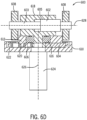
- Figure 6D is a cross-sectional side view of the axial pump assembly 600 where the axial pump assembly 600 is operatively coupled to the motor shaft 624.
- the cycloidal disk 604 of the axial pump assembly 600 can be operatively coupled to the motor shaft 624.
- Figure 6D depicts a first axis 626 about which the motor shaft 624 rotates (i.e., the longitudinal axis of the motor shaft 624) and about which the cycloidal disk 604 is arranged.
- Figure 6D also depicts a second axis 628 that is substantially perpendicular to the first axis 626 and along which the pump piston 602 moves (i.e., the longitudinal axis of the pump piston 602).
- the second axis 628 can be centered on the first axis 626 (e.g., so that the longitudinal axis of the motor shaft 624 and the longitudinal axis of the pump piston 602 substantially intersect).
- An advantage of the axial pump assembly 600 is that it combines mechanisms for reciprocation and speed reduction into a compact system. This is accomplished by combining a cam system with a cycloidal disk (i.e., cycloidal disk 604 of Figure 6A ) that also acts as a speed reducer. Further, another advantage of the axial pump assembly 600 is that a return spring is not necessary for reciprocating motion, since the points at which the pair of cam followers 608 of Figure 6A contact the second-stage cam 612 are offset from the second axis 628. Another advantage of the axial pump assembly 600 is that the cam feature being separate from the cycloidal element allows for smooth interaction but might require a central load supporting bearing. In other embodiments, more or less second-stage bushings could be used. For example, in one embodiment, no second-stage bushings might be used.
- Figure 7A illustrates an exploded view of another embodiment of an axial pump assembly 700 for driving motion of a pump piston 702.
- the axial pump assembly 700 includes a cycloidal disk 704, an eccentric bearing 706, a pair of cam follower bearings 708, and a base 710.
- a manifold 712 which can house hydraulic components (e.g., check valves) and through which hydraulic fluid can be pumped.
- Figure 7A shows the manifold 712, the manifold 712 might be considered to not be a component of the axial pump assembly 700 in some embodiments.
- the axial pump assembly 700 of Figure 7A operates similarly to the axial pump assembly 600 of Figure 6A , except the cycloidal disk 704 is integrated with a second-stage cam (e.g., second stage cam 612 of Figure 6A ).
- the cycloidal disk 704 of Figure 7A is a single component including a second-stage cam portion 714 and a geared portion 716.
- the eccentric bearing 706, the pair of cam follower bearings 708, and the base 710 can each be configured the same as their corresponding component described above with respect to Figure 6A .
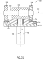
- Figure 7D is a cross-sectional side view of the axial pump assembly 700 where the axial pump assembly 700 is operatively coupled to a motor shaft 718.
- the cycloidal disk 704 of the axial pump assembly 700 can be operatively coupled to the motor shaft 718.
- Figure 7D depicts a first axis 720 about which the motor shaft 718 rotates (i.e., the longitudinal axis of the motor shaft 718) and about which the cycloidal disk 704 is arranged.
- Figure 7D also depicts a second axis 722 that is substantially perpendicular to the first axis 720 and along which the pump piston 702 moves (i.e., the longitudinal axis of the pump piston 702).
- the second axis 722 can be centered on the first axis 720 (e.g., so that the longitudinal axis of the motor shaft 718 and the longitudinal axis of the pump piston 702 substantially intersect).
- An advantage of the axial pump assembly 700 is that it combines mechanisms for reciprocation and speed reduction into a compact system requiring less parts for operation than in some existing systems. This is accomplished by combining a cam system with a cycloidal disk (i.e., cycloidal disk 704 of Figure 7A ) that also acts as a speed reducer. Further, another advantage of the axial pump assembly 700 is that a return spring is not necessary for reciprocating motion, since the points at which the pair of cam followers 708 of Figure 7A contact the second-stage cam portion 714 are offset from the second axis 722. Another advantage of the axial pump assembly 700 is that the cam feature is merged with the cycloidal element, thus eliminating the need for a central load supporting bearing.
Landscapes
- Engineering & Computer Science (AREA)
- General Engineering & Computer Science (AREA)
- Mechanical Engineering (AREA)
- Reciprocating Pumps (AREA)
Abstract
Description
- This application claims priority to
U.S. Provisional Application No. 62/875,069, filed July 17, 2019 - The present disclosure relates generally to power tools. More particularly, the present disclosure relates to axial pump designs for a hydraulic power tool.
- Hydraulic crimpers and cutters are different types of hydraulic power tools for performing work (e.g., crimping or cutting) on a workpiece. In such tools, a hydraulic tool comprising a hydraulic pump is utilized for pressurizing hydraulic fluid and transferring it to a cylinder in the tool. This cylinder causes an extendible piston to be displaced towards a cutting or crimping head. The piston exerts a force on the head of the power tool, which may typically include opposed jaws with certain cutting or crimping features, depending upon the particular configuration of the power tool. In this case, the force exerted by the piston may be used for closing the jaws to perform cutting or crimping on a workpiece (e.g., a wire) at a targeted location.
- In some known hydraulic tools, a motor can drive the hydraulic pump by way of a gear reducer or other type of gear assembly. However, there are certain perceived disadvantages to such known hydraulic tools. For example, the motor, hydraulic pump (e.g., one or more pump pistons), and gear assembly can often be complex, heavy, and bulky, particularly in hydraulic tools that are designed for high force applications. In some cases, this can increase the cost to manufacture the hydraulic tool and might make the hydraulic tool more cumbersome for an operator to use.
- Therefore, it may be useful to provide a less complex, lighter weight hydraulic tool that can be used for high force applications or lower force applications and that is also more user friendly to the operator.
- Embodiments of the invention provide a pump assembly for a hydraulic tool. In one embodiment, the pump assembly includes a reciprocating element that is configured to move between a retracted position and an extended position, a cam surface in the reciprocating element engages cam followers, a rotating element receives rotational input, and a base at least partially surrounds the rotating element. Movement of the cam followers along the cam surface moves the reciprocating element from the retracted position to the extended position.
- In some embodiments, an axial pump assembly includes a reciprocating block having ramped radial channels extending radially outward from an inner circumferential surface of the reciprocating block, a sun driver configured to be operatively coupled to a motor shaft, ball elements configured to roll on a race portion, each ball element arranged at least partially within a respective ramped radial channel of the ramped radial channels, and a base at least partially enclosing the sun driver and the ball elements. Movement of the ball elements radially outward through the ramped radial channels drives the reciprocating block away from the base. Movement of the ball elements radially inward through the ramped radial channels drives the reciprocating block toward the base.
- In some embodiments, an axial pump assembly includes a pump piston, a pair of cam follower bearings coupled to opposite ends of the pump piston, an eccentric bearing configured to drive cycloidal transmission of the pump piston, a base, and a cycloidal disk configured to be operatively coupled to a motor shaft of the hydraulic tool by way of the eccentric bearing, the cycloidal disk including a second-stage cam portion configured to transmit rotational motion to axial displacement of the pump piston. Rotation of the cycloidal disk and the second-stage cam portion pushes the pair of cam follower bearings and causes reciprocating motion of the pump piston between an extended position and a retracted position.
- The accompanying drawings, which are incorporated in and form a part of this specification, illustrate embodiments of the invention and, together with the description, serve to explain the principles of embodiments of the invention:
-
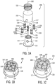
Figure 1A illustrates an exploded view of an axial pump assembly according to one embodiment of the invention. -
Figure 1B is a cross-sectional top-down view of the axial pump assembly ofFigure 1A in a retracted position. -
Figure 1C is a cross-sectional top-down view of the axial pump assembly ofFigure 1A in an extended position. -
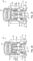
Figure 1D is a corner-sectioned view of the axial pump assembly ofFigure 1A in the retracted position. -
Figure 1E is a corner-sectioned view of the axial pump assembly ofFigure 1A in the extended position. -
Figure 1F is a cross-sectional side view of the axial pump assembly ofFigure 1A operatively coupled to a pump piston and a motor shaft. -
Figure 2A is an exploded view of an axial pump assembly according to another embodiment of the invention. -
Figure 2B is a corner-sectioned view of the axial pump assembly ofFigure 2A in a retracted position. -
Figure 2C is a corner-sectioned view of the axial pump assembly ofFigure 2A in an extended position. -
Figure 2D is a cross-sectional side view of the axial pump assembly ofFigure 2A operatively coupled to a pump piston and a gearbox. -
Figure 3A is an exploded view of an axial pump assembly according to another embodiment of the invention. -
Figure 3B is a perspective view of a bottom of a reciprocating disk of the axial pump assembly ofFigure 3A . -
Figure 3C is a cross-sectional view of the axial pump assembly ofFigure 3A in a retracted position. -
Figure 3D is a cross-sectional view of the axial pump assembly ofFigure 3A in an extended position. -
Figure 3E is a cross-sectional side view of the axial pump assembly ofFigure 3A operatively coupled to a pump piston and a motor shaft. -
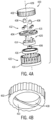
Figure 4A is an exploded view of an axial pump assembly according to another embodiment of the invention. -
Figure 4B is a perspective view of a bottom of a reciprocating disk of the axial pump assembly ofFigure 4A . -
Figure 4C is a cross-sectional view of the axial pump assembly ofFigure 4A in a retracted position. -
Figure 4D is a cross-sectional view of the axial pump assembly ofFigure 4A in an extended position. -
Figure 4E is a cross-sectional side view of the axial pump assembly ofFigure 4A operatively coupled to a pump piston and a motor shaft. -
Figure 5A is an exploded view of an axial pump assembly according to another embodiment of the invention. -
Figure 5B is a perspective view of the axial pump assembly ofFigure 5A in a retracted position. -
Figure 5C is a perspective view of the axial pump assembly ofFigure 5A in an extended position. -
Figure 5D is a cross-sectional side view of the axial pump assembly ofFigure 5A operatively coupled to a pump piston and a motor shaft. -
Figure 6A is an exploded view of an axial pump assembly according to another embodiment of the invention. -
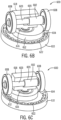
Figure 6B is a perspective view of the axial pump assembly ofFigure 6A in a retracted position. -
Figure 6C is a perspective view of the axial pump assembly ofFigure 6A in an extended position. -
Figure 6D is a cross-sectional side view of the axial pump assembly ofFigure 6A operatively coupled to a motor shaft. -
Figure 7A is an exploded view of an axial pump assembly according to another embodiment of the invention. -
Figure 7B is a perspective view of the axial pump assembly ofFigure 7A in a retracted position. -
Figure 7C is a perspective view of the axial pump assembly ofFigure 7A in an extended position. -
Figure 7D is a cross-sectional side view of the axial pump assembly ofFigure 7A operatively coupled to a motor shaft. - The following discussion is presented to enable a person skilled in the art to make and use embodiments of the invention. Various modifications to the illustrated embodiments will be readily apparent to those skilled in the art, and the generic principles herein can be applied to other embodiments and applications without departing from embodiments of the invention. Thus, embodiments of the invention are not intended to be limited to embodiments shown, but are to be accorded the widest scope consistent with the principles and features disclosed herein. The following detailed description is to be read with reference to the figures, in which like elements in different figures have like reference numerals. The figures, which are not necessarily to scale, depict selected embodiments and are not intended to limit the scope of embodiments of the invention. Skilled artisans will recognize the examples provided herein have many useful alternatives and fall within the scope of embodiments of the invention.
- As used herein, unless specified or limited otherwise, the terms "mounted," "connected," "supported," and "coupled" and variations thereof are used broadly and encompass both direct and indirect mountings, connections, supports, and couplings. Further, "connected" and "coupled" are not restricted to physical or mechanical connections or couplings.
- The disclosed axial pump assembly will be described with respect to an example hydraulic tool. However, any one or more example embodiments of the disclosed axial pump assembly could be incorporated in alternate forms of a hydraulic tool. Furthermore, one or more example embodiments of the disclosed axial pump assembly could be used outside of the context of a pump system, and could more generally be used as a mechanism or mechanisms that generate/generates reciprocation.
- In example embodiments, the disclosed axial pump assembly can be part of a transmission end of a hydraulic power tool. The transmission end of the hydraulic tool can include an electric motor configured to drive the axial pump assembly to cause a pump piston to reciprocate up and down. In practice, the movement of the pump piston can provide hydraulic fluid to a hydraulic fluid passage circuit. Specifically, as the pump piston moves down, hydraulic fluid can be withdrawn from a bladder or other device, and as the pump piston moves upward, the withdrawn fluid can be pressurized and delivered by way of the fluid passage circuit to a ram assembly of the hydraulic power tool, in order to drive a cutting or crimping head of the hydraulic power tool to perform a cutting or crimping action on a workpiece or other target.
- In example embodiments, the axial pump assembly can include a reciprocating element, such as a block, a plate, or a disk, that can be operatively coupled to the pump piston. In an alternative arrangement, the pump piston and the reciprocating element can comprise an integral component. The axial pump assembly can also include a drive element, such as a cycloidal disk or other structure, configured to drive movement of the reciprocating element. In some embodiments, the drive element can include its own internal speed reduction, eliminating the need for a gear reducer assembly. The axial pump assembly can also include one or more ball or bearing elements arranged between the drive element and the reciprocating element so that motion and force applied to the driver causes movement of the ball or bearing elements, which in turn causes movement of the reciprocating element. The axial pump assembly can also include a base that provides a housing for one or more other components of the axial pump assembly, such as the one or more ball or bearing elements and the drive element. In some embodiments, the base can be part of or inserted into a gearbox of the transmission end of the hydraulic tool.
- Each of the example embodiments of the disclosed axial pump assembly described herein generate reciprocating motion of the reciprocating element (and thus the pump piston) in a different way and provides an advantage over pump designs in existing tools. For example, the embodiments can be compact (i.e., a smaller form factor) and can reduce the quantity of components needed to achieve desired reciprocating motion. Some embodiments can include components that enable internal speed reduction, eliminating or reducing the need for an external gear reduction assembly. Additionally, in some embodiments, the reciprocating element and the drive element can be arranged, and can operate, about a common axis, and the reciprocating element and the pump piston can be substantially in line with the motor of the hydraulic tool. In other words, the axial pump assembly enables a shaft of the motor to be substantially coaxial to the line of action of the pump piston that is operatively coupled to the reciprocating element (and thus substantially coaxial to the line of action of the reciprocating element). By having components of the axial pump assembly in line with the motor, the size and complexity of the transmission end of the hydraulic tool can be reduced. In some embodiments, the pump piston can be arranged about the same common axis as the reciprocating element and the drive element. Further, in some embodiments, even more components of the axial pump assembly can be arranged about the same common axis.
-
Figure 1A illustrates anaxial pump assembly 100 that uses radial movement ofball elements 108 to drive a pump piston 118 (see, for exampleFigure 1F ). Theaxial pump assembly 100 includes areciprocating block 102, asun driver 104,planetary elements 106,ball elements 108, and abase 110. Thereciprocating block 102 can be coupled to thepump piston 118 by way of acompression spring 112, where thecompression spring 112 can be used to provide force to retract theaxial pump assembly 100. Further, thecompression spring 112 can push theaxial pump assembly 100 together, helping to hold thepump assembly 100 together. - The
reciprocating block 102 includes four rampedradial channels 114 that extend radially outward from an innercircumferential surface 113 of thereciprocating block 102. Eachchannel 114 can take the form of a through-hole or a blind hole. As a representative example, a single rampedradial channel 114 is labeled inFigure 1A . In some examples, eachchannel 114 can be ramped downward (i.e., toward thebase 110, rather than toward a top surface of thereciprocating block 102, as shown). - The
sun driver 104 is a cylindrical-shaped element that functions as a rotational input and can be operatively coupled (e.g., pressed) directly to a shaft 120 (see, for example,Figure 1 F ) of a motor of a hydraulic tool through a bottom of thebase 110. Thesun driver 104 can include arace portion 104A and a gearedportion 104B. Therace portion 104A is a portion of thesun driver 104 on whichrace portions 106A of theplanetary elements 106 roll. The gearedportion 104B is a portion of thesun driver 104 that meshes with gearedportions 106B of theplanetary elements 106, creating a planetary speed reducing system. In some embodiments, thesun driver 104 does not include arace portion 104A, but theplanetary elements 106 can still roll (i.e., rotate) around thesun driver 104 about alongitudinal axis 122 of thesun driver 104. - The
planetary elements 106 are cylindrical-shaped elements, each having arespective race portion 106A and a respective gearedportion 106B. Therace portion 106A is a portion of theplanetary element 106 on which theball elements 108 roll. The gearedportion 106B functions as a planetary gear for speed reduction. As noted above, the gearedportions 106B of theplanetary elements 106 mesh with the gear portion of thesun driver 104. Theball elements 108 can be spherical objects made of metal or another material. - The base 110 can be a housing that encircles and at least partially encloses the
sun driver 104, theplanetary elements 106, and theball elements 108. Further, acylindrical portion 109 of the base 110 can include four through-holes 116 that are each separated by a prescribed distance to space out theball elements 108. As a representative example, a single through-hole 116 is labeled inFigure 1A . An innercircumferential surface 107 of the base 110 can, in some embodiments, include a gearedportion 111 that meshes with the gearedportions 106B of theplanetary elements 106 for the purposes of speed reduction. As shown, thebase 110 has aperipheral flange 115 against which anend 117 of thereciprocating block 102 can rest or be adjacently positioned when thereciprocating block 102 is in a retracted position, as illustrated inFigures 1B and1D , for example. - Although four ramped
radial channels 114 and fourball elements 108 are shown, alternative embodiments of theaxial pump assembly 100 can include more or less of the same or similar channels and ball elements. For example, some embodiments can include two ball elements and two corresponding ramped radial channels similar to theball elements 108 and rampedradial channels 114 of theaxial pump assembly 100. - In operation, the motor rotates the
sun driver 104 within thecylindrical portion 109 of thebase 110, causing rotation of theplanetary elements 106 about the sun driver 104 (i.e., about thelongitudinal axis 122 of the axial pump assembly 100). Rotation of theplanetary elements 106 pushes theball elements 108 radially outward into the rampedradial channels 114 of thereciprocating block 102. The innercircumferential surface 113 of thereciprocating block 102 surrounds thecylindrical portion 109 of thebase 110. Theball elements 108 are pushed against the ramped surfaces within thechannels 114 at the through-holes 116, pushing thereciprocating block 102 upwards in a direction substantially parallel to thelongitudinal axis 122 and theend 117 of thereciprocating block 102 is moved away from theperipheral flange 115 of thebase 110. This motion can thus push thepump piston 118 upward. Following this motion, theball elements 108 retract radially inward within the rampedradial channels 114, toward thesun driver 104, bringing thereciprocating block 102 downwards. As arranged in the manner shown inFigure 1 A , each of theball elements 108 can move radially outward at substantially the same time as one another, and can also retract radially inward at substantially the same time as one another. In this way, the rampedradial channels 114 act as cams and theball elements 108 act as cam followers. -
Figure 1B is a cross-sectional top-down view of theaxial pump assembly 100 in the retracted position. In the retracted position, theball elements 108 are retracted into the rampedradial channels 114. In the retracted position, asingle ball element 108 can be in contact with one or moreplanetary elements 106. Theball elements 108 are positioned radially inward and proximate to one end of the rampedradial channels 114 adjacent to the innercircumferential surface 113 of theblock reciprocating block 102. Thus, thereciprocating block 102 is in a downward position and theend 117 of thereciprocating block 102 is adjacent to theperipheral flange 115 of thebase 110. Force from thecompression spring 112 can bias theaxial pump assembly 100 in the retracted position. -
Figure 1C is a cross-sectional top-down view of theaxial pump assembly 100 in an extended position. In the extended position, theball elements 108 are pushed radially outward and away from the innercircumferential surface 113 of thereciprocating block 102 and into the rampedradial channels 114. In the extended position, asingle ball element 108 is in contact with a singleplanetary element 106. As the ball elements engage the ramp of the rampedradial channels 114, thereciprocating block 102 is moved upward and theend 117 of thereciprocating block 102 is moved away from theperipheral flange 115 of thebase 110. Thus, thereciprocating block 102 is in an upward, and extended position. -
Figures 1D and1E further illustrate the relative position of theplanetary elements 106 and theball elements 108 with respect to the rampedradial channels 114.Figure 1D is a corner-sectioned view of theaxial pump assembly 100 in the retracted position.Figure 1E is a corner-sectioned view of theaxial pump assembly 100 in the extended position. -
Figure 1F is a cross-sectional side view of theaxial pump assembly 100 where theaxial pump assembly 100 is operatively coupled to thepump piston 118 and themotor shaft 120. Thesun driver 104 of theaxial pump assembly 100 can be operatively coupled to themotor shaft 120. Although a compression spring is not illustrated inFigure 1F , the schematic representation of thepump piston 118 can include both thecompression spring 112 ofFigure 1A and thepump piston 118. Further,Figure 1F illustrates theaxial pump assembly 100, thepump piston 118, and themotor shaft 120 are arranged about thelongitudinal axis 122. - An advantage of the
axial pump assembly 100 is that it combines mechanisms for reciprocation and speed reduction into a single compact system. This is accomplished by combining diameters of planetary gears (i.e., planetary elements 106) as both speed reducers and cams. Another advantage of theaxial pump assembly 100 is that one set of cam follower elements (i.e.,ball elements 108 ofFigure 1A ) drive motion that is perpendicular to the axis of the motor shaft 120 (i.e., axis 122) - namely, the radial movement of theball elements 108 ofFigure 1A - and also drive reciprocating motion that is in line with axis 122 (i.e., motion of thereciprocating block 102 ofFigure 1A and thepump piston 118 ofFigure 1F ). Further, another advantage of theaxial pump assembly 100 is that the arrangement of theaxial pump assembly 100 enables themotor shaft 120 to be coaxial to the line of action of thepump piston 118, which can help provide stable motion of thepump piston 118 during operation of the hydraulic tool, as well as reduce the space taken up by the transmission end of the hydraulic tool. - In some embodiments of the
axial pump assembly 100, components of theaxial pump assembly 100 could be configured to reverse the relationship between the motion of theball elements 108 and the motion of thereciprocating block 102. In particular, theaxial pump assembly 100 could be configured so that movement (i.e., retraction) of theball elements 108 radially inward extends thereciprocating block 102 and movement of theball elements 108 radially outward retracts thereciprocating block 102. To facilitate this, the cam feature of theaxial pump assembly 100 could be external to thereciprocating block 102. -
Figure 2A illustrates another embodiment of anaxial pump assembly 200 that, similar to theaxial pump assembly 100 shown inFigures 1A-E , uses radial movement ofball elements 208 to drive a pump piston 220 (see, for example,Figure 2D ). In particular, as shown inFigure 2A , theaxial pump assembly 200 includes areciprocating block 202, asun driver 204, a pair ofbearings 206,ball elements 208, abase 210, and a retainingring 212. A compression spring is not shown inFigure 2A , since retraction of theaxial pump assembly 200 can be achieved without the use of a compression spring. - The
ball elements 208 and the base 210 can take the same or similar forms to theball elements 108 and thebase 110 of theaxial pump assembly 100 ofFigure 1A , respectively. Although theball elements 208 are shown to include fourball elements 208, more orless ball elements 208 are possible as well. For example, twoball elements 208 can be used. - The
reciprocating block 202 includes four rampedradial channels circumferential surface 213 of thereciprocating block 202. Each channel can take the form of a through-hole or a blind hole. Within examples, two of the ramped radial channels 214- namely, a first pair of rampedradial channels 214 that are positioned radially opposite each other - can be ramped downward (i.e., toward thebase 210, rather than toward a top surface of the reciprocating block 202), whereas the other two of the ramped radial channels 216 - namely, a second pair of rampedradial channels 216 that are positioned radially opposite each other - can be ramped upward (i.e., toward a top surface of the reciprocating block 202). In some example embodiments where only twoball elements 208 are used, thereciprocating block 202 might include two rampedradial channels 214 that are positioned opposite each other, each of which might be ramped downward. - The
sun driver 204 is a partially cylindrical-shaped element that functions as a rotational input and can be operatively coupled (e.g., pressed) to a shaft 224 (see, for example,Figure 2D ) of a motor of the hydraulic tool through a bottom of thebase 210. Thesun driver 204 can be coupled directly to theshaft 224 or by way of a gearbox. Further, thesun driver 204 can include a cam groove 218 (i.e., a race or track) in which theball elements 208 roll. As such, thesun driver 204 can act as a cam. In some examples, thecam groove 218 can be sinusoidal-shaped or shaped in some other manner that coordinates the timing of the movement of the ball elements 208 - namely, so that two of theball elements 208 that are positioned radially opposite each other move radially outward at substantially the same time as the other two of theball elements 208 that are positioned radially opposite each other retract radially inward. In alternative embodiments, other groove designs and ramping arrangements for the radial channels are possible as well to achieve the same desired reciprocating movement up and down. Thesun driver 204 and itscam groove 218 drive movement of theball elements 208, but a geared driver and planetary elements are not used for speed reduction. Thus, speed reduction mechanisms that are external to theaxial pump assembly 200 might be required. - The pair of
bearings 206 can be configured to support cam forces. More orless bearings 206 could be used for the same purpose in alternative embodiments. The retainingring 212 can be configured to hold the pair ofbearings 206 axially within thebase 210. - In operation, the motor rotates the
sun driver 204, pushing two of the ball elements 208 (i.e., two radially opposing ball elements) radially outward into the first pair of rampedradial channels 214 of thereciprocating block 202 and against the ramped surfaces within the channels. This pushes thereciprocating block 202 upwards in a direction substantially parallel to thecommon axis 226 and away from aperipheral flange 215 of thebase 210. At substantially the same time as two of theball elements 208 are being pushed radially outward as part of this motion, the other two of the ball elements 208 (i.e., the other two radially opposing ball elements) retract radially inward through the second pair of rampedradial channels 216 of thereciprocating block 202 and toward thesun driver 204. This motion can thus push thepump piston 220 upward. Following this motion, the twoball elements 208 that were pushed radially outward then retract inward and, at substantially the same time, the twoball elements 208 that were retracted radially inward are then pushed radially outward, bringing thereciprocating block 202 downwards. -
Figure 2B is a corner-sectioned view of the axial pump assembly ofFigure 2A in a retracted position in which thereciprocating block 202 is in a downward position.Figure 2C is a corner-sectioned view of the axial pump assembly ofFigure 2A in an extended position in which thereciprocating block 202 is in an upward position. -
Figure 2D is a cross-sectional side view of theaxial pump assembly 200 where theaxial pump assembly 200 is operatively coupled to apump piston 220 and agearbox 222.Figure 2D also depicts amotor shaft 224 that is operatively coupled to the axial pump assembly 200 (i.e., to the sun driver 204) by way of thegearbox 222. Thegearbox 222 can also be coupled to thebase 210 of theaxial pump assembly 200. Further,Figure 2D depicts theaxis 226 about which theaxial pump assembly 200, thepump piston 220, and themotor shaft 224 are arranged. - An advantage of the
axial pump assembly 200 is that it uses one set of cam follower elements (i.e.,ball elements 208 ofFigure 2A ) to drive motion that is both perpendicular to the axis of the motor shaft 224 (i.e., axis 226) - namely, the radial movement of the ball elements 208 - and also to drive reciprocating motion that is in line with axis 226 (i.e., motion of thereciprocating block 202 ofFigure 2A and thepump piston 220 ofFigure 2D ). Another advantage of theaxial pump assembly 200 is that thecam groove 218 of thesun driver 204 enables synchronization of the perpendicular and reciprocating motions within a single compact system. Further, another advantage of theaxial pump assembly 200 is that the arrangement of theaxial pump assembly 200 enables themotor shaft 224 to be coaxial to the line of action of thepump piston 220, which can help provide stable motion of thepump piston 220 during operation of the hydraulic tool, as well as reduce the space taken up by the transmission end of the hydraulic tool. Yet another advantage of theaxial pump assembly 200 is that it has automatic retraction without the need for a compressions spring. - In some embodiments of the
axial pump assembly 200, components of theaxial pump assembly 200 could be configured to reverse the relationship between the motion of theball elements 208 and the motion of thereciprocating block 202. In particular, theaxial pump assembly 200 could be configured so that movement (i.e., retraction) of theball elements 208 radially inward extends thereciprocating block 202 and movement of theball elements 208 radially outward retracts thereciprocating block 202. To facilitate this, the cam feature of theaxial pump assembly 200 could be external to thereciprocating block 202. -
Figure 3A illustrates another embodiment of anaxial pump assembly 300 for driving motion of a pump piston 318 (see, for example,Figure 3E ). Theaxial pump assembly 300 includes areciprocating disk 302, acycloidal disk 304, aneccentric bearing 306, a pair ofball elements 308, and abase 310. In some embodiments, a compression spring (not shown) or other component can be used to bias thereciprocating disk 302 in a direction toward the pair ofball elements 308 and also to help hold theaxial pump assembly 300 together. Further, in some embodiments, additional components not shown inFigure 3A might be included to improve and maintain stability of the pair ofball elements 308. - As shown in
Figure 3B , thereciprocating disk 302 can include a firstannular cam groove 312 disposed in abottom surface 313 of thereciprocating disk 302. The pair ofball elements 308 can roll in the firstannular cam groove 312. In some examples, the firstannular cam groove 312 can be shaped to receive a portion of the pair ofball elements 308. Further, the firstannular cam groove 312 can be tapered so that the deepest portions of the firstannular cam groove 312 contact the pair ofball elements 308 at substantially the same time, causing thereciprocating disk 302 to be in a retracted position. Still further, the firstannular cam groove 312 can be tapered so that the shallowest portions of the firstannular cam groove 312 contact the pair ofball elements 308 at substantially the same time, causing thereciprocating disk 302 to be in an extended position. The retracted position is shown in the cross-sectional view of theaxial pump assembly 300 ofFigure 3C . The extended position is shown in the cross-sectional view of theaxial pump assembly 300 ofFigure 3D . - Referring back to
Figure 3A , thecycloidal disk 304 functions as a rotational input and can be operatively coupled to a shaft 320 (see, for example,Figure 3E ) of the motor of the hydraulic tool through a bottom of thebase 310. For example, thecycloidal disk 304 can be coupled to theshaft 320 by way of theshaft 320 being pressed to theeccentric bearing 306. Additionally, thecycloidal disk 304 can include a pair of through-holes 315 configured to maintain the pair ofball elements 308 in the firstannular cam groove 312, as well as in the secondannular cam groove 314 of thebase 310, and also to rotationally push the pair ofball elements 308 during operation. Further, thecycloidal disk 304 can have a gearedperiphery 317 for meshing withbase pins 316 of thebase 310. As so arranged, thecycloidal disk 304 can provide speed reduction. Thecycloidal disk 304 can also include a through-hole 319 configured to encircle theeccentric bearing 306. Theeccentric bearing 306 can be configured to generate rotational eccentricity that drives cycloidal transmission. The pair ofball elements 308 can be configured to act as cam followers that transmit axial forces between thereciprocating disk 302 and thebase 310. - The base 310 can be configured to act as housing for other components of the
axial pump assembly 300 and to provide a reaction force to drive thecycloidal disk 304. As noted above, the base 310 can include the secondannular cam groove 314 which, unlike the firstannular cam groove 312 might have a uniform depth. - In operation, rotation of the shaft rotates the
cycloidal disk 304, thus rotationally pushing the pair ofball elements 308. The movement of the pair ofball elements 308 in the firstannular cam groove 312 thus causes thereciprocating disk 302 to move up and down between the retracted position and the extended position. -
Figure 3E is a cross-sectional side view of theaxial pump assembly 300 where theaxial pump assembly 300 is operatively coupled to thepump piston 318 and themotor shaft 320. As mentioned above, thecycloidal disk 304 of theaxial pump assembly 300 can be operatively coupled to themotor shaft 320. Although a compression spring is not depicted inFigure 3E , the block representing thepump piston 318 can represent both the compression spring and thepump piston 318. Further,Figure 3E depicts anaxis 322 about which theaxial pump assembly 300, thepump piston 318, and themotor shaft 320 are arranged. - An advantage of the
axial pump assembly 300 is that it combines mechanisms for reciprocation and speed reduction into a single compact system requiring less parts for operation than in some existing systems. This is accomplished by using cam followers (i.e.,ball elements 308 ofFigure 3A ) that interact with a cam of a reciprocating element (i.e., the firstannular cam groove 312 of reciprocating disk 302). Further, another advantage of theaxial pump assembly 300 is that the arrangement of theaxial pump assembly 300 enables themotor shaft 320 to be coaxial to the line of action of thepump piston 318, which can help reduce the space taken up by the transmission end of the hydraulic tool. -
Figure 4A illustrates another embodiment of anaxial pump assembly 400 for driving motion of a pump piston 424 (see, for example,Figure 4E ). In particular, theaxial pump assembly 400 uses a tangential cam to create axial motion. Theaxial pump assembly 400 includes areciprocating disk 402, acycloidal disk 404, aneccentric bushing 406, a pair ofcam roller bushings 408, abase 410, four second-stage bushings 412, a second-stage disk 414, and abearing 416. In some embodiments, a compression spring (not shown inFigure 4A ) or other component can be used to bias thereciprocating disk 402 in a direction toward the pair ofcam roller bushings 408 and also to help hold theaxial pump assembly 400 together. - As shown in
Figure 4B , thereciprocating disk 402 can include a cam groove 418 disposed on or in an innercircumferential surface 413 of thereciprocating disk 402. By way of the cam groove 418, thereciprocating disk 402 interacts axially with the pair ofcam roller bushings 408 to create reciprocating motion of thereciprocating disk 402 between a retracted position and an extended position. The retracted position is shown in the cross-sectional view of theaxial pump assembly 400 ofFigure 4C . The extended position is shown in the cross-sectional view of theaxial pump assembly 400 ofFigure 4D . - Referring back to
Figure 4A , thecycloidal disk 404 functions as a rotational input and can be operatively coupled to a shaft 426 (see, for example,Figure 4E ) of the motor (not shown) of the hydraulic tool through a bottom of thebase 410. For example, thecycloidal disk 404 can be coupled to theshaft 426 by way of theshaft 426 being pressed to theeccentric bushing 406. Thecycloidal disk 404 can be positioned between thereciprocating disk 402 and the second-stage disk 414. Additionally, thecycloidal disk 404 can include five through-holes 415, four of which are configured to receive the four second-stage bushings 412 and fourdisk pins 420 protruding from the second-stage disk 414, and one of which is configured for receiving theeccentric bushing 406. Theeccentric bushing 406 can be configured to generate rotational eccentricity that drives cycloidal transmission. Further, thecycloidal disk 404 can have a geared periphery for meshing withbase pins 422 of thebase 410 and providing speed reduction. - As so arranged, the
cycloidal disk 404, in operation, can convert eccentric motion to rotational motion - namely, rotational motion that drives rotation of the second-stage disk 414. Each cam roller bushing of the pair ofcam roller bushings 408 can include a through-hole, a blind hole, or other manner of coupling thecam roller bushing 408 to one of the four disk pins 420. Thus, in operation, the rotational motion of the second-stage disk 414 is translated to the pair ofcam roller bushings 408, which in turn interact axially with the cam groove 418 of thereciprocating disk 402, causing thereciprocating disk 402 to move up and down between the retracted position and the extended position. - Furthermore, the four second-
stage bushings 412 can be slid around or otherwise coupled to the fourdisk pins 420 and are configured to reduce frictional resistance between the fourdisk pins 420 and thecycloidal disk 404. Similarly, the bearing 416 can encircle the second-stage disk 414 and is configured to reduce frictional resistance between the base 410 and the second-stage disk 414. The base 410 can be configured to act as housing for other components of theaxial pump assembly 400 and to provide a reaction force to drive thecycloidal disk 404. -
Figure 4E is a cross-sectional side view of theaxial pump assembly 400 where theaxial pump assembly 400 is operatively coupled to thepump piston 424 and themotor shaft 426. As mentioned above, thecycloidal disk 404 of theaxial pump assembly 400 can be operatively coupled to themotor shaft 426. Although a compression spring is not depicted inFigure 4E , the block representing thepump piston 424 can represent both the compression spring and thepump piston 424. Further,Figure 4E depicts anaxis 428 about which theaxial pump assembly 400, thepump piston 424, and themotor shaft 426 are arranged. - An advantage of the
axial pump assembly 400 is that it combines mechanisms for reciprocation and speed reduction into a single system. This is accomplished by combining a cam system with a cycloidal reducer. Further, another advantage of theaxial pump assembly 400 is that the arrangement of theaxial pump assembly 400 enables themotor shaft 426 to be coaxial to the line of action of thepump piston 424, which can help reduce the space taken up by the transmission end of the hydraulic tool and can also help maintain stable motion. - In alternative embodiments, a planetary gear system could be incorporated with the
axial pump assembly 400. In other alternative embodiments, more or less disk pins, base pins, and second-stage bushings could be used. For example, in one embodiment, no second-stage bushings might be used. -
Figure 5A illustrates an exploded view of another embodiment of anaxial pump assembly 500 for driving motion of a pump piston 524 (See, for exampleFigure 5D ). In particular, theaxial pump assembly 500 uses an axial cam to create motion. Theaxial pump assembly 500 includes areciprocating plate 502, acycloidal disk 504, aneccentric bushing 506, a pair ofcam follower bushings 508, abase 510, aring element 512, five second-stage bushings 514, and abearing 516. In some embodiments, a compression spring (not shown inFigure 5A ) or other component can be used to bias thereciprocating plate 502 in a retracted position and also to help hold theaxial pump assembly 500 together. Thereciprocating plate 502 can include two opposing side members around which the pair ofcam follower bushings 508 are positioned. - The
cycloidal disk 504 functions as a rotational input and can be operatively coupled to a shaft 526 (see, for example,Figure 5D ) of the motor (not shown) of the hydraulic tool through a bottom of thebase 510. For example, thecycloidal disk 504 can be coupled to the shaft by way of the shaft being pressed to theeccentric bushing 506. Thecycloidal disk 504 can be mounted to thebase 510 by way of fivebase pins 518 protruding from thebase 510 and can be mounted so that thecycloidal disk 504 is positioned between thereciprocating plate 502 and the bottom of thebase 510. Additionally, thecycloidal disk 504 can include six through-holes 515, five of which are configured to receive the five second-stage bushings 514 and the fivebase pins 518, and one of which is configured for receiving theeccentric bushing 506. Theeccentric bushing 506 can be configured to generate rotational eccentricity that drives cycloidal transmission. Further, thecycloidal disk 504 can have a gearedperiphery 517 for meshing withouter pins 520 of thering element 512. - In addition, the
ring element 512 can include anannular cam track 522 protruding from thering element 512 and along which the pair ofcam follower bushings 508 roll to produce reciprocating motion. Theannular cam track 522 can be tapered such that the deepest portions of theannular cam track 522 contact the pair ofcam follower bushings 508 at substantially the same time, thereby causing thereciprocating plate 502 to be in a retracted position. Further, theannular cam track 522 can be tapered such that the shallowest portions of theannular cam track 522 contact the pair ofcam follower bushings 508 at substantially the same time, causing thereciprocating plate 502 to be in an extended position. The retracted position is shown in the perspective view of theaxial pump assembly 500 ofFigure 5B . The extended position is shown in the perspective view of theaxial pump assembly 500 ofFigure 5C . - Through the meshing of the
outer pins 520 with the geared periphery of thecycloidal disk 504, thering element 512 receives rotational motion from thecycloidal disk 504. This rotational motion is then translated to reciprocating motion of thereciprocating plate 502 between the retracted position and the extended position by way of the pair ofcam follower bushings 508 rolling on theannular cam track 522. - Furthermore, the five second-
stage bushings 514 can be slid around or otherwise coupled to the fivebase pins 518 and are configured to reduce frictional resistance between the fivebase pins 518 and thecycloidal disk 504. Similarly, the bearing 516 can encircle thering element 512 and be positioned between thering element 512 and the side wall of thebase 510. Thebearing 516 is configured to reduce frictional resistance between the base 510 and thering element 512. For simplicity, thebearing 516 is not shown inFigures 5B and 5C . Moreover, the base 510 can be configured to act as housing for other components of theaxial pump assembly 500 and to provide a reaction force to drive thecycloidal disk 504 and thering element 512. - As so arranged, the
cycloidal disk 504, in operation, can convert eccentric motion to rotational motion - namely, motion that drives rotation of thering element 512. In particular, rotation of the motor shaft causes thecycloidal disk 504 to oscillate eccentrically, back and forth in a circular motion. Reaction forces between thecycloidal disk 504 and the five second-stage bushings 514 (or, in an embodiment where no bushings a present, then between thecycloidal disk 504 and the five base pins 518) cause the geared periphery of thecycloidal disk 504 to push on theouter pins 520, driving rotation of thering element 512 and, in turn, reciprocating motion of thereciprocating plate 502. -
Figure 5D is a cross-sectional side view of theaxial pump assembly 500 where theaxial pump assembly 500 is operatively coupled to thepump piston 524 and themotor shaft 526. As mentioned above, thecycloidal disk 504 of theaxial pump assembly 500 can be operatively coupled to themotor shaft 526. Although a compression spring is not depicted inFigure 5D , the block representing thepump piston 524 can represent both the compression spring and thepump piston 524. Further,Figure 5D depicts anaxis 528 about which theaxial pump assembly 500, thepump piston 524, and themotor shaft 526 are arranged. - An advantage of the
axial pump assembly 500 is that it combines mechanisms for reciprocation and speed reduction into a single system. This is accomplished by combining a cam system with a cycloidal reducer. Further, another advantage of theaxial pump assembly 500 is that the arrangement of theaxial pump assembly 500 enables themotor shaft 526 to be coaxial to the line of action of thepump piston 524, which can help reduce the space taken up by the transmission end of the hydraulic tool and can also help maintain stable motion. Theaxial pump assembly 500 also differs from some existing arrangements in that thecycloidal disk 504 oscillates eccentrically instead of rotating. - In alternative embodiments, a planetary gear system could be incorporated with the
axial pump assembly 500. In other alternative embodiments, more or less disk pins, base pins, and second-stage bushings could be used. For example, in one embodiment, no second-stage bushings might be used. -
Figures 6A-6C and7A-7C relate to another form that an axial pump assembly might take - particularly, where reciprocating motion is generated by a pump piston that is transverse to other components of the axial pump assembly and perpendicular to an axis about which a shaft of the motor (and thus, the cycloidal disk) rotates. Similar to the embodiments described above, each of the example axial pump assemblies shown inFigures 6A-6C and7A-7C are compact and combine speed reduction and reciprocating motion in a single mechanism. -
Figure 6A illustrates an exploded view of another embodiment of anaxial pump assembly 600 for driving motion of apump piston 602. In addition to thepump piston 602, theaxial pump assembly 600 includes acycloidal disk 604, aneccentric bearing 606, a pair ofcam follower bearings 608, abase 610, a second-stage cam 612 operatively coupled to thecycloidal disk 604, five second-stage bushings 614, and aload supporting bearing 616. Also shown is a manifold 618, which can house hydraulic components (e.g., check valves) and through which hydraulic fluid can be pumped. AlthoughFigure 6A shows the manifold 618, the manifold 618 might be considered to not be a component of theaxial pump assembly 600 in some embodiments. - The
pump piston 602 is bi-diametral and transverse, comprising afirst section 603 having a first diameter and asecond section 605 having a second diameter that is larger than the first diameter. The two diameters enable hydraulic fluid to be pumped through themanifold 618. Thepump piston 602 is arranged partially within themanifold 618. - The
cycloidal disk 604 functions as a rotational input and can be operatively coupled to a shaft 624 (see, for example,Figure 6D ) of the motor (not shown) of the hydraulic tool through a bottom of thebase 610. For example, thecycloidal disk 604 can be coupled to the shaft by way of the shaft being pressed to theeccentric bearing 606. Thecycloidal disk 604 can be positioned between the second-stage cam 612 and the bottom of thebase 610. Additionally, thecycloidal disk 604 can include six through-holes 615, five of which are configured to receive the five second-stage bushings 614 and fivecam pins 620 protruding from the bottom of the second-stage cam 612, and one of which is configured for receiving theeccentric bearing 606. Theeccentric bearing 606 can be configured to generate rotational eccentricity that drives cycloidal transmission. Further, thecycloidal disk 604 can have a gearedperiphery 617 for meshing withbase pins 622 of thebase 610. As so arranged, thecycloidal disk 604, in operation, provides speed reduction and can convert eccentric motion to rotational motion - namely, rotational motion that drives rotation of the second-stage cam 612. - The pair of
cam follower bearings 608 are coupled to the ends of thepump piston 602. Rotational motion of the second-stage cam 612 pushes the pair ofcam follower bearings 608, which moves thepump piston 602 back and forth between a retracted position and an extended position. The retracted position is shown in the perspective view of theaxial pump assembly 600 ofFigure 6B . The extended position is shown in the perspective view of theaxial pump assembly 600 ofFigure 6C . InFigures 6B and 6C , the manifold 618 is sectioned in order to show the position of thepump piston 602. - Furthermore, the five second-
stage bushings 614 can be slid around or otherwise coupled to the fivecam pins 620 and are configured to transmit rotational force from thecycloidal disk 604 to the second-stage cam 612. In addition, theload supporting bearing 616 can be slid around or otherwise coupled to the manifold 618 and is configured to support loads from the second-stage cam 612. -
Figure 6D is a cross-sectional side view of theaxial pump assembly 600 where theaxial pump assembly 600 is operatively coupled to themotor shaft 624. As mentioned above, thecycloidal disk 604 of theaxial pump assembly 600 can be operatively coupled to themotor shaft 624. Further,Figure 6D depicts afirst axis 626 about which themotor shaft 624 rotates (i.e., the longitudinal axis of the motor shaft 624) and about which thecycloidal disk 604 is arranged.Figure 6D also depicts asecond axis 628 that is substantially perpendicular to thefirst axis 626 and along which thepump piston 602 moves (i.e., the longitudinal axis of the pump piston 602). In some embodiments, thesecond axis 628 can be centered on the first axis 626 (e.g., so that the longitudinal axis of themotor shaft 624 and the longitudinal axis of thepump piston 602 substantially intersect). - An advantage of the
axial pump assembly 600 is that it combines mechanisms for reciprocation and speed reduction into a compact system. This is accomplished by combining a cam system with a cycloidal disk (i.e.,cycloidal disk 604 ofFigure 6A ) that also acts as a speed reducer. Further, another advantage of theaxial pump assembly 600 is that a return spring is not necessary for reciprocating motion, since the points at which the pair ofcam followers 608 ofFigure 6A contact the second-stage cam 612 are offset from thesecond axis 628. Another advantage of theaxial pump assembly 600 is that the cam feature being separate from the cycloidal element allows for smooth interaction but might require a central load supporting bearing. In other embodiments, more or less second-stage bushings could be used. For example, in one embodiment, no second-stage bushings might be used. -
Figure 7A illustrates an exploded view of another embodiment of anaxial pump assembly 700 for driving motion of apump piston 702. In addition to thepump piston 702, theaxial pump assembly 700 includes acycloidal disk 704, aneccentric bearing 706, a pair ofcam follower bearings 708, and abase 710. Also shown is a manifold 712, which can house hydraulic components (e.g., check valves) and through which hydraulic fluid can be pumped. AlthoughFigure 7A shows the manifold 712, the manifold 712 might be considered to not be a component of theaxial pump assembly 700 in some embodiments. - The
axial pump assembly 700 ofFigure 7A operates similarly to theaxial pump assembly 600 ofFigure 6A , except thecycloidal disk 704 is integrated with a second-stage cam (e.g.,second stage cam 612 ofFigure 6A ). In other words, as opposed to having two separate components - a cycloidal disk and a second-stage cam, thecycloidal disk 704 ofFigure 7A is a single component including a second-stage cam portion 714 and a gearedportion 716. Theeccentric bearing 706, the pair ofcam follower bearings 708, and the base 710 can each be configured the same as their corresponding component described above with respect toFigure 6A . - In operation, rotational motion of the second-
stage cam portion 714 of the rotatingcycloidal disk 704 pushes the pair ofcam follower bearings 708, which moves thepump piston 702 back and forth between a retracted position and an extended position. The retracted position is shown in the perspective view of theaxial pump assembly 700 ofFigure 7B . The extended position is shown in the perspective view of theaxial pump assembly 700 ofFigure 7C . InFigures 7B and 7C , the manifold 712 is sectioned in order to show the position of thepump piston 702. -
Figure 7D is a cross-sectional side view of theaxial pump assembly 700 where theaxial pump assembly 700 is operatively coupled to amotor shaft 718. As mentioned above, thecycloidal disk 704 of theaxial pump assembly 700 can be operatively coupled to themotor shaft 718. Further,Figure 7D depicts afirst axis 720 about which themotor shaft 718 rotates (i.e., the longitudinal axis of the motor shaft 718) and about which thecycloidal disk 704 is arranged.Figure 7D also depicts asecond axis 722 that is substantially perpendicular to thefirst axis 720 and along which thepump piston 702 moves (i.e., the longitudinal axis of the pump piston 702). In some embodiments, thesecond axis 722 can be centered on the first axis 720 (e.g., so that the longitudinal axis of themotor shaft 718 and the longitudinal axis of thepump piston 702 substantially intersect). - An advantage of the
axial pump assembly 700 is that it combines mechanisms for reciprocation and speed reduction into a compact system requiring less parts for operation than in some existing systems. This is accomplished by combining a cam system with a cycloidal disk (i.e.,cycloidal disk 704 ofFigure 7A ) that also acts as a speed reducer. Further, another advantage of theaxial pump assembly 700 is that a return spring is not necessary for reciprocating motion, since the points at which the pair ofcam followers 708 ofFigure 7A contact the second-stage cam portion 714 are offset from thesecond axis 722. Another advantage of theaxial pump assembly 700 is that the cam feature is merged with the cycloidal element, thus eliminating the need for a central load supporting bearing. - By the term "substantially" or "about" used herein, it is meant that the recited characteristic, parameter, value, or geometric planarity need not be achieved exactly, but that deviations or variations, including for example, tolerances, measurement error, measurement accuracy limitations and other factors known to skill in the art, may occur in amounts that do not preclude the effect the characteristic was intended to provide.
- The previous description of the disclosed embodiments is provided to enable any person skilled in the art to make or use the invention. Various modifications to these embodiments will be readily apparent to those skilled in the art, and the generic principles defined herein may be applied to other embodiments without departing from the spirit or scope of the invention. Thus, the invention is not intended to be limited to the embodiments shown herein but is to be accorded the widest scope consistent with the principles and novel features disclosed herein.
- The following clauses, which are not claims, may relate to one or more aspects or embodiments of the present invention:
- 1. A pump assembly for a hydraulic tool, the pump assembly comprising:
- a reciprocating element configured to move between a retracted position and an extended position;
- a cam surface in the reciprocating element that engages cam followers;
- a rotating element that receives a rotational input; and
- a base that at least partially surrounds the rotating element;
- movement of the cam followers along the cam surface moving the reciprocating element from the retracted position to the extended position.
- 2. The pump assembly of clause 1, wherein the reciprocating element and the rotating element are positioned along a common axis.
- 3. The pump assembly of clause 1, wherein the cam followers are balls that engage a sloped surface.
- 4. The pump assembly of clause 3, wherein the sloped surface is formed in the reciprocating element.
- 5. The pump assembly of clause 1, wherein the cam surface is a plurality of ramped channels extending radially outward from an inner circumferential surface of the reciprocating element.
- 6. The pump assembly of clause 1, wherein the rotating element is a sun driver that includes a race portion.
- 7. The pump assembly of clause 1, wherein the rotating element includes a geared portion that provides speed reduction from the rotational input.
- 8. The pump assembly of clause 1, wherein the base includes a plurality of pins extending therefrom that are dimensioned to mesh with a geared periphery of the rotating element.
- 9. The pump assembly of clause 1, wherein the reciprocating element is positioned along a first axis, the rotating element is positioned along a second axis, and the first axis is perpendicular to the second axis.
- 10. The pump assembly of clause 1, wherein the rotating element is configured to be operatively coupled to a pump piston of a hydraulic tool.
- 11. An axial pump assembly for a hydraulic tool, the axial pump assembly comprising:
- a reciprocating block having ramped radial channels extending radially outward from an inner circumferential surface of the reciprocating block;
- a sun driver configured to be operatively coupled to a motor shaft;
- ball elements configured to roll on a race portion, each ball element arranged at least partially within a respective ramped radial channel of the ramped radial channels; and
- a base at least partially enclosing the sun driver and the ball elements;
- movement of the ball elements radially outward through the ramped radial channels driving the reciprocating block away from the base, and
- movement of the ball elements radially inward through the ramped radial channels driving the reciprocating block toward the base.
- 12. The axial pump assembly of clause 11, further comprising:
planetary elements having geared portions that mesh with geared portions of the sun driver. - 13. The axial pump assembly of clause 12, wherein the ball elements are configured to roll on the race portion of each planetary element.
- 14. The axial pump assembly of clause 13, wherein the base includes a geared portion configured to mesh with the planetary elements and provide speed reduction to the axial pump assembly.
- 15. The axial pump assembly of clause 11, wherein the reciprocating block is configured to be operatively coupled to a pump piston of the hydraulic tool.
- 16. The axial pump assembly of clause 15, wherein the axial pump assembly is configured to be arranged within the hydraulic tool such that the motor shaft is substantially coaxial with a line of action of the reciprocating block.
- 17. The axial pump assembly of clause 11, wherein the race portion is a sinusoidal-shaped cam groove formed on the sun driver.
- 18. The axial pump assembly of clause 11, wherein the ramped radial channels include a first pair of opposing ramped radial channels that are ramped towards the base.
- 19. An axial pump assembly for a hydraulic tool, the axial pump comprising:
- a pump piston,
- a pair of cam follower bearings coupled to opposite ends of the pump piston;
- an eccentric bearing configured to drive cycloidal transmission of the pump piston;
- a base; and
- a cycloidal disk configured to be operatively coupled to a motor shaft of the hydraulic tool by way of the eccentric bearing, the cycloidal disk including a second-stage cam portion configured to transmit rotational motion to axial displacement of the pump piston;
- rotation of the cycloidal disk and the second-stage cam portion pushing the pair of cam follower bearings and causing reciprocating motion of the pump piston between an extended position and a retracted position.
- 20. The axial pump of clause 19, wherein the pump piston is arranged transverse to an axis about which the cycloidal disk and base are arranged, with a longitudinal axis of the pump piston substantially intersecting with the axis.
Claims (8)
- A pump assembly for a hydraulic tool, the pump assembly comprising:a reciprocating block configured to move between a retracted position and an extended position, a plurality of sloped cam surfaces formed in the reciprocating block;a plurality of cam followers, each one of the plurality of cam followers configured to engage one of the plurality of sloped cam surfaces to move the reciprocating block between the retracted position and the extended position; anda plurality of planetary elements having a race portion and a geared portion, the plurality of cam followers engaging the plurality of planetary elements at the race portion.
- The pump assembly of claim 1, further comprising a driver configured to receive a rotational input, the driver including a driving geared portion configured to engage the geared portion of the plurality of planetary elements.
- The pump assembly of claim 1, further comprising a base that at least partially surrounds each of the plurality of cam followers and the plurality of planetary elements, the base including a cylindrical portion extending axially from a peripheral flange.
- The pump assembly of claim 3, wherein the cylindrical portion defines an inner geared surface configured to mesh with the geared portion of the plurality of planetary elements.
- The pump assembly of claim 3, wherein the base includes a plurality of holes extending through the cylindrical portion, each of the plurality of holes dimensioned to allow a corresponding cam follower to pass therethrough.
- The pump assembly of claim 1, wherein the plurality of cam followers are configured as spheres.
- The pump assembly of claim 1, wherein the plurality of sloped cam surfaces are configured as channels that extend through a wall of the reciprocating block.
- The pump assembly of claim 7, wherein when the plurality of cam followers are positioned within the channels, the reciprocating block is in an extended position.
Applications Claiming Priority (3)
| Application Number | Priority Date | Filing Date | Title |
|---|---|---|---|
| US201962875069P | 2019-07-17 | 2019-07-17 | |
| PCT/US2020/042452 WO2021011843A1 (en) | 2019-07-17 | 2020-07-17 | Axial pump assemblies |
| EP20753575.8A EP3999743B1 (en) | 2019-07-17 | 2020-07-17 | Axial pump assemblies |
Related Parent Applications (1)
| Application Number | Title | Priority Date | Filing Date |
|---|---|---|---|
| EP20753575.8A Division EP3999743B1 (en) | 2019-07-17 | 2020-07-17 | Axial pump assemblies |
Publications (3)
| Publication Number | Publication Date |
|---|---|
| EP4488547A2 true EP4488547A2 (en) | 2025-01-08 |
| EP4488547A3 EP4488547A3 (en) | 2025-01-15 |
| EP4488547B1 EP4488547B1 (en) | 2026-03-25 |
Family
ID=71995116
Family Applications (2)
| Application Number | Title | Priority Date | Filing Date |
|---|---|---|---|
| EP20753575.8A Active EP3999743B1 (en) | 2019-07-17 | 2020-07-17 | Axial pump assemblies |
| EP24210850.4A Active EP4488547B1 (en) | 2019-07-17 | 2020-07-17 | Axial pump assemblies |
Family Applications Before (1)
| Application Number | Title | Priority Date | Filing Date |
|---|---|---|---|
| EP20753575.8A Active EP3999743B1 (en) | 2019-07-17 | 2020-07-17 | Axial pump assemblies |
Country Status (4)
| Country | Link |
|---|---|
| US (4) | US11421665B2 (en) |
| EP (2) | EP3999743B1 (en) |
| CN (2) | CN218293767U (en) |
| WO (1) | WO2021011843A1 (en) |
Families Citing this family (4)
| Publication number | Priority date | Publication date | Assignee | Title |
|---|---|---|---|---|
| CN218293767U (en) * | 2019-07-17 | 2023-01-13 | 米沃奇电动工具公司 | Axial pump assembly for hydraulic tool |
| US11703039B2 (en) * | 2020-08-07 | 2023-07-18 | Ridge Tool Company | Wobble plate pump drive with gear box |
| CN113236724B (en) * | 2021-05-17 | 2022-03-18 | 浙江工业大学 | Inertia force balance type three-point contact stacking rolling-linear motion transmission mechanism |
| WO2024151760A1 (en) * | 2023-01-10 | 2024-07-18 | Milwaukee Electric Tool Corporation | Balanced pump-axial piston pump |
Family Cites Families (59)
| Publication number | Priority date | Publication date | Assignee | Title |
|---|---|---|---|---|
| US2211741A (en) * | 1940-08-13 | elwell | ||
| US1367827A (en) * | 1919-06-03 | 1921-02-08 | N C L Engineering Corp | Pump |
| US1929935A (en) * | 1930-11-07 | 1933-10-10 | Rennerfelt Sven Bernhard | Spring injection fuel pump |
| US2205953A (en) * | 1939-01-18 | 1940-06-25 | Edwin S Hall | Mechanism for the interconversion of reciprocation and rotation |
| US2401794A (en) * | 1943-10-21 | 1946-06-11 | Lawrence E Pratt | Mechanical hammer |
| US2928289A (en) * | 1957-03-13 | 1960-03-15 | Arthur M Maroth | Torque converting apparatus |
| US3343424A (en) * | 1965-05-07 | 1967-09-26 | Honeywell Inc | Timing device |
| US3760676A (en) * | 1972-05-05 | 1973-09-25 | Amada Ltd Us | Unitized ram drive for a punch press |
| US3841165A (en) * | 1973-05-16 | 1974-10-15 | J Layfield | Motion converter |
| SE459437B (en) | 1987-09-10 | 1989-07-03 | Hydro Pneumatic Ab | AXIAL Piston Pump Of High Pressure Type With Cam Drive Mechanism |
| DE3903546A1 (en) | 1988-04-13 | 1989-10-26 | Franz Georg Miller | DEVICE FOR CONVERTING A ROTATIONAL MOTION INTO A LONGITUDE AND REVERSE |
| FR2708674B1 (en) * | 1993-07-30 | 1996-05-15 | Dubuis | Volumetric piston pump driven by an alternating linear movement. |
| US5727417A (en) * | 1995-09-22 | 1998-03-17 | Greenlee Textron Inc. | Portable battery powered crimper |
| WO1998027364A1 (en) | 1996-12-17 | 1998-06-25 | Jaroslav Fedor | 'butterfly converter' for interconverting reciprocating and rotary motions |
| US6506033B2 (en) * | 2000-10-26 | 2003-01-14 | Okenseiko Co., Ltd. | Miniature pump with ball-plate drive |
| DE10329007A1 (en) | 2003-06-27 | 2005-01-13 | Gustav Klauke Gmbh | Locking bolt for attaching a tool to a hydraulic pressing device |
| EP2062334A1 (en) * | 2006-09-11 | 2009-05-27 | Cembre S.p.A. | Hydraulic pressing and/or cutting tool and mechanism for converting a rotary motion into a translational oscillating motion for this tool |
| ITRE20060133A1 (en) * | 2006-11-10 | 2008-05-11 | Idromeccanica Bertolini S P A | DEVICE FOR THE TRANSFORMATION OF A ROTARY MOTORCYCLE INTO AN ALTERNATED STRAIGHT-LINE MOTORCYCLE, IN PARTICULAR FOR PUMPS, PREFERABLY OF AGRICULTURAL TYPE AND PUMP EQUIPPED WITH SUCH A DEVICE |
| WO2008113050A1 (en) | 2007-03-15 | 2008-09-18 | Milwaukee Electric Tool Corporation | Pipe cutter |
| WO2009070357A1 (en) | 2007-11-28 | 2009-06-04 | Milwaukee Electric Tool Corporation | Pipe cutter |
| US9486864B2 (en) | 2007-07-03 | 2016-11-08 | Milwaukee Electric Tool Corporation | Pipe cutter |
| GB2464851B (en) | 2007-07-03 | 2012-04-04 | Milwaukee Electric Tool Corp | Pipe cutter |
| WO2009111743A1 (en) | 2008-03-07 | 2009-09-11 | Milwaukee Electric Tool Corporation | Battery pack for use with a power tool and a non-motorized sensing tool |
| JP5158861B2 (en) * | 2008-03-11 | 2013-03-06 | Ntn株式会社 | In-wheel motor drive device |
| US8919176B2 (en) * | 2011-06-01 | 2014-12-30 | Cembre S.P.A. | Hydrodynamic tool, a hydraulic pump and a mechanism for transforming a rotary motion into an oscillating translation motion for such a tool |
| CN204573232U (en) | 2012-07-31 | 2015-08-19 | 米沃奇电动工具公司 | multi-function valve |
| US20140124231A1 (en) | 2012-11-06 | 2014-05-08 | Milwaukee Electric Tool Corporation | Electric motor for a power tool |
| CN202997812U (en) | 2012-12-28 | 2013-06-12 | 台州巨力工具有限公司 | A mechanism converting the rotation of a motor into a short-amplitude straight reciprocating motion |
| US10131042B2 (en) | 2013-10-21 | 2018-11-20 | Milwaukee Electric Tool Corporation | Adapter for power tool devices |
| US10226826B2 (en) | 2013-10-22 | 2019-03-12 | Milwaukee Electric Tool Corporation | Hydraulic power tool |
| CN207914688U (en) | 2013-10-22 | 2018-09-28 | 米沃奇电动工具公司 | Binding clip for cutting tool |
| CN107107317B (en) | 2014-10-06 | 2019-09-17 | 米沃奇电动工具公司 | Hydraulic electric tool |
| US9808851B2 (en) | 2015-04-02 | 2017-11-07 | Milwaukee Electric Tool Corporation | PEX crimping tool |
| US10000007B2 (en) | 2015-06-10 | 2018-06-19 | Milwaukee Electric Tool Corporation | PEX expanding tool |
| US10312653B2 (en) | 2015-05-06 | 2019-06-04 | Milwaukee Electric Tool Corporation | Hydraulic tool |
| EP3307453B1 (en) | 2015-06-15 | 2022-08-03 | Milwaukee Electric Tool Corporation | Hydraulic crimper tool |
| CN107921618B (en) | 2015-06-15 | 2022-10-28 | 米沃奇电动工具公司 | Electric tool communication system |
| CN207096983U (en) | 2015-06-16 | 2018-03-13 | 米沃奇电动工具公司 | The system and server of system including external equipment and server including electric tool and external equipment |
| US10128723B2 (en) | 2015-07-07 | 2018-11-13 | Milwaukee Electric Tool Corporation | Printed circuit board spacer |
| ITUB20152131A1 (en) * | 2015-07-13 | 2017-01-13 | Fondazione St Italiano Tecnologia | ROTATIONAL SPEED REDUCER |
| US10343266B2 (en) | 2015-12-10 | 2019-07-09 | Milwaukee Electric Tool Corporation | Bit holder assembly |
| EP3223389B1 (en) | 2016-03-21 | 2022-08-24 | Milwaukee Electric Tool Corporation | System and method for charging a battery pack |
| US10967442B2 (en) | 2016-06-08 | 2021-04-06 | Milwaukee Electric Tool Corporation | Tool head |
| US10428843B2 (en) | 2016-06-08 | 2019-10-01 | Milwaukee Electric Tool Corporation | Hydraulic system of a tool |
| USD805365S1 (en) | 2016-06-27 | 2017-12-19 | Milwaukee Electric Tool Corporation | Hydraulic tool |
| US10093012B2 (en) | 2016-09-23 | 2018-10-09 | Milwaukee Electric Tool Corporation | Hydraulic power tool |
| US20180085903A1 (en) | 2016-09-27 | 2018-03-29 | Milwaukee Electric Tool Corporation | Instruction indicia on jaw assembly for pex press tool |
| US10265758B2 (en) | 2016-09-30 | 2019-04-23 | Milwaukee Electric Tool Corporation | Power tool |
| US10981264B2 (en) | 2016-10-07 | 2021-04-20 | Milwaukee Electric Tool Corporation | Hydraulic power tool |
| WO2019152439A1 (en) | 2018-01-30 | 2019-08-08 | Milwaukee Electric Tool Corporation | Power tool |
| US20200055130A1 (en) | 2018-08-14 | 2020-02-20 | Milwaukee Electric Tool Corporation | Cutting Tool Head |
| US10960473B2 (en) | 2018-08-22 | 2021-03-30 | Milwaukee Electric Tool Corporation | Rebar cutting tool |
| US11110528B2 (en) | 2018-08-31 | 2021-09-07 | Milwaukee Electric Tool Corporation | Armored cable cutter with cutting blade retention |
| US11103941B2 (en) | 2018-08-31 | 2021-08-31 | Milwaukee Electric Tool Corporation | Hydraulic tool |
| US11958177B2 (en) | 2018-09-07 | 2024-04-16 | Milwaukee Electric Tool Corporation | Hydraulic piston pump for a hydraulic tool |
| EP3894137B1 (en) | 2018-12-11 | 2025-10-22 | Milwaukee Electric Tool Corporation | Power tool component position sensing |
| CN212653901U (en) | 2019-02-20 | 2021-03-05 | 米沃奇电动工具公司 | Expansion tool, working element for expanding a pipe, fitting, mandrel assembly and pipe expansion system |
| CN218293767U (en) * | 2019-07-17 | 2023-01-13 | 米沃奇电动工具公司 | Axial pump assembly for hydraulic tool |
| DE102019119658A1 (en) * | 2019-07-19 | 2021-01-21 | Pilz Gmbh & Co. Kg | Cycloid gear with torque detection device |
-
2020
- 2020-07-17 CN CN202090000824.8U patent/CN218293767U/en active Active
- 2020-07-17 EP EP20753575.8A patent/EP3999743B1/en active Active
- 2020-07-17 CN CN202223466043.8U patent/CN220791422U/en active Active
- 2020-07-17 US US16/931,637 patent/US11421665B2/en active Active
- 2020-07-17 WO PCT/US2020/042452 patent/WO2021011843A1/en not_active Ceased
- 2020-07-17 EP EP24210850.4A patent/EP4488547B1/en active Active
-
2022
- 2022-07-18 US US17/867,207 patent/US11708821B2/en active Active
-
2023
- 2023-06-08 US US18/331,679 patent/US12313046B2/en active Active
-
2025
- 2025-04-23 US US19/187,747 patent/US20250250971A1/en active Pending
Also Published As
| Publication number | Publication date |
|---|---|
| WO2021011843A1 (en) | 2021-01-21 |
| EP3999743A1 (en) | 2022-05-25 |
| CN218293767U (en) | 2023-01-13 |
| EP4488547B1 (en) | 2026-03-25 |
| US12313046B2 (en) | 2025-05-27 |
| US20230313786A1 (en) | 2023-10-05 |
| US11708821B2 (en) | 2023-07-25 |
| US20220349393A1 (en) | 2022-11-03 |
| EP3999743B1 (en) | 2024-11-06 |
| EP4488547A3 (en) | 2025-01-15 |
| US20250250971A1 (en) | 2025-08-07 |
| CN220791422U (en) | 2024-04-16 |
| US20210017968A1 (en) | 2021-01-21 |
| US11421665B2 (en) | 2022-08-23 |
Similar Documents
| Publication | Publication Date | Title |
|---|---|---|
| US12313046B2 (en) | Axial pump assemblies | |
| US4798104A (en) | Oscillatory tooth and needle gear transmitting devices | |
| CN106415069B (en) | gear unit | |
| US20110319217A1 (en) | Roller type transmission device | |
| EP2400184B1 (en) | A roller type transmission device | |
| CN104343894B (en) | Reduction transmission bearing | |
| CN111853167B (en) | Movable pin type cycloidal reducer | |
| CN113309842B (en) | Cycloidal pinwheel harmonic reducer | |
| CN103968009A (en) | Small tooth number difference transmission mechanism and reducer comprising same | |
| EP2929216A2 (en) | Strain wave gear system | |
| JP2017180769A (en) | Flexible spline for wave gear device and wave gear device using flexible spline | |
| US20250264153A1 (en) | Strain Wave Gear System | |
| RU2445529C1 (en) | Planetary transmission | |
| CN109780163B (en) | Reciprocating type cylindrical sine end face oscillating tooth speed reducer | |
| TWI815665B (en) | Wave generator, reduction mechanism and reduction motor of harmonious reducer of powder metallurgy | |
| CN212338077U (en) | Transmission assembly and reciprocating pump including the same | |
| KR20220105328A (en) | Electric cylinder having gears and roller-screws | |
| KR101213167B1 (en) | Mechanical pressing Machine | |
| CN109519351B (en) | Plunger return device for crankshaft connecting rod type radial plunger pump | |
| CN212928684U (en) | Speed reducer and power output equipment with same | |
| CN120251678A (en) | A rigid-flexible composite speed reduction mechanism with small tooth difference | |
| CN113757320A (en) | String pin wheel reducer | |
| JP2017015183A (en) | Straight line actuation machine | |
| CN204140831U (en) | Reduction case and retarder | |
| JP2018168941A (en) | Actuator |
Legal Events
| Date | Code | Title | Description |
|---|---|---|---|
| PUAI | Public reference made under article 153(3) epc to a published international application that has entered the european phase |
Free format text: ORIGINAL CODE: 0009012 |
|
| STAA | Information on the status of an ep patent application or granted ep patent |
Free format text: STATUS: THE APPLICATION HAS BEEN PUBLISHED |
|
| REG | Reference to a national code |
Ref country code: DE Ref legal event code: R079 Free format text: PREVIOUS MAIN CLASS: F16H0025120000 Ipc: F04B0009040000 Ref document number: 602020069454 Country of ref document: DE |
|
| PUAL | Search report despatched |
Free format text: ORIGINAL CODE: 0009013 |
|
| AC | Divisional application: reference to earlier application |
Ref document number: 3999743 Country of ref document: EP Kind code of ref document: P |
|
| AK | Designated contracting states |
Kind code of ref document: A2 Designated state(s): AL AT BE BG CH CY CZ DE DK EE ES FI FR GB GR HR HU IE IS IT LI LT LU LV MC MK MT NL NO PL PT RO RS SE SI SK SM TR |
|
| XX | Miscellaneous (additional remarks) |
Free format text: MISSING OR CORRECT PARTS INCLUDED UNDER RULE 56(3) OR RULE 56A(4) EPC |
|
| AK | Designated contracting states |
Kind code of ref document: A3 Designated state(s): AL AT BE BG CH CY CZ DE DK EE ES FI FR GB GR HR HU IE IS IT LI LT LU LV MC MK MT NL NO PL PT RO RS SE SI SK SM TR Free format text: MISSING OR CORRECT PARTS INCLUDED UNDER RULE 56(3) OR RULE 56A(4) EPC |
|
| RIC1 | Information provided on ipc code assigned before grant |
Ipc: F16H 25/12 20060101ALI20241210BHEP Ipc: F04B 9/04 20060101AFI20241210BHEP |
|
| STAA | Information on the status of an ep patent application or granted ep patent |
Free format text: STATUS: REQUEST FOR EXAMINATION WAS MADE |
|
| 17P | Request for examination filed |
Effective date: 20250711 |
|
| GRAP | Despatch of communication of intention to grant a patent |
Free format text: ORIGINAL CODE: EPIDOSNIGR1 |
|
| STAA | Information on the status of an ep patent application or granted ep patent |
Free format text: STATUS: GRANT OF PATENT IS INTENDED |
|
| INTG | Intention to grant announced |
Effective date: 20251015 |
|
| GRAS | Grant fee paid |
Free format text: ORIGINAL CODE: EPIDOSNIGR3 |
|
| GRAA | (expected) grant |
Free format text: ORIGINAL CODE: 0009210 |
|
| STAA | Information on the status of an ep patent application or granted ep patent |
Free format text: STATUS: THE PATENT HAS BEEN GRANTED |
|
| AC | Divisional application: reference to earlier application |
Ref document number: 3999743 Country of ref document: EP Kind code of ref document: P |
|
| AK | Designated contracting states |
Kind code of ref document: B1 Designated state(s): AL AT BE BG CH CY CZ DE DK EE ES FI FR GB GR HR HU IE IS IT LI LT LU LV MC MK MT NL NO PL PT RO RS SE SI SK SM TR |
|
| REG | Reference to a national code |
Ref country code: CH Ref legal event code: F10 Free format text: ST27 STATUS EVENT CODE: U-0-0-F10-F00 (AS PROVIDED BY THE NATIONAL OFFICE) Effective date: 20260325 Ref country code: GB Ref legal event code: FG4D |
|
| XX | Miscellaneous (additional remarks) |
Free format text: MISSING OR CORRECT PARTS INCLUDED UNDER RULE 56(3) OR RULE 56A(4) EPC |
|
| REG | Reference to a national code |
Ref country code: DE Ref legal event code: R096 Ref document number: 602020069454 Country of ref document: DE |
|
| REG | Reference to a national code |
Ref country code: IE Ref legal event code: FG4D |
|
| PG25 | Lapsed in a contracting state [announced via postgrant information from national office to epo] |
Ref country code: RS Free format text: LAPSE BECAUSE OF FAILURE TO SUBMIT A TRANSLATION OF THE DESCRIPTION OR TO PAY THE FEE WITHIN THE PRESCRIBED TIME-LIMIT Effective date: 20260625 |
|
| PG25 | Lapsed in a contracting state [announced via postgrant information from national office to epo] |
Ref country code: GR Free format text: LAPSE BECAUSE OF FAILURE TO SUBMIT A TRANSLATION OF THE DESCRIPTION OR TO PAY THE FEE WITHIN THE PRESCRIBED TIME-LIMIT Effective date: 20260626 |
|
| REG | Reference to a national code |
Ref country code: LT Ref legal event code: MG9D |
|
| PG25 | Lapsed in a contracting state [announced via postgrant information from national office to epo] |
Ref country code: LT Free format text: LAPSE BECAUSE OF FAILURE TO SUBMIT A TRANSLATION OF THE DESCRIPTION OR TO PAY THE FEE WITHIN THE PRESCRIBED TIME-LIMIT Effective date: 20260325 |
|
| PG25 | Lapsed in a contracting state [announced via postgrant information from national office to epo] |
Ref country code: NO Free format text: LAPSE BECAUSE OF FAILURE TO SUBMIT A TRANSLATION OF THE DESCRIPTION OR TO PAY THE FEE WITHIN THE PRESCRIBED TIME-LIMIT Effective date: 20260625 |
|
| PG25 | Lapsed in a contracting state [announced via postgrant information from national office to epo] |
Ref country code: FI Free format text: LAPSE BECAUSE OF FAILURE TO SUBMIT A TRANSLATION OF THE DESCRIPTION OR TO PAY THE FEE WITHIN THE PRESCRIBED TIME-LIMIT Effective date: 20260325 Ref country code: SE Free format text: LAPSE BECAUSE OF FAILURE TO SUBMIT A TRANSLATION OF THE DESCRIPTION OR TO PAY THE FEE WITHIN THE PRESCRIBED TIME-LIMIT Effective date: 20260325 |
|
| PG25 | Lapsed in a contracting state [announced via postgrant information from national office to epo] |
Ref country code: HR Free format text: LAPSE BECAUSE OF FAILURE TO SUBMIT A TRANSLATION OF THE DESCRIPTION OR TO PAY THE FEE WITHIN THE PRESCRIBED TIME-LIMIT Effective date: 20260325 |
|
| PG25 | Lapsed in a contracting state [announced via postgrant information from national office to epo] |
Ref country code: LV Free format text: LAPSE BECAUSE OF FAILURE TO SUBMIT A TRANSLATION OF THE DESCRIPTION OR TO PAY THE FEE WITHIN THE PRESCRIBED TIME-LIMIT Effective date: 20260325 |
|
| PG25 | Lapsed in a contracting state [announced via postgrant information from national office to epo] |
Ref country code: BG Free format text: LAPSE BECAUSE OF FAILURE TO SUBMIT A TRANSLATION OF THE DESCRIPTION OR TO PAY THE FEE WITHIN THE PRESCRIBED TIME-LIMIT Effective date: 20260325 |
|
| REG | Reference to a national code |
Ref country code: NL Ref legal event code: MP Effective date: 20260325 |