EP4488488A2 - Diametral expandierbare/zusammenfaltbare kolbendichtung - Google Patents
Diametral expandierbare/zusammenfaltbare kolbendichtung Download PDFInfo
- Publication number
- EP4488488A2 EP4488488A2 EP24187240.7A EP24187240A EP4488488A2 EP 4488488 A2 EP4488488 A2 EP 4488488A2 EP 24187240 A EP24187240 A EP 24187240A EP 4488488 A2 EP4488488 A2 EP 4488488A2
- Authority
- EP
- European Patent Office
- Prior art keywords
- seal
- channels
- gas turbine
- turbine engine
- shaft
- Prior art date
- Legal status (The legal status is an assumption and is not a legal conclusion. Google has not performed a legal analysis and makes no representation as to the accuracy of the status listed.)
- Pending
Links
Images

Classifications
-
- F—MECHANICAL ENGINEERING; LIGHTING; HEATING; WEAPONS; BLASTING
- F01—MACHINES OR ENGINES IN GENERAL; ENGINE PLANTS IN GENERAL; STEAM ENGINES
- F01D—NON-POSITIVE DISPLACEMENT MACHINES OR ENGINES, e.g. STEAM TURBINES
- F01D11/00—Preventing or minimising internal leakage of working-fluid, e.g. between stages
- F01D11/005—Sealing means between non relatively rotating elements
- F01D11/006—Sealing the gap between rotor blades or blades and rotor
-
- F—MECHANICAL ENGINEERING; LIGHTING; HEATING; WEAPONS; BLASTING
- F01—MACHINES OR ENGINES IN GENERAL; ENGINE PLANTS IN GENERAL; STEAM ENGINES
- F01D—NON-POSITIVE DISPLACEMENT MACHINES OR ENGINES, e.g. STEAM TURBINES
- F01D5/00—Blades; Blade-carrying members; Heating, heat-insulating, cooling or antivibration means on the blades or the members
- F01D5/02—Blade-carrying members, e.g. rotors
- F01D5/025—Fixing blade carrying members on shafts
-
- F—MECHANICAL ENGINEERING; LIGHTING; HEATING; WEAPONS; BLASTING
- F01—MACHINES OR ENGINES IN GENERAL; ENGINE PLANTS IN GENERAL; STEAM ENGINES
- F01D—NON-POSITIVE DISPLACEMENT MACHINES OR ENGINES, e.g. STEAM TURBINES
- F01D11/00—Preventing or minimising internal leakage of working-fluid, e.g. between stages
- F01D11/005—Sealing means between non relatively rotating elements
-
- F—MECHANICAL ENGINEERING; LIGHTING; HEATING; WEAPONS; BLASTING
- F16—ENGINEERING ELEMENTS AND UNITS; GENERAL MEASURES FOR PRODUCING AND MAINTAINING EFFECTIVE FUNCTIONING OF MACHINES OR INSTALLATIONS; THERMAL INSULATION IN GENERAL
- F16J—PISTONS; CYLINDERS; SEALINGS
- F16J15/00—Sealings
- F16J15/02—Sealings between relatively-stationary surfaces
- F16J15/06—Sealings between relatively-stationary surfaces with solid packing compressed between sealing surfaces
- F16J15/08—Sealings between relatively-stationary surfaces with solid packing compressed between sealing surfaces with exclusively metal packing
- F16J15/0887—Sealings between relatively-stationary surfaces with solid packing compressed between sealing surfaces with exclusively metal packing the sealing effect being obtained by elastic deformation of the packing
-
- F—MECHANICAL ENGINEERING; LIGHTING; HEATING; WEAPONS; BLASTING
- F16—ENGINEERING ELEMENTS AND UNITS; GENERAL MEASURES FOR PRODUCING AND MAINTAINING EFFECTIVE FUNCTIONING OF MACHINES OR INSTALLATIONS; THERMAL INSULATION IN GENERAL
- F16J—PISTONS; CYLINDERS; SEALINGS
- F16J15/00—Sealings
- F16J15/44—Free-space packings
- F16J15/441—Free-space packings with floating ring
-
- F—MECHANICAL ENGINEERING; LIGHTING; HEATING; WEAPONS; BLASTING
- F16—ENGINEERING ELEMENTS AND UNITS; GENERAL MEASURES FOR PRODUCING AND MAINTAINING EFFECTIVE FUNCTIONING OF MACHINES OR INSTALLATIONS; THERMAL INSULATION IN GENERAL
- F16J—PISTONS; CYLINDERS; SEALINGS
- F16J9/00—Piston-rings, e.g. non-metallic piston-rings, seats therefor; Ring sealings of similar construction
- F16J9/12—Details
- F16J9/20—Rings with special cross-section; Oil-scraping rings
- F16J9/206—One-piece oil-scraping rings
-
- F—MECHANICAL ENGINEERING; LIGHTING; HEATING; WEAPONS; BLASTING
- F01—MACHINES OR ENGINES IN GENERAL; ENGINE PLANTS IN GENERAL; STEAM ENGINES
- F01D—NON-POSITIVE DISPLACEMENT MACHINES OR ENGINES, e.g. STEAM TURBINES
- F01D5/00—Blades; Blade-carrying members; Heating, heat-insulating, cooling or antivibration means on the blades or the members
- F01D5/02—Blade-carrying members, e.g. rotors
- F01D5/06—Rotors for more than one axial stage, e.g. of drum or multiple disc type; Details thereof, e.g. shafts, shaft connections
- F01D5/066—Connecting means for joining rotor-discs or rotor-elements together, e.g. by a central bolt, by clamps
-
- F—MECHANICAL ENGINEERING; LIGHTING; HEATING; WEAPONS; BLASTING
- F05—INDEXING SCHEMES RELATING TO ENGINES OR PUMPS IN VARIOUS SUBCLASSES OF CLASSES F01-F04
- F05D—INDEXING SCHEME FOR ASPECTS RELATING TO NON-POSITIVE-DISPLACEMENT MACHINES OR ENGINES, GAS-TURBINES OR JET-PROPULSION PLANTS
- F05D2230/00—Manufacture
- F05D2230/10—Manufacture by removing material
- F05D2230/12—Manufacture by removing material by spark erosion methods
-
- F—MECHANICAL ENGINEERING; LIGHTING; HEATING; WEAPONS; BLASTING
- F05—INDEXING SCHEMES RELATING TO ENGINES OR PUMPS IN VARIOUS SUBCLASSES OF CLASSES F01-F04
- F05D—INDEXING SCHEME FOR ASPECTS RELATING TO NON-POSITIVE-DISPLACEMENT MACHINES OR ENGINES, GAS-TURBINES OR JET-PROPULSION PLANTS
- F05D2230/00—Manufacture
- F05D2230/20—Manufacture essentially without removing material
- F05D2230/22—Manufacture essentially without removing material by sintering
-
- F—MECHANICAL ENGINEERING; LIGHTING; HEATING; WEAPONS; BLASTING
- F05—INDEXING SCHEMES RELATING TO ENGINES OR PUMPS IN VARIOUS SUBCLASSES OF CLASSES F01-F04
- F05D—INDEXING SCHEME FOR ASPECTS RELATING TO NON-POSITIVE-DISPLACEMENT MACHINES OR ENGINES, GAS-TURBINES OR JET-PROPULSION PLANTS
- F05D2230/00—Manufacture
- F05D2230/20—Manufacture essentially without removing material
- F05D2230/23—Manufacture essentially without removing material by permanently joining parts together
- F05D2230/232—Manufacture essentially without removing material by permanently joining parts together by welding
- F05D2230/234—Laser welding
-
- F—MECHANICAL ENGINEERING; LIGHTING; HEATING; WEAPONS; BLASTING
- F05—INDEXING SCHEMES RELATING TO ENGINES OR PUMPS IN VARIOUS SUBCLASSES OF CLASSES F01-F04
- F05D—INDEXING SCHEME FOR ASPECTS RELATING TO NON-POSITIVE-DISPLACEMENT MACHINES OR ENGINES, GAS-TURBINES OR JET-PROPULSION PLANTS
- F05D2230/00—Manufacture
- F05D2230/30—Manufacture with deposition of material
-
- F—MECHANICAL ENGINEERING; LIGHTING; HEATING; WEAPONS; BLASTING
- F05—INDEXING SCHEMES RELATING TO ENGINES OR PUMPS IN VARIOUS SUBCLASSES OF CLASSES F01-F04
- F05D—INDEXING SCHEME FOR ASPECTS RELATING TO NON-POSITIVE-DISPLACEMENT MACHINES OR ENGINES, GAS-TURBINES OR JET-PROPULSION PLANTS
- F05D2230/00—Manufacture
- F05D2230/60—Assembly methods
- F05D2230/64—Assembly methods using positioning or alignment devices for aligning or centring, e.g. pins
- F05D2230/642—Assembly methods using positioning or alignment devices for aligning or centring, e.g. pins using maintaining alignment while permitting differential dilatation
-
- F—MECHANICAL ENGINEERING; LIGHTING; HEATING; WEAPONS; BLASTING
- F05—INDEXING SCHEMES RELATING TO ENGINES OR PUMPS IN VARIOUS SUBCLASSES OF CLASSES F01-F04
- F05D—INDEXING SCHEME FOR ASPECTS RELATING TO NON-POSITIVE-DISPLACEMENT MACHINES OR ENGINES, GAS-TURBINES OR JET-PROPULSION PLANTS
- F05D2240/00—Components
- F05D2240/55—Seals
- F05D2240/58—Piston ring seals
-
- F—MECHANICAL ENGINEERING; LIGHTING; HEATING; WEAPONS; BLASTING
- F05—INDEXING SCHEMES RELATING TO ENGINES OR PUMPS IN VARIOUS SUBCLASSES OF CLASSES F01-F04
- F05D—INDEXING SCHEME FOR ASPECTS RELATING TO NON-POSITIVE-DISPLACEMENT MACHINES OR ENGINES, GAS-TURBINES OR JET-PROPULSION PLANTS
- F05D2260/00—Function
- F05D2260/30—Retaining components in desired mutual position
- F05D2260/38—Retaining components in desired mutual position by a spring, i.e. spring loaded or biased towards a certain position
Definitions
- a gas turbine engine typically includes a fan section, a compressor section, a combustor section and a turbine section. Air entering the compressor section is compressed and delivered into the combustion section where it is mixed with fuel and ignited to generate a high-speed exhaust gas flow. The high-speed exhaust gas flow expands through the turbine section to drive the compressor and the fan section.
- the compressor section typically includes low and high pressure compressors, and the turbine section includes low and high pressure turbines.
- the high pressure turbine drives the high pressure compressor through an outer shaft to form a high spool
- the low pressure turbine drives the low pressure compressor through an inner shaft to form a low spool.
- the fan section may also be driven by the low inner shaft.
- a direct drive gas turbine engine includes a fan section driven by the low spool such that the low pressure compressor, low pressure turbine and fan section rotate at a common speed in a common direction.
- a speed reduction device such as an epicyclical gear assembly, may be utilized to drive the fan section such that the fan section may rotate at a speed different than the turbine section.
- a shaft driven by one of the turbine sections provides an input to the epicyclical gear assembly that drives the fan section at a reduced speed.
- a gas turbine engine includes a rotor that has a seal surface, and a shaft that is rotatable about an engine central axis.
- the shaft has an annular seal channel that opens to the seal surface, and a seal for sealing against the seal surface.
- the seal has channels formed therein that define a tortuous seal wall with interconnected spring ligaments such that the seal is elastically diametrically expandable for installation clearance around the shaft and, once on the shaft, elastically diametrically collapsible into the annular seal channel.
- the seal is metallic.
- the seal is a full hoop.
- the seal has first and second opposed axial faces, and the channels are axial through-channels that open at each of the first and second opposed axial faces.
- the seal has radially inner and outer faces and an annular groove that opens at the radially inner face.
- a further embodiment of any of the foregoing embodiments includes a flexible sealant disposed in the channels and the annular groove.
- the flexible sealant seals the channels with respect to flow between the first and second opposed axial faces.
- the flexible sealant includes silicone or fluoropolymer.
- the channels are unbranched.
- the channels are helical.
- the channels are branched.
- a seal for a gas turbine engine includes a metallic tortuous seal wall with interconnected spring ligaments such that the seal is elastically diametrically expandable and elastically diametrically collapsible.
- the tortuous seal wall is metallic.
- the seal has first and second opposed axial faces, and the channels are axial through-channels that open at each of the first and second opposed axial faces.
- the seal has radially inner and outer faces and an annular groove that opens at the radially inner face.
- a further embodiment of any of the foregoing embodiments includes a flexible sealant disposed in the channels and the annular groove.
- the flexible sealant seals the channels with respect to flow between the first and second opposed axial faces.
- the channels are unbranched.
- the channels are helical.
- the channels are branched.
- a method of assembling a seal into a gas turbine engine includes providing a seal as in any of the preceding embodiments, applying an expanding force to the seal to elastically diametrically expand the seal, moving the seal over a shaft and into an annular seal channel of the shaft, and then releasing the expanding force from the seal such that the seal elastically diametrically collapses into the annular seal channel.
- the present disclosure may include any one or more of the individual features disclosed above and/or below alone or in any combination thereof.
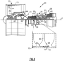
- FIG. 1 schematically illustrates a gas turbine engine 20.
- the gas turbine engine 20 is disclosed herein as a two-spool turbofan that generally incorporates a fan section 22, a compressor section 24, a combustor section 26 and a turbine section 28.
- the fan section 22 drives air along a bypass flow path B in a bypass duct defined within a housing 15 such as a fan case or nacelle, and also drives air along a core flow path C for compression and communication into the combustor section 26 then expansion through the turbine section 28.
- the exemplary engine 20 generally includes a low speed spool 30 and a high speed spool 32 mounted for rotation about an engine central longitudinal axis A relative to an engine static structure 36 via several bearing systems 38. It should be understood that various bearing systems 38 at various locations may alternatively or additionally be provided, and the location of bearing systems 38 may be varied as appropriate to the application.
- the low speed spool 30 generally includes an inner shaft 40 that interconnects, a first (or low) pressure compressor 44 and a first (or low) pressure turbine 46.
- the inner shaft 40 is connected to the fan 42 through a speed change mechanism, which in exemplary gas turbine engine 20 is illustrated as a geared architecture 48 to drive a fan 42 at a lower speed than the low speed spool 30.
- the high speed spool 32 includes an outer shaft 50 that interconnects a second (or high) pressure compressor 52 and a second (or high) pressure turbine 54.
- a combustor 56 is arranged in the exemplary gas turbine 20 between the high pressure compressor 52 and the high pressure turbine 54.
- a mid-turbine frame 57 of the engine static structure 36 may be arranged generally between the high pressure turbine 54 and the low pressure turbine 46.
- the mid-turbine frame 57 further supports bearing systems 38 in the turbine section 28.
- the inner shaft 40 and the outer shaft 50 are concentric and rotate via bearing systems 38 about the engine central longitudinal axis A which is collinear with their longitudinal axes.
- the core airflow is compressed by the low pressure compressor 44 then the high pressure compressor 52, mixed and burned with fuel in the combustor 56, then expanded through the high pressure turbine 54 and low pressure turbine 46.
- the mid-turbine frame 57 includes airfoils 59 which are in the core airflow path C.
- the turbines 46, 54 rotationally drive the respective low speed spool 30 and high speed spool 32 in response to the expansion.
- gear system 48 may be located aft of the low pressure compressor, or aft of the combustor section 26 or even aft of turbine section 28, and fan 42 may be positioned forward or aft of the location of gear system 48.
- the engine 20 in one example is a high-bypass geared aircraft engine.
- the engine 20 bypass ratio is greater than about six (6), with an example embodiment being greater than about ten (10), and can be less than or equal to about 18.0, or more narrowly can be less than or equal to 16.0.
- the geared architecture 48 is an epicyclic gear train, such as a planetary gear system or other gear system, with a gear reduction ratio of greater than about 2.3.
- the gear reduction ratio may be less than or equal to 4.0.
- the low pressure turbine 46 has a pressure ratio that is greater than about five.
- the low pressure turbine pressure ratio can be less than or equal to 13.0, or more narrowly less than or equal to 12.0.
- the engine 20 bypass ratio is greater than about ten (10:1)
- the fan diameter is significantly larger than that of the low pressure compressor 44
- the low pressure turbine 46 has a pressure ratio that is greater than about five 5:1.
- Low pressure turbine 46 pressure ratio is pressure measured prior to an inlet of low pressure turbine 46 as related to the pressure at the outlet of the low pressure turbine 46 prior to an exhaust nozzle.
- the geared architecture 48 may be an epicycle gear train, such as a planetary gear system or other gear system, with a gear reduction ratio of greater than about 2.3:1 and less than about 5:1. It should be understood, however, that the above parameters are only exemplary of one embodiment of a geared architecture engine and that the present invention is applicable to other gas turbine engines including direct drive turbofans.
- the fan section 22 of the engine 20 is designed for a particular flight condition -- typically cruise at about 0.8 Mach and about 35,000 feet (10,668 meters).
- the flight condition of 0.8 Mach and 35,000 ft (10,668 meters), with the engine at its best fuel consumption - also known as "bucket cruise Thrust Specific Fuel Consumption ('TSFC')" - is the industry standard parameter of lbm of fuel being burned divided by lbf of thrust the engine produces at that minimum point.
- 'TSFC' Thrust Specific Fuel Consumption
- “Low fan pressure ratio” is the pressure ratio across the fan blade alone, without a Fan Exit Guide Vane (“FEGV”) system.
- the low fan pressure ratio as disclosed herein according to one non-limiting embodiment is less than about 1.45, or more narrowly greater than or equal to 1.25.
- Low corrected fan tip speed is the actual fan tip speed in ft/sec divided by an industry standard temperature correction of [(Tram °R) / (518.7 °R)] 0.5 .
- the "Low corrected fan tip speed" as disclosed herein according to one non-limiting embodiment is less than about 1150.0 ft / second (350.5 meters/second), and can be greater than or equal to 1000.0 ft / second (304.8 meters/second).
- the high pressure compressor 52 includes a rotor 62 that has a bore portion 64 (shown in Fig. 1 inset).
- the rotor 62 carries rotor blades 66, which may be integral with the rotor 62 or mechanically attached to the rotor 62. It is to be understood, however, that in other examples the rotor 62 may not have blades.
- the bore portion 64 defines a seal surface 68.
- the seal surface 68 is in a central bore of the rotor 62, but it could alternatively be on a flange or arm that extends from the rotor 62.
- a shaft 70 extends through the bore.
- the shaft 70 may be part of the high speed spool 32.
- the rotor 62 and the shaft 70 are rotatable in the same direction about the engine central axis A.
- the shaft 70 defines an annular seal channel 72 that opens to the seal surface 68.
- the seal 74 may also be considered to be a piston seal.
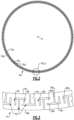
- Figure 2 illustrates an isolated view of the seal 74.
- the seal 74 is a full hoop structure.
- a "full hoop structure” is a continuous ring that has no mechanical joints.
- the seal 74 is formed of a metallic alloy, such as but not limited to, steel.
- the seal 74 defines radially inner and outer faces 74a/74b, and first and second opposed axial faces 74c/74d.
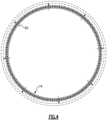
- Figure 3 illustrates a representative section of the seal 74.
- the seal 74 has channels 76 formed therein.
- the channels 76 are axial through-channels that open at each of the first and second opposed axial faces 74a/74b.
- the channels 76 define a tortuous seal wall 78 with interconnected spring ligaments 80.
- the spring ligaments 80 are elastically flexible such that the seal 74 is elastically diametrically expandable for installation clearance around the shaft 70 and, once on the shaft 70, elastically diametrically collapsible into the annular seal channel 72.
- a radial expanding force represented by radial arrows 82
- the spring ligaments 80 elastically deflect under the expanding force, allowing the sides of the channels 76 to move apart such that the channels 76 widen.
- the collective widening of the channels 76 yields a corresponding increase in the diameter of the seal 74 from its initial diameter.
- the seal 74 upon release of the expanding force will rebound to diametrically collapse to its initial diameter.
- each channel 76 initiates at either the radially inner or outer face 74a/74b and includes a first channel section 76a that extends toward the diametric centerline of the seal 74.
- the first channel section 76a splits into two branch channels 76b/76c, each extending in an opposite circumferential direction from the other.
- the branch 76b terminates and the branch 76c turns back toward the face 74a/74b at which the channel 76 initiated.
- the branches 76b of adjacent channels 76 radially overlap.
- Such a configuration creates radially- and circumferentially-oriented spring ligaments 80a/80b for a relatively more rigid elastic response.
- FIG. 5 illustrates a representative section of another seal 174 that has a different configuration.
- the channels 176 are unbranched and are helical.
- each channel 176 initiates at either the radially inner or outer face 74a/74b and includes a first channel section 176a that extends toward the diametric centerline of the seal 174 and then turns circumferentially to channel section 176b.
- Channel section 176b then turns to channel section 176c radially back toward the radially inner or outer face 74a/74b at which the channel 176 initiated.
- the channel section 176c then turns circumferentially to terminal channels section 176d.
- the channel sections 176a/176b/176c/176d thus collectively form the helical shape.
- Each helical channel 176 forms a channel pair with an adjacent channel 176 that is circumferentially oppositely oriented such that the two channels 176 in the channel pair radially overlap.
- Such a configuration creates a single radially-oriented spring ligament 180a for a relatively less rigid elastic response in comparison to the configuration of the seal 74 above.
- the number of channels 76/176, width of the channels 76/176, and spacing of the channels 76/176 may be modified along with the channel configuration to further adjust the elastic response.
Landscapes
- Engineering & Computer Science (AREA)
- General Engineering & Computer Science (AREA)
- Mechanical Engineering (AREA)
- Turbine Rotor Nozzle Sealing (AREA)
- Structures Of Non-Positive Displacement Pumps (AREA)
- Sealing Devices (AREA)
- Sealing Using Fluids, Sealing Without Contact, And Removal Of Oil (AREA)
Applications Claiming Priority (1)
| Application Number | Priority Date | Filing Date | Title |
|---|---|---|---|
| US18/348,285 US12392251B2 (en) | 2023-07-06 | 2023-07-06 | Diametrically expandable/collapsible piston seal |
Publications (2)
| Publication Number | Publication Date |
|---|---|
| EP4488488A2 true EP4488488A2 (de) | 2025-01-08 |
| EP4488488A3 EP4488488A3 (de) | 2025-03-12 |
Family
ID=91898567
Family Applications (1)
| Application Number | Title | Priority Date | Filing Date |
|---|---|---|---|
| EP24187240.7A Pending EP4488488A3 (de) | 2023-07-06 | 2024-07-08 | Diametral expandierbare/zusammenfaltbare kolbendichtung |
Country Status (2)
| Country | Link |
|---|---|
| US (1) | US12392251B2 (de) |
| EP (1) | EP4488488A3 (de) |
Family Cites Families (11)
| Publication number | Priority date | Publication date | Assignee | Title |
|---|---|---|---|---|
| US1596691A (en) | 1925-12-31 | 1926-08-17 | Simplex Piston Ring Company | Piston ring |
| US2262311A (en) * | 1939-07-13 | 1941-11-11 | Victor F Zahodiakin | Piston ring |
| FR1123357A (fr) * | 1955-03-09 | 1956-09-20 | Segment de piston à expandeur radial | |
| US3212785A (en) | 1964-01-13 | 1965-10-19 | Muskegon Piston Ring Co Inc | Oil ring |
| DE1292447B (de) * | 1966-11-26 | 1969-04-10 | Mahle Kg | OElabstreifring fuer Brennkraftmaschinenkolben |
| US3697090A (en) | 1970-06-29 | 1972-10-10 | Trw Inc | Plastics filled piston ring |
| US3735992A (en) | 1972-03-14 | 1973-05-29 | I S Prostorov | Piston ring |
| IT1121553B (it) | 1979-06-01 | 1986-04-02 | Cattaneo Leopoldo | Fasce elastiche e/o raschiaolio per motori termici e/o per tenute di qualsiasi tipo,con rigidita'periferica e deformazione in funzionamento a caldo controllata mediante intagli,fori,alleggerimenti e fessure praticati sulle superfici piane di appoggio della fascia elastica nella sede e metodi per la loro produzione |
| JP5052948B2 (ja) * | 2007-04-26 | 2012-10-17 | アネスト岩田株式会社 | ピストンリングおよびこのピストンリングを用いた流体吸排装置 |
| US11028713B2 (en) * | 2019-04-03 | 2021-06-08 | Raytheon Technologies Corporation | Rotating carbon piston ring seal |
| US11149651B2 (en) | 2019-08-07 | 2021-10-19 | Raytheon Technologies Corporation | Seal ring assembly for a gas turbine engine |
-
2023
- 2023-07-06 US US18/348,285 patent/US12392251B2/en active Active
-
2024
- 2024-07-08 EP EP24187240.7A patent/EP4488488A3/de active Pending
Also Published As
| Publication number | Publication date |
|---|---|
| US20250012197A1 (en) | 2025-01-09 |
| EP4488488A3 (de) | 2025-03-12 |
| US12392251B2 (en) | 2025-08-19 |
Similar Documents
| Publication | Publication Date | Title |
|---|---|---|
| US11125098B2 (en) | Blade outer air seal with face seal | |
| EP3677817B1 (de) | Hydrostatische dichtung mit verlängertem gehäuse | |
| EP3543469A1 (de) | Federdichtungsanordnung | |
| EP3734018A1 (de) | Dichtung für einen gasturbinenmotor | |
| US20150285152A1 (en) | Gas turbine engine and seal assembly therefore | |
| WO2015147967A1 (en) | Gas turbine engine and seal assembly therefore | |
| EP3102810B1 (de) | Umlaufende axiale segmentierte muldendichtung einer gasturbine | |
| EP3620608B1 (de) | Lageranordnung mit einem druckregulierenden dämpfer mit reduziertem axialraum und zugehöriges verfahren zur druckerhaltung in einem solchen dämpfer | |
| EP3653915A1 (de) | Hilfe zur demontage einer dichtung | |
| EP2949874A1 (de) | Doppelwandige dichtungsanordnung | |
| EP3012492A1 (de) | Gleitdichtung | |
| EP3524777B1 (de) | Hochdruckverdichterrotorpaket, zugehöriger gasturbinenmotor und verfahren zum leiten eines fluids durch ein hochdruckverdichterrotorpaket | |
| EP3680521A1 (de) | Hydrostatische dichtung mit hinterem zahn | |
| EP3660274A1 (de) | Hydrostatische dichtung mit erhöhtem designraum | |
| EP3722560B1 (de) | Hydrostatische dichtung mit strukturellem schutz durch sekundärdichtung | |
| EP3822459A1 (de) | Deckbandsegment mit kühlungsnut | |
| EP3517738B1 (de) | Schaufelaussendeckband für ein gasturbinentriebwerk | |
| EP2971578B1 (de) | Verfahren zum zusammenbau einer gasturbinentriebwerksfrontstruktur und zugehörige gasturbinentriebwerksfrontstruktur | |
| EP3816472B1 (de) | Axial steifer gekrümmter träger mit quetschdämpfer | |
| EP3282101B1 (de) | Unterlegscheibe für gasturbinenmotor | |
| EP4484712A1 (de) | Ringdichtung mit ineinander greifenden ringen | |
| EP3708773B1 (de) | Gasturbinentriebwerk mit dichtung für einen rotorstapel und zugehöriges verfahren zum abdichten einer welle gegenüber einer rotorscheibe | |
| EP4488488A2 (de) | Diametral expandierbare/zusammenfaltbare kolbendichtung | |
| EP4386179A1 (de) | Gasturbinenmotor mit geteilter spiralförmiger kolbendichtung | |
| EP3783195A1 (de) | Hitzeschild mit dämpferelement |
Legal Events
| Date | Code | Title | Description |
|---|---|---|---|
| PUAI | Public reference made under article 153(3) epc to a published international application that has entered the european phase |
Free format text: ORIGINAL CODE: 0009012 |
|
| STAA | Information on the status of an ep patent application or granted ep patent |
Free format text: STATUS: THE APPLICATION HAS BEEN PUBLISHED |
|
| AK | Designated contracting states |
Kind code of ref document: A2 Designated state(s): AL AT BE BG CH CY CZ DE DK EE ES FI FR GB GR HR HU IE IS IT LI LT LU LV MC ME MK MT NL NO PL PT RO RS SE SI SK SM TR |
|
| PUAL | Search report despatched |
Free format text: ORIGINAL CODE: 0009013 |
|
| AK | Designated contracting states |
Kind code of ref document: A3 Designated state(s): AL AT BE BG CH CY CZ DE DK EE ES FI FR GB GR HR HU IE IS IT LI LT LU LV MC ME MK MT NL NO PL PT RO RS SE SI SK SM TR |
|
| RIC1 | Information provided on ipc code assigned before grant |
Ipc: F16J 15/44 20060101ALI20250204BHEP Ipc: F16J 15/3268 20160101ALI20250204BHEP Ipc: F16J 9/20 20060101ALI20250204BHEP Ipc: F02C 7/28 20060101ALI20250204BHEP Ipc: F01D 11/00 20060101ALI20250204BHEP Ipc: F01D 5/06 20060101AFI20250204BHEP |
|
| STAA | Information on the status of an ep patent application or granted ep patent |
Free format text: STATUS: REQUEST FOR EXAMINATION WAS MADE |
|
| 17P | Request for examination filed |
Effective date: 20250912 |