EP3816472B1 - Axial steifer gekrümmter träger mit quetschdämpfer - Google Patents
Axial steifer gekrümmter träger mit quetschdämpfer Download PDFInfo
- Publication number
- EP3816472B1 EP3816472B1 EP20204670.2A EP20204670A EP3816472B1 EP 3816472 B1 EP3816472 B1 EP 3816472B1 EP 20204670 A EP20204670 A EP 20204670A EP 3816472 B1 EP3816472 B1 EP 3816472B1
- Authority
- EP
- European Patent Office
- Prior art keywords
- support structure
- curved beam
- gas turbine
- turbine engine
- component according
- Prior art date
- Legal status (The legal status is an assumption and is not a legal conclusion. Google has not performed a legal analysis and makes no representation as to the accuracy of the status listed.)
- Active
Links
Images


Classifications
-
- F—MECHANICAL ENGINEERING; LIGHTING; HEATING; WEAPONS; BLASTING
- F01—MACHINES OR ENGINES IN GENERAL; ENGINE PLANTS IN GENERAL; STEAM ENGINES
- F01D—NON-POSITIVE DISPLACEMENT MACHINES OR ENGINES, e.g. STEAM TURBINES
- F01D25/00—Component parts, details, or accessories, not provided for in, or of interest apart from, other groups
- F01D25/04—Antivibration arrangements
-
- F—MECHANICAL ENGINEERING; LIGHTING; HEATING; WEAPONS; BLASTING
- F16—ENGINEERING ELEMENTS AND UNITS; GENERAL MEASURES FOR PRODUCING AND MAINTAINING EFFECTIVE FUNCTIONING OF MACHINES OR INSTALLATIONS; THERMAL INSULATION IN GENERAL
- F16F—SPRINGS; SHOCK-ABSORBERS; MEANS FOR DAMPING VIBRATION
- F16F1/00—Springs
- F16F1/02—Springs made of steel or other material having low internal friction; Wound, torsion, leaf, cup, ring or the like springs, the material of the spring not being relevant
- F16F1/025—Springs made of steel or other material having low internal friction; Wound, torsion, leaf, cup, ring or the like springs, the material of the spring not being relevant characterised by having a particular shape
-
- F—MECHANICAL ENGINEERING; LIGHTING; HEATING; WEAPONS; BLASTING
- F01—MACHINES OR ENGINES IN GENERAL; ENGINE PLANTS IN GENERAL; STEAM ENGINES
- F01D—NON-POSITIVE DISPLACEMENT MACHINES OR ENGINES, e.g. STEAM TURBINES
- F01D25/00—Component parts, details, or accessories, not provided for in, or of interest apart from, other groups
- F01D25/16—Arrangement of bearings; Supporting or mounting bearings in casings
- F01D25/162—Bearing supports
- F01D25/164—Flexible supports; Vibration damping means associated with the bearing
-
- F—MECHANICAL ENGINEERING; LIGHTING; HEATING; WEAPONS; BLASTING
- F16—ENGINEERING ELEMENTS AND UNITS; GENERAL MEASURES FOR PRODUCING AND MAINTAINING EFFECTIVE FUNCTIONING OF MACHINES OR INSTALLATIONS; THERMAL INSULATION IN GENERAL
- F16C—SHAFTS; FLEXIBLE SHAFTS; ELEMENTS OR CRANKSHAFT MECHANISMS; ROTARY BODIES OTHER THAN GEARING ELEMENTS; BEARINGS
- F16C27/00—Elastic or yielding bearings or bearing supports, for exclusively rotary movement
- F16C27/04—Ball or roller bearings, e.g. with resilient rolling bodies
- F16C27/045—Ball or roller bearings, e.g. with resilient rolling bodies with a fluid film, e.g. squeeze film damping
-
- F—MECHANICAL ENGINEERING; LIGHTING; HEATING; WEAPONS; BLASTING
- F16—ENGINEERING ELEMENTS AND UNITS; GENERAL MEASURES FOR PRODUCING AND MAINTAINING EFFECTIVE FUNCTIONING OF MACHINES OR INSTALLATIONS; THERMAL INSULATION IN GENERAL
- F16F—SPRINGS; SHOCK-ABSORBERS; MEANS FOR DAMPING VIBRATION
- F16F15/00—Suppression of vibrations in systems; Means or arrangements for avoiding or reducing out-of-balance forces, e.g. due to motion
- F16F15/02—Suppression of vibrations of non-rotating, e.g. reciprocating systems; Suppression of vibrations of rotating systems by use of members not moving with the rotating systems
- F16F15/023—Suppression of vibrations of non-rotating, e.g. reciprocating systems; Suppression of vibrations of rotating systems by use of members not moving with the rotating systems using fluid means
- F16F15/0237—Suppression of vibrations of non-rotating, e.g. reciprocating systems; Suppression of vibrations of rotating systems by use of members not moving with the rotating systems using fluid means involving squeeze-film damping
-
- F—MECHANICAL ENGINEERING; LIGHTING; HEATING; WEAPONS; BLASTING
- F16—ENGINEERING ELEMENTS AND UNITS; GENERAL MEASURES FOR PRODUCING AND MAINTAINING EFFECTIVE FUNCTIONING OF MACHINES OR INSTALLATIONS; THERMAL INSULATION IN GENERAL
- F16F—SPRINGS; SHOCK-ABSORBERS; MEANS FOR DAMPING VIBRATION
- F16F15/00—Suppression of vibrations in systems; Means or arrangements for avoiding or reducing out-of-balance forces, e.g. due to motion
- F16F15/02—Suppression of vibrations of non-rotating, e.g. reciprocating systems; Suppression of vibrations of rotating systems by use of members not moving with the rotating systems
- F16F15/04—Suppression of vibrations of non-rotating, e.g. reciprocating systems; Suppression of vibrations of rotating systems by use of members not moving with the rotating systems using elastic means
- F16F15/06—Suppression of vibrations of non-rotating, e.g. reciprocating systems; Suppression of vibrations of rotating systems by use of members not moving with the rotating systems using elastic means with metal springs
-
- F—MECHANICAL ENGINEERING; LIGHTING; HEATING; WEAPONS; BLASTING
- F16—ENGINEERING ELEMENTS AND UNITS; GENERAL MEASURES FOR PRODUCING AND MAINTAINING EFFECTIVE FUNCTIONING OF MACHINES OR INSTALLATIONS; THERMAL INSULATION IN GENERAL
- F16F—SPRINGS; SHOCK-ABSORBERS; MEANS FOR DAMPING VIBRATION
- F16F3/00—Spring units consisting of several springs, e.g. for obtaining a desired spring characteristic
-
- F—MECHANICAL ENGINEERING; LIGHTING; HEATING; WEAPONS; BLASTING
- F05—INDEXING SCHEMES RELATING TO ENGINES OR PUMPS IN VARIOUS SUBCLASSES OF CLASSES F01-F04
- F05D—INDEXING SCHEME FOR ASPECTS RELATING TO NON-POSITIVE-DISPLACEMENT MACHINES OR ENGINES, GAS-TURBINES OR JET-PROPULSION PLANTS
- F05D2220/00—Application
- F05D2220/30—Application in turbines
- F05D2220/32—Application in turbines in gas turbines
- F05D2220/323—Application in turbines in gas turbines for aircraft propulsion, e.g. jet engines
-
- F—MECHANICAL ENGINEERING; LIGHTING; HEATING; WEAPONS; BLASTING
- F05—INDEXING SCHEMES RELATING TO ENGINES OR PUMPS IN VARIOUS SUBCLASSES OF CLASSES F01-F04
- F05D—INDEXING SCHEME FOR ASPECTS RELATING TO NON-POSITIVE-DISPLACEMENT MACHINES OR ENGINES, GAS-TURBINES OR JET-PROPULSION PLANTS
- F05D2240/00—Components
- F05D2240/50—Bearings
- F05D2240/54—Radial bearings
-
- F—MECHANICAL ENGINEERING; LIGHTING; HEATING; WEAPONS; BLASTING
- F05—INDEXING SCHEMES RELATING TO ENGINES OR PUMPS IN VARIOUS SUBCLASSES OF CLASSES F01-F04
- F05D—INDEXING SCHEME FOR ASPECTS RELATING TO NON-POSITIVE-DISPLACEMENT MACHINES OR ENGINES, GAS-TURBINES OR JET-PROPULSION PLANTS
- F05D2260/00—Function
- F05D2260/96—Preventing, counteracting or reducing vibration or noise
-
- F—MECHANICAL ENGINEERING; LIGHTING; HEATING; WEAPONS; BLASTING
- F16—ENGINEERING ELEMENTS AND UNITS; GENERAL MEASURES FOR PRODUCING AND MAINTAINING EFFECTIVE FUNCTIONING OF MACHINES OR INSTALLATIONS; THERMAL INSULATION IN GENERAL
- F16C—SHAFTS; FLEXIBLE SHAFTS; ELEMENTS OR CRANKSHAFT MECHANISMS; ROTARY BODIES OTHER THAN GEARING ELEMENTS; BEARINGS
- F16C2360/00—Engines or pumps
- F16C2360/23—Gas turbine engines
Definitions
- This application relates to a gas turbine engine that includes an axially rigid curved beam and a squeeze damper.
- a centering spring is used in combination with an oil damper that is positioned between a bearing outer race and a static engine structure.
- the oil damper comprises an oil squeeze film damper made from a plurality of segments that are mounted directly between the outer race and the engine static structure.
- the centering spring extends axially away from one end of the film damper to a distal end that is fixed to the static engine structure. While this configuration is effective at managing vibrations, a significant amount of axial space is consumed by the centering spring and damper.
- US 2016/138421 A1 discloses a rolling bearing radial support having a nonlinear stiffness.
- the bearing includes an inner race fixed for rotation with a shaft about the engine center axis, the outer race is fixed to the outer support structure, rolling elements are received between the inner and outer races, and a bearing housing surrounds the outer race to form a plurality of fluid damping chambers between the bearing housing and the outer race that are sealed by one or more piston rings or o-rings to provide the fluid damper.
- the bearing housing is supported by the engine static structure.
- the low speed spool 30 generally includes an inner shaft 40 that interconnects a first (or low) pressure compressor 44 and a first (or low) pressure turbine 46.
- the inner shaft 40 is connected to a fan 42 through a speed change mechanism, which in exemplary gas turbine engine 20 is illustrated as a geared architecture 48 to drive the fan 42 at a lower speed than the low speed spool 30.
- the high speed spool 32 includes an outer shaft 50 that interconnects a second (or high) pressure compressor 52 and a second (or high) pressure turbine 54.
- a combustor 56 is arranged in exemplary gas turbine 20 between the high pressure compressor 52 and the high pressure turbine 54.
- a mid-turbine frame 57 of the engine static structure 36 may be arranged generally between the high pressure turbine 54 and the low pressure turbine 46.
- the mid-turbine frame 57 further supports bearing systems 38 in the turbine section 28.
- the inner shaft 40 and the outer shaft 50 are concentric and rotate via bearing systems 38 about the engine central longitudinal axis A which is collinear
- the "Low corrected fan tip speed” as disclosed herein according to one non-limiting embodiment is less than about 1150 ft / second (350.5 meters/second).
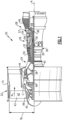
- An assembly 72 that comprises an axially rigid curved beam is installed radially outward of the bearing 60.
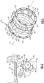
- the assembly 72 includes an outer support structure 74 fixed to the engine static structure 64, an inner support structure 76 surrounding the engine center axis A and fixed to the engine static structure 64, and a curved beam comprised of a plurality of curved beam spring segments 78 that are positioned adjacent to each other to form a ring as shown in Figure 3 .
- the inner 76 and outer 74 support structures are coupled together around the curved beam spring segments 78 of the curved beam to enclose the curved beam therebetween and form the assembly 72.
- the bearing 60 is spaced radially inward of the assembly such that there is a compartment 80 between the assembly 72 and the bearing 60.
- the outer support structure 74 is fixed to the outer race 66 and the inner support structure 76 is fixed to a flange 92 of the engine static structure 64.
- the bearing housing 84 is supported by the engine static structure 64.
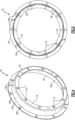
- the plurality of curved beam spring segments 78 that form a ring have an outer peripheral surface 94 and an inner peripheral surface 96 surrounding the engine center axis A.
- the plurality of curved beam spring segments 78 are circumferentially positioned adjacent to each other end-to-end to form the ring.
- the inner 76 and outer 74 support structures surround the curved beam spring segments 78 such that the outer peripheral surface 94 of the curved beam faces an inner surface 98 of the outer support structure 74 and the inner peripheral surface 96 of the curved beam faces an outer surface 100 of the inner support structure 76.
- the subject disclosure provides a configuration with a mechanical spring assembly 72 that is separated from a fluid damper 82. While the curved beam ring 114 is radially compliant, the assembly 72 also provides the capability of withstanding bilateral thrust loading.
- the ring 114 also offers the ability to tune stiffness as needed by varying the number of outer 122 and inner 124 pedestals.
- the thickness and axial width of the spring segments 78 can also be varied as needed to provide a desired stiffness.
Landscapes
- Engineering & Computer Science (AREA)
- General Engineering & Computer Science (AREA)
- Mechanical Engineering (AREA)
- Physics & Mathematics (AREA)
- Acoustics & Sound (AREA)
- Aviation & Aerospace Engineering (AREA)
- Support Of The Bearing (AREA)
Claims (15)
- Gasturbinentriebwerkskomponente, umfassend:eine innere Stützstruktur (76), die eine Triebwerksmittelachse (A) umgibt und an einer statischen Triebwerksstruktur (64) befestigt ist;eine äußere Stützstruktur (74), die radial nach außen von der inneren Stützstruktur (76) beabstandet ist;einen gekrümmten Träger, der eine Vielzahl gekrümmter Trägerfedersegmente (78) umfasst, die benachbart zueinander angeordnet sind, um einen Ring (114) zu bilden, und wobei die innere und die äußere Stützstruktur (74, 76) um den gekrümmten Träger herum miteinander gekoppelt sind, um den gekrümmten Träger dazwischen einzuschließen und eine mechanische Federbaugruppe (72) zu bilden; undein Lager (60), das radial nach innen von der mechanischen Federbaugruppe (72) beabstandet ist; undeinen Fluiddämpfer (82), der von der mechanischen Federbaugruppe (72) getrennt ist, wobei der Fluiddämpfer (82) radial nach innen von der inneren Stützstruktur (76) beabstandet ist,dadurch gekennzeichnet, dass:
die äußere Stützstruktur (74) an einem äußeren Laufring (66) des Lagers (60) befestigt ist und die innere Stützstruktur (76) an einem Flansch (92) der statischen Triebwerksstruktur (64) befestigt ist. - Gasturbinentriebwerkskomponente nach Anspruch 1, wobei das Lager (60) einen inneren Laufring (68), der zur Drehung mit einer Welle (62) um die Triebwerksmittelachse (A) befestigt ist, den äußeren Laufring (66), der an der äußeren Trägerstruktur (74) befestigt ist, Rollelemente (70), die zwischen dem inneren und dem äußeren Laufring (66, 68) aufgenommen sind, und ein Lagergehäuse (84) beinhaltet, das den äußeren Laufring (66) umgibt, um eine Vielzahl von Fluiddämpfungskammern (86) zwischen dem Lagergehäuse (84) und dem äußeren Laufring (66) zu bilden, die durch einen oder mehrere Kolbenringe oder O-Ringe (88) abgedichtet ist, um den Fluiddämpfer (82) bereitzustellen.
- Gasturbinentriebwerkskomponente nach Anspruch 2, wobei der äußere Laufring (66) an der äußeren Stützstruktur (74) montiert ist und das Lagergehäuse (84) durch den Flansch (92) der statischen Triebwerksstruktur (64) gestützt wird.
- Gasturbinentriebwerkskomponente nach einem der vorhergehenden Ansprüche, wobei der gekrümmte Träger eine äußere Umfangsfläche (94) und eine innere Umfangsfläche (96) aufweist, die die Triebwerksmittelachse (A) umgeben, und wobei die Vielzahl von gekrümmten Trägerfedersegmenten (78) in Umfangsrichtung benachbart zueinander angeordnet ist, um den Ring (114) zu bilden, und wobei die innere und die äußere Stützstruktur (74, 76) den gekrümmten Träger derart umgeben, dass die äußere Umfangsfläche (94) des gekrümmten Trägers einer inneren Fläche (98) der äußeren Stützstruktur (74) zugewandt ist und die innere Umfangsfläche (96) des gekrümmten Trägers einer äußeren Fläche (100) der inneren Stützstruktur (76) zugewandt ist.
- Gasturbinentriebwerkskomponente nach einem der vorhergehenden Ansprüche, wobei die äußere Stützstruktur (74) eine erste ringförmige Struktur mit einem ersten Satz von Laschen (134) und einem ersten Satz von Schlitzen (136) umfasst, und wobei die innere Stützstruktur (76) eine zweite ringförmige Struktur mit einem zweiten Satz von Laschen (144) und einem zweiten Satz von Schlitzen (146) umfasst, und wobei die innere und die äußere Struktur durch Einführen des zweiten Satzes von Laschen (144) durch den ersten Satz von Schlitzen (136) und durch Einführen des ersten Satzes von Laschen (134) durch den zweiten Satz von Schlitzen (146) miteinander gekoppelt werden.
- Gasturbinentriebwerkskomponente nach einem der vorhergehenden Ansprüche, wobei die Vielzahl von gekrümmten Trägerfedersegmenten (78) mindestens 10 Segmente umfasst.
- Gasturbinentriebwerkskomponente nach Anspruch 1, wobei der Fluiddämpfer (82) einen dem Lager (60) zugeordneten Quetschfilmdämpfer (82) umfasst.
- Gasturbinentriebwerkskomponente nach Anspruch 7, wobei das Lager (60) einen inneren Laufring (68), der zur Drehung mit einer Welle (62) um die Triebwerksmittelachse (A) befestigt ist, einen äußeren Laufring (66), der an der äußeren Trägerstruktur (74) befestigt ist, Rollelemente (70), die zwischen dem inneren und dem äußeren Laufring (66) aufgenommen sind, und ein Lagergehäuse (84) beinhaltet, das den äußeren Laufring (66) umgibt, um eine Vielzahl von Fluiddämpfungskammern (86) zwischen dem Lagergehäuse (84) und dem äußeren Laufring (66) zu bilden, die durch einen oder mehrere Kolbenringe oder O-Ringe (88) abgedichtet ist, um den Quetschfilmdämpfer (82) bereitzustellen.
- Gasturbinentriebwerkskomponente nach Anspruch 8, wobei das Lagergehäuse (84) durch die statische Triebwerksstruktur (64) gestützt wird.
- Gasturbinentriebwerkskomponente nach Anspruch 8 oder 9, wobei eine äußere Fläche des Lagergehäuses (84) radial mit der mechanischen Federbaugruppe (72) ausgerichtet und durch einen Spalt (80) von dieser beabstandet ist.
- Gasturbinentriebwerkskomponente nach einem der Ansprüche 7 bis 10, wobei die äußere Stützstruktur (74) eine erste ringförmige Struktur mit einem ersten Satz von Laschen (134) und einem ersten Satz von Schlitzen (136) umfasst, und wobei die innere Stützstruktur (76) eine zweite ringförmige Struktur mit einem zweiten Satz von Laschen (144) und einem zweiten Satz von Schlitzen (146) umfasst, und wobei die innere und die äußere Struktur durch Einführen des zweiten Satzes von Laschen (144) durch den ersten Satz von Schlitzen (136) und durch Einführen des ersten Satzes von Laschen (134) durch den zweiten Satz von Schlitzen (146) miteinander gekoppelt werden.
- Gasturbinentriebwerkskomponente nach Anspruch 11, wobei der gekrümmte Träger eine äußere Umfangsfläche (94) und eine innere Umfangsfläche (96) aufweist, die die Triebwerksmittelachse (A) umgeben, und wobei die Vielzahl von gekrümmten Trägerfedersegmenten (78) in Umfangsrichtung benachbart zueinander angeordnet ist, um den Ring (114) zu bilden, und wobei die innere und die äußere Stützstruktur (74, 76) den gekrümmten Träger derart umgeben, dass die äußere Umfangsfläche (94) des gekrümmten Trägers der ersten ringförmigen Struktur zugewandt ist und die innere Umfangsfläche (96) des gekrümmten Trägers der zweiten ringförmigen Struktur zugewandt ist.
- Gasturbinentriebwerkskomponente nach einem der Ansprüche 7 bis 12, wobei die äußere Stützstruktur (74) an einem/dem äußeren Laufring (66) befestigt ist und die innere Stützstruktur (76) an einem Flansch (92) der statischen Triebwerksstruktur (64) befestigt ist, und wobei optional die äußere Stützstruktur (74) eine erste Montageschnittstelle beinhaltet, die an einem/dem äußeren Laufring (66) angebracht ist, und die innere Stützstruktur (76) eine zweite Montageschnittstelle beinhaltet, die an dem Flansch (92) angebracht ist.
- Gasturbinentriebwerkskomponente nach einem der vorhergehenden Ansprüche, wobei jedes gekrümmte Trägerfedersegment (78) einen bogenförmigen Körper (120) beinhaltet, der mindestens einen äußeren Dämpfersockel (122), der sich radial nach außen von einer äußeren Umfangsfläche (94) des bogenförmigen Körpers (120) erstreckt, und mindestens einen inneren Dämpfersockel (124), der sich radial nach innen von einer inneren Umfangsfläche (96) des bogenförmigen Körpers (120) erstreckt, aufweist, und wobei der äußere Dämpfersockel (122) mit der äußeren Stützstruktur (74) in Eingriff bringbar ist und der innere Dämpfersockel (124) mit der inneren Stützstruktur (76) in Eingriff bringbar ist.
- Gasturbinentriebwerkskomponente nach Anspruch 14, wobei sich jeder bogenförmige Körper (120) in Umfangsrichtung von einem ersten Ende (126) zu einem dem ersten Ende (126) gegenüberliegenden zweiten Ende (128) erstreckt, und wobei der mindestens eine äußere Dämpfersockel (122) mittig zwischen dem ersten und dem zweiten Ende (126, 128) angeordnet ist, und wobei der mindestens eine innere Dämpfersockel (124) mindestens einen ersten inneren Dämpfersockel (124) benachbart zu dem ersten Ende (126) und einen zweiten inneren Dämpfersockel (124) benachbart zu dem zweiten Ende (128) umfasst.
Applications Claiming Priority (1)
| Application Number | Priority Date | Filing Date | Title |
|---|---|---|---|
| US16/668,786 US11466588B2 (en) | 2019-10-30 | 2019-10-30 | Axially rigid curved beam with squeeze damper |
Publications (2)
| Publication Number | Publication Date |
|---|---|
| EP3816472A1 EP3816472A1 (de) | 2021-05-05 |
| EP3816472B1 true EP3816472B1 (de) | 2025-04-16 |
Family
ID=73039880
Family Applications (1)
| Application Number | Title | Priority Date | Filing Date |
|---|---|---|---|
| EP20204670.2A Active EP3816472B1 (de) | 2019-10-30 | 2020-10-29 | Axial steifer gekrümmter träger mit quetschdämpfer |
Country Status (2)
| Country | Link |
|---|---|
| US (1) | US11466588B2 (de) |
| EP (1) | EP3816472B1 (de) |
Families Citing this family (2)
| Publication number | Priority date | Publication date | Assignee | Title |
|---|---|---|---|---|
| FR3088672B1 (fr) * | 2018-11-16 | 2020-12-18 | Safran Aircraft Engines | Dispositif pour le centrage et le guidage en rotation d'une piece rotative avec bras entrelaces |
| US12025017B2 (en) | 2022-02-02 | 2024-07-02 | Pratt & Whitney Canada Corp. | Loaded bearing system |
Citations (1)
| Publication number | Priority date | Publication date | Assignee | Title |
|---|---|---|---|---|
| US4981415A (en) * | 1989-08-16 | 1991-01-01 | United Technologies Corporation | Support for oil film dampers |
Family Cites Families (17)
| Publication number | Priority date | Publication date | Assignee | Title |
|---|---|---|---|---|
| US4213661A (en) | 1978-05-08 | 1980-07-22 | United Technologies Corporation | Bearing support structure combining fluid damping and spring damping apparatus |
| US4952076A (en) * | 1989-07-21 | 1990-08-28 | United Technologies Corporation | Fluid damper for thrust bearing |
| US4992024A (en) | 1989-12-13 | 1991-02-12 | Allied-Signal Inc. | Multi-film fluid bearing damper |
| US7104693B2 (en) | 2004-06-28 | 2006-09-12 | Honeywell International, Inc. | Multi-thickness film layer bearing cartridge and housing |
| US20060204153A1 (en) | 2005-03-10 | 2006-09-14 | Honeywell International Inc. | Compact resilient anisotropic support for bearing |
| US7648278B2 (en) * | 2007-01-05 | 2010-01-19 | Honeywell International Inc. | High speed aerospace generator resilient mount, combined centering spring and squeeze film damper |
| US8202003B2 (en) * | 2009-04-29 | 2012-06-19 | Rolls-Royce North American Technologies, Inc. | Compliant spherical bearing mount |
| US8727699B2 (en) * | 2009-12-29 | 2014-05-20 | Rolls-Royce Corporation | Rotating machinery with damping system |
| EP2524148A4 (de) | 2010-01-15 | 2015-07-08 | Dresser Rand Co | Lageranordnungshalterung und einstellungssystem |
| US8747054B2 (en) * | 2011-01-24 | 2014-06-10 | United Technologies Corporation | Bearing system for gas turbine engine |
| DE102011081200A1 (de) | 2011-08-18 | 2013-02-21 | Bosch Mahle Turbo Systems Gmbh & Co. Kg | Wälzlageranordnung eines Abgasturboladers |
| FR3003301B1 (fr) * | 2013-03-14 | 2018-01-05 | Safran Helicopter Engines | Anneau de turbine pour turbomachine |
| WO2014204633A1 (en) * | 2013-06-21 | 2014-12-24 | United Technologies Corporation | Nonlinear rolling bearing radial support stiffness |
| US9933017B2 (en) * | 2013-12-20 | 2018-04-03 | United Technologies Corporation | Bearing supports |
| WO2015186524A1 (ja) | 2014-06-02 | 2015-12-10 | 株式会社Ihi | 軸受構造、および、過給機 |
| US9745992B2 (en) | 2015-08-30 | 2017-08-29 | Honeywell International Inc. | Turbocharger bearing damper assembly |
| US10495144B1 (en) * | 2018-05-25 | 2019-12-03 | Borgwarner Inc. | Single-row ball bearing with integrated squeeze-film damper |
-
2019
- 2019-10-30 US US16/668,786 patent/US11466588B2/en active Active
-
2020
- 2020-10-29 EP EP20204670.2A patent/EP3816472B1/de active Active
Patent Citations (1)
| Publication number | Priority date | Publication date | Assignee | Title |
|---|---|---|---|---|
| US4981415A (en) * | 1989-08-16 | 1991-01-01 | United Technologies Corporation | Support for oil film dampers |
Also Published As
| Publication number | Publication date |
|---|---|
| EP3816472A1 (de) | 2021-05-05 |
| US20210131304A1 (en) | 2021-05-06 |
| US11466588B2 (en) | 2022-10-11 |
Similar Documents
| Publication | Publication Date | Title |
|---|---|---|
| EP3036417B1 (de) | Lagersystem für gasturbinenmotor | |
| EP2944774B1 (de) | Gasturbinenmotor mit fluiddämpfer | |
| EP3620608B1 (de) | Lageranordnung mit einem druckregulierenden dämpfer mit reduziertem axialraum und zugehöriges verfahren zur druckerhaltung in einem solchen dämpfer | |
| US9546560B2 (en) | Compact double grounded mechanical carbon seal | |
| US10746049B2 (en) | Gas turbine engine case including bearing compartment | |
| EP3825532B1 (de) | Getriebearchitektur für einen gasturbinenmotor | |
| EP3650721B1 (de) | Zentrierfeder für einen gasturbinenmotorlagerraum | |
| US11415064B2 (en) | Geared architecture for gas turbine engine | |
| EP3816472B1 (de) | Axial steifer gekrümmter träger mit quetschdämpfer | |
| EP2900942B1 (de) | Hitzeschild für einen mittelturbinenrahmen | |
| EP3835606B1 (de) | Feder zur zentrierung eines gekrümmten trägers für ein drucklager | |
| EP3282101B1 (de) | Unterlegscheibe für gasturbinenmotor | |
| EP3825575B1 (de) | Getriebearchitektur für einen gasturbinenmotor | |
| EP3708773B1 (de) | Gasturbinentriebwerk mit dichtung für einen rotorstapel und zugehöriges verfahren zum abdichten einer welle gegenüber einer rotorscheibe | |
| US11371375B2 (en) | Heatshield with damper member | |
| EP3957832B1 (de) | Integraler zahnradträger und lagerdämpfersockel eines gasturbinentriebwerks | |
| EP3933170B1 (de) | Mittig montierte hülsenanordnung | |
| EP3760841B1 (de) | Mehrzweckdrehsicherungssperrbolzen | |
| EP3816410B1 (de) | Einteiliger gekrümmter balkenlagerdämpfer | |
| EP3073060B1 (de) | Dichtungshalterungsstrukturen für turbomaschinen | |
| US12392251B2 (en) | Diametrically expandable/collapsible piston seal |
Legal Events
| Date | Code | Title | Description |
|---|---|---|---|
| PUAI | Public reference made under article 153(3) epc to a published international application that has entered the european phase |
Free format text: ORIGINAL CODE: 0009012 |
|
| STAA | Information on the status of an ep patent application or granted ep patent |
Free format text: STATUS: THE APPLICATION HAS BEEN PUBLISHED |
|
| AK | Designated contracting states |
Kind code of ref document: A1 Designated state(s): AL AT BE BG CH CY CZ DE DK EE ES FI FR GB GR HR HU IE IS IT LI LT LU LV MC MK MT NL NO PL PT RO RS SE SI SK SM TR |
|
| STAA | Information on the status of an ep patent application or granted ep patent |
Free format text: STATUS: REQUEST FOR EXAMINATION WAS MADE |
|
| 17P | Request for examination filed |
Effective date: 20211104 |
|
| RBV | Designated contracting states (corrected) |
Designated state(s): AL AT BE BG CH CY CZ DE DK EE ES FI FR GB GR HR HU IE IS IT LI LT LU LV MC MK MT NL NO PL PT RO RS SE SI SK SM TR |
|
| STAA | Information on the status of an ep patent application or granted ep patent |
Free format text: STATUS: EXAMINATION IS IN PROGRESS |
|
| 17Q | First examination report despatched |
Effective date: 20230301 |
|
| RAP3 | Party data changed (applicant data changed or rights of an application transferred) |
Owner name: RTX CORPORATION |
|
| GRAP | Despatch of communication of intention to grant a patent |
Free format text: ORIGINAL CODE: EPIDOSNIGR1 |
|
| STAA | Information on the status of an ep patent application or granted ep patent |
Free format text: STATUS: GRANT OF PATENT IS INTENDED |
|
| INTG | Intention to grant announced |
Effective date: 20241113 |
|
| GRAS | Grant fee paid |
Free format text: ORIGINAL CODE: EPIDOSNIGR3 |
|
| GRAA | (expected) grant |
Free format text: ORIGINAL CODE: 0009210 |
|
| STAA | Information on the status of an ep patent application or granted ep patent |
Free format text: STATUS: THE PATENT HAS BEEN GRANTED |
|
| AK | Designated contracting states |
Kind code of ref document: B1 Designated state(s): AL AT BE BG CH CY CZ DE DK EE ES FI FR GB GR HR HU IE IS IT LI LT LU LV MC MK MT NL NO PL PT RO RS SE SI SK SM TR |
|
| REG | Reference to a national code |
Ref country code: GB Ref legal event code: FG4D |
|
| REG | Reference to a national code |
Ref country code: CH Ref legal event code: EP |
|
| REG | Reference to a national code |
Ref country code: IE Ref legal event code: FG4D |
|
| REG | Reference to a national code |
Ref country code: DE Ref legal event code: R096 Ref document number: 602020049469 Country of ref document: DE |
|
| REG | Reference to a national code |
Ref country code: NL Ref legal event code: MP Effective date: 20250416 |
|
| PG25 | Lapsed in a contracting state [announced via postgrant information from national office to epo] |
Ref country code: NL Free format text: LAPSE BECAUSE OF FAILURE TO SUBMIT A TRANSLATION OF THE DESCRIPTION OR TO PAY THE FEE WITHIN THE PRESCRIBED TIME-LIMIT Effective date: 20250416 |
|
| REG | Reference to a national code |
Ref country code: AT Ref legal event code: MK05 Ref document number: 1785871 Country of ref document: AT Kind code of ref document: T Effective date: 20250416 |
|
| PG25 | Lapsed in a contracting state [announced via postgrant information from national office to epo] |
Ref country code: FI Free format text: LAPSE BECAUSE OF FAILURE TO SUBMIT A TRANSLATION OF THE DESCRIPTION OR TO PAY THE FEE WITHIN THE PRESCRIBED TIME-LIMIT Effective date: 20250416 Ref country code: PT Free format text: LAPSE BECAUSE OF FAILURE TO SUBMIT A TRANSLATION OF THE DESCRIPTION OR TO PAY THE FEE WITHIN THE PRESCRIBED TIME-LIMIT Effective date: 20250818 Ref country code: ES Free format text: LAPSE BECAUSE OF FAILURE TO SUBMIT A TRANSLATION OF THE DESCRIPTION OR TO PAY THE FEE WITHIN THE PRESCRIBED TIME-LIMIT Effective date: 20250416 |
|
| REG | Reference to a national code |
Ref country code: LT Ref legal event code: MG9D |
|
| PG25 | Lapsed in a contracting state [announced via postgrant information from national office to epo] |
Ref country code: GR Free format text: LAPSE BECAUSE OF FAILURE TO SUBMIT A TRANSLATION OF THE DESCRIPTION OR TO PAY THE FEE WITHIN THE PRESCRIBED TIME-LIMIT Effective date: 20250717 Ref country code: NO Free format text: LAPSE BECAUSE OF FAILURE TO SUBMIT A TRANSLATION OF THE DESCRIPTION OR TO PAY THE FEE WITHIN THE PRESCRIBED TIME-LIMIT Effective date: 20250716 |
|
| PG25 | Lapsed in a contracting state [announced via postgrant information from national office to epo] |
Ref country code: PL Free format text: LAPSE BECAUSE OF FAILURE TO SUBMIT A TRANSLATION OF THE DESCRIPTION OR TO PAY THE FEE WITHIN THE PRESCRIBED TIME-LIMIT Effective date: 20250416 |
|
| PG25 | Lapsed in a contracting state [announced via postgrant information from national office to epo] |
Ref country code: BG Free format text: LAPSE BECAUSE OF FAILURE TO SUBMIT A TRANSLATION OF THE DESCRIPTION OR TO PAY THE FEE WITHIN THE PRESCRIBED TIME-LIMIT Effective date: 20250416 |
|
| PGFP | Annual fee paid to national office [announced via postgrant information from national office to epo] |
Ref country code: GB Payment date: 20250923 Year of fee payment: 6 |
|
| PG25 | Lapsed in a contracting state [announced via postgrant information from national office to epo] |
Ref country code: HR Free format text: LAPSE BECAUSE OF FAILURE TO SUBMIT A TRANSLATION OF THE DESCRIPTION OR TO PAY THE FEE WITHIN THE PRESCRIBED TIME-LIMIT Effective date: 20250416 |
|
| PG25 | Lapsed in a contracting state [announced via postgrant information from national office to epo] |
Ref country code: AT Free format text: LAPSE BECAUSE OF FAILURE TO SUBMIT A TRANSLATION OF THE DESCRIPTION OR TO PAY THE FEE WITHIN THE PRESCRIBED TIME-LIMIT Effective date: 20250416 |
|
| PGFP | Annual fee paid to national office [announced via postgrant information from national office to epo] |
Ref country code: FR Payment date: 20250924 Year of fee payment: 6 |
|
| PG25 | Lapsed in a contracting state [announced via postgrant information from national office to epo] |
Ref country code: RS Free format text: LAPSE BECAUSE OF FAILURE TO SUBMIT A TRANSLATION OF THE DESCRIPTION OR TO PAY THE FEE WITHIN THE PRESCRIBED TIME-LIMIT Effective date: 20250716 |
|
| PG25 | Lapsed in a contracting state [announced via postgrant information from national office to epo] |
Ref country code: IS Free format text: LAPSE BECAUSE OF FAILURE TO SUBMIT A TRANSLATION OF THE DESCRIPTION OR TO PAY THE FEE WITHIN THE PRESCRIBED TIME-LIMIT Effective date: 20250816 |
|
| PG25 | Lapsed in a contracting state [announced via postgrant information from national office to epo] |
Ref country code: LV Free format text: LAPSE BECAUSE OF FAILURE TO SUBMIT A TRANSLATION OF THE DESCRIPTION OR TO PAY THE FEE WITHIN THE PRESCRIBED TIME-LIMIT Effective date: 20250416 |
|
| PGFP | Annual fee paid to national office [announced via postgrant information from national office to epo] |
Ref country code: DE Payment date: 20250923 Year of fee payment: 6 |
|
| PG25 | Lapsed in a contracting state [announced via postgrant information from national office to epo] |
Ref country code: SM Free format text: LAPSE BECAUSE OF FAILURE TO SUBMIT A TRANSLATION OF THE DESCRIPTION OR TO PAY THE FEE WITHIN THE PRESCRIBED TIME-LIMIT Effective date: 20250416 Ref country code: DK Free format text: LAPSE BECAUSE OF FAILURE TO SUBMIT A TRANSLATION OF THE DESCRIPTION OR TO PAY THE FEE WITHIN THE PRESCRIBED TIME-LIMIT Effective date: 20250416 |
|
| PG25 | Lapsed in a contracting state [announced via postgrant information from national office to epo] |
Ref country code: CZ Free format text: LAPSE BECAUSE OF FAILURE TO SUBMIT A TRANSLATION OF THE DESCRIPTION OR TO PAY THE FEE WITHIN THE PRESCRIBED TIME-LIMIT Effective date: 20250416 |
|
| PG25 | Lapsed in a contracting state [announced via postgrant information from national office to epo] |
Ref country code: EE Free format text: LAPSE BECAUSE OF FAILURE TO SUBMIT A TRANSLATION OF THE DESCRIPTION OR TO PAY THE FEE WITHIN THE PRESCRIBED TIME-LIMIT Effective date: 20250416 |
|
| PG25 | Lapsed in a contracting state [announced via postgrant information from national office to epo] |
Ref country code: SK Free format text: LAPSE BECAUSE OF FAILURE TO SUBMIT A TRANSLATION OF THE DESCRIPTION OR TO PAY THE FEE WITHIN THE PRESCRIBED TIME-LIMIT Effective date: 20250416 Ref country code: RO Free format text: LAPSE BECAUSE OF FAILURE TO SUBMIT A TRANSLATION OF THE DESCRIPTION OR TO PAY THE FEE WITHIN THE PRESCRIBED TIME-LIMIT Effective date: 20250416 |
|
| PG25 | Lapsed in a contracting state [announced via postgrant information from national office to epo] |
Ref country code: IT Free format text: LAPSE BECAUSE OF FAILURE TO SUBMIT A TRANSLATION OF THE DESCRIPTION OR TO PAY THE FEE WITHIN THE PRESCRIBED TIME-LIMIT Effective date: 20250416 |