EP4488127A1 - Brake fluid pressure control device for bar handle vehicle - Google Patents
Brake fluid pressure control device for bar handle vehicle Download PDFInfo
- Publication number
- EP4488127A1 EP4488127A1 EP23763552.9A EP23763552A EP4488127A1 EP 4488127 A1 EP4488127 A1 EP 4488127A1 EP 23763552 A EP23763552 A EP 23763552A EP 4488127 A1 EP4488127 A1 EP 4488127A1
- Authority
- EP
- European Patent Office
- Prior art keywords
- brake
- wheel side
- control
- side brake
- condition
- Prior art date
- Legal status (The legal status is an assumption and is not a legal conclusion. Google has not performed a legal analysis and makes no representation as to the accuracy of the status listed.)
- Pending
Links
Images



Classifications
-
- B—PERFORMING OPERATIONS; TRANSPORTING
- B60—VEHICLES IN GENERAL
- B60T—VEHICLE BRAKE CONTROL SYSTEMS OR PARTS THEREOF; BRAKE CONTROL SYSTEMS OR PARTS THEREOF, IN GENERAL; ARRANGEMENT OF BRAKING ELEMENTS ON VEHICLES IN GENERAL; PORTABLE DEVICES FOR PREVENTING UNWANTED MOVEMENT OF VEHICLES; VEHICLE MODIFICATIONS TO FACILITATE COOLING OF BRAKES
- B60T8/00—Arrangements for adjusting wheel-braking force to meet varying vehicular or ground-surface conditions, e.g. limiting or varying distribution of braking force
- B60T8/32—Arrangements for adjusting wheel-braking force to meet varying vehicular or ground-surface conditions, e.g. limiting or varying distribution of braking force responsive to a speed condition, e.g. acceleration or deceleration
- B60T8/321—Arrangements for adjusting wheel-braking force to meet varying vehicular or ground-surface conditions, e.g. limiting or varying distribution of braking force responsive to a speed condition, e.g. acceleration or deceleration deceleration
- B60T8/3225—Systems specially adapted for single-track vehicles, e.g. motorcycles
-
- B—PERFORMING OPERATIONS; TRANSPORTING
- B60—VEHICLES IN GENERAL
- B60T—VEHICLE BRAKE CONTROL SYSTEMS OR PARTS THEREOF; BRAKE CONTROL SYSTEMS OR PARTS THEREOF, IN GENERAL; ARRANGEMENT OF BRAKING ELEMENTS ON VEHICLES IN GENERAL; PORTABLE DEVICES FOR PREVENTING UNWANTED MOVEMENT OF VEHICLES; VEHICLE MODIFICATIONS TO FACILITATE COOLING OF BRAKES
- B60T13/00—Transmitting braking action from initiating means to ultimate brake actuator with power assistance or drive; Brake systems incorporating such transmitting means, e.g. air-pressure brake systems
- B60T13/10—Transmitting braking action from initiating means to ultimate brake actuator with power assistance or drive; Brake systems incorporating such transmitting means, e.g. air-pressure brake systems with fluid assistance, drive, or release
- B60T13/66—Electrical control in fluid-pressure brake systems
- B60T13/662—Electrical control in fluid-pressure brake systems characterised by specified functions of the control system components
-
- B—PERFORMING OPERATIONS; TRANSPORTING
- B60—VEHICLES IN GENERAL
- B60T—VEHICLE BRAKE CONTROL SYSTEMS OR PARTS THEREOF; BRAKE CONTROL SYSTEMS OR PARTS THEREOF, IN GENERAL; ARRANGEMENT OF BRAKING ELEMENTS ON VEHICLES IN GENERAL; PORTABLE DEVICES FOR PREVENTING UNWANTED MOVEMENT OF VEHICLES; VEHICLE MODIFICATIONS TO FACILITATE COOLING OF BRAKES
- B60T13/00—Transmitting braking action from initiating means to ultimate brake actuator with power assistance or drive; Brake systems incorporating such transmitting means, e.g. air-pressure brake systems
- B60T13/10—Transmitting braking action from initiating means to ultimate brake actuator with power assistance or drive; Brake systems incorporating such transmitting means, e.g. air-pressure brake systems with fluid assistance, drive, or release
- B60T13/66—Electrical control in fluid-pressure brake systems
- B60T13/68—Electrical control in fluid-pressure brake systems by electrically-controlled valves
- B60T13/686—Electrical control in fluid-pressure brake systems by electrically-controlled valves in hydraulic systems or parts thereof
-
- B—PERFORMING OPERATIONS; TRANSPORTING
- B60—VEHICLES IN GENERAL
- B60T—VEHICLE BRAKE CONTROL SYSTEMS OR PARTS THEREOF; BRAKE CONTROL SYSTEMS OR PARTS THEREOF, IN GENERAL; ARRANGEMENT OF BRAKING ELEMENTS ON VEHICLES IN GENERAL; PORTABLE DEVICES FOR PREVENTING UNWANTED MOVEMENT OF VEHICLES; VEHICLE MODIFICATIONS TO FACILITATE COOLING OF BRAKES
- B60T7/00—Brake-action initiating means
- B60T7/12—Brake-action initiating means for automatic initiation; for initiation not subject to will of driver or passenger
- B60T7/122—Brake-action initiating means for automatic initiation; for initiation not subject to will of driver or passenger for locking of reverse movement
-
- B—PERFORMING OPERATIONS; TRANSPORTING
- B60—VEHICLES IN GENERAL
- B60T—VEHICLE BRAKE CONTROL SYSTEMS OR PARTS THEREOF; BRAKE CONTROL SYSTEMS OR PARTS THEREOF, IN GENERAL; ARRANGEMENT OF BRAKING ELEMENTS ON VEHICLES IN GENERAL; PORTABLE DEVICES FOR PREVENTING UNWANTED MOVEMENT OF VEHICLES; VEHICLE MODIFICATIONS TO FACILITATE COOLING OF BRAKES
- B60T8/00—Arrangements for adjusting wheel-braking force to meet varying vehicular or ground-surface conditions, e.g. limiting or varying distribution of braking force
- B60T8/17—Using electrical or electronic regulation means to control braking
- B60T8/1701—Braking or traction control means specially adapted for particular types of vehicles
- B60T8/1706—Braking or traction control means specially adapted for particular types of vehicles for single-track vehicles, e.g. motorcycles
-
- B—PERFORMING OPERATIONS; TRANSPORTING
- B60—VEHICLES IN GENERAL
- B60T—VEHICLE BRAKE CONTROL SYSTEMS OR PARTS THEREOF; BRAKE CONTROL SYSTEMS OR PARTS THEREOF, IN GENERAL; ARRANGEMENT OF BRAKING ELEMENTS ON VEHICLES IN GENERAL; PORTABLE DEVICES FOR PREVENTING UNWANTED MOVEMENT OF VEHICLES; VEHICLE MODIFICATIONS TO FACILITATE COOLING OF BRAKES
- B60T8/00—Arrangements for adjusting wheel-braking force to meet varying vehicular or ground-surface conditions, e.g. limiting or varying distribution of braking force
- B60T8/17—Using electrical or electronic regulation means to control braking
- B60T8/171—Detecting parameters used in the regulation; Measuring values used in the regulation
-
- B—PERFORMING OPERATIONS; TRANSPORTING
- B60—VEHICLES IN GENERAL
- B60T—VEHICLE BRAKE CONTROL SYSTEMS OR PARTS THEREOF; BRAKE CONTROL SYSTEMS OR PARTS THEREOF, IN GENERAL; ARRANGEMENT OF BRAKING ELEMENTS ON VEHICLES IN GENERAL; PORTABLE DEVICES FOR PREVENTING UNWANTED MOVEMENT OF VEHICLES; VEHICLE MODIFICATIONS TO FACILITATE COOLING OF BRAKES
- B60T8/00—Arrangements for adjusting wheel-braking force to meet varying vehicular or ground-surface conditions, e.g. limiting or varying distribution of braking force
- B60T8/26—Arrangements for adjusting wheel-braking force to meet varying vehicular or ground-surface conditions, e.g. limiting or varying distribution of braking force characterised by producing differential braking between front and rear wheels
- B60T8/261—Arrangements for adjusting wheel-braking force to meet varying vehicular or ground-surface conditions, e.g. limiting or varying distribution of braking force characterised by producing differential braking between front and rear wheels specially adapted for use in motorcycles
-
- B—PERFORMING OPERATIONS; TRANSPORTING
- B60—VEHICLES IN GENERAL
- B60T—VEHICLE BRAKE CONTROL SYSTEMS OR PARTS THEREOF; BRAKE CONTROL SYSTEMS OR PARTS THEREOF, IN GENERAL; ARRANGEMENT OF BRAKING ELEMENTS ON VEHICLES IN GENERAL; PORTABLE DEVICES FOR PREVENTING UNWANTED MOVEMENT OF VEHICLES; VEHICLE MODIFICATIONS TO FACILITATE COOLING OF BRAKES
- B60T2201/00—Particular use of vehicle brake systems; Special systems using also the brakes; Special software modules within the brake system controller
- B60T2201/06—Hill holder; Start aid systems on inclined road
Definitions
- the present invention relates to a brake fluid pressure control device for a bar handle vehicle provided with a hydraulic unit for increasing, holding, and reducing a hydraulic pressure of a wheel brake.
- Patent Literature 1 JP2009-539689A
- an objective of the invention is to achieve a cost reduction by adopting a configuration in which brake hold control can be implemented without providing a hydraulic unit for a driving wheel.
- the invention provides a brake fluid pressure control device for a bar handle vehicle, the device including: a driving wheel side brake configured to brake a driving wheel; a driven wheel side brake configured to brake a driven wheel; a hydraulic unit configured to increase, hold, and reduce a hydraulic pressure of the driven wheel side brake; and a controller configured to control the hydraulic unit.
- the controller executes brake hold control including pressure increase control of increasing the hydraulic pressure of the driven wheel side brake and holding control of holding the hydraulic pressure of the driven wheel side brake.
- the brake hold control can be executed without providing a hydraulic unit for the driving wheel, the cost can be reduced.
- the controller may switch the pressure increase control to the holding control when it is determined that a first condition is satisfied after executing the pressure increase control, and switch the holding control to the pressure increase control when it is determined that a second condition is satisfied after executing the holding control.
- the pressure increase control is executed thereafter, so that the hydraulic pressure of the driven wheel side brake can be favorably maintained at a predetermined pressure.
- the first condition may be that a first time elapses from start of the pressure increase control
- the second condition may be that a second time elapses from start of the holding control
- the controller may reduce the hydraulic pressure of the driven wheel side brake at a first gradient.
- the controller may reduce the hydraulic pressure of the driven wheel side brake at a second gradient larger than the first gradient.
- the controller may determine, based on a signal from an angle sensor configured to detect an operation angle of the driving wheel side brake operating member, whether the driving wheel side brake operating member is operated.
- the configuration since whether the driving wheel side brake operating member is operated is determined based on a signal from the angle sensor, for example, the configuration can be made less expensive than when the operation on the driving wheel side brake operating member is determined using another sensor.
- the driving wheel side brake may be a mechanical brake.
- a motorcycle MC as an example of a bar handle vehicle includes an engine ENG, a transmission TM, and a brake fluid pressure control device C for a bar handle vehicle.
- the engine ENG is a driving source that applies a driving force to a rear wheel WR, and is coupled to the rear wheel WR via the transmission TM. That is, in the motorcycle MC of the embodiment, the rear wheel WR is a driving wheel and a front wheel WF is a driven wheel.
- the engine ENG is provided with a throttle sensor 54 that detects an opening degree of a throttle valve of the engine ENG. The opening degree of the throttle valve increases as an operation amount of an accelerator AC increases.
- the transmission TM is a mechanism that changes output of the driving force of the engine ENG and transmits the driving force to the rear wheel WR.
- a speed detection sensor 52 is provided near an output shaft of the transmission TM.
- the speed detection sensor 52 is a sensor (so-called speedometer sensor) that detects a wheel speed of the rear wheel WR, and detects a wheel speed corresponding to a speed displayed by a speedometer (not shown).
- the speed detection sensor 52 has a different detection mode from a wheel speed sensor 51 that detects a wheel speed of the front wheel WF.
- the wheel speed sensor 51 is a sensor that generates a pulse wave accompanying wheel rotation.
- the brake fluid pressure control device C for a bar handle vehicle includes a brake system BF of the front wheel WF, a brake system BR of the rear wheel WR, and a controller 100.
- the master cylinder MF is a device that outputs a hydraulic pressure corresponding to an operation amount of the front brake lever LF.
- the front brake 20F is a brake that brakes the front wheel WF.
- the front brake 20F mainly includes a brake rotor 21, a brake pad (not shown), and a wheel cylinder 23 that generates a brake force (braking force) by pushing the brake pad against the brake rotor 21 by a hydraulic pressure output from the master cylinder MF.
- the hydraulic unit 10 is a unit for increasing, holding, and reducing the hydraulic pressure of the front brake 20F.
- the hydraulic unit 10 is implemented by disposing various solenoid valves and the like on a pump body 11 that is a base body having a fluid line (a hydraulic pressure line) through which a brake fluid flows. In a normal state, a continuous fluid line runs from the input port 11a to the output port 11b of the pump body 11, so that the hydraulic pressure output from the master cylinder MF is transmitted to the front brake 20F.
- a pressure regulator 7 which is a normally open proportional solenoid valve capable of adjusting a difference in hydraulic pressure between hydraulic pressure lines at the upstream and downstream sides in accordance with a supplied current, is provided on the hydraulic pressure line connecting the input port 11a and the output port 11b.
- a check valve 7a is provided in parallel thereto that allows only a flow to an output port 11b side.
- An inlet valve 1 which is a normally open solenoid valve, is disposed on the hydraulic pressure line between the pressure regulator 7 and the output port 11b. At the inlet valve 1, a check valve 1a is provided in parallel thereto that allows only a flow to a pressure regulator 7 side.
- a reflux hydraulic pressure line 19B connected to a hydraulic pressure line between the pressure regulator 7 and the inlet valve 1 is provided from a hydraulic pressure line between the output port 11b and the inlet valve 1 via an outlet valve 2 formed of a normally closed solenoid valve.
- a reservoir 3 for temporarily absorbing a surplus brake fluid, a check valve 3a, a pump 4, and an orifice 4a are arranged in this order from an outlet valve 2 side on the reflux hydraulic pressure line 19B.
- the check valve 3a is disposed so as to allow only a flow to the hydraulic pressure line between the pressure regulator 7 and the inlet valve 1.
- the pump 4 is driven by a motor 6, and is provided to generate a pressure toward the hydraulic pressure line between the pressure regulator 7 and the inlet valve 1.
- the orifice 4a attenuates pulsation of the pressure of the brake fluid discharged from the pump 4 and pulsation generated by operation of the pressure regulator 7.
- An introduction hydraulic pressure line 19A which connects the input port 11a and the pressure regulator 7, and a portion between the check valve 3a and the pump 4 in the reflux hydraulic pressure line 19B are connected by a suction hydraulic pressure line 19C.
- a mechanical suction valve 8 is provided in the suction hydraulic pressure line 19C.
- the suction valve 8 switches between a state of opening the suction hydraulic pressure line 19C and a state of blocking the suction hydraulic pressure line 19C.
- the suction valve 8 is normally closed, and is opened based on a difference between a hydraulic pressure of a hydraulic fluid on a master cylinder MF side and a hydraulic pressure of a hydraulic fluid on a suction port side of the pump 4 which is a vacuum pressure in operation of the pump 4.
- each solenoid valve in a normal state, each solenoid valve is not energized, and the brake hydraulic pressure introduced from the input port 11a is output to the output port 11b through the pressure regulator 7 and the inlet valve 1, and is applied to the front brake 20F as it is.
- the inlet valve 1 is closed and the outlet valve 2 is opened to allow the brake fluid to flow to the reservoir 3 through the reflux hydraulic pressure line 19B, so that the brake fluid of the front brake 20F can be drained.
- the suction valve 8 is opened by driving the motor 6, and the brake fluid can be actively supplied to the front brake 20F by an increased pressure of the pump 4. Further, when it is desired to adjust the degree of the pressure increase of the front brake 20F, the adjustment can be performed by adjusting a current flowing through the pressure regulator 7.
- the brake system BR mainly includes a rear brake lever LR as an example of a driving wheel side brake operating member, an angle sensor 53, a rear brake 20R as an example of a driving wheel side brake, and a wire W connecting the rear brake lever LR and the rear brake 20R.
- the rear brake lever LR is an operating lever for operating the rear brake 20R, is disposed on the left side of the handlebar of the motorcycle MC, and can be operated by the rider's left hand.
- the angle sensor 53 is a sensor for detecting an operation angle of the rear brake lever LR.
- the rear brake 20R is a brake that brakes the rear wheel WR, and is a mechanical brake that operates when a force generated at the time the rear brake lever LR is gripped is transmitted via the wire W.
- the rear brake 20R is, for example, a drum brake, and includes a drum 25, a brake shoe (not shown), and a return spring (not shown).
- the drum 25 is rotatable integrally with the rear wheel WR.
- the brake shoe is rotatable between a contact position where the brake shoe comes into contact with an inner peripheral surface of the drum 25 and a separation position where the brake shoe is separated from the inner peripheral surface of the drum 25.
- the return spring biases the brake shoe from the contact position to the separation position.
- the controller 100 includes, for example, a central processing unit (CPU), a random access memory (RAM), a read only memory (ROM), and an input and output circuit.
- the controller 100 controls the hydraulic unit 10 by performing various types of calculation processing based on inputs from the wheel speed sensor 51, the speed detection sensor 52, the angle sensor 53, and the throttle sensor 54, and programs, data, and the like stored in the ROM.
- the controller 100 has a function of executing brake hold control including pressure increase control of increasing the hydraulic pressure of the front brake 20F and holding control of holding the hydraulic pressure of the front brake 20F.
- the controller 100 does not supply a current to flow through the inlet valve 1 and the outlet valve 2, and supplies a current corresponding to a command current value to the pressure regulator 7 to drive the motor 6.
- the suction valve 8 is opened by driving the motor 6 and the pressure increase control is executed, the hydraulic pressure of the front brake 20F is increased to a predetermined pressure corresponding to the command current value to the pressure regulator 7, and then is maintained at the predetermined pressure.
- the controller 100 When switching the pressure increase control to the holding control, the controller 100 stops the motor 6 while maintaining each solenoid valve in their states presented during the pressure increase control.
- the suction valve 8 is closed due to stop of the motor 6 and the holding control is executed, the hydraulic pressure of the front brake 20F is held at the predetermined pressure corresponding to the command current value to the pressure regulator 7, following the pressure increase control.
- the controller 100 drives the motor 6 while maintaining each solenoid valve in their states presented during the holding control. That is, after executing the pressure increase control once, the controller 100 switches the holding control and the pressure increase control by switching a driving state of the motor 6.
- the controller 100 executes (starts) the brake hold control.
- the controller 100 determines whether the motorcycle MC is stopped, based on speed information acquired from the wheel speed sensor 51 or the speed detection sensor 52 and throttle opening degree information acquired from the throttle sensor 54.
- the speed information may be a wheel speed or may be a vehicle body velocity calculated based on the wheel speed.
- the controller 100 determines that the motorcycle MC is stopped.
- the first speed may be a value close to 0, for example, 0.
- the first opening degree may be a value close to 0, for example, 0.
- a condition used for the vehicle stop determination described above is also referred to as a vehicle stop condition.
- the condition for maintaining the vehicle stop is a condition that an operation on the rear brake lever LR is continued for a predetermined time or longer.
- the controller 100 determines, based on a signal from the angle sensor 53, whether the rear brake lever LR is operated. For example, when the operation angle acquired from the angle sensor 53 is equal to or smaller than a predetermined angle ⁇ th, the controller 100 determines that the rear brake lever LR is not operated, and when the operation angle acquired from the angle sensor 53 is larger than the predetermined angle ⁇ th, the controller 100 determines that the rear brake lever LR is operated.
- the predetermined angle ⁇ th may be, for example, an angle larger than 0 (see FIG. 3 ).
- the controller 100 switches the pressure increase control to the holding control.
- the first condition is that a first time elapses from the start of the pressure increase control.
- the first time is a time equal to or longer than a time taken for the hydraulic pressure of the front brake 20F to increase from 0 to the predetermined pressure by the pressure increase control, and is appropriately determined by an experiment, a simulation, or the like.
- the controller 100 switches the holding control to the pressure increase control.
- the second condition is that a second time elapses from the start of the holding control.
- the second time is appropriately determined by an experiment, a simulation, or the like to a time in which, even when the hydraulic pressure of the front brake 20F gradually decreases during the holding control due to the opening degree of the pressure regulator 7 or the like, the hydraulic pressure of the front brake 20F does not decrease accordingly.
- the first time and the second time may be different times or may be the same time.
- the controller 100 reduces the hydraulic pressure of the front brake 20F at a first gradient.
- the release condition is that, after the rear brake lever LR is gripped again, the operation is continued for a predetermined time or longer, or that the above-described vehicle stop condition is not satisfied.
- the determination as to whether the rear brake lever LR is gripped again can be performed by determining whether the rear brake lever LR in a non-operated state is operated, for example, whether the operation angle of the rear brake lever LR becomes equal to or greater than the predetermined angle ⁇ th from a state of being 0.
- the predetermined time in the release condition and the predetermined time in the condition for maintaining the vehicle stop are the same time in the embodiment, the predetermined times may be different times.
- the controller 100 sets states of each solenoid valve and the motor to the same states as in the holding control, and gradually decreases the magnitude of the command current value to the pressure regulator 7.
- the controller 100 reduces the hydraulic pressure of the front brake 20F at a second gradient larger than the first gradient.
- the controller 100 reduces the hydraulic pressure of the front brake 20F at a second gradient larger than the first gradient.
- the determination as to whether the operation amount of the accelerator AC is equal to or greater than the predetermined amount is performed by determining whether the throttle opening degree information acquired from the throttle sensor 54 is equal to or greater than a second opening degree larger than the first opening degree described above.
- the determination as to whether the wheel speed or the vehicle body velocity exceeds the predetermined threshold is performed by determining whether the speed information acquired from the wheel speed sensor 51 or the speed detection sensor 52 exceeds a second speed higher than the first speed.
- the controller 100 sets the states of each solenoid valve and the motor to the same states as in the holding control, and sets the command current value for the pressure regulator 7 to zero. Specifically, for example, the controller 100 reduces the hydraulic pressure of the front brake 20F at the second gradient by stopping power supply to each solenoid valve and the motor.
- a method of releasing the hydraulic pressure from the outlet valve 2 by causing a current to flow through the inlet valve 1 and the outlet valve 2 and causing no current to flow through the other solenoid valves may be adopted as a method of reducing the hydraulic pressure of the front brake 20F at the second gradient.
- the controller 100 repeatedly executes the processing shown in FIG. 2 at all times.
- the controller 100 first determines whether the motorcycle MC is stopped (S1). If it is determined in step S1 that the motorcycle MC is stopped (Yes), the controller 100 determines whether the operation on the rear brake lever LR is continued for a predetermined time or longer (S2). In step S1 or step S2, if it is determined to be No, the controller 100 ends the processing.
- step S2 If it is determined in step S2 that the operation is continued for the predetermined time or longer (Yes), the controller 100 starts the pressure increase control (S3). After step S3 , the controller 100 determines whether the first time elapses from the start of the pressure increase control (S4).
- step S4 determines whether the release condition is satisfied or whether the rider has an intention to start from a standstill (S7). If it is determined in step S7 that the release condition is not satisfied and there is no intention to start from a standstill (No), the controller 100 returns to the processing of step S3 and continues the pressure increase control. If it is determined in step S4 that the first time elapses (Yes), the controller 100 starts the holding control (S5).
- step S5 the controller 100 determines whether the second time elapses from the start of the holding control (S6). If it is determined in step S6 that the second time elapses (Yes), the controller 100 returns to step S3 and starts the pressure increase control. If it is determined in step S6 that the second time does not elapse (No), the controller 100 determines whether the release condition is satisfied, or whether the rider has an intention to start from a standstill (S8).
- step S8 If it is determined in step S8 that the release condition is not satisfied and there is no intention to start from a standstill (No), the controller 100 returns to the processing of step S6 and continues the holding control.
- step S7 or step S8 if it is determined to be Yes, the controller 100 determines whether the rider has an intention to start from a standstill, that is, whether a condition for ending the brake hold control is a condition of an intention to start from a standstill (S9).
- step S9 If it is determined in step S9 that the condition for ending the brake hold control is not the condition of an intention to start from a standstill (No), since the condition for ending the brake hold control is the release condition, the controller 100 gradually reduces the hydraulic pressure of the front brake 20F at the first gradient (S10), and then ends the processing. If it is determined in step S9 that the condition for ending the brake hold control is the condition of an intention to start from a standstill (Yes), the controller 100 reduces the hydraulic pressure of the front brake 20F at the second gradient without stopping (S11), and ends the processing.
- the controller 100 determines that the rear brake lever LR is operated.
- the controller 100 starts the pressure increase control. Accordingly, the hydraulic pressure of the front brake 20F increases.
- the controller 100 switches the pressure increase control to the holding control. Accordingly, the hydraulic pressure of the front brake 20F is held.
- time-point t5 When a second time T2 elapses from the start of the holding control (time-point t5), the controller 100 starts the pressure increase control again. Thereafter, similarly, the holding control and the pressure increase control are alternately executed in accordance with the passage of time (time-points t6 and t7).
- the controller 100 gradually reduces the hydraulic pressure of the front brake 20F at a first gradient G1.
- the controller 100 reduces the hydraulic pressure of the front brake 20F at a second gradient G2 larger than the first gradient G1 without stopping.
- the brake hold control can be executed without providing a hydraulic unit for the rear wheel WR that is the driving wheel, the cost can be reduced.
- the pressure increase control is executed thereafter, so that the hydraulic pressure of the front brake 20F can be favorably maintained at the predetermined pressure.
- this configuration can be made less expensive than when the operation on the rear brake lever is determined using another sensor.
- the brake fluid pressure control device C for a bar handle vehicle can be implemented to have an inexpensive configuration.
- the invention is not limited to the above-described embodiment, and can be used in various forms as exemplified below.
- members having substantially the same structures as those of the above-described embodiment are denoted by the same reference signs, and a description thereof is omitted.
- the bar handle vehicle is not limited to the motorcycle MC, and may be any vehicle that is operated with a bar handle, for example, a three-wheeled vehicle or a four-wheeled vehicle.
- the driving wheel is the rear wheel WR and the driven wheel is the front wheel WF in the above-described embodiment, for example, the driving wheel may be the front wheel and the driven wheel may be the rear wheel.
- the condition for maintaining the vehicle stop is not limited to the condition described in the above-described embodiment, and may be, for example, a condition that the operation on the driven wheel side brake operating member is continued for a predetermined time or longer.
- the first condition and the second condition are not limited to the conditions described in the above-described embodiment.
- the first condition may be, for example, that the hydraulic pressure of the driven wheel side brake becomes equal to or greater than a first threshold
- the second condition may be, for example, that the hydraulic pressure of the driven wheel side brake becomes less than a second threshold smaller than the first threshold.
- it is sufficient to provide a hydraulic pressure sensor configured to detect the hydraulic pressure of the driven wheel side brake.
- the brake operating member is not limited to a lever, and may be, for example, a foot brake pedal.
- the driving wheel side brake may be a hydraulic brake. Also in this case, the cost can be reduced by not providing a hydraulic unit for the driving wheel side brake.
- the suction valve may be a normally closed solenoid valve.
Landscapes
- Engineering & Computer Science (AREA)
- Transportation (AREA)
- Mechanical Engineering (AREA)
- Regulating Braking Force (AREA)
Abstract
Description
- The present invention relates to a brake fluid pressure control device for a bar handle vehicle provided with a hydraulic unit for increasing, holding, and reducing a hydraulic pressure of a wheel brake.
- In the related art, as a brake fluid pressure control device for a bar handle vehicle, there has been known one capable of executing brake hold control of increasing and holding a brake pressure in a brake hydraulic pressure circuit of a rear wheel, which is a driving wheel, when a two-wheeled vehicle with a motor is stopped and a brake operating member is operated (see Patent Literature 1).
- Patent Literature 1:
JP2009-539689A - However, in the related art, since brake hold control is performed on a driving wheel, it is necessary to provide a hydraulic unit for the driving wheel, which will cause the problem of high costs.
- Therefore, an objective of the invention is to achieve a cost reduction by adopting a configuration in which brake hold control can be implemented without providing a hydraulic unit for a driving wheel.
- In order to solve the above problem, the invention provides a brake fluid pressure control device for a bar handle vehicle, the device including: a driving wheel side brake configured to brake a driving wheel; a driven wheel side brake configured to brake a driven wheel; a hydraulic unit configured to increase, hold, and reduce a hydraulic pressure of the driven wheel side brake; and a controller configured to control the hydraulic unit.
- When it is determined that a bar handle vehicle is stopped and a condition for maintaining a vehicle stop is satisfied, the controller executes brake hold control including pressure increase control of increasing the hydraulic pressure of the driven wheel side brake and holding control of holding the hydraulic pressure of the driven wheel side brake.
- According to the configuration, since the brake hold control can be executed without providing a hydraulic unit for the driving wheel, the cost can be reduced.
- The controller may switch the pressure increase control to the holding control when it is determined that a first condition is satisfied after executing the pressure increase control, and switch the holding control to the pressure increase control when it is determined that a second condition is satisfied after executing the holding control.
- According to the configuration, by alternately switching the pressure increase control and the holding control, for example, even when the hydraulic pressure slightly decreases during the holding control, the pressure increase control is executed thereafter, so that the hydraulic pressure of the driven wheel side brake can be favorably maintained at a predetermined pressure.
- The first condition may be that a first time elapses from start of the pressure increase control, and the second condition may be that a second time elapses from start of the holding control.
- According to the configuration, since the switching between the pressure increase control and the holding control is performed based on the time, a detection means such as a hydraulic pressure sensor is not required, and an inexpensive configuration can be implemented.
- When a release condition for releasing the brake hold control is satisfied, the controller may reduce the hydraulic pressure of the driven wheel side brake at a first gradient.
- According to the configuration, when the release condition of the brake hold control is satisfied, since the hydraulic pressure of the driven wheel side brake is gradually reduced at the first gradient, it is possible to restrict a rider from having a feeling of discomfort.
- When an operation amount of an accelerator is equal to or greater than a predetermined amount, or when a wheel speed or a vehicle body velocity exceeds a predetermined threshold, the controller may reduce the hydraulic pressure of the driven wheel side brake at a second gradient larger than the first gradient.
- According to the configuration, when a rider has an intention to start from a standstill such as when the operation amount of the accelerator is equal to or greater than the predetermined amount, since the hydraulic pressure of the driven wheel side brake is reduced at the second gradient larger than the first gradient, the pressure reduction is performed quickly, and the vehicle can be caused to start from a standstill smoothly.
- The brake fluid pressure control device for a bar handle vehicle may further include a driven wheel side brake operating member configured to operate the driven wheel side brake, and a driving wheel side brake operating member configured to operate the driving wheel side brake. The condition for maintaining a vehicle stop may be a condition that an operation on the driving wheel side brake operating member is continued for a predetermined time or longer.
- By setting the operation on the driving wheel side brake operating member as the condition for maintaining a vehicle stop, it is possible to accurately determine whether the rider has an intention to maintain the vehicle stop.
- The controller may determine, based on a signal from an angle sensor configured to detect an operation angle of the driving wheel side brake operating member, whether the driving wheel side brake operating member is operated.
- According to the configuration, since whether the driving wheel side brake operating member is operated is determined based on a signal from the angle sensor, for example, the configuration can be made less expensive than when the operation on the driving wheel side brake operating member is determined using another sensor.
- The driving wheel side brake may be a mechanical brake.
- According to the configuration, since the driving wheel side brake is a mechanical brake, the brake fluid pressure control device for a bar handle vehicle can be implemented to have an inexpensive configuration.
-
- [
FIG. 1] FIG. 1 is a diagram illustrating a configuration of a motorcycle including a brake fluid pressure control device for a bar handle vehicle according to an embodiment. - [
FIG. 2] FIG. 2 is a flowchart illustrating operations performed by a controller. - [
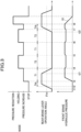
FIG.3] FIG. 3 is a flowchart illustrating a change in each parameter from when brake hold control starts to when the brake hold control ends due to establishment of a release condition. - [
FIG. 4] FIG. 4 is a flowchart illustrating a change in each parameter from when brake hold control starts to when the brake hold control ends due to establishment of a condition of an intention to start from a standstill. - Hereinafter, an embodiment of the invention will be described in detail with reference to the drawings as appropriate.
- As illustrated in
FIG. 1 , a motorcycle MC as an example of a bar handle vehicle includes an engine ENG, a transmission TM, and a brake fluid pressure control device C for a bar handle vehicle. - The engine ENG is a driving source that applies a driving force to a rear wheel WR, and is coupled to the rear wheel WR via the transmission TM. That is, in the motorcycle MC of the embodiment, the rear wheel WR is a driving wheel and a front wheel WF is a driven wheel. The engine ENG is provided with a
throttle sensor 54 that detects an opening degree of a throttle valve of the engine ENG. The opening degree of the throttle valve increases as an operation amount of an accelerator AC increases. The transmission TM is a mechanism that changes output of the driving force of the engine ENG and transmits the driving force to the rear wheel WR. Aspeed detection sensor 52 is provided near an output shaft of the transmission TM. - The
speed detection sensor 52 is a sensor (so-called speedometer sensor) that detects a wheel speed of the rear wheel WR, and detects a wheel speed corresponding to a speed displayed by a speedometer (not shown). Thespeed detection sensor 52 has a different detection mode from awheel speed sensor 51 that detects a wheel speed of the front wheel WF. Here, thewheel speed sensor 51 is a sensor that generates a pulse wave accompanying wheel rotation. - The brake fluid pressure control device C for a bar handle vehicle includes a brake system BF of the front wheel WF, a brake system BR of the rear wheel WR, and a
controller 100. - The brake system BF mainly includes a front brake lever LF as an example of a driven wheel side brake operating member, a master cylinder MF, a
hydraulic unit 10, afront brake 20F as an example of a driven wheel side brake, apipe 30 connecting the master cylinder MF and aninput port 11a of thehydraulic unit 10, and apipe 40 connecting anoutput port 11b of thehydraulic unit 10 and thefront brake 20F. - The front brake lever LF is an operating lever for operating the
front brake 20F, is disposed on the right side of a handlebar of the motorcycle MC, and can be operated by a rider's right hand. - The master cylinder MF is a device that outputs a hydraulic pressure corresponding to an operation amount of the front brake lever LF.
- The
front brake 20F is a brake that brakes the front wheel WF. Thefront brake 20F mainly includes abrake rotor 21, a brake pad (not shown), and awheel cylinder 23 that generates a brake force (braking force) by pushing the brake pad against thebrake rotor 21 by a hydraulic pressure output from the master cylinder MF. - The
hydraulic unit 10 is a unit for increasing, holding, and reducing the hydraulic pressure of thefront brake 20F. Thehydraulic unit 10 is implemented by disposing various solenoid valves and the like on apump body 11 that is a base body having a fluid line (a hydraulic pressure line) through which a brake fluid flows. In a normal state, a continuous fluid line runs from theinput port 11a to theoutput port 11b of thepump body 11, so that the hydraulic pressure output from the master cylinder MF is transmitted to thefront brake 20F. - A pressure regulator 7, which is a normally open proportional solenoid valve capable of adjusting a difference in hydraulic pressure between hydraulic pressure lines at the upstream and downstream sides in accordance with a supplied current, is provided on the hydraulic pressure line connecting the
input port 11a and theoutput port 11b. At the pressure regulator 7, acheck valve 7a is provided in parallel thereto that allows only a flow to anoutput port 11b side. - An
inlet valve 1, which is a normally open solenoid valve, is disposed on the hydraulic pressure line between the pressure regulator 7 and theoutput port 11b. At theinlet valve 1, acheck valve 1a is provided in parallel thereto that allows only a flow to a pressure regulator 7 side. - A reflux
hydraulic pressure line 19B connected to a hydraulic pressure line between the pressure regulator 7 and theinlet valve 1 is provided from a hydraulic pressure line between theoutput port 11b and theinlet valve 1 via anoutlet valve 2 formed of a normally closed solenoid valve. - A
reservoir 3 for temporarily absorbing a surplus brake fluid, a check valve 3a, apump 4, and anorifice 4a are arranged in this order from anoutlet valve 2 side on the refluxhydraulic pressure line 19B. The check valve 3a is disposed so as to allow only a flow to the hydraulic pressure line between the pressure regulator 7 and theinlet valve 1. Thepump 4 is driven by amotor 6, and is provided to generate a pressure toward the hydraulic pressure line between the pressure regulator 7 and theinlet valve 1. Theorifice 4a attenuates pulsation of the pressure of the brake fluid discharged from thepump 4 and pulsation generated by operation of the pressure regulator 7. - An introduction
hydraulic pressure line 19A, which connects theinput port 11a and the pressure regulator 7, and a portion between the check valve 3a and thepump 4 in the refluxhydraulic pressure line 19B are connected by a suctionhydraulic pressure line 19C. Amechanical suction valve 8 is provided in the suctionhydraulic pressure line 19C. - The
suction valve 8 switches between a state of opening the suctionhydraulic pressure line 19C and a state of blocking the suctionhydraulic pressure line 19C. Thesuction valve 8 is normally closed, and is opened based on a difference between a hydraulic pressure of a hydraulic fluid on a master cylinder MF side and a hydraulic pressure of a hydraulic fluid on a suction port side of thepump 4 which is a vacuum pressure in operation of thepump 4. - In the
hydraulic unit 10 configured as described above, in a normal state, each solenoid valve is not energized, and the brake hydraulic pressure introduced from theinput port 11a is output to theoutput port 11b through the pressure regulator 7 and theinlet valve 1, and is applied to thefront brake 20F as it is. When reducing an excessive brake hydraulic pressure of thefront brake 20F, for example, when performing anti-locking braking control, theinlet valve 1 is closed and theoutlet valve 2 is opened to allow the brake fluid to flow to thereservoir 3 through the refluxhydraulic pressure line 19B, so that the brake fluid of thefront brake 20F can be drained. In a case of increasing the hydraulic pressure of thefront brake 20F when the front brake lever LF is not operated by the rider, thesuction valve 8 is opened by driving themotor 6, and the brake fluid can be actively supplied to thefront brake 20F by an increased pressure of thepump 4. Further, when it is desired to adjust the degree of the pressure increase of thefront brake 20F, the adjustment can be performed by adjusting a current flowing through the pressure regulator 7. - The brake system BR mainly includes a rear brake lever LR as an example of a driving wheel side brake operating member, an
angle sensor 53, arear brake 20R as an example of a driving wheel side brake, and a wire W connecting the rear brake lever LR and therear brake 20R. - The rear brake lever LR is an operating lever for operating the
rear brake 20R, is disposed on the left side of the handlebar of the motorcycle MC, and can be operated by the rider's left hand. - The
angle sensor 53 is a sensor for detecting an operation angle of the rear brake lever LR. - The
rear brake 20R is a brake that brakes the rear wheel WR, and is a mechanical brake that operates when a force generated at the time the rear brake lever LR is gripped is transmitted via the wire W. Therear brake 20R is, for example, a drum brake, and includes adrum 25, a brake shoe (not shown), and a return spring (not shown). - The
drum 25 is rotatable integrally with the rear wheel WR. The brake shoe is rotatable between a contact position where the brake shoe comes into contact with an inner peripheral surface of thedrum 25 and a separation position where the brake shoe is separated from the inner peripheral surface of thedrum 25. The return spring biases the brake shoe from the contact position to the separation position. When the rider grips the rear brake lever LR, the wire W is pulled by the rear brake lever LR, whereby the brake shoe rotates from the separation position toward the contact position against a biasing force of the return spring. - The
controller 100 includes, for example, a central processing unit (CPU), a random access memory (RAM), a read only memory (ROM), and an input and output circuit. Thecontroller 100 controls thehydraulic unit 10 by performing various types of calculation processing based on inputs from thewheel speed sensor 51, thespeed detection sensor 52, theangle sensor 53, and thethrottle sensor 54, and programs, data, and the like stored in the ROM. - Specifically, the
controller 100 has a function of executing brake hold control including pressure increase control of increasing the hydraulic pressure of thefront brake 20F and holding control of holding the hydraulic pressure of thefront brake 20F. In the pressure increase control, thecontroller 100 does not supply a current to flow through theinlet valve 1 and theoutlet valve 2, and supplies a current corresponding to a command current value to the pressure regulator 7 to drive themotor 6. When thesuction valve 8 is opened by driving themotor 6 and the pressure increase control is executed, the hydraulic pressure of thefront brake 20F is increased to a predetermined pressure corresponding to the command current value to the pressure regulator 7, and then is maintained at the predetermined pressure. - When switching the pressure increase control to the holding control, the
controller 100 stops themotor 6 while maintaining each solenoid valve in their states presented during the pressure increase control. When thesuction valve 8 is closed due to stop of themotor 6 and the holding control is executed, the hydraulic pressure of thefront brake 20F is held at the predetermined pressure corresponding to the command current value to the pressure regulator 7, following the pressure increase control. When switching the holding control to the pressure increase control, thecontroller 100 drives themotor 6 while maintaining each solenoid valve in their states presented during the holding control. That is, after executing the pressure increase control once, thecontroller 100 switches the holding control and the pressure increase control by switching a driving state of themotor 6. - When it is determined that the motorcycle MC is stopped and a condition for maintaining the vehicle stop is satisfied, the
controller 100 executes (starts) the brake hold control. In the embodiment, thecontroller 100 determines whether the motorcycle MC is stopped, based on speed information acquired from thewheel speed sensor 51 or thespeed detection sensor 52 and throttle opening degree information acquired from thethrottle sensor 54. Here, the speed information may be a wheel speed or may be a vehicle body velocity calculated based on the wheel speed. - When the speed indicated by the speed information is equal to or lower than a first speed and the throttle opening degree indicated by the throttle opening degree information is equal to or less than a first opening degree, the
controller 100 determines that the motorcycle MC is stopped. - The first speed may be a value close to 0, for example, 0. The first opening degree may be a value close to 0, for example, 0. Hereinafter, a condition used for the vehicle stop determination described above is also referred to as a vehicle stop condition.
- In the embodiment, the condition for maintaining the vehicle stop is a condition that an operation on the rear brake lever LR is continued for a predetermined time or longer. The
controller 100 determines, based on a signal from theangle sensor 53, whether the rear brake lever LR is operated. For example, when the operation angle acquired from theangle sensor 53 is equal to or smaller than a predetermined angle θth, thecontroller 100 determines that the rear brake lever LR is not operated, and when the operation angle acquired from theangle sensor 53 is larger than the predetermined angle θth, thecontroller 100 determines that the rear brake lever LR is operated. The predetermined angle θth may be, for example, an angle larger than 0 (seeFIG. 3 ). - When it is determined that a first condition is satisfied after executing the pressure increase control, the
controller 100 switches the pressure increase control to the holding control. In the embodiment, the first condition is that a first time elapses from the start of the pressure increase control. Here, the first time is a time equal to or longer than a time taken for the hydraulic pressure of thefront brake 20F to increase from 0 to the predetermined pressure by the pressure increase control, and is appropriately determined by an experiment, a simulation, or the like. - When it is determined that a second condition is satisfied after executing the holding control, the
controller 100 switches the holding control to the pressure increase control. In the embodiment, the second condition is that a second time elapses from the start of the holding control. Here, the second time is appropriately determined by an experiment, a simulation, or the like to a time in which, even when the hydraulic pressure of thefront brake 20F gradually decreases during the holding control due to the opening degree of the pressure regulator 7 or the like, the hydraulic pressure of thefront brake 20F does not decrease accordingly. The first time and the second time may be different times or may be the same time. - When a release condition for releasing the brake hold control is satisfied, the
controller 100 reduces the hydraulic pressure of thefront brake 20F at a first gradient. In the embodiment, the release condition is that, after the rear brake lever LR is gripped again, the operation is continued for a predetermined time or longer, or that the above-described vehicle stop condition is not satisfied. Here, the determination as to whether the rear brake lever LR is gripped again can be performed by determining whether the rear brake lever LR in a non-operated state is operated, for example, whether the operation angle of the rear brake lever LR becomes equal to or greater than the predetermined angle θth from a state of being 0. Although the predetermined time in the release condition and the predetermined time in the condition for maintaining the vehicle stop are the same time in the embodiment, the predetermined times may be different times. When the hydraulic pressure of thefront brake 20F is reduced at the first gradient, thecontroller 100 sets states of each solenoid valve and the motor to the same states as in the holding control, and gradually decreases the magnitude of the command current value to the pressure regulator 7. - When the rider has an intention to start from a standstill, the
controller 100 reduces the hydraulic pressure of thefront brake 20F at a second gradient larger than the first gradient. Specifically, when the operation amount of the accelerator AC is equal to or greater than a predetermined amount, or when the wheel speed or the vehicle body velocity exceeds a predetermined threshold, thecontroller 100 reduces the hydraulic pressure of thefront brake 20F at a second gradient larger than the first gradient. In the embodiment, the determination as to whether the operation amount of the accelerator AC is equal to or greater than the predetermined amount is performed by determining whether the throttle opening degree information acquired from thethrottle sensor 54 is equal to or greater than a second opening degree larger than the first opening degree described above. The determination as to whether the wheel speed or the vehicle body velocity exceeds the predetermined threshold is performed by determining whether the speed information acquired from thewheel speed sensor 51 or thespeed detection sensor 52 exceeds a second speed higher than the first speed. - When the hydraulic pressure of the
front brake 20F is reduced at the second gradient, thecontroller 100 sets the states of each solenoid valve and the motor to the same states as in the holding control, and sets the command current value for the pressure regulator 7 to zero. Specifically, for example, thecontroller 100 reduces the hydraulic pressure of thefront brake 20F at the second gradient by stopping power supply to each solenoid valve and the motor. - A method of releasing the hydraulic pressure from the
outlet valve 2 by causing a current to flow through theinlet valve 1 and theoutlet valve 2 and causing no current to flow through the other solenoid valves may be adopted as a method of reducing the hydraulic pressure of thefront brake 20F at the second gradient. - Next, the operation of the
controller 100 will be described in detail. Thecontroller 100 repeatedly executes the processing shown inFIG. 2 at all times. - In the processing in
FIG. 2 , thecontroller 100 first determines whether the motorcycle MC is stopped (S1). If it is determined in step S1 that the motorcycle MC is stopped (Yes), thecontroller 100 determines whether the operation on the rear brake lever LR is continued for a predetermined time or longer (S2). In step S1 or step S2, if it is determined to be No, thecontroller 100 ends the processing. - If it is determined in step S2 that the operation is continued for the predetermined time or longer (Yes), the
controller 100 starts the pressure increase control (S3). After step S3, thecontroller 100 determines whether the first time elapses from the start of the pressure increase control (S4). - If it is determined in step S4 that the first time does not elapse (No), the
controller 100 determines whether the release condition is satisfied or whether the rider has an intention to start from a standstill (S7). If it is determined in step S7 that the release condition is not satisfied and there is no intention to start from a standstill (No), thecontroller 100 returns to the processing of step S3 and continues the pressure increase control. If it is determined in step S4 that the first time elapses (Yes), thecontroller 100 starts the holding control (S5). - After step S5, the
controller 100 determines whether the second time elapses from the start of the holding control (S6). If it is determined in step S6 that the second time elapses (Yes), thecontroller 100 returns to step S3 and starts the pressure increase control. If it is determined in step S6 that the second time does not elapse (No), thecontroller 100 determines whether the release condition is satisfied, or whether the rider has an intention to start from a standstill (S8). - If it is determined in step S8 that the release condition is not satisfied and there is no intention to start from a standstill (No), the
controller 100 returns to the processing of step S6 and continues the holding control. In step S7 or step S8, if it is determined to be Yes, thecontroller 100 determines whether the rider has an intention to start from a standstill, that is, whether a condition for ending the brake hold control is a condition of an intention to start from a standstill (S9). - If it is determined in step S9 that the condition for ending the brake hold control is not the condition of an intention to start from a standstill (No), since the condition for ending the brake hold control is the release condition, the
controller 100 gradually reduces the hydraulic pressure of thefront brake 20F at the first gradient (S10), and then ends the processing. If it is determined in step S9 that the condition for ending the brake hold control is the condition of an intention to start from a standstill (Yes), thecontroller 100 reduces the hydraulic pressure of thefront brake 20F at the second gradient without stopping (S11), and ends the processing. - Next, a specific example of the operation of the
controller 100 will be described in detail. - As illustrated in
FIG. 3 , when the rider operates the rear brake lever LR (time-point t1) in a state where the motorcycle MC is stopped and the operation angle of the rear brake lever LR becomes equal to or greater than the predetermined angle θth (time-point t2), thecontroller 100 determines that the rear brake lever LR is operated. - When a time over which the operation angle becomes equal to or greater than the predetermined angle θth becomes a predetermined time Tth or longer (time-point t3), the
controller 100 starts the pressure increase control. Accordingly, the hydraulic pressure of thefront brake 20F increases. - When a first time T1 elapses from the start of the pressure increase control (time-point t4), the
controller 100 switches the pressure increase control to the holding control. Accordingly, the hydraulic pressure of thefront brake 20F is held. - When a second time T2 elapses from the start of the holding control (time-point t5), the
controller 100 starts the pressure increase control again. Thereafter, similarly, the holding control and the pressure increase control are alternately executed in accordance with the passage of time (time-points t6 and t7). - When the rider releases the rear brake lever LR from his/her hand during the brake hold control (time-point t21), the operation angle of the rear brake lever LR decreases and becomes 0 (time-point t4). When the rider grips the rear brake lever LR again (time-point t22), the operation angle of the rear brake lever LR increases.
- When the predetermined time Tth elapses (time-point t8) after the operation angle of the rear brake lever LR becomes equal to or greater than the predetermined angle θth from 0 during the brake hold control, the
controller 100 gradually reduces the hydraulic pressure of thefront brake 20F at a first gradient G1. As illustrated inFIG. 4 , when there is an intention to start from a standstill such as the rider operating the accelerator AC during the brake hold control (time-point t41), thecontroller 100 reduces the hydraulic pressure of thefront brake 20F at a second gradient G2 larger than the first gradient G1 without stopping. - According to the above, the following effects can be obtained in the embodiment.
- Since the brake hold control can be executed without providing a hydraulic unit for the rear wheel WR that is the driving wheel, the cost can be reduced.
- By alternately switching the pressure increase control and the holding control, for example, even when the hydraulic pressure slightly decreases during the holding control, the pressure increase control is executed thereafter, so that the hydraulic pressure of the
front brake 20F can be favorably maintained at the predetermined pressure. - Since the switching between the pressure increase control and the holding control is performed based on the time, a detection means such as a hydraulic pressure sensor is not required, and an inexpensive configuration can be implemented.
- When the release condition of the brake hold control is satisfied, since the hydraulic pressure of the
front brake 20F is gradually reduced at the first gradient G1, it is possible to restrict the rider from having a feeling of discomfort. - When the rider has an intention to start from a standstill, since the hydraulic pressure of the
front brake 20F is reduced at the second gradient G2 larger than the first gradient G1, the pressure reduction is performed quickly, and the motorcycle MC can be caused to start from a standstill smoothly. - By setting the operation on the rear brake lever LR as the condition for maintaining the vehicle stop, it is possible to accurately determine whether the rider has an intention to maintain the vehicle stop.
- Since whether the rear brake lever LR is operated is determined based on a signal from the
angle sensor 53, for example, this configuration can be made less expensive than when the operation on the rear brake lever is determined using another sensor. - Since the
rear brake 20R is a mechanical brake, the brake fluid pressure control device C for a bar handle vehicle can be implemented to have an inexpensive configuration. - The invention is not limited to the above-described embodiment, and can be used in various forms as exemplified below. In the following description, members having substantially the same structures as those of the above-described embodiment are denoted by the same reference signs, and a description thereof is omitted.
- The bar handle vehicle is not limited to the motorcycle MC, and may be any vehicle that is operated with a bar handle, for example, a three-wheeled vehicle or a four-wheeled vehicle.
- Although the driving wheel is the rear wheel WR and the driven wheel is the front wheel WF in the above-described embodiment, for example, the driving wheel may be the front wheel and the driven wheel may be the rear wheel.
- The condition for maintaining the vehicle stop is not limited to the condition described in the above-described embodiment, and may be, for example, a condition that the operation on the driven wheel side brake operating member is continued for a predetermined time or longer.
- The first condition and the second condition are not limited to the conditions described in the above-described embodiment. The first condition may be, for example, that the hydraulic pressure of the driven wheel side brake becomes equal to or greater than a first threshold, and the second condition may be, for example, that the hydraulic pressure of the driven wheel side brake becomes less than a second threshold smaller than the first threshold. In this case, it is sufficient to provide a hydraulic pressure sensor configured to detect the hydraulic pressure of the driven wheel side brake.
- The brake operating member is not limited to a lever, and may be, for example, a foot brake pedal.
- The driving wheel side brake may be a hydraulic brake. Also in this case, the cost can be reduced by not providing a hydraulic unit for the driving wheel side brake.
- The suction valve may be a normally closed solenoid valve.
- The elements described in the above-described embodiment and the modification may be combined as desired.
Claims (8)
- A brake fluid pressure control device for a bar handle vehicle, the device comprising:a driving wheel side brake configured to brake a driving wheel;a driven wheel side brake configured to brake a driven wheel;a hydraulic unit configured to increase, hold, and reduce a hydraulic pressure of the driven wheel side brake; anda controller configured to control the hydraulic unit, whereinwhen it is determined that a bar handle vehicle is stopped and a condition for maintaining a vehicle stop is satisfied, the controller executes brake hold control including pressure increase control of increasing the hydraulic pressure of the driven wheel side brake and holding control of holding the hydraulic pressure of the driven wheel side brake.
- The brake fluid pressure control device for a bar handle vehicle according to claim 1, wherein the controllerswitches the pressure increase control to the holding control when it is determined that a first condition is satisfied after executing the pressure increase control, andswitches the holding control to the pressure increase control when it is determined that a second condition is satisfied after executing the holding control.
- The brake fluid pressure control device for a bar handle vehicle according to claim 2, whereinthe first condition is that a first time elapses from start of the pressure increase control, andthe second condition is that a second time elapses from start of the holding control.
- The brake fluid pressure control device for a bar handle vehicle according to claim 1, wherein
when a release condition for releasing the brake hold control is satisfied, the controller reduces the hydraulic pressure of the driven wheel side brake at a first gradient. - The brake fluid pressure control device for a bar handle vehicle according to claim 4, wherein
when an operation amount of an accelerator is equal to or greater than a predetermined amount, or when a wheel speed or a vehicle body velocity exceeds a predetermined threshold, the controller reduces the hydraulic pressure of the driven wheel side brake at a second gradient larger than the first gradient. - The brake fluid pressure control device for a bar handle vehicle according to claim 1, further comprisinga driven wheel side brake operating member configured to operate the driven wheel side brake; anda driving wheel side brake operating member configured to operate the driving wheel side brake, whereinthe condition for maintaining a vehicle stop is a condition that an operation on the driving wheel side brake operating member is continued for a predetermined time or longer.
- The brake fluid pressure control device for a bar handle vehicle according to claim 6, wherein
the controller determines, based on a signal from an angle sensor configured to detect an operation angle of the driving wheel side brake operating member, whether the driving wheel side brake operating member is operated. - The brake fluid pressure control device for a bar handle vehicle according to any one of claims 1 to 7, wherein
the driving wheel side brake is a mechanical brake.
Applications Claiming Priority (2)
| Application Number | Priority Date | Filing Date | Title |
|---|---|---|---|
| JP2022033189 | 2022-03-04 | ||
| PCT/JP2023/007894 WO2023167295A1 (en) | 2022-03-04 | 2023-03-02 | Brake fluid pressure control device for bar handle vehicle |
Publications (2)
| Publication Number | Publication Date |
|---|---|
| EP4488127A1 true EP4488127A1 (en) | 2025-01-08 |
| EP4488127A4 EP4488127A4 (en) | 2025-06-25 |
Family
ID=87883753
Family Applications (1)
| Application Number | Title | Priority Date | Filing Date |
|---|---|---|---|
| EP23763552.9A Pending EP4488127A4 (en) | 2022-03-04 | 2023-03-02 | Brake fluid pressure control device for bar handle vehicle |
Country Status (3)
| Country | Link |
|---|---|
| EP (1) | EP4488127A4 (en) |
| JP (1) | JP7738160B2 (en) |
| WO (1) | WO2023167295A1 (en) |
Families Citing this family (1)
| Publication number | Priority date | Publication date | Assignee | Title |
|---|---|---|---|---|
| WO2026003915A1 (en) * | 2024-06-24 | 2026-01-02 | 本田技研工業株式会社 | Vehicle control device |
Family Cites Families (10)
| Publication number | Priority date | Publication date | Assignee | Title |
|---|---|---|---|---|
| JP4235158B2 (en) | 2004-10-18 | 2009-03-11 | 日信工業株式会社 | Brake control device for vehicle |
| JP4784328B2 (en) * | 2005-04-14 | 2011-10-05 | 株式会社アドヴィックス | Control device for motorcycle brake device |
| DE102007025272A1 (en) | 2006-06-14 | 2007-12-27 | Continental Teves Ag & Co. Ohg | Detection method for initiation of starting process of motorcycle by rider, involves measuring state variables e.g. throttle flap angle and engine rotational speed of motorcycle |
| JP5653067B2 (en) | 2010-04-28 | 2015-01-14 | ボッシュ株式会社 | Brake slope support brake device for vehicle and control method thereof |
| JP5817386B2 (en) | 2011-09-26 | 2015-11-18 | スズキ株式会社 | Engine restart control device |
| JP2017114243A (en) * | 2015-12-22 | 2017-06-29 | ローベルト ボッシュ ゲゼルシャフト ミット ベシュレンクテル ハフツング | Control device and control method |
| JP6755619B2 (en) | 2016-06-27 | 2020-09-16 | ダイハツ工業株式会社 | Vehicle braking device |
| WO2020026678A1 (en) * | 2018-07-31 | 2020-02-06 | 日信工業株式会社 | Bar handle vehicle brake device |
| JP2021160673A (en) * | 2020-04-02 | 2021-10-11 | ロベルト・ボッシュ・ゲゼルシャフト・ミト・ベシュレンクテル・ハフツングRobert Bosch Gmbh | Brake system for motorcycles and motorcycles |
| JP7459647B2 (en) | 2020-05-13 | 2024-04-02 | 株式会社デンソー | Engine Control Unit |
-
2023
- 2023-03-02 JP JP2024504760A patent/JP7738160B2/en active Active
- 2023-03-02 EP EP23763552.9A patent/EP4488127A4/en active Pending
- 2023-03-02 WO PCT/JP2023/007894 patent/WO2023167295A1/en not_active Ceased
Also Published As
| Publication number | Publication date |
|---|---|
| WO2023167295A1 (en) | 2023-09-07 |
| JPWO2023167295A1 (en) | 2023-09-07 |
| EP4488127A4 (en) | 2025-06-25 |
| JP7738160B2 (en) | 2025-09-11 |
Similar Documents
| Publication | Publication Date | Title |
|---|---|---|
| CN112566827B (en) | Control device and control method | |
| JP7318541B2 (en) | Braking control device | |
| US12415492B2 (en) | Parking brake control device | |
| JP5632442B2 (en) | Brake hydraulic pressure control device for vehicles | |
| US9120470B2 (en) | Vehicle brake hydraulic pressure controller | |
| JP7738160B2 (en) | Brake fluid pressure control device for bar handle vehicles | |
| US8915555B2 (en) | Brake control device for vehicle | |
| JP7550233B2 (en) | Brake fluid pressure control device for vehicle | |
| JP7804789B2 (en) | Vehicle brake control device | |
| JP4815527B2 (en) | Brake hydraulic pressure control device for vehicles | |
| US12296802B2 (en) | Vehicle brake fluid pressure control device | |
| EP4549301A1 (en) | Vehicle brake control device and brake control method | |
| EP4549262A1 (en) | Vehicle brake control device | |
| KR100976216B1 (en) | Car brake system | |
| JP4815528B2 (en) | Brake hydraulic pressure control device for vehicles | |
| JP2023096205A (en) | Control device for vehicle brake system, vehicle, and control method for vehicle brake system | |
| JP4972575B2 (en) | Brake hydraulic pressure control device for vehicles | |
| WO2025197499A1 (en) | Saddle-riding vehicle control device | |
| JP7851415B2 (en) | Vehicle brake control system | |
| JP2000264182A (en) | Braking force control device and vehicle control device provided with this device | |
| JP3567634B2 (en) | Braking pressure control device | |
| JP2014196082A (en) | Vehicle brake fluid pressure controller | |
| JP6091265B2 (en) | Brake hydraulic pressure control device for vehicles | |
| JP4909222B2 (en) | Brake control device for motorcycle and brake control method for motorcycle | |
| JP6232204B2 (en) | Brake hydraulic pressure control device for vehicles |
Legal Events
| Date | Code | Title | Description |
|---|---|---|---|
| STAA | Information on the status of an ep patent application or granted ep patent |
Free format text: STATUS: THE INTERNATIONAL PUBLICATION HAS BEEN MADE |
|
| PUAI | Public reference made under article 153(3) epc to a published international application that has entered the european phase |
Free format text: ORIGINAL CODE: 0009012 |
|
| STAA | Information on the status of an ep patent application or granted ep patent |
Free format text: STATUS: REQUEST FOR EXAMINATION WAS MADE |
|
| 17P | Request for examination filed |
Effective date: 20240925 |
|
| AK | Designated contracting states |
Kind code of ref document: A1 Designated state(s): AL AT BE BG CH CY CZ DE DK EE ES FI FR GB GR HR HU IE IS IT LI LT LU LV MC ME MK MT NL NO PL PT RO RS SE SI SK SM TR |
|
| DAV | Request for validation of the european patent (deleted) | ||
| DAX | Request for extension of the european patent (deleted) | ||
| A4 | Supplementary search report drawn up and despatched |
Effective date: 20250527 |
|
| RIC1 | Information provided on ipc code assigned before grant |
Ipc: B60T 8/171 20060101ALI20250521BHEP Ipc: B60T 7/12 20060101AFI20250521BHEP |
|
| RAP3 | Party data changed (applicant data changed or rights of an application transferred) |
Owner name: ASTEMO, LTD. |
|
| GRAP | Despatch of communication of intention to grant a patent |
Free format text: ORIGINAL CODE: EPIDOSNIGR1 |
|
| STAA | Information on the status of an ep patent application or granted ep patent |
Free format text: STATUS: GRANT OF PATENT IS INTENDED |
|
| RIC1 | Information provided on ipc code assigned before grant |
Ipc: B60T 7/12 20060101AFI20260610BHEP Ipc: B60T 8/171 20060101ALI20260610BHEP |
|
| INTG | Intention to grant announced |
Effective date: 20260622 |