JP4972575B2 - Brake hydraulic pressure control device for vehicles - Google Patents
Brake hydraulic pressure control device for vehicles Download PDFInfo
- Publication number
- JP4972575B2 JP4972575B2 JP2008028378A JP2008028378A JP4972575B2 JP 4972575 B2 JP4972575 B2 JP 4972575B2 JP 2008028378 A JP2008028378 A JP 2008028378A JP 2008028378 A JP2008028378 A JP 2008028378A JP 4972575 B2 JP4972575 B2 JP 4972575B2
- Authority
- JP
- Japan
- Prior art keywords
- pressure
- brake
- control
- valve
- wheel
- Prior art date
- Legal status (The legal status is an assumption and is not a legal conclusion. Google has not performed a legal analysis and makes no representation as to the accuracy of the status listed.)
- Active
Links
- 239000012530 fluid Substances 0.000 claims description 77
- 238000011144 upstream manufacturing Methods 0.000 claims description 58
- 230000001965 increasing effect Effects 0.000 claims description 28
- 230000009977 dual effect Effects 0.000 claims 1
- 230000001105 regulatory effect Effects 0.000 description 26
- 230000009467 reduction Effects 0.000 description 20
- 230000033228 biological regulation Effects 0.000 description 18
- 230000000875 corresponding effect Effects 0.000 description 12
- 238000000034 method Methods 0.000 description 10
- 238000010586 diagram Methods 0.000 description 6
- 230000008569 process Effects 0.000 description 6
- 230000001133 acceleration Effects 0.000 description 5
- 230000001276 controlling effect Effects 0.000 description 5
- 238000004364 calculation method Methods 0.000 description 4
- 230000003247 decreasing effect Effects 0.000 description 4
- 230000007423 decrease Effects 0.000 description 3
- 230000008859 change Effects 0.000 description 2
- 230000006837 decompression Effects 0.000 description 2
- 238000001514 detection method Methods 0.000 description 2
- 238000007599 discharging Methods 0.000 description 2
- 230000010349 pulsation Effects 0.000 description 2
- 230000002079 cooperative effect Effects 0.000 description 1
- 230000000694 effects Effects 0.000 description 1
- 238000005516 engineering process Methods 0.000 description 1
- 230000006872 improvement Effects 0.000 description 1
- 238000005086 pumping Methods 0.000 description 1
- 230000000717 retained effect Effects 0.000 description 1
Images


Landscapes
- Regulating Braking Force (AREA)
Description
本発明は、フェード判定を実行可能な車両用ブレーキ液圧制御装置に関する。 The present invention relates to a vehicle brake hydraulic pressure control device capable of performing fade determination.
従来、通常よりも大きな制動力を発生させるブレーキアシストの技術として、運転者に応じてブレーキアシストのアシスト量を変更して運転者に適したブレーキアシストの制御を行う技術が知られている(特許文献1参照)。さらに、この技術では、ブレーキアシスト制御によってブレーキ液圧を車輪ブレーキのロック液圧以上まで上げて車輪をロック傾向にさせることで、アンチロックブレーキ制御(以下、ABS制御という。)を作動させて、車輪ブレーキが最も大きな制動力を発揮できるように制御している。一方、車輪ブレーキを頻繁に作動させると、ブレーキパッドの表面の摩擦係数が熱によって低下するといったフェード現象が発生するということは一般に知られている。 Conventionally, as a brake assist technique for generating a braking force larger than usual, a technique is known in which a brake assist control suitable for the driver is performed by changing the assist amount of the brake assist according to the driver (patent) Reference 1). Furthermore, in this technology, the brake fluid pressure is increased to a value higher than the lock fluid pressure of the wheel brake by the brake assist control to cause the wheel to be locked, thereby operating anti-lock brake control (hereinafter referred to as ABS control). The wheel brake is controlled so that it can exert the greatest braking force. On the other hand, it is generally known that when the wheel brake is operated frequently, a fade phenomenon occurs in which the friction coefficient of the surface of the brake pad is reduced by heat.
しかしながら、ブレーキアシストの機能はブレーキパッドが正常な状態であることを前提としているため、前述したフェード現象が発生した場合には、通常のブレーキアシスト制御時と比べ、車輪がロック傾向になり難くなって、ABS制御に入り難くなってしまう場合があった。また、ABS制御中にフェード現象が発生した場合には、ブレーキアシスト制御中であるにも関わらず、車輪がロック傾向になり難くなって、ABS制御が終了し易くなってしまう場合があった。したがって、ブレーキ制御の更なる向上を図るためには、ABS制御中においてもフェード判定を行うことが望まれている。 However, since the brake assist function is based on the assumption that the brake pads are in a normal state, if the above-mentioned fade phenomenon occurs, the wheels are less likely to lock than during normal brake assist control. As a result, it may be difficult to enter the ABS control. Further, when a fade phenomenon occurs during the ABS control, the wheel is less likely to be locked despite the brake assist control being performed, and the ABS control may end easily. Therefore, in order to further improve the brake control, it is desired to perform the fade determination even during the ABS control.
そこで、本発明は、ABS制御中のフェード発生時におけるブレーキ制御の更なる向上に寄与する車両用ブレーキ液圧制御装置を提供することを目的とする。 Therefore, an object of the present invention is to provide a vehicle brake hydraulic pressure control device that contributes to further improvement of brake control when a fade occurs during ABS control.
前記課題を解決するため、本発明に係る車両用ブレーキ液圧制御装置は、運転者によるブレーキ操作子の操作状態に基づいてブレーキアシストが必要か否かを判定し、ブレーキアシストが必要だと判定した場合に、車輪ブレーキ内の液圧をポンプによって増圧させるブレーキアシスト制御手段と、車輪ブレーキの上下流に設けられる入口弁および出口弁を制御することで、前記車輪ブレーキ内の液圧を減圧、保持または増圧させるブレーキ液圧制御手段と、を備えた車両用ブレーキ液圧制御装置であって、前記入口弁の上流側のブレーキ液圧が所定値以上であるか否かを判定する第1判定手段と、前記入口弁の上下流の差圧が所定値以下であるか否かを判定する第2判定手段と、前記第1判定手段で前記上流側のブレーキ液圧が所定値以上であると判定され、かつ、前記第2判定手段で前記差圧が所定値以下であると判定されたことを条件として、前記ブレーキアシスト制御手段による増圧量を増加させる増圧量変更手段と、を備え、前記入口弁は、駆動電流値に応じて上下流の差圧を調整可能な比例電磁弁であり、前記第2判定手段による判定は、前記入口弁の駆動電流値に基づいて行われることを特徴とする。 In order to solve the above-described problem, the vehicle brake hydraulic pressure control device according to the present invention determines whether or not the brake assist is necessary based on the operation state of the brake operator by the driver, and determines that the brake assist is necessary. In this case, the hydraulic pressure in the wheel brake is reduced by controlling the brake assist control means for increasing the hydraulic pressure in the wheel brake by the pump and the inlet and outlet valves provided on the upstream and downstream of the wheel brake. A brake fluid pressure control device for holding or increasing the pressure of the vehicle, wherein the brake fluid pressure control device for determining whether or not the brake fluid pressure upstream of the inlet valve is greater than or equal to a predetermined value is determined. 1 determination means, second determination means for determining whether or not the differential pressure upstream and downstream of the inlet valve is equal to or less than a predetermined value, and the upstream brake fluid pressure at the first determination means is greater than or equal to a predetermined value. And a pressure increase amount changing means for increasing the pressure increase amount by the brake assist control means, on the condition that the second determination means determines that the differential pressure is not more than a predetermined value; And the inlet valve is a proportional electromagnetic valve capable of adjusting the upstream / downstream differential pressure according to the drive current value, and the determination by the second determination means is performed based on the drive current value of the inlet valve It is characterized by that.
本発明によれば、入口弁の上流側のブレーキ液圧が所定値以上であり、かつ、入口弁の上下流の差圧が所定値以下である場合には、ブレーキアシスト制御手段による増圧量が増加される。ここで、前述の条件を満たす際には、ブレーキ液圧制御手段による減圧制御が行われておらず、入口弁の上流側のブレーキ液圧が十分高い値であり、その高いブレーキ液圧が入口弁の下流側の車輪ブレーキに十分伝達されている状態となっている。 According to the present invention, when the brake fluid pressure on the upstream side of the inlet valve is equal to or higher than the predetermined value and the differential pressure on the upstream and downstream of the inlet valve is equal to or lower than the predetermined value, the amount of pressure increase by the brake assist control means Is increased. Here, when the above conditions are satisfied, the pressure reduction control by the brake hydraulic pressure control means is not performed, the brake hydraulic pressure upstream of the inlet valve is a sufficiently high value, and the high brake hydraulic pressure is It is in a state where it is sufficiently transmitted to the wheel brake on the downstream side of the valve.
そのため、このような車輪ブレーキ内のブレーキ液圧が十分高い状態であるにも関わらず、減圧制御が行われていない場合には、例えばフェード現象などが原因となって適切な制動力が得られていないと判断できる。そして、このように判断した場合、本発明ではブレーキアシスト制御手段による増圧量が増加されるので、車輪ブレーキ内のブレーキ液圧を、車輪がロック傾向になるような高い液圧値まで増加することができ、ブレーキ制御の更なる向上を図ることができる。 Therefore, in the case where the brake fluid pressure in the wheel brake is sufficiently high but the pressure reduction control is not performed, an appropriate braking force can be obtained due to, for example, a fade phenomenon. It can be judged that it is not. And when judged in this way, in the present invention, since the amount of pressure increase by the brake assist control means is increased, the brake fluid pressure in the wheel brake is increased to a high fluid pressure value at which the wheel tends to lock. Therefore, the brake control can be further improved.
そして、入口弁の上下流のそれぞれに圧力センサを設けることなく、差圧が所定値以下であるかの判定を行うことができるので、コストの低減を図ることができる。 Since it is possible to determine whether the differential pressure is equal to or less than a predetermined value without providing pressure sensors on the upstream and downstream sides of the inlet valve, the cost can be reduced.
また、本発明は、運転者によるブレーキ操作子の操作状態に基づいてブレーキアシストが必要か否かを判定し、ブレーキアシストが必要だと判定した場合に、車輪ブレーキ内の液圧をポンプによって増圧させるブレーキアシスト制御手段と、車輪ブレーキの上下流に設けられる入口弁および出口弁を制御することで、前記車輪ブレーキ内の液圧を減圧、保持または増圧させるブレーキ液圧制御手段と、を備えた車両用ブレーキ液圧制御装置であって、前記入口弁の上流側のブレーキ液圧が所定値以上であるか否かを判定する第1判定手段と、前記入口弁の上下流の差圧が所定値以下であるか否かを判定する第2判定手段と、前記第1判定手段で前記上流側のブレーキ液圧が所定値以上であると判定され、かつ、前記第2判定手段で前記差圧が所定値以下であると判定されたことを条件として、前記ブレーキアシスト制御手段による増圧量を増加させる増圧量変更手段と、を備え、前記上流側のブレーキ液圧が、前記ブレーキ操作子の操作状態に応じた液圧を発生するマスタシリンダの液圧と、前記マスタシリンダと前記入口弁との間の、前記ポンプから液圧が供給される部分よりもマスタシリンダ側の液圧路に配置される比例電磁弁としてのレギュレータの駆動電流値とに基づいて推定されることを特徴とする。
Further, the present invention determines whether or not brake assist is necessary based on the operating state of the brake operator by the driver, and if it is determined that brake assist is necessary, the hydraulic pressure in the wheel brake is increased by a pump. Brake assist control means for pressurizing, and brake hydraulic pressure control means for reducing, maintaining or increasing the hydraulic pressure in the wheel brake by controlling an inlet valve and an outlet valve provided upstream and downstream of the wheel brake, A vehicle brake fluid pressure control apparatus, comprising: a first determination unit that determines whether or not a brake fluid pressure upstream of the inlet valve is equal to or greater than a predetermined value; and a differential pressure upstream and downstream of the inlet valve Second determining means for determining whether or not is less than a predetermined value, the first determining means determines that the upstream brake fluid pressure is equal to or higher than a predetermined value, and the second determining means Differential pressure On condition that it is determined that the value or less, and a pressure increase amount changing means for increasing the pressure increase amount by the brake assist control means, the brake fluid pressure of the upstream side, the operation of the brake operation element The hydraulic pressure of the master cylinder that generates the hydraulic pressure according to the state and the hydraulic pressure path between the master cylinder and the inlet valve on the master cylinder side relative to the portion where the hydraulic pressure is supplied from the pump. It is estimated based on the drive current value of the regulator as a proportional solenoid valve .
これによれば、入口弁の上流側の圧力を、一般に設けられるマスタシリンダ圧を検出するための圧力センサで検出されるマスタシリンダ圧と、レギュレータの上下流の差圧に対応するレギュレータの駆動電流値とで推定する。そのため、既存のマスタシリンダ圧用の圧力センサとは別の圧力センサを入口弁の上流側に設けなくても、入口弁の上流側の圧力を推定できるので、コストの低減を図ることができる。 According to this, the upstream side pressure of the inlet valve, the master cylinder pressure detected by the pressure sensor for detecting the master cylinder pressure generally provided, and the regulator drive current corresponding to the differential pressure upstream and downstream of the regulator Estimate by value. Therefore, the pressure on the upstream side of the inlet valve can be estimated without providing a pressure sensor different from the existing pressure sensor for master cylinder pressure on the upstream side of the inlet valve, so that the cost can be reduced.
本発明によれば、入口弁の上流側のブレーキ液圧が所定値以上で、かつ、前記入口弁の上下流の差圧が所定値以下である場合に、フェード現象が発生したと判定してブレーキ液圧の増圧を行うことが可能となるため、ABS制御中のフェード発生時におけるブレーキ制御の更なる向上を図ることができる。 According to the present invention, it is determined that a fade phenomenon has occurred when the brake fluid pressure upstream of the inlet valve is equal to or greater than a predetermined value and the upstream / downstream differential pressure of the inlet valve is equal to or smaller than a predetermined value. Since it becomes possible to increase the brake fluid pressure, it is possible to further improve the brake control when a fade occurs during the ABS control.
次に、本発明の実施形態について、適宜図面を参照しながら詳細に説明する。
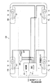
参照する図において、図1は、本発明の実施形態に係る車両用ブレーキ液圧制御装置を備えた車両の構成図であり、図2は、車両用ブレーキ液圧制御装置のブレーキ液圧回路図である。
Next, embodiments of the present invention will be described in detail with reference to the drawings as appropriate.
FIG. 1 is a configuration diagram of a vehicle including a vehicle brake hydraulic pressure control device according to an embodiment of the present invention. FIG. 2 is a brake hydraulic circuit diagram of the vehicle brake hydraulic pressure control device. It is.
図1に示すように、車両用ブレーキ液圧制御装置100は、車両CRの各車輪Wに付与する制動力(ブレーキ液圧)を適宜制御するためのものであり、油路(液圧路)や各種部品が設けられた液圧ユニット10と、液圧ユニット10内の各種部品を適宜制御するための制御部20とを主に備えている。また、この車両用ブレーキ液圧制御装置100の制御部20には、車輪Wの車輪速度を検出する車輪速センサ91が接続されている。また、後述するように、液圧ユニット10にはマスタシリンダMCの圧力を測定する圧力センサ8が設けられている。車輪速センサ91および圧力センサ8の検出結果は、制御部20に出力される。
As shown in FIG. 1, the vehicle brake hydraulic
制御部20は、例えば、CPU、RAM、ROMおよび入出力回路を備えており、車輪速センサ91および圧力センサ8からの入力と、ROMに記憶されたプログラムやデータに基づいて各演算処理を行うことによって、制御を実行する。また、ホイールシリンダHは、マスタシリンダMCおよび車両用ブレーキ液圧制御装置100により発生されたブレーキ液圧を各車輪Wに設けられた車輪ブレーキFR,FL,RR,RLの作動力に変換する液圧装置であり、それぞれ配管を介して車両用ブレーキ液圧制御装置100の液圧ユニット10に接続されている。
The
図2に示すように、車両用ブレーキ液圧制御装置100の液圧ユニット10は、運転者がブレーキペダルBPに加える踏力に応じたブレーキ液圧を発生する液圧源であるマスタシリンダMCと、車輪ブレーキFR,FL,RR,RLとの間に配置されている。液圧ユニット10は、ブレーキ液が流通する油路(液圧路)を有する基体であるポンプボディ10a、油路上に複数配置された入口弁1、出口弁2などから構成されている。マスタシリンダMCの二つの出力ポートM1,M2は、ポンプボディ10aの入口ポート121に接続され、ポンプボディ10aの出口ポート122が、各車輪ブレーキFR,FL,RR,RLに接続されている。そして、通常時はポンプボディ10a内の入口ポート121から出口ポート122までが連通した油路となっていることで、ブレーキペダルBPの踏力が各車輪ブレーキFL,RR,RL,FRに伝達されるようになっている。
As shown in FIG. 2, the
ここで、出力ポートM1から始まる油路は、前輪左側の車輪ブレーキFLと後輪右側の車輪ブレーキRRに通じており、出力ポートM2から始まる油路は、前輪右側の車輪ブレーキFRと後輪左側の車輪ブレーキRLに通じている。なお、以下では、出力ポートM1から始まる油路を「第一系統」と称し、出力ポートM2から始まる油路を「第二系統」と称する。 Here, the oil path starting from the output port M1 leads to the wheel brake FL on the left side of the front wheel and the wheel brake RR on the right side of the rear wheel, and the oil path starting from the output port M2 is set to the wheel brake FR on the right side of the front wheel and the left side of the rear wheel. To the wheel brake RL. Hereinafter, the oil passage starting from the output port M1 is referred to as “first system”, and the oil passage starting from the output port M2 is referred to as “second system”.
液圧ユニット10には、その第一系統に各車輪ブレーキFL,RRに対応して二つの制御弁手段Vが設けられており、同様に、その第二系統に各車輪ブレーキRL,FRに対応して二つの制御弁手段Vが設けられている。また、この液圧ユニット10には、第一系統および第二系統のそれぞれに、リザーバ3、ポンプ4、ダンパ5、オリフィス5a、調圧弁(レギュレータ)R、吸入弁7が設けられている。また、液圧ユニット10には、第一系統のポンプ4と第二系統のポンプ4とを駆動するための共通のモータ9が設けられている。このモータ9は、回転数制御可能なモータであり、本実施形態では、デューティ制御により回転数制御が行われる。また、本実施形態では、第二系統にのみ圧力センサ8が設けられている。
The
なお、以下では、マスタシリンダMCの出力ポートM1,M2から各調圧弁Rに至る油路を「出力液圧路A1」と称し、第一系統の調圧弁Rから車輪ブレーキFL,RRに至る油路および第二系統の調圧弁Rから車輪ブレーキRL,FRに至る油路をそれぞれ「車輪液圧路B」と称する。また、出力液圧路A1からポンプ4に至る油路を「吸入液圧路C」と称し、ポンプ4から車輪液圧路Bに至る油路を「吐出液圧路D」と称し、さらに、車輪液圧路Bから吸入液圧路Cに至る油路を「開放路E」と称する。 In the following, the oil passages from the output ports M1 and M2 of the master cylinder MC to the respective pressure regulating valves R are referred to as “output hydraulic pressure passages A1”, and the oil from the first system pressure regulating valve R to the wheel brakes FL and RR. The oil passages from the road and the second system pressure regulating valve R to the wheel brakes RL and FR are respectively referred to as “wheel hydraulic pressure passage B”. In addition, an oil path from the output hydraulic pressure path A1 to the pump 4 is referred to as “suction hydraulic pressure path C”, an oil path from the pump 4 to the wheel hydraulic pressure path B is referred to as “discharge hydraulic pressure path D”, and The oil passage from the wheel fluid pressure passage B to the suction fluid pressure passage C is referred to as “open passage E”.
制御弁手段Vは、マスタシリンダMCまたはポンプ4から車輪ブレーキFL,RR,RL,FR(詳細には、ホイールシリンダH)への液圧の行き来を制御する弁であり、ホイールシリンダHの圧力を増加、保持または低下させることができる。そのため、制御弁手段Vは、入口弁1、出口弁2、チェック弁1aを備えて構成されている。
The control valve means V is a valve that controls the flow of hydraulic pressure from the master cylinder MC or the pump 4 to the wheel brakes FL, RR, RL, FR (specifically, the wheel cylinder H). Can be increased, retained or decreased. Therefore, the control valve means V includes an inlet valve 1, an
入口弁1は、各車輪ブレーキFL,RR,RL,FRとマスタシリンダMCとの間、すなわち車輪液圧路Bに設けられた常開型のリニアソレノイド弁(比例電磁弁)である。そのため、入口弁1に流す駆動電流値に応じて、入口弁1の上下流の差圧が調整可能となっている。すなわち、入口弁1の上流側が下流側に比べて比較的高い液圧になっている場合において、入口弁1に駆動電流を供給すると、入口弁1の上流側の液圧と下流側の液圧との差圧が、駆動電流に応じた差圧になるまで入口弁1が開いて、入口弁1の下流側が増圧される。 The inlet valve 1 is a normally open linear solenoid valve (proportional solenoid valve) provided between each wheel brake FL, RR, RL, FR and the master cylinder MC, that is, in the wheel hydraulic pressure path B. Therefore, the upstream / downstream differential pressure of the inlet valve 1 can be adjusted in accordance with the drive current value flowing through the inlet valve 1. That is, when the upstream side of the inlet valve 1 has a relatively high hydraulic pressure as compared with the downstream side, when the drive current is supplied to the inlet valve 1, the upstream side hydraulic pressure and the downstream side hydraulic pressure are supplied. The inlet valve 1 is opened until the pressure difference between the two becomes a pressure difference corresponding to the drive current, and the downstream side of the inlet valve 1 is increased.
詳細は図示しないが、入口弁1の弁体は、付与される駆動電流に応じた電磁力によって車輪ブレーキFL,RR,RL,FRとは反対側(入口弁1の上流側)へ付勢されている。そのため、入口弁1の上流側の圧力が入口弁1の下流側の圧力より所定値(この所定値は、付与される電流による)以上高くなった場合には、上流側から下流側へ向けてブレーキ液が流れて、車輪ブレーキFL,RR,RL,FR内が増圧される。 Although not shown in detail, the valve body of the inlet valve 1 is urged to the side opposite to the wheel brakes FL, RR, RL, FR (upstream side of the inlet valve 1) by an electromagnetic force corresponding to the applied drive current. ing. Therefore, when the pressure on the upstream side of the inlet valve 1 is higher than the pressure on the downstream side of the inlet valve 1 by a predetermined value (this predetermined value depends on the applied current), the pressure increases from the upstream side toward the downstream side. The brake fluid flows, and the pressure in the wheel brakes FL, RR, RL, FR is increased.
出口弁2は、各車輪ブレーキFL,RR,RL,FRと各リザーバ3との間、すなわち車輪液圧路Bと開放路Eとの間に介設された常閉型の電磁弁である。出口弁2は、通常時に閉塞されているが、車輪Wがロックしそうになったときに制御部20により開放されることで、各車輪ブレーキFL,FR,RL,RRに作用するブレーキ液圧を各リザーバ3に逃がす。
The
チェック弁1aは、各入口弁1に並列に接続されている。このチェック弁1aは、各車輪ブレーキFL,FR,RL,RR側からマスタシリンダMC側へのブレーキ液の流入のみを許容する弁であり、ブレーキペダルBPからの入力が解除された場合に、入口弁1を閉じた状態にしたときにおいても、各車輪ブレーキFL,FR,RL,RR側からマスタシリンダMC側へのブレーキ液の流入を許容する。
The
リザーバ3は、開放路Eに設けられており、各出口弁2が開放されることによって逃がされるブレーキ液圧を貯留する機能を有している。また、リザーバ3とポンプ4との間には、リザーバ3側からポンプ4側へのブレーキ液の流れのみを許容するチェック弁3aが介設されている。
The
ポンプ4は、出力液圧路A1に通じる吸入液圧路Cと車輪液圧路Bに通じる吐出液圧路Dとの間に介設されており、リザーバ3で貯留されているブレーキ液を吸入して吐出液圧路Dに吐出する機能を有している。これにより、リザーバ3により吸収されたブレーキ液をマスタシリンダMCに戻すことができるとともに、後述するようにブレーキペダルBPの操作の有無に関わらずブレーキ液圧を発生して、車輪ブレーキFL,RR,RL,FRに制動力を発生することができる。
The pump 4 is interposed between the suction hydraulic pressure path C leading to the output hydraulic pressure path A1 and the discharge hydraulic pressure path D leading to the wheel hydraulic pressure path B, and sucks the brake fluid stored in the
なお、ポンプ4によるブレーキ液の吐出量は、モータ9の回転数(デューティ比)に依存している。すなわち、モータ9の回転数(デューティ比)が大きくなると、ポンプ4によるブレーキ液の吐出量も大きくなる。 The amount of brake fluid discharged by the pump 4 depends on the rotation speed (duty ratio) of the motor 9. That is, as the rotation speed (duty ratio) of the motor 9 increases, the amount of brake fluid discharged by the pump 4 also increases.
ダンパ5およびオリフィス5aは、その協働作用によってポンプ4から吐出されたブレーキ液の圧力の脈動および後記する調圧弁Rが作動することにより発生する脈動を減衰させている。
The damper 5 and the
調圧弁Rは、通常時に出力液圧路A1から車輪液圧路Bへのブレーキ液の流れを許容するとともに、ポンプ4が発生したブレーキ液圧によりホイールシリンダH側の圧力を増加するときには、この流れを遮断しつつ、吐出液圧路D、車輪液圧路Bおよび制御弁手段V(ホイールシリンダH)側の圧力を設定値以下に調節する機能を有し、切換弁6およびチェック弁6aを備えて構成されている。
The pressure regulating valve R permits the flow of brake fluid from the output hydraulic pressure path A1 to the wheel hydraulic pressure path B during normal times, and increases the pressure on the wheel cylinder H side by the brake hydraulic pressure generated by the pump 4. It has a function of adjusting the pressure on the discharge hydraulic pressure passage D, wheel hydraulic pressure passage B and control valve means V (wheel cylinder H) side to a set value or less while shutting off the flow. The switching valve 6 and the
切換弁6は、マスタシリンダMCに通じる出力液圧路A1と各車輪ブレーキFL,FR,RL,RRに通じる車輪液圧路Bとの間に介設された常開型のリニアソレノイド弁である。そのため、切換弁6に流す駆動電流の値に応じて、切換弁6の上下流の差圧が調整されることによって、吐出液圧路Dおよび車輪液圧路Bの圧力を設定値以下に調節可能となっている。 The switching valve 6 is a normally open type linear solenoid valve interposed between the output hydraulic pressure path A1 leading to the master cylinder MC and the wheel hydraulic pressure path B leading to each wheel brake FL, FR, RL, RR. . Therefore, the pressure in the discharge hydraulic pressure path D and the wheel hydraulic pressure path B is adjusted to be equal to or lower than the set value by adjusting the differential pressure upstream and downstream of the switching valve 6 according to the value of the drive current flowing through the switching valve 6. It is possible.
詳細は図示しないが、切換弁6の弁体は、付与される駆動電流に応じた電磁力によって車輪液圧路BおよびホイールシリンダH側へ付勢されており、車輪液圧路Bの圧力が出力液圧路A1の圧力より所定値(この所定値は、付与される電流による)以上高くなった場合には、車輪液圧路Bから出力液圧路A1へ向けてブレーキ液が逃げることで、車輪液圧路B側の圧力が所定圧に調整される。
なお、切換弁6に付与する駆動電流は、デューティ制御により制御される。
Although not shown in detail, the valve body of the switching valve 6 is urged toward the wheel hydraulic pressure path B and the wheel cylinder H by the electromagnetic force corresponding to the applied drive current, and the pressure in the wheel hydraulic pressure path B is increased. When the pressure is higher than the pressure in the output hydraulic pressure path A1 by a predetermined value (this predetermined value depends on the applied current), the brake fluid escapes from the wheel hydraulic pressure path B toward the output hydraulic pressure path A1. The pressure on the wheel hydraulic pressure path B side is adjusted to a predetermined pressure.
The drive current applied to the switching valve 6 is controlled by duty control.
チェック弁6aは、各切換弁6に並列に接続されている。このチェック弁6aは、出力液圧路A1から車輪液圧路Bへのブレーキ液の流れを許容する一方向弁である。
The
吸入弁7は、吸入液圧路Cに設けられた常閉型の電磁弁であり、吸入液圧路Cを開放する状態および遮断する状態を切り換えるものである。吸入弁7は、切換弁6が閉じるとき、例えば、BA制御時において各車輪ブレーキFL,FR,RL,RRにブレーキ液圧を作用させるときに制御部20の制御により開放(開弁)される。
The
圧力センサ8は、出力液圧路A1のブレーキ液圧を検出するものであり、その検出結果は制御部20に入力される。
The
次に、制御部20の詳細について説明する。参照する図面において、図3は、制御部の構成を示すブロック図である。
Next, details of the
図3に示すように、制御部20は、車輪速センサ91および圧力センサ8から入力された信号に基づき、液圧ユニット10内の制御弁手段V、調圧弁R(切換弁6)および吸入弁7の開閉動作ならびにモータ9の動作を制御して、各車輪ブレーキFL,RR,RL,FRの動作を制御するものである。制御部20は、機能手段としてスリップ率演算部21、ABS制御手段(ブレーキ液圧制御手段)22、BA制御手段(ブレーキアシスト制御手段)23、弁駆動部25、モータ駆動部26、記憶部29、フェード判定手段30および増圧量変更手段31を備えている。
As shown in FIG. 3, the
スリップ率演算部21は、車輪速センサ91が検出した各車輪Wの回転角速度に基づき、公知の方法によりスリップ率を演算する部分である。スリップ率の計算方法について一例を挙げれば、スリップ率演算部21は、車輪Wの回転角速度を車輪外周の速度(車輪速度V1)に換算し、さらに、車体速度V0を推定する。車体速度V0の推定方法は、例えば各車輪のうち速度が最大の車輪速度V1など、路面に追従していると思われる車輪速度V1を車体速度V0とするなどして車体速度V0を推定する方法が挙げられる。車体速度V0と車輪速度V1が得られれば、スリップ率は、(V0−V1)×100/V0により求めることができる。
The slip
ABS制御手段22は、スリップ率演算部21が演算したスリップ率と、車輪速度に基づいて算出する車輪加速度とに基づき、ABS制御を実行する手段である。ABS制御手段22は、スリップ率が所定値以上になり、かつ、車輪加速度が0以下であるときに、車輪Wのロックを防止すべく、制御弁手段駆動部25aを制御して、ホイールシリンダHを減圧する。すなわち、ABS制御手段22は、減圧制御を開始する場合には、制御弁手段駆動部25aに減圧の指示を出力する。制御弁手段駆動部25aは、減圧の指示を受けると、後述するように入口弁1を閉じて、出口弁2を開くことにより、ホイールシリンダH内のブレーキ液をリザーバ3に排出して、ホイールシリンダHを減圧する。
The ABS control means 22 is means for executing ABS control based on the slip ratio calculated by the slip
次いで、車輪加速度が0よりも大きくなったときには、ABS制御手段22は、入口弁1と出口弁2の双方を閉じてホイールシリンダH内のブレーキ液圧を保持する。すなわち、ABS制御手段22は、保持制御を開始する場合には、制御弁手段駆動部25aに保持の指示を出力する。制御弁手段駆動部25aは、保持の指示を受けると、後述するように入口弁1および出口弁2の双方を閉じることにより、ホイールシリンダ圧を保持する。
Next, when the wheel acceleration becomes greater than 0, the ABS control means 22 closes both the inlet valve 1 and the
次いで、スリップ率が所定値未満となり、かつ、車輪加速度が0以下となったときには、ABS制御手段22は、入口弁1を開き、出口弁2を閉じることでホイールシリンダHを増圧する。すなわち、ABS制御手段22は、増圧制御を開始する場合には、制御弁手段駆動部25aに増圧の指示を出力する。制御弁手段駆動部25aは、増圧の指示を受けると、後述するように出口弁2を閉じ、入口弁1を徐々に開くことにより、ホイールシリンダH内のブレーキ液圧を徐々に増加させる。
Next, when the slip ratio becomes less than a predetermined value and the wheel acceleration becomes 0 or less, the ABS control means 22 opens the inlet valve 1 and closes the
BA制御手段23は、緊急ブレーキ操作がなされたと判定した場合にポンプ4(モータ9)、吸入弁7および調圧弁Rを制御して、調圧弁RよりもホイールシリンダH側(制御弁手段V側)、つまり、吐出液圧路Dのブレーキ液を加圧するブレーキアシスト制御(BA制御)を実行する手段である。BA制御手段23は、運転者によるブレーキペダルBPの操作状態に基づいて、公知の方法により運転者の緊急ブレーキ操作がなされたか否か(ブレーキアシストが必要か否か)を判定する。例えば、圧力センサ8の履歴を記憶部29に記憶しておき、所定の勾配以上の早さでマスタシリンダ圧が増加した場合に、緊急ブレーキ操作がなされたと判断することができる。また、図示はしないが、ブレーキペダルBPの操作速度などを検出して緊急ブレーキ操作を判断してもよい。
The BA control means 23 controls the pump 4 (motor 9), the
緊急ブレーキ操作があったと判断した場合で、マスタシリンダ圧が十分でない場合、例えば、運転者のブレーキペダルBPの踏力が不十分な場合には、制動力を補助するため、BA制御手段23は、ホイールシリンダHを加圧する。そのため、BA制御手段23は、モータ駆動部26にモータ駆動の信号を出力し、吸入弁駆動部25cに吸入弁7を開く信号を出力し、調圧弁駆動部25bに目標調圧値を指示する。この調圧目標値は、調圧弁Rの制御弁手段V(ホイールシリンダH)側とマスタシリンダMC側の差圧であり、調圧弁Rに流す駆動電流値(デューティ比)として出力される。
When it is determined that an emergency brake operation has been performed and the master cylinder pressure is not sufficient, for example, when the driver's pedal force of the brake pedal BP is insufficient, the BA control means 23 is used to assist the braking force. Pressurize the wheel cylinder H. Therefore, the
BA制御中においては、最も大きな制動力を発揮するため、望ましくは各車輪Wがロック傾向になる寸前の状態に各ホイールシリンダHの液圧を制御するのがよい。BA制御中においてABS制御が常にONになるようにすれば、この理想的な状態に近い状態を得ることができる。一方で,ABS制御における減圧があまり頻繁に発生すると、ホイールシリンダHからリザーバ3にブレーキ液が多く排出され、このリザーバ3内のブレーキ液を汲み上げるためのポンプ4およびモータ9の動作も多くなり、作動音が大きくなってしまう。そこで、本実施形態のBA制御手段23は、BA制御中において、ABS制御が常に、かつ、最小限な制御で続くように、以下の制御を行うようになっている。
During BA control, in order to exert the greatest braking force, it is desirable to control the hydraulic pressure of each wheel cylinder H to a state just before each wheel W tends to lock. If the ABS control is always turned on during the BA control, a state close to this ideal state can be obtained. On the other hand, if the pressure reduction in the ABS control occurs too frequently, a lot of brake fluid is discharged from the wheel cylinder H to the
BA制御手段23は、4つの車輪WのいずれかにおいてABS制御が停止している場合には、ABS制御が実行されるように、調圧目標値を所定値、例えば差圧がP1分高くなるような電流値分だけ、高くする。
また、BA制御手段23は、後述するフェード判定手段30によりフェード現象が発生したと判定された場合には、ホイールシリンダ圧を高めるべく、調圧目標値を所定値、例えば差圧がP1分高くなるような電流値分だけ、高くする。
一方、BA制御手段23は、4つの車輪Wのいずれかが減圧制御を開始するときに、前回の減圧制御との時間間隔(減圧間隔)を参照し、減圧間隔が所定時間以下であれば、減圧間隔がより長くなるように、調圧目標値を所定値、例えば、差圧がP2小さくなるような電流値分だけ小さくする。
なお、BA制御の開始時には、記憶部29に記憶している初期値を調圧目標値とする。
BA control means 23, if you stopped ABS control in any of the four wheels W, as the ABS control is executed, tone predetermined value pressure target value, for example, the pressure difference is 1 minute P higher Increase by the current value.
Further, when it is determined by the
On the other hand, when any of the four wheels W starts the pressure reduction control, the BA control means 23 refers to the time interval (pressure reduction interval) with the previous pressure reduction control. as reduced pressure interval becomes longer, tone predetermined value pressure target value, for example, the differential pressure to minimize current component such as P 2 decreases.
At the start of the BA control, the initial value stored in the
弁駆動部25は、ABS制御手段22またはBA制御手段23の指示に基づいて、制御弁手段V、調圧弁Rおよび吸入弁7を制御する部分である。そのため、弁駆動部25は、制御弁手段駆動部25a、調圧弁駆動部25bおよび吸入弁駆動部25cを有する。
The
制御弁手段駆動部25aは、ABS制御手段22の増圧、保持または減圧の指示に基づいて入口弁1および出口弁2を制御する。具体的に、制御弁手段駆動部25aは、ABS制御手段22から減圧の指示を受けると、入口弁1に高めの駆動電流を流すことで入口弁1を閉じるとともに、出口弁2に電流を流すことで出口弁2を開く。また、制御弁手段駆動部25aは、ABS制御手段22から保持の指示を受けると、入口弁1に高めの駆動電流を流すことで入口弁1を閉じるとともに、出口弁2に電流を流さないことで出口弁2を閉じる。さらに、制御弁手段駆動部25aは、ABS制御手段22から増圧の指示を受けると、出口弁2に電流を流さないことで出口弁2を閉じるとともに、入口弁1に流す駆動電流の値を徐々に小さくすることで入口弁1を徐々に開いていく。そして、制御弁手段駆動部25aは、入口弁1に供給する駆動電流の値を、後述するフェード判定手段30の第2判定手段30bに出力する。
The control valve means driving
調圧弁駆動部25bは、通常時は、調圧弁Rに電流を流さない。そして、BA制御手段23から調圧目標値の指示があった場合には、この指示に従い調圧弁Rにデューティ制御により駆動電流を供給する。調圧弁Rに駆動電流が供給されると、調圧弁RのマスタシリンダMC側と制御弁手段V(ホイールシリンダH)側との間には、この駆動電流に応じた差圧が形成可能となり、これ以上の差圧が発生すると調圧弁Rは開弁して駆動電流に応じた差圧を維持する。その結果、調圧弁Rと制御弁手段Vの間の吐出液圧路Dの液圧が調整される。そして、調圧弁駆動部25bは、調圧弁Rに供給する駆動電流の値を、後述するフェード判定手段30の第1判定手段30aに出力する。
The pressure regulating
吸入弁駆動部25cは、通常時は、吸入弁7に電流を流さない。そして、BA制御手段23から指示があった場合には、この指示に従い吸入弁7に信号を出力する。これにより、吸入弁7が開いてマスタシリンダMCからポンプ4へブレーキ液が吸入されるようになっている。
The suction
モータ駆動部26は、BA制御手段23の指示に基づきモータ9の回転数を決定し、駆動するものである。すなわち、モータ駆動部26は、回転数制御によりモータ9を駆動するものであり、本実施形態では、デューティ制御により回転数制御を行う。
The
フェード判定手段30は、フェード現象が発生したか否かを判定する手段であり、第1判定手段30aおよび第2判定手段30bを備えて構成されている。
The
第1判定手段30aは、圧力センサ8から出力されてくるマスタシリンダ圧と、調圧弁駆動部25bから出力されてくる調圧弁Rの駆動電流値とに基づいて、入口弁1の上流側のブレーキ液圧(以下、「上流側ブレーキ液圧」ともいう。)が所定値α(図5参照)以上であるか否かを判定する手段である。具体的に、第1判定手段30aは、調圧弁Rの駆動電流値から調圧弁Rの上下流の差圧を算出し、この差圧をマスタシリンダ圧に加えることで、入口弁1の上流側ブレーキ液圧を算出する。第1判定手段30aは、算出した上流側ブレーキ液圧と、記憶部29に予め記憶されている所定値αとを比較して、上流側ブレーキ液圧が所定値α以上であるか否かを判断する。
Based on the master cylinder pressure output from the
第2判定手段30bは、制御弁手段駆動部25aから出力されてくる入口弁1の駆動電流値に基づいて、入口弁1の上下流の差圧が所定値以下であるか否かを判定する手段である。具体的に、第2判定手段30bは、入口弁1の駆動電流値が記憶部29に予め記憶されている所定値β(図5参照)以下であるか否かを判定することで、入口弁1の上下流の差圧が所定値以下であるか否かを判定する。
The second determination means 30b determines whether or not the differential pressure upstream and downstream of the inlet valve 1 is equal to or less than a predetermined value based on the driving current value of the inlet valve 1 output from the control valve means driving
そして、このように構成されるフェード判定手段30は、第1判定手段30aで上流側ブレーキ液圧が所定値α以上であると判定され、かつ、第2判定手段30bで駆動電流値が所定値β以下であると判定された場合に、フェード現象が発生したと判定して、そのことを示すフェード信号を増圧量変更手段31に出力する。
In the fade determining means 30 configured as described above, the first determining
増圧量変更手段31は、フェード判定手段30からフェード信号を受けると、BA制御手段23による増圧量を所定量だけ増加させるための増加信号をBA制御手段23に対して出力する。そして、この増加信号を受けたBA制御手段23は、前述したように調圧目標値を高くすることで、吐出液圧路Dを増圧させる。
When the pressure increase
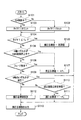
以上のように構成された車両用ブレーキ液圧制御装置100の動作について、本発明の特徴部分を中心に説明する。参照する図において、図4は、車両用ブレーキ液圧制御装置のBA制御の処理を説明するフローチャートである。
The operation of the vehicular brake hydraulic
制御部20は、図4に示すフローチャートに従い、スタートからエンドまでの処理を繰り返し行う。
車両CRが走行中に、BA制御中か否かが判断され、BA制御中でない場合(S101,No)、タイマTをリセットする(S102)。一方、運転者が緊急ブレーキ操作を行い、ブレーキアシストの条件が満たされた場合、BA制御中になるので(S101,Yes)、BA制御手段23は、タイマTをカウントアップする(S103)。
The
While the vehicle CR is traveling, it is determined whether or not the BA control is being performed. If the BA control is not being performed (No in S101), the timer T is reset (S102). On the other hand, when the driver performs an emergency brake operation and the brake assist condition is satisfied, the BA control is in progress (S101, Yes), and the BA control means 23 counts up the timer T (S103).
そして、タイマTが予め記憶していた初期動作期間Tc以下か否か判断し、T≦Tcであった場合(S104,Yes)、BA制御手段23は、調圧目標値に、記憶部29に記憶していた初期値を設定する(S105)。
Then, it is determined whether or not the timer T is equal to or shorter than the initial operation period Tc stored in advance. If T ≦ Tc (Yes in S104), the
一方、T≦Tcではない場合(S104,No)、ステップS106に進み、4つの車輪WのいずれかがABS制御を停止しているか否か判断する。4輪のいずれかがABS制御を停止していた場合は(S106,Yes)、ABS制御に入ってより大きな制動力を得るため、調圧目標値を所定量、例えば差圧でP1に相当する量だけ大きくする(S107,ABS喚起制御)。 On the other hand, if T ≦ Tc is not satisfied (S104, No), the process proceeds to step S106, and it is determined whether any of the four wheels W has stopped the ABS control. If any of the four wheels had stopped the ABS control (S106, Yes), to obtain a greater braking force entered the ABS control, adjusting a predetermined amount pressure target value, corresponding to P 1, for example, differential pressure The amount to be increased is increased (S107, ABS arousing control).
一方、4輪のいずれもがABS制御中であった場合(S106,No)、ステップS108に進み、フェード現象が発生したか否かが判断される。具体的に、ステップS108では、上流側ブレーキ液圧が所定値α以上であり、かつ、入口弁1の駆動電流値が所定値β以下である場合に、フェード現象が発生したと判断し、それ以外の場合に、フェード現象が発生していないと判断する。そして、ステップS108において、フェード現象が発生したと判断された場合には(Yes)、前述したABS喚起制御が実行される(S107)。 On the other hand, when all of the four wheels are under the ABS control (S106, No), the process proceeds to step S108 to determine whether or not a fade phenomenon has occurred. Specifically, in step S108, it is determined that a fade phenomenon has occurred when the upstream brake fluid pressure is greater than or equal to a predetermined value α and the drive current value of the inlet valve 1 is less than or equal to the predetermined value β. Otherwise, it is determined that the fade phenomenon has not occurred. If it is determined in step S108 that a fade phenomenon has occurred (Yes), the ABS arousing control described above is executed (S107).
また、ステップS108において、フェード現象が発生していないと判断された場合には(No)、ステップS109に進み、4つの車輪Wのいずれかが減圧制御に入るか否か判断される。この減圧制御に入るか否かは、図4のフローチャートでは示していない、別のABS制御において決定されるものである。すなわち、ABS制御手段22が、スリップ率に基づいて減圧制御を行うことを決定し、制御弁手段駆動部25aに減圧が指示された場合に、ステップS109において減圧制御に入ると判断される。4輪のいずれかが減圧制御に入ると判断された場合(S109,Yes)、BA制御手段23は、前回の減圧制御と今回の減圧制御の時間的間隔(減圧間隔)が所定時間以下か否か判断する。減圧時間が所定時間以下であった場合(S110,Yes)、頻繁に減圧制御が入っているということであり、吐出液圧路Dの圧力が高すぎることが考えられる。そのため、吐出液圧路Dの圧力を若干下げるべく調圧目標値を所定量、例えば差圧でP2に相当する量だけ小さくする(S111)。
一方、減圧時間が所定時間よりも大きかった場合(S110,No)、またはステップS109の判断において、4輪のいずれもが減圧制御に入る状態でなかったときには、調圧目標値を現状のまま維持する(S112)。
If it is determined in step S108 that the fade phenomenon has not occurred (No), the process proceeds to step S109 to determine whether any of the four wheels W enters pressure reduction control. Whether or not to enter this pressure reduction control is determined in another ABS control not shown in the flowchart of FIG. That is, when the ABS control means 22 decides to perform the pressure reduction control based on the slip ratio and the control valve means driving
On the other hand, if the decompression time is longer than the predetermined time (S110, No), or if all four wheels are not in the state of entering the decompression control in the determination in step S109, the pressure regulation target value is maintained as it is. (S112).
そして、以上の処理により決定された調圧目標値、すなわち調圧弁Rの駆動電流の指示値を調圧弁Rに出力する(S113)。これにより、調圧弁Rに駆動電流が流れ、この駆動電流値に応じた差圧が調圧弁RのマスタシリンダMC側と制御弁手段V(ホイールシリンダH)側の間に形成され、吐出液圧路Dの圧力が調整される。 And the pressure regulation target value determined by the above process, that is, the command value of the drive current of the pressure regulation valve R is output to the pressure regulation valve R (S113). As a result, a drive current flows through the pressure regulating valve R, and a differential pressure corresponding to the drive current value is formed between the master cylinder MC side and the control valve means V (wheel cylinder H) side of the pressure regulating valve R, and the discharge hydraulic pressure The pressure in path D is adjusted.
次に、ABS制御中にフェード現象が発生した場合における制御部20の動作について説明する。参照する図面において、図5は、ABS制御中にフェード現象が発生した場合の車輪速度および車体速度のタイムチャート(a)と、ホイールシリンダ圧とマスタシリンダ圧のタイムチャート(b)と、入口弁の駆動電流のタイムチャート(c)と、調圧目標値のタイムチャート(d)である。
Next, the operation of the
運転者が時刻t0において緊急ブレーキ操作を行うと、マスタシリンダ圧が急上昇することにより緊急ブレーキ操作がなされたと判断され、BA制御が開始される(時刻t1)。ここで、このときのBA制御においては、図5(d)に示すように、調圧目標値が初期値になることにより、この初期値に応じたブレーキ液圧がホイールシリンダHに付与される。 When the driver performs an emergency brake operation at time t0, it is determined that the emergency brake operation has been performed due to a rapid rise in the master cylinder pressure, and BA control is started (time t1). Here, in the BA control at this time, as shown in FIG. 5D, the brake fluid pressure corresponding to the initial value is applied to the wheel cylinder H when the pressure adjustment target value becomes the initial value. .
その後、図5(a)に示すようにスリップ率が所定値以上になり、かつ、車輪加速度が0以下になると(時刻t2)、ABS制御における減圧制御が開始され、図5(b)に示すように、ホイールシリンダ圧が徐々に減少する。その後は、保持、増圧、減圧というようにABS制御が行われることとなる。なお、増圧制御では、入口弁1の駆動電流を、所定勾配で減少させた後(時刻t3〜t4)、この所定勾配よりも緩やかな勾配(時刻t4〜t5)で減少させる制御を行っている。これにより、車輪がロックする直前の高いホイールシリンダ圧を比較的長い時間利用することができ、制動制御の効率の向上が図られている。 After that, as shown in FIG. 5 (a), when the slip ratio becomes equal to or higher than a predetermined value and the wheel acceleration becomes 0 or less (time t2), the pressure reduction control in the ABS control is started, as shown in FIG. 5 (b). As shown, the wheel cylinder pressure gradually decreases. After that, ABS control is performed such as holding, increasing pressure, and decreasing pressure. In the pressure increase control, after the drive current of the inlet valve 1 is decreased at a predetermined gradient (time t3 to t4), control is performed to decrease at a gentler gradient (time t4 to t5) than the predetermined gradient. Yes. As a result, the high wheel cylinder pressure immediately before the wheels are locked can be used for a relatively long time, and the efficiency of braking control is improved.
ここで、従来の車両用ブレーキ液圧制御装置においては、ABS制御中においてフェード現象が発生すると(時刻t6)、ホイールシリンダ圧が限界値(調圧目標値)に達した場合であっても(時刻t7)、制動力が良好に上がらない。これにより、図5(a)の時刻t7以降の破線(車輪速度)で示すように車輪がスリップしない場合がある。この場合、ホイールシリンダ圧は、図5(b)の破線で示すように調圧目標値で一定となる。 Here, in the conventional vehicle brake hydraulic pressure control device, when a fade phenomenon occurs during the ABS control (time t6), even if the wheel cylinder pressure reaches the limit value (pressure regulation target value) ( At time t7), the braking force does not increase well. Thereby, as shown by the broken line (wheel speed) after time t7 in FIG. 5A, the wheel may not slip. In this case, the wheel cylinder pressure is constant at the pressure regulation target value as shown by the broken line in FIG.
これに対し、本実施形態に係る車両用ブレーキ液圧制御装置100では、フェード現象が発生した場合であっても(時刻t6)、ホイールシリンダ圧(上流側ブレーキ液圧)が所定値α以上で、かつ、入口弁1の駆動電流値が所定値β以下となった場合には(時刻t7)、フェード現象が発生したと判定して、図5(d)に示すように調圧目標値を増加させる。これにより制動力(ホイールシリンダ圧)が上がって、図5(a)に示すように、車輪のスリップが発生して、ABS制御の減圧制御が再び開始される(時刻t8)。
In contrast, in the vehicle brake hydraulic
以上によれば、本実施形態において以下のような効果を得ることができる。
入口弁1の上流側ブレーキ液圧が所定値α以上であり、かつ、入口弁1の駆動電流値が所定値β以下である場合(フェード現象が発生したと想定される場合)には、車輪がロック傾向になるような高い液圧値までホイールシリンダ圧を増加することによってABS制御を維持して、操作者の意図した制動力を得ることができ、ブレーキ制御の更なる向上を図ることができる。
According to the above, the following effects can be obtained in the present embodiment.
When the upstream brake fluid pressure of the inlet valve 1 is not less than the predetermined value α and the drive current value of the inlet valve 1 is not more than the predetermined value β (when it is assumed that a fade phenomenon has occurred), the wheel By increasing the wheel cylinder pressure to such a high hydraulic pressure value that tends to lock, the ABS control can be maintained and the braking force intended by the operator can be obtained, thereby further improving the brake control. it can.
入口弁1の駆動電流値を利用して入口弁1の上下流の差圧が所定値以下であるか否かを判定したので、入口弁の上下流のそれぞれに圧力センサを設ける必要がなくなり、コストの低減を図ることができる。 Since it is determined whether or not the differential pressure upstream and downstream of the inlet valve 1 is equal to or less than a predetermined value using the drive current value of the inlet valve 1, it is not necessary to provide pressure sensors on the upstream and downstream sides of the inlet valve. Cost can be reduced.
上流側ブレーキ液圧をマスタシリンダ圧と調圧弁Rの駆動電流値とに基づいて推定することにより、マスタシリンダ圧の検出用の圧力センサ8とは別の圧力センサを入口弁の上流側に設ける必要がないので、コストの低減を図ることができる。
By estimating the upstream brake fluid pressure based on the master cylinder pressure and the drive current value of the pressure regulating valve R, a pressure sensor different from the
なお、本発明は前記実施形態に限定されることなく、以下に例示するように様々な形態で利用できる。 In addition, this invention is not limited to the said embodiment, It can utilize with various forms so that it may illustrate below.
前記実施形態では、入口弁1の駆動電流値と所定値βを比較することで入口弁1の上下流の差圧が所定値以下であるか否かを判定したが、本発明はこれに限定されず、例えば入口弁1の駆動電流値を差圧に換算した後、算出した差圧が所定値以下であるかを判定してもよい。また、入口弁1の上下流の液圧をそれぞれ圧力センサで検出することで、差圧を算出し、この差圧に基づいて判定を行ってもよい。 In the above embodiment, it is determined whether or not the differential pressure upstream and downstream of the inlet valve 1 is equal to or lower than the predetermined value by comparing the driving current value of the inlet valve 1 with the predetermined value β. However, the present invention is limited to this. For example, after the drive current value of the inlet valve 1 is converted into a differential pressure, it may be determined whether the calculated differential pressure is equal to or less than a predetermined value. Further, the differential pressure may be calculated by detecting the upstream and downstream hydraulic pressures with the pressure sensors, and the determination may be performed based on the differential pressure.
前記実施形態では、上流側ブレーキ液圧をマスタシリンダ圧と調圧弁Rの駆動電流値とに基づいて推定したが、本発明はこれに限定されず、入口弁1の上流側に圧力センサを設け、この圧力センサで上流側ブレーキ液圧を検出してもいい。 In the above embodiment, the upstream brake fluid pressure is estimated based on the master cylinder pressure and the drive current value of the pressure regulating valve R. However, the present invention is not limited to this, and a pressure sensor is provided on the upstream side of the inlet valve 1. The upstream brake fluid pressure may be detected by this pressure sensor.
前記実施形態では、BA制御中においてABS制御が実行される場合にフェード判定を行うようにしたが、本発明はこれに限定されず、BA制御が行われていない通常のABS制御時においてフェード判定を行うようにしてもよい。この場合、フェード現象が発生したと判定した場合に、BA制御を実行する(BA制御手段による増圧量を0から所定値まで増加させる)ように制御してもよい。 In the embodiment, the fade determination is performed when the ABS control is executed during the BA control. However, the present invention is not limited to this, and the fade determination is performed during the normal ABS control where the BA control is not performed. May be performed. In this case, when it is determined that a fade phenomenon has occurred, the BA control may be executed (the pressure increase amount by the BA control means is increased from 0 to a predetermined value).
1 入口弁
2 出口弁
4 ポンプ
6 切換弁
20 制御部
21 スリップ率演算部
22 ABS制御手段
23 BA制御手段
25 弁駆動部
25a 制御弁手段駆動部
25b 調圧弁駆動部
25c 吸入弁駆動部
26 モータ駆動部
29 記憶部
30 フェード判定手段
30a 第1判定手段
30b 第2判定手段
31 増圧量変更手段
91 車輪速センサ
100 車両用ブレーキ液圧制御装置
BP ブレーキペダル
FL,FR,RL,RR 車輪ブレーキ
R 調圧弁
DESCRIPTION OF SYMBOLS 1
Claims (2)
車輪ブレーキの上下流に設けられる入口弁および出口弁を制御することで、前記車輪ブレーキ内の液圧を減圧、保持または増圧させるブレーキ液圧制御手段と、を備えた車両用ブレーキ液圧制御装置であって、
前記入口弁の上流側のブレーキ液圧が所定値以上であるか否かを判定する第1判定手段と、
前記入口弁の上下流の差圧が所定値以下であるか否かを判定する第2判定手段と、
前記第1判定手段で前記上流側のブレーキ液圧が所定値以上であると判定され、かつ、前記第2判定手段で前記差圧が所定値以下であると判定されたことを条件として、前記ブレーキアシスト制御手段による増圧量を増加させる増圧量変更手段と、を備え、
前記入口弁は、駆動電流値に応じて上下流の差圧を調整可能な比例電磁弁であり、
前記第2判定手段による判定は、前記入口弁の駆動電流値に基づいて行われることを特徴とする車両用ブレーキ液圧制御装置。 Brake assist control means for determining whether or not brake assist is necessary based on the operating state of the brake operator by the driver, and for increasing the hydraulic pressure in the wheel brake by a pump when it is determined that brake assist is necessary When,
Brake fluid pressure control for vehicles, comprising: brake fluid pressure control means for reducing, holding, or increasing fluid pressure in the wheel brake by controlling inlet and outlet valves provided upstream and downstream of the wheel brake A device,
First determination means for determining whether or not a brake fluid pressure upstream of the inlet valve is equal to or greater than a predetermined value;
Second determination means for determining whether or not a differential pressure upstream and downstream of the inlet valve is equal to or less than a predetermined value;
On the condition that the first determination means determines that the upstream brake fluid pressure is equal to or greater than a predetermined value, and the second determination means determines that the differential pressure is equal to or less than a predetermined value. A pressure increase amount changing means for increasing the pressure increase amount by the brake assist control means ,
The inlet valve is a proportional solenoid valve capable of adjusting the upstream / downstream differential pressure according to the drive current value,
The determination by the second determination means is performed based on a drive current value of the inlet valve .
車輪ブレーキの上下流に設けられる入口弁および出口弁を制御することで、前記車輪ブレーキ内の液圧を減圧、保持または増圧させるブレーキ液圧制御手段と、を備えた車両用ブレーキ液圧制御装置であって、
前記入口弁の上流側のブレーキ液圧が所定値以上であるか否かを判定する第1判定手段と、
前記入口弁の上下流の差圧が所定値以下であるか否かを判定する第2判定手段と、
前記第1判定手段で前記上流側のブレーキ液圧が所定値以上であると判定され、かつ、前記第2判定手段で前記差圧が所定値以下であると判定されたことを条件として、前記ブレーキアシスト制御手段による増圧量を増加させる増圧量変更手段と、を備え、
前記上流側のブレーキ液圧は、
前記ブレーキ操作子の操作状態に応じた液圧を発生するマスタシリンダの液圧と、
前記マスタシリンダと前記入口弁との間の、前記ポンプから液圧が供給される部分よりもマスタシリンダ側の液圧路に配置される比例電磁弁としてのレギュレータの駆動電流値とに基づいて推定されることを特徴とする車両用ブレーキ液圧制御装置。 Brake assist control means for determining whether or not brake assist is necessary based on the operating state of the brake operator by the driver, and for increasing the hydraulic pressure in the wheel brake by a pump when it is determined that brake assist is necessary When,
Brake fluid pressure control for vehicles, comprising: brake fluid pressure control means for reducing, holding, or increasing fluid pressure in the wheel brake by controlling inlet and outlet valves provided upstream and downstream of the wheel brake A device,
First determination means for determining whether or not a brake fluid pressure upstream of the inlet valve is equal to or greater than a predetermined value;
Second determination means for determining whether or not a differential pressure upstream and downstream of the inlet valve is equal to or less than a predetermined value;
On the condition that the first determination means determines that the upstream brake fluid pressure is equal to or greater than a predetermined value, and the second determination means determines that the differential pressure is equal to or less than a predetermined value. A pressure increase amount changing means for increasing the pressure increase amount by the brake assist control means,
The upstream brake fluid pressure is:
The hydraulic pressure of the master cylinder that generates the hydraulic pressure according to the operating state of the brake operator;
Estimated based on a drive current value of a regulator as a proportional solenoid valve arranged in a hydraulic pressure path between the master cylinder and the inlet valve on the master cylinder side of a portion to which hydraulic pressure is supplied from the pump car dual brake fluid pressure control device you characterized in that it is.
Priority Applications (1)
| Application Number | Priority Date | Filing Date | Title |
|---|---|---|---|
| JP2008028378A JP4972575B2 (en) | 2008-02-08 | 2008-02-08 | Brake hydraulic pressure control device for vehicles |
Applications Claiming Priority (1)
| Application Number | Priority Date | Filing Date | Title |
|---|---|---|---|
| JP2008028378A JP4972575B2 (en) | 2008-02-08 | 2008-02-08 | Brake hydraulic pressure control device for vehicles |
Publications (2)
| Publication Number | Publication Date |
|---|---|
| JP2009184587A JP2009184587A (en) | 2009-08-20 |
| JP4972575B2 true JP4972575B2 (en) | 2012-07-11 |
Family
ID=41068288
Family Applications (1)
| Application Number | Title | Priority Date | Filing Date |
|---|---|---|---|
| JP2008028378A Active JP4972575B2 (en) | 2008-02-08 | 2008-02-08 | Brake hydraulic pressure control device for vehicles |
Country Status (1)
| Country | Link |
|---|---|
| JP (1) | JP4972575B2 (en) |
Families Citing this family (2)
| Publication number | Priority date | Publication date | Assignee | Title |
|---|---|---|---|---|
| JP5455969B2 (en) | 2011-05-10 | 2014-03-26 | 日信工業株式会社 | Brake hydraulic pressure control device for vehicles |
| JP6447042B2 (en) * | 2014-11-18 | 2019-01-09 | 株式会社アドヴィックス | Brake device for vehicle |
Family Cites Families (5)
| Publication number | Priority date | Publication date | Assignee | Title |
|---|---|---|---|---|
| JP3287259B2 (en) * | 1996-08-02 | 2002-06-04 | トヨタ自動車株式会社 | Braking force control device |
| JP2000203399A (en) * | 1999-01-18 | 2000-07-25 | Aisin Seiki Co Ltd | Brake control device for vehicle |
| JP2001225740A (en) * | 2000-02-17 | 2001-08-21 | Toyota Motor Corp | Aiding master cylinder and braking control device |
| JP2002137720A (en) * | 2000-10-31 | 2002-05-14 | Aisin Seiki Co Ltd | Brake controlling device for vehicle |
| JP4595941B2 (en) * | 2004-07-08 | 2010-12-08 | トヨタ自動車株式会社 | Vehicle braking force control device |
-
2008
- 2008-02-08 JP JP2008028378A patent/JP4972575B2/en active Active
Also Published As
| Publication number | Publication date |
|---|---|
| JP2009184587A (en) | 2009-08-20 |
Similar Documents
| Publication | Publication Date | Title |
|---|---|---|
| JP4452300B2 (en) | Vehicle behavior control device | |
| JP4473894B2 (en) | Brake hydraulic pressure control device for vehicles | |
| JP5123917B2 (en) | Brake hydraulic pressure control device for vehicles | |
| JP5563004B2 (en) | Brake hydraulic pressure control device for vehicles | |
| JP5632442B2 (en) | Brake hydraulic pressure control device for vehicles | |
| JP4972575B2 (en) | Brake hydraulic pressure control device for vehicles | |
| JP4790744B2 (en) | Brake hydraulic pressure control device for vehicles | |
| JP5022934B2 (en) | Brake pressure holding control device for vehicle | |
| JP5078484B2 (en) | Brake hydraulic pressure control device for vehicles | |
| JP4972481B2 (en) | Brake hydraulic pressure control device for vehicles | |
| JP4555757B2 (en) | Brake hydraulic pressure control device for vehicles | |
| JP4806228B2 (en) | Brake hydraulic pressure control device for vehicles | |
| JP5209589B2 (en) | Brake hydraulic pressure control device for vehicles | |
| JP5245564B2 (en) | Vehicle braking force control device | |
| JP5884239B2 (en) | Brake hydraulic pressure control device for vehicles | |
| JP6091266B2 (en) | Brake hydraulic pressure control device for vehicles | |
| KR100691843B1 (en) | System for controlling the stability of vehicles | |
| JP2005289290A (en) | Brake control system of vehicle | |
| WO2022004442A1 (en) | Vehicle brake fluid pressure control device | |
| JP4913681B2 (en) | Brake hydraulic pressure control device for vehicles | |
| JP5281092B2 (en) | Interlocking brake control device for motorcycle with ABS and control method therefor | |
| JP2009023467A (en) | Brake hydraulic pressure controller for vehicle | |
| JP2009023463A (en) | Brake hydraulic pressure controller for vehicle | |
| JP6091265B2 (en) | Brake hydraulic pressure control device for vehicles | |
| KR100855949B1 (en) | Method for a antilock brake system of a motor vehicle |
Legal Events
| Date | Code | Title | Description |
|---|---|---|---|
| A621 | Written request for application examination |
Free format text: JAPANESE INTERMEDIATE CODE: A621 Effective date: 20100414 |
|
| A977 | Report on retrieval |
Free format text: JAPANESE INTERMEDIATE CODE: A971007 Effective date: 20110616 |
|
| A131 | Notification of reasons for refusal |
Free format text: JAPANESE INTERMEDIATE CODE: A131 Effective date: 20110705 |
|
| A521 | Request for written amendment filed |
Free format text: JAPANESE INTERMEDIATE CODE: A523 Effective date: 20110810 |
|
| TRDD | Decision of grant or rejection written | ||
| A01 | Written decision to grant a patent or to grant a registration (utility model) |
Free format text: JAPANESE INTERMEDIATE CODE: A01 Effective date: 20120327 |
|
| A01 | Written decision to grant a patent or to grant a registration (utility model) |
Free format text: JAPANESE INTERMEDIATE CODE: A01 |
|
| A61 | First payment of annual fees (during grant procedure) |
Free format text: JAPANESE INTERMEDIATE CODE: A61 Effective date: 20120409 |
|
| FPAY | Renewal fee payment (event date is renewal date of database) |
Free format text: PAYMENT UNTIL: 20150413 Year of fee payment: 3 |
|
| R150 | Certificate of patent or registration of utility model |
Free format text: JAPANESE INTERMEDIATE CODE: R150 Ref document number: 4972575 Country of ref document: JP Free format text: JAPANESE INTERMEDIATE CODE: R150 |
|
| R250 | Receipt of annual fees |
Free format text: JAPANESE INTERMEDIATE CODE: R250 |
|
| S111 | Request for change of ownership or part of ownership |
Free format text: JAPANESE INTERMEDIATE CODE: R313113 |
|
| R371 | Transfer withdrawn |
Free format text: JAPANESE INTERMEDIATE CODE: R371 |
|
| R250 | Receipt of annual fees |
Free format text: JAPANESE INTERMEDIATE CODE: R250 |
|
| S111 | Request for change of ownership or part of ownership |
Free format text: JAPANESE INTERMEDIATE CODE: R313111 |
|
| R350 | Written notification of registration of transfer |
Free format text: JAPANESE INTERMEDIATE CODE: R350 |
|
| R250 | Receipt of annual fees |
Free format text: JAPANESE INTERMEDIATE CODE: R250 |
|
| R250 | Receipt of annual fees |
Free format text: JAPANESE INTERMEDIATE CODE: R250 |
|
| R250 | Receipt of annual fees |
Free format text: JAPANESE INTERMEDIATE CODE: R250 |
|
| R250 | Receipt of annual fees |
Free format text: JAPANESE INTERMEDIATE CODE: R250 |
|
| R250 | Receipt of annual fees |
Free format text: JAPANESE INTERMEDIATE CODE: R250 |
|
| R250 | Receipt of annual fees |
Free format text: JAPANESE INTERMEDIATE CODE: R250 |
|
| R250 | Receipt of annual fees |
Free format text: JAPANESE INTERMEDIATE CODE: R250 |
|
| R250 | Receipt of annual fees |
Free format text: JAPANESE INTERMEDIATE CODE: R250 |