EP4487991A2 - Fernpositionierungssystem für holzbearbeitungsmaschinen - Google Patents
Fernpositionierungssystem für holzbearbeitungsmaschinen Download PDFInfo
- Publication number
- EP4487991A2 EP4487991A2 EP24185842.2A EP24185842A EP4487991A2 EP 4487991 A2 EP4487991 A2 EP 4487991A2 EP 24185842 A EP24185842 A EP 24185842A EP 4487991 A2 EP4487991 A2 EP 4487991A2
- Authority
- EP
- European Patent Office
- Prior art keywords
- movable elements
- machine
- positioning
- movable
- pieces
- Prior art date
- Legal status (The legal status is an assumption and is not a legal conclusion. Google has not performed a legal analysis and makes no representation as to the accuracy of the status listed.)
- Pending
Links
Images


Classifications
-
- B—PERFORMING OPERATIONS; TRANSPORTING
- B23—MACHINE TOOLS; METAL-WORKING NOT OTHERWISE PROVIDED FOR
- B23Q—DETAILS, COMPONENTS, OR ACCESSORIES FOR MACHINE TOOLS, e.g. ARRANGEMENTS FOR COPYING OR CONTROLLING; MACHINE TOOLS IN GENERAL CHARACTERISED BY THE CONSTRUCTION OF PARTICULAR DETAILS OR COMPONENTS; COMBINATIONS OR ASSOCIATIONS OF METAL-WORKING MACHINES, NOT DIRECTED TO A PARTICULAR RESULT
- B23Q1/00—Members which are comprised in the general build-up of a form of machine, particularly relatively large fixed members
- B23Q1/03—Stationary work or tool supports
- B23Q1/037—Stationary work or tool supports comprising series of support elements whose relative distance is adjustable
-
- B—PERFORMING OPERATIONS; TRANSPORTING
- B23—MACHINE TOOLS; METAL-WORKING NOT OTHERWISE PROVIDED FOR
- B23Q—DETAILS, COMPONENTS, OR ACCESSORIES FOR MACHINE TOOLS, e.g. ARRANGEMENTS FOR COPYING OR CONTROLLING; MACHINE TOOLS IN GENERAL CHARACTERISED BY THE CONSTRUCTION OF PARTICULAR DETAILS OR COMPONENTS; COMBINATIONS OR ASSOCIATIONS OF METAL-WORKING MACHINES, NOT DIRECTED TO A PARTICULAR RESULT
- B23Q17/00—Arrangements for observing, indicating or measuring on machine tools
- B23Q17/22—Arrangements for observing, indicating or measuring on machine tools for indicating or measuring existing or desired position of tool or work
-
- B—PERFORMING OPERATIONS; TRANSPORTING
- B23—MACHINE TOOLS; METAL-WORKING NOT OTHERWISE PROVIDED FOR
- B23Q—DETAILS, COMPONENTS, OR ACCESSORIES FOR MACHINE TOOLS, e.g. ARRANGEMENTS FOR COPYING OR CONTROLLING; MACHINE TOOLS IN GENERAL CHARACTERISED BY THE CONSTRUCTION OF PARTICULAR DETAILS OR COMPONENTS; COMBINATIONS OR ASSOCIATIONS OF METAL-WORKING MACHINES, NOT DIRECTED TO A PARTICULAR RESULT
- B23Q17/00—Arrangements for observing, indicating or measuring on machine tools
- B23Q17/24—Arrangements for observing, indicating or measuring on machine tools using optics or electromagnetic waves
- B23Q17/2414—Arrangements for observing, indicating or measuring on machine tools using optics or electromagnetic waves for indicating desired positions guiding the positioning of tools or workpieces
-
- B—PERFORMING OPERATIONS; TRANSPORTING
- B27—WORKING OR PRESERVING WOOD OR SIMILAR MATERIAL; NAILING OR STAPLING MACHINES IN GENERAL
- B27M—WORKING OF WOOD NOT PROVIDED FOR IN SUBCLASSES B27B - B27L; MANUFACTURE OF SPECIFIC WOODEN ARTICLES
- B27M1/00—Working of wood not provided for in subclasses B27B - B27L, e.g. by stretching
- B27M1/08—Working of wood not provided for in subclasses B27B - B27L, e.g. by stretching by multi-step processes
-
- G—PHYSICS
- G05—CONTROLLING; REGULATING
- G05B—CONTROL OR REGULATING SYSTEMS IN GENERAL; FUNCTIONAL ELEMENTS OF SUCH SYSTEMS; MONITORING OR TESTING ARRANGEMENTS FOR SUCH SYSTEMS OR ELEMENTS
- G05B19/00—Program-control systems
- G05B19/02—Program-control systems electric
- G05B19/04—Program control other than numerical control, i.e. in sequence controllers or logic controllers
- G05B19/042—Program control other than numerical control, i.e. in sequence controllers or logic controllers using digital processors
Definitions
- the present invention concerns a machine, in particular for working pieces made of wood, ceramic, plastic, glass, fiberglass and the like, equipped with a positioning system and a measurement system.
- the present invention also concerns a positioning system that can be integrated into a machine for working pieces made of wood, ceramic, plastic, glass, fiberglass and the like.
- the present invention also concerns an operating method of said positioning system.
- the invention concerns a positioning and measurement system of the aforementioned type, designed and realized in particular for a numerically controlled working center, in particular for working pieces made of wood, ceramic, plastic, glass, fiberglass and the like, provided with one or more bars, along which movable elements are positioned and slidably coupled for supporting, resting, or fixing of the piece to be worked, in which said bar comprises a mobile supporting base capable of sliding along the working surface.
- Said positioning and measurement system is designed and realized in particular for measuring the position of said movable elements for supporting or fixing the piece along said supporting bar, so as to determine a precise positioning of the piece to which said movable elements are associated, but which can be used for any machine equipped with movable elements capable of providing a reference relating to the pieces to be worked, of which it is necessary to measure the position within the machine, and in particular for points that are difficult to be reached by an operator.
- Working centers which comprise a working surface, on which the pieces to be worked are fixed, and one or more operating groups equipped with working units, capable of having up to 5 interpolating axes, are known.
- the working surface includes a plurality of bars, onto which suction cups or clamps are slidably coupled, suitable for fixing the piece being worked.
- working centers are known, provided with a precision measurement system and equipped with movable elements to hold or fix the wooden panel to be worked, which are manually moved to the desired position communicated to the operator with indicators placed on the movable elements themselves.
- a measurement system is also known, suitable for measuring the position of the suction cups and bars, in communication with a logic control unit, which, knowing the desired position at which to place the suction cups and the bars, emits a signal for the operator for the correct positioning.
- the presence of a pusher can facilitate the movement of said movable elements along a supporting bar.
- the system comprises a plurality of sensors capable of providing the operator with feedback, for example visual or haptic, for the correct positioning of the movable elements along the working surface.
- a further scope of the present invention is to provide the necessary tools for carrying out the method and the apparatus which carry out this method.
- a further scope is to provide a machine for working wooden pieces equipped with said positioning system.
- the specific object of the present invention is a machine for working pieces as defined in claim 1.
- a further specific object of the present invention is a positioning system as defined in the claims.
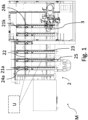
- an operator holds an aid device 25 to move a movable element 24 b along a supporting bar 21 b of a working surface 2 of a machine M for working wooden pieces or similar and positions said movable element 24 b at a specific height based on signals received from a precision positioning system connected to said machine M.
- the precision positioning system is configured to connect to a machine M of the type comprising a logic control unit U that manages its operation and essentially includes a positioning aid device 25 for a plurality of movable elements 24 a,b,...,k,...n on said machine M, which can be functionally connected to said logic control unit U of said machine M.
- the machine M for working wooden pieces in particular a machine for working panels, comprises a base 1 for supporting said machine M, a working surface 2, one or more tools 3, and a logic interface U to manage the operation of the machine M.
- Said one or more tools 3 can comprise an operator group and/or tools for milling, cutting, drilling, or edging operations.
- one or more movable elements 24 a,b,...,k,...n can be manually pushed or pulled along each supporting bar by an operator.
- said system can be integrated into working centers comprising supporting bars 21 a,b,...,k,...n slidably coupled and manually movable by an operator along said base 1, the system can be applied to machines having other configurations of the supporting bars.
- the working surface 2 can comprise, as can be seen from figure 1 , a fixed portion 22, integral with a movable supporting base of said plurality of supporting bars 21 a,b,...,k,...n , along which one or more movable elements are positioned to support or fix the workpiece.
- Each bar of said plurality of supporting bars 21 a,b,...,k,...n can slide on a fixed portion 22 of the working surface 2, to which a tool for working a piece, in particular a panel, is coupled.
- said plurality of supporting bars 21 a,b,...,k,...n can slide along a direction substantially parallel to a X-axis, and said one or more movable elements 24 a,b,...,k,...n is able to slide on each bar, in a direction substantially parallel to a Y-axis.
- said one or more movable elements 24 a,b,...,k,...n can include one or more suction cups, or one or more clamps suitable for fixing the piece being machined and is slidably coupled to one or more supporting bars.
- said plurality of supporting bars 21 a,b,...,k,...n is equipped with ducts for the vacuum supply, necessary to block the pieces to the suction cups.
- One or more movable elements 24 a,b,...,k,...n for example, six suction cups or clamps, which can be removed and then freely repositioned, individually or as a group, based on the machining to be performed on the piece to be worked, can be installed on each bar.
- Each bar of said plurality of supporting bars 21 a,b,...,k,...n can comprise a guide 23 for the manual movement of said plurality of movable elements 24 a,b,...,k,...n .
- a coordinate system XYZ is defined, such that said plurality of supporting bars 21 a,b,...,k,... has a main length along a Y-axis and can slide along said fixed portion 22 integral with an X-axis (fixed portion 22 indicated in figure 1 ).
- Said plurality of movable elements 24 a,b,...,k,...n can be functionally coupled to said logic unit U and to said system by means of a sensor for their measurement and/or positioning.
- the information detected can allow the logic unit U to know the position of said one or more movable elements 24 a,b,...,k,...n, and to inform the operator of the position in which to place said one or more movable elements 24 a,b,...,k,...n .
- detecting the current position of at least one movable element can allow the system defining instructions for the operator to correct the positioning of said element, in particular at distances greater than the length of the operator's arm.
- said precision positioning system is capable of connecting to a measurement system capable of measuring position values of said one or more movable elements 24 a,b,...,k,...n with respect to said plurality of supporting bars 21 a,b,...,k,...n and/or with respect to a specific position, for example saved in said logic control unit U corresponding to a specific configuration of said working surface 2.
- said measurement system is capable of measuring position values of each of said plurality of supporting bars (21 a,b,...,k,...n ).
- said measurement system can comprise a first fixed code, arranged on the base 1, along said fixed portion 22, and a plurality of second codes, or movable codes, each of which is integral with one or more of said supporting bars 21 a,b,...,k,...n , and at least one optical sensor or encoder capable of decoding said codes.
- a fixed code arranged on a fixed portion of said machine M for example on the base 1 or on said fixed portion 22 of the working surface 2 can serve as a static reference for the positioning of the bars along the base 1 itself, and at least one movable code of said plurality of second movable codes, arranged on each bar, allows the detection of the positioning of each suction cup on each supporting bar.
- Said codes can be of binary and/or OR-code type and joined to said machine M, for example, by means of double-sided tape, by magnetic coupling, or by gluing.
- one or more fixed codes are screen-printed on said base and one or more movable codes are screen-printed on each supporting bar and/or applied using an adhesive layer.
- At least one sensor is installed on each supporting bar, capable of detecting a position value of each supporting bar with respect to said one or more fixed codes.
- one or more movable code sensors are installed on the suction cups so as to detect or read a position value of each movable element with respect to a corresponding movable code of a supporting bar.
- the machine M for working pieces comprises one or more movable elements 24 a,b,...,k,...n, each of which is equipped with a position and/or movement sensor, and configured to support and/or hold said pieces to be worked, wherein each of said one or more movable elements is slidably coupled and movable along a respective bar of said plurality of bars 21 a,b,...,k,...n .
- the position and/or movement sensors which each movable element of said movable elements 24 a,b,...,k,...n is equipped with, cooperate with the measurement system of the machine M, of which they are a part, in such a way as to measure position values of said one or more movable elements 24 a,b,...,k....n by reading the fixed and/or movable codes of the measurement system itself.
- said measurement system can include fixed codes and/or movable codes and position and/or movement sensors, for example, integrated in each of said movable elements 24 a,b,...,k,...n , wherein said position and/or movement sensors are capable of measuring the position of the movable elements 24 a,b,...,k,...n with respect to these codes.
- said sensors can be, for example, optical sensors or encoders.
- said optical sensors or encoders can measure the position of the movable elements 24 a,b,...,k,...n at different time instants, said sensors can provide an indication, for example by interpolation, of the movement of said movable elements 24 a,b,...,k,...n .
- each movable code is the same as the other movable codes, therefore each supporting bar is provided with a movable code equal to the code placed, for example, on the adjacent bar (previous or subsequent).
- an additional identification code characteristic of that specific supporting bar can be installed on each supporting bar, so that each movable element can recognize the supporting bar on which it is installed.
- said fixed code can have a longitudinal development along said X-axis from a first reference point, for example an external end of said machine M, to a second reference point, for example coinciding with the coordinate along said X-axis corresponding to the tool 3.
- said measurement system comprises a control unit for receiving, from said logic control unit U, data relating to at least one target position and a real position of a movable device to be compared, as will be described later in this description.
- said logic control unit U can be a unit for managing the operation of said machine M, or a control unit included in said one or more movable elements 24 a,b,...,k,...n , for example, on one or more of the said movable elements.
- said logic control unit U corresponds to the unit for managing the operation of said machine M
- said logic control unit U is programmed, for example, to know or receive the target positions of said movable elements and to receive from the measurement system the real position of each movable device, or at least of a movable device which it is connected with, in such a way as to carry out the comparison between said positions, and in such a way as to communicate, for example by sending signals, with the positioning system aid device.
- the unit for managing the operation of said machine M can be configured to know the target positions of the movable elements, for example the suction cups, and to send said positions, for example sending the coordinates corresponding to said positions, to said control unit on the suction cup, which carries out the comparison between said target positions and the coordinates of the real position of the suction cup and communicates with the auxiliary device of the positioning system, for example, by sending signals or data relating to said comparison.
- Examples of data relating to said comparison comprise one or more configurations of said working surface for machining said pieces to be worked, and position values measured by said measurement system.
- said measurement system control unit allows data to be sent.
- the measurement system control unit communicates the position of the movable element, for example, the suction cup, and/or the position of the supporting bar, with respect to the fixed code detected or the data relating to said survey.
- the measurement system control unit communicates the position of the suction cup with respect to the corresponding supporting bar.
- Examples of data relating to position detection include the indication of the direction in which to move the movable element to reach the desired position. Once said data relating to the position has been received, the logic control unit communicates them to the positioning system, for example to the aid device 25.
- said positioning aid device 25 comprises a proximal end and a distal end.
- said device 25 is particularly advantageous for pushing said one or more movable elements 24 a,b,...,k,...n along each of said plurality of supporting bars 21 a,b,...,k,...n especially when the length of said bars is greater than or equal to 1000 mm.
- the main dimension of the device 25 can be between 500 mm and 3000 mm, preferably between 1000 mm and 1500 mm.
- the device 25 can be sized to reduce the weight and the possible bulk, in which its main dimension is included, for example, between 100 mm and 300 mm, so as to be easily held.
- the device 25 is used for positioning, i.e. to inform the operator of the current positioning of the movable element associated with the device itself, but not to move the movable element.
- said aid device 25 can be worn by the operator.
- Said distal end can be configured to come into contact with at least one of said movable elements 24 a,b,...,k,...n .
- said device 25 can comprise, near its distal end, a connection mechanism for connecting to one or more movable elements 24 a,b,...,k,...n .
- connection mechanism can comprise a magnet, a hook, or a protrusion, for example, substantially perpendicular to the main length of said device 25, to allow pushing and pulling in a controlled manner said one or more movable elements 24 a,b,...,k,...n .
- connection mechanism can prevent the aid device 25 from accidentally deviating from the movable element in movement, for example, while the device pushes the movable element.
- said device 25 can comprise a physical hooking means 252 to hook to an element of said plurality of movable elements 24 a,b,...,k,...n .
- Said physical hooking means 252 can hook one of said movable elements 24 a,b,...,k,...n in response to a change of the position of said element or following the detection of a movement by means of an accelerometer arranged on said movable element.
- said positioning system comprises a radio frequency identification system such that said device 25 comprises a radio frequency reader, for example an RFID reader, capable of reading one or more radio frequency labels (tags) arranged on said movable elements 24 a,b,...,k,...n , in such a way that said physical hooking means 252 hooks one of said movable elements 24 a,b,...,k,...n , when said movable element is positioned near the device 25 and the reader detects its proximity.
- a radio frequency identification system such that said device 25 comprises a radio frequency reader, for example an RFID reader, capable of reading one or more radio frequency labels (tags) arranged on said movable elements 24 a,b,...,k,...n , in such a way that said physical hooking means 252 hooks one of said movable elements 24 a,b,...,k,...n , when said movable element is positioned near the device 25 and the reader detects its proximity.
- said hooking means 252 can also comprise a plurality of fins, for example two, which extends from the distal end of the device 25 to rest on at least one movable element 24 b .
- said positioning aid device 25 can comprise a handle 251 arranged near said proximal end configured to be handled by an operator.
- Said device 25 can comprise at least one communication means capable of communicating with said one or more movable elements 24 a,b,...,k,...n and/or at least a signaling means 251' to inform an operator of the positioning of one of said one or more movable elements 24 a,b,...,k,...n .
- Said communication means may comprise a radio, optical, and/or serial communication interface.
- the communication between said device 25 and said plurality of movable elements 24 a,b,...,k,...n and/or said logic unit U occurs via a radio communication interface or a reception and transmission module in wireless or radio mode, for example, Zigbee, Wi-Fi, or Bluetooth. In this way, it is possible to obtain a low-cost and clutter-free connection.
- Further communication means include at least one serial communication interface, for example, rs232, canopen, or modbus type.
- communication may occur via infrared radiation.
- Said signaling means 251' can comprise an indicator with optical feedback, with haptic feedback, and/or a screen on which representing the information relating to the positioning of the suction cups and/or bars, to be reported to the operator.
- Haptic feedback for example by means of a vibration having a plurality of intensities, can facilitate the operator to ensure that the positioning is correct.
- the vibration can signal whether the positioning is correct and the optical feedback can signal the direction to follow to correct the positioning of said one or more movable elements 24 a,b,...,k,...n .
- said positioning aid device 25 can comprise a local logic unit capable of communicating with said (global) logic unit U of said machine M and/or capable of communicating with each of said one or more movable elements 24 a,b,...,k,...n and/or capable of communicating with said measurement system control unit.
- said precision positioning system can be coupled to a measurement system capable of measuring position values of said one or more movable elements 24 a,b,...,k,...n with respect to said plurality of supporting bars 21 a,b,...,k,...n and/or with respect to a specific position, for example saved in said logic control unit U corresponding to a specific configuration of said working surface2.
- the measurement system then sends said position values to said logic control unit U.
- said logic control unit U can carry out a comparison between said stored configurations and said received position values and send corresponding signals to said system, which makes them available to the operator to manually move said plurality of supporting bars 21 a,b,...,k,...n and/or said one or more movable elements 24 a,b,...,k,...n .
- the signals corresponding to the position to be reached and the accuracy of the positioning are sent by the system to the operator via indicators present on said device 25 to assist in the positioning of said plurality of movable elements 24 a,b,...,k,...n .
- the operation comprises the definition of a height or space from a reference point on which to position one or more movable elements 24 a,b,...,k,...n with respect to said working surface 2.
- Said definition of the quota can be saved beforehand in said logic unit U or entered manually by an operator.
- the coordinates of the movable elements and/or supporting bars corresponding to one or more configurations of said working surface 2 for working said pieces are stored in said logic unit U.
- the measurement system coupled to the working surface 2, as will be described later, is capable of measuring position values of the supporting bars 21 a,b,...,k,...n and movable elements 24 a,b,...,k,...n and send them to the logic unit U. Once these position values have been received, the logic unit U carries out a comparison between said stored configurations and said received position values and sends the position values to the aid device 25, which emits signals corresponding to this comparison.
- the comparison between a configuration of the working surface 2 for working the pieces and the received position values, for example, the received coordinates, is ensured by the fact that the stored configurations include the coordinates of the movable elements and/or of the supporting bars, relating to each working of the pieces.
- a height at which said movable element is positioned is detected or measured with respect to said working surface 2.
- This detection can take place via a camera arranged on each element of said plurality of movable elements or via sensors present in said positioning aid device 25, once said device 25 has been coupled, mechanically or electronically, to one or more movable elements.
- each of said movable elements 24 a,b,...,k,...n comprises a control unit equipped with at least one movement or acceleration detector, for example, an accelerometer, and a communication circuit.
- the control unit activates the communication of the data detected by the movement or acceleration detector.
- the accelerometer detects the data referring to the movement of said activated movable element and the communication circuit sends such data to the logic control unit U, which receives the data detected by the accelerometer referring to the element that moved, communicates it to the aid device 25, which is associated with said movable element in movement.
- the aid device 25 is associated with the only movable element in movement, while the other movable elements 24 a,b,...,k,...n are not moved.
- the accelerometer detects its movement and the communication circuit sends the acceleration data detected directly to the aid device 25, which is associated with said movable element in movement.
- the information detected by an accelerometer on said plurality of movable elements 24 a,b,...,k,...n is sent to the positioning system by the logic unit U of the machine M, which has previously processed them or directly by said one or more movable elements 24 a,b,...,k,...n via, for example, a radio connection.
- the positioning system can calculate or measure a distance between said detected quota and said defined quota of said movable element of said plurality of movable elements 24 a,b,...,k,...n with respect to said working surface 2.
- the positioning system may comprise an integrated local logic unit, which performs the calculation and information transmission operations.
- the system is capable of informing, through said aid device 25 functionally connected to a logic unit U, an operator to correct the positioning of each of said one or more movable elements 24 a,b,...,k,...n and minimize the distance between said detected height and said defined height.
- the system can detect a movement of one or more movable elements 24 a,b,...,k,...n by means of a detector, for example, an accelerometer, with which said one or more movable elements are equipped.
- a detector for example, an accelerometer
- the system interacts with the detectors of a single movable element that, with its movement, has activated a detector with which it is equipped.
- the system can detect a contact between a movable element and said positioning aid device 25. This combination is advantageous when the operator realizes that said movable element is not in the correct position, but requires a guide to adequately correct said positioning. Therefore, the operator can hook the element with the device 25 and wait for instructions from the system.
- said system can detect one or more movable elements 24 a,b,...,k,...n in correspondence with said positioning aid device 25.
- the system is capable of detecting the movable element and determine whether it is necessary to correct its positioning before the physical hooking with the device 25.
- An advantage of the present invention provides for the presence of a machine for working wooden pieces, equipped with a positioning system and a measurement system of one or more movable elements used for supporting or fixing the pieces to be worked.
- a further advantage of the present invention provides for the presence of a positioning system which allows the movable elements for supporting or fixing the piece to be positioned with less uncertainty at a given height on a supporting bar of a machine for working wooden pieces or the like by means of a mechanical positioning means which includes sensors and indicators to inform the operator on the operations to be performed.
- a further advantage of the invention is given by the presence of a plurality of sensors capable of providing the operator with feedback for the correct positioning of the movable elements along the working surface.
- Another advantage is to provide a system for precision positioning of movable elements that can be connected to a machine having one or more movable elements equipped with position and/or movement sensors.
- the positioning system of the present invention allows the operator to know whether a movable supporting, fixing, or stopping element of the piece is in the correct position and also to provide easy-to-read indications to the operator for moving said element.
Landscapes
- Engineering & Computer Science (AREA)
- Mechanical Engineering (AREA)
- Physics & Mathematics (AREA)
- Life Sciences & Earth Sciences (AREA)
- General Physics & Mathematics (AREA)
- Automation & Control Theory (AREA)
- Wood Science & Technology (AREA)
- Forests & Forestry (AREA)
- Optics & Photonics (AREA)
- Length Measuring Devices With Unspecified Measuring Means (AREA)
- Control Of Position Or Direction (AREA)
Applications Claiming Priority (1)
| Application Number | Priority Date | Filing Date | Title |
|---|---|---|---|
| IT102023000014172A IT202300014172A1 (it) | 2023-07-06 | 2023-07-06 | Sistema di posizionamento remoto per macchine per la lavorazione di pezzi in legno |
Publications (2)
| Publication Number | Publication Date |
|---|---|
| EP4487991A2 true EP4487991A2 (de) | 2025-01-08 |
| EP4487991A3 EP4487991A3 (de) | 2025-03-05 |
Family
ID=88207064
Family Applications (1)
| Application Number | Title | Priority Date | Filing Date |
|---|---|---|---|
| EP24185842.2A Pending EP4487991A3 (de) | 2023-07-06 | 2024-07-01 | Fernpositionierungssystem für holzbearbeitungsmaschinen |
Country Status (2)
| Country | Link |
|---|---|
| EP (1) | EP4487991A3 (de) |
| IT (1) | IT202300014172A1 (de) |
Family Cites Families (3)
| Publication number | Priority date | Publication date | Assignee | Title |
|---|---|---|---|---|
| IT1270691B (it) * | 1994-11-03 | 1997-05-07 | "maccina utensile per la lavorazione di pannelli e lastre." | |
| EP3696631B1 (de) * | 2019-02-13 | 2023-04-05 | SCM Group S.p.A. | Bearbeitungszentrum mit einem messsystem zur bearbeitung von holzstücken |
| DE202021105854U1 (de) * | 2021-10-26 | 2021-11-29 | Holz-Her Gmbh | Werkstückaufspannvorrichtung und Holzbearbeitungsmaschine mit einer Werkstückaufspannvorrichtung |
-
2023
- 2023-07-06 IT IT102023000014172A patent/IT202300014172A1/it unknown
-
2024
- 2024-07-01 EP EP24185842.2A patent/EP4487991A3/de active Pending
Also Published As
| Publication number | Publication date |
|---|---|
| EP4487991A3 (de) | 2025-03-05 |
| IT202300014172A1 (it) | 2025-01-06 |
Similar Documents
| Publication | Publication Date | Title |
|---|---|---|
| CN107303643B (zh) | 机床的误差辨识方法及误差辨识系统 | |
| CN112683215B (zh) | 提供关于坐标测量机传感器链的信息的方法、坐标测量机 | |
| NL2008435C2 (en) | An apparatus for pointing spatial coordinates, comprising a movable hand-held probe and a portable base unit, and a related method. | |
| JPH0262162B2 (de) | ||
| US20030090682A1 (en) | Positioning in computer aided manufacturing by measuring both parts (cameras, retro reflectors) | |
| US20080072444A1 (en) | Vehicle dimensional measuring system | |
| CN102189420B (zh) | 机床和在机床中测定工件夹持装置中夹紧的工件位置的方法 | |
| EP1128156A1 (de) | Verfahren und Vorrichtung zur automatischen Kompensation von Messfehlern | |
| EP3696631B1 (de) | Bearbeitungszentrum mit einem messsystem zur bearbeitung von holzstücken | |
| CN107044837B (zh) | 用于标定检测工具坐标系的方法、装置以及控制设备 | |
| US5996239A (en) | Method of making coordinate measurements of a workpiece on a machine tool | |
| EP3020521A1 (de) | Bordmesssystem für gehrungssägen | |
| KR102460118B1 (ko) | 어태치먼트 중심위치의 보정방법 | |
| US7460970B2 (en) | Method and device for measuring workpieces with a measuring probe on a machine tool | |
| US12259707B2 (en) | Device for monitoring the position and/or attitude and/or movement of a tool | |
| US20150066195A1 (en) | Method for positioning a tool of a machine tool in the visual field of a visual system and relative machine tool | |
| KR100750897B1 (ko) | 실내 위치측정시스템을 이용한 3차원 측정 시스템 및리스케일 방법 | |
| CN112775720B (zh) | 机床的对象物的位置测量方法及位置测量系统、计算机可读记录介质 | |
| EP4487991A2 (de) | Fernpositionierungssystem für holzbearbeitungsmaschinen | |
| CN109839075A (zh) | 一种机器人自动测量系统及测量方法 | |
| WO2012101608A1 (en) | Machine for machining components made of wood or the like | |
| US12070827B2 (en) | Control mechanism, tool replacement equipment and tool replacement method | |
| WO2002097362A1 (en) | Photogrammetry targets | |
| EP1457289A1 (de) | Vorrichtung zum Kontrollieren der Position einer Spindel in einer Werkzeugmaschine | |
| US8442679B2 (en) | Method and device for handling an object with the aid of a location system |
Legal Events
| Date | Code | Title | Description |
|---|---|---|---|
| PUAI | Public reference made under article 153(3) epc to a published international application that has entered the european phase |
Free format text: ORIGINAL CODE: 0009012 |
|
| STAA | Information on the status of an ep patent application or granted ep patent |
Free format text: STATUS: THE APPLICATION HAS BEEN PUBLISHED |
|
| AK | Designated contracting states |
Kind code of ref document: A2 Designated state(s): AL AT BE BG CH CY CZ DE DK EE ES FI FR GB GR HR HU IE IS IT LI LT LU LV MC ME MK MT NL NO PL PT RO RS SE SI SK SM TR |
|
| PUAL | Search report despatched |
Free format text: ORIGINAL CODE: 0009013 |
|
| AK | Designated contracting states |
Kind code of ref document: A3 Designated state(s): AL AT BE BG CH CY CZ DE DK EE ES FI FR GB GR HR HU IE IS IT LI LT LU LV MC ME MK MT NL NO PL PT RO RS SE SI SK SM TR |
|
| RIC1 | Information provided on ipc code assigned before grant |
Ipc: G05B 19/00 20060101ALI20250127BHEP Ipc: B27M 1/08 20060101ALI20250127BHEP Ipc: B23Q 17/24 20060101ALI20250127BHEP Ipc: B23Q 17/22 20060101ALI20250127BHEP Ipc: B23Q 1/03 20060101AFI20250127BHEP |
|
| STAA | Information on the status of an ep patent application or granted ep patent |
Free format text: STATUS: REQUEST FOR EXAMINATION WAS MADE |
|
| 17P | Request for examination filed |
Effective date: 20250825 |