EP4487703A1 - Atomizer and electronic atomization device - Google Patents
Atomizer and electronic atomization device Download PDFInfo
- Publication number
- EP4487703A1 EP4487703A1 EP23778478.0A EP23778478A EP4487703A1 EP 4487703 A1 EP4487703 A1 EP 4487703A1 EP 23778478 A EP23778478 A EP 23778478A EP 4487703 A1 EP4487703 A1 EP 4487703A1
- Authority
- EP
- European Patent Office
- Prior art keywords
- heating element
- holder
- atomizer
- support part
- heating
- Prior art date
- Legal status (The legal status is an assumption and is not a legal conclusion. Google has not performed a legal analysis and makes no representation as to the accuracy of the status listed.)
- Pending
Links
Images




Classifications
-
- A—HUMAN NECESSITIES
- A24—TOBACCO; CIGARS; CIGARETTES; SIMULATED SMOKING DEVICES; SMOKERS' REQUISITES
- A24F—SMOKERS' REQUISITES; MATCH BOXES; SIMULATED SMOKING DEVICES
- A24F40/00—Electrically operated smoking devices; Component parts thereof; Manufacture thereof; Maintenance or testing thereof; Charging means specially adapted therefor
- A24F40/40—Constructional details, e.g. connection of cartridges and battery parts
- A24F40/46—Shape or structure of electric heating means
-
- A—HUMAN NECESSITIES
- A24—TOBACCO; CIGARS; CIGARETTES; SIMULATED SMOKING DEVICES; SMOKERS' REQUISITES
- A24F—SMOKERS' REQUISITES; MATCH BOXES; SIMULATED SMOKING DEVICES
- A24F40/00—Electrically operated smoking devices; Component parts thereof; Manufacture thereof; Maintenance or testing thereof; Charging means specially adapted therefor
- A24F40/10—Devices using liquid inhalable precursors
-
- A—HUMAN NECESSITIES
- A24—TOBACCO; CIGARS; CIGARETTES; SIMULATED SMOKING DEVICES; SMOKERS' REQUISITES
- A24F—SMOKERS' REQUISITES; MATCH BOXES; SIMULATED SMOKING DEVICES
- A24F40/00—Electrically operated smoking devices; Component parts thereof; Manufacture thereof; Maintenance or testing thereof; Charging means specially adapted therefor
- A24F40/40—Constructional details, e.g. connection of cartridges and battery parts
-
- A—HUMAN NECESSITIES
- A24—TOBACCO; CIGARS; CIGARETTES; SIMULATED SMOKING DEVICES; SMOKERS' REQUISITES
- A24F—SMOKERS' REQUISITES; MATCH BOXES; SIMULATED SMOKING DEVICES
- A24F40/00—Electrically operated smoking devices; Component parts thereof; Manufacture thereof; Maintenance or testing thereof; Charging means specially adapted therefor
- A24F40/40—Constructional details, e.g. connection of cartridges and battery parts
- A24F40/42—Cartridges or containers for inhalable precursors
-
- A—HUMAN NECESSITIES
- A24—TOBACCO; CIGARS; CIGARETTES; SIMULATED SMOKING DEVICES; SMOKERS' REQUISITES
- A24F—SMOKERS' REQUISITES; MATCH BOXES; SIMULATED SMOKING DEVICES
- A24F40/00—Electrically operated smoking devices; Component parts thereof; Manufacture thereof; Maintenance or testing thereof; Charging means specially adapted therefor
- A24F40/40—Constructional details, e.g. connection of cartridges and battery parts
- A24F40/44—Wicks
-
- A—HUMAN NECESSITIES
- A24—TOBACCO; CIGARS; CIGARETTES; SIMULATED SMOKING DEVICES; SMOKERS' REQUISITES
- A24F—SMOKERS' REQUISITES; MATCH BOXES; SIMULATED SMOKING DEVICES
- A24F40/00—Electrically operated smoking devices; Component parts thereof; Manufacture thereof; Maintenance or testing thereof; Charging means specially adapted therefor
- A24F40/40—Constructional details, e.g. connection of cartridges and battery parts
- A24F40/48—Fluid transfer means, e.g. pumps
- A24F40/485—Valves; Apertures
-
- A—HUMAN NECESSITIES
- A24—TOBACCO; CIGARS; CIGARETTES; SIMULATED SMOKING DEVICES; SMOKERS' REQUISITES
- A24F—SMOKERS' REQUISITES; MATCH BOXES; SIMULATED SMOKING DEVICES
- A24F40/00—Electrically operated smoking devices; Component parts thereof; Manufacture thereof; Maintenance or testing thereof; Charging means specially adapted therefor
- A24F40/50—Control or monitoring
- A24F40/51—Arrangement of sensors
-
- A—HUMAN NECESSITIES
- A24—TOBACCO; CIGARS; CIGARETTES; SIMULATED SMOKING DEVICES; SMOKERS' REQUISITES
- A24F—SMOKERS' REQUISITES; MATCH BOXES; SIMULATED SMOKING DEVICES
- A24F40/00—Electrically operated smoking devices; Component parts thereof; Manufacture thereof; Maintenance or testing thereof; Charging means specially adapted therefor
- A24F40/70—Manufacture
Definitions
- Embodiments of this application relate to the field of electronic atomization technologies, and in particular, to an atomizer and an electronic atomization device.
- Tobacco products for example, cigarettes and cigars
- tobacco-burning products by manufacturing products that release compounds without being burnt.
- the products is a heating device that releases a compound by heating rather than burning a material.
- the material may be tobacco or other non-tobacco products. These non-tobacco products may or may not include nicotine.
- electronic atomization devices These devices generally include a liquid, and the liquid is heated to vaporize, to generate an inhalable aerosol.
- the liquid may contain nicotine, and/or aromatics, and/or aerosol-generation substances (such as glycerin).
- a heating mesh wound into a cylindrical shape is wrapped, surrounded, and supported from the outside by an annular liquid guide element, so that the heating mesh is stably retained in the electronic atomization device.
- an atomizer including:
- the heating element is made by a sheet material wound around at least a part of the holder.
- the atomizer further includes:
- the holder includes a first part surrounded by the heating element and a second part exposed outside the heating element, the first part is configured to provide support for the heating element from the inside of the heating element, and the second part abuts against the heating element to provide stop.
- the atomizer further includes: a liquid guide element, extending along an axial direction of the heating element and surrounding the heating element, and configured to conduct the liquid substrate in the liquid storage cavity to the heating element.
- the atomizer further includes: a tubular element, extending along the longitudinal direction of the atomizer, and at least partially defining the liquid storage cavity, where the tubular element is constructed to surround and retain the liquid guide element and abut against the holder to be stopped.
- the liquid guide element is flexible, and is at least partially radially squeezed or compressed between the tubular element and the heating element.
- the tubular element is provided with a first notch, groove, or hole; and the holder is provided with a positioning clamping protrusion extending into the first notch, groove, or hole, to prevent the tubular element from rotating relative to the holder.
- the heating element includes a first end and a second end facing away from each other along an axial direction;
- the heating element defines a side opening extending along an axial direction, to enable the heating element to be non-closed along a circumferential direction.
- the holder further includes a third support part extending along the longitudinal direction, and the third support part is at least partially located in the side opening of the heating element, to provide support for the heating element.
- the heating element includes a conductive lead for supplying power to the heating element; and an inner surface or an outer surface of the holder is provided with a lead groove, and the conductive lead is at least partially accommodated and retained in the lead groove.
- the atomizer further includes: a lead fastener, at least partially shielding or covering the conductive lead accommodated in the lead groove, to prevent the conductive lead from leaving the lead groove.
- the lead fastener is substantially constructed in an annular shape.
- the liquid storage cavity is provided with an open end
- the atomizer further includes: a flexible sealing base, configured to cover the open end to seal the liquid storage cavity, where the sealing base accommodates and retains at least a part of the holder.
- the atomizer further includes:
- the air channel includes an air groove provided on an outer surface of the extension arm and/or an inner surface of the through hole.
- the heating element includes a first end and a second end facing away from each other along an axial direction, and the heating element further includes:
- the heating element includes a first end and a second end facing away from each other along an axial direction, and the heating element further includes:
- an embodiment of this application further provides another atomizer, including:
- the end support member may be an end cap component of the atomizer.
- an embodiment of this application further provides an electronic atomization device, including an atomizer configured to atomize a liquid substrate to generate an aerosol, and a power supply device configured to supply power to the atomizer.
- the atomizer includes the atomizer described above.
- the holder at least partially extends into the cylindrical heating element, to provide support for the heating element.
- the electronic atomization device includes an atomizer 100 for storing a liquid substrate and atomizing the liquid substrate to generate an aerosol, and a power supply mechanism 200 for supplying power to the atomizer 100.
- the power supply mechanism 200 includes: a receiving cavity 270, arranged on an end along a length direction and configured to receive and accommodate at least a part of the atomizer 100; and a first electrical contact 230, at least partially exposed in the receiving cavity 270, configured to be electrically connected to the atomizer 100 to supply power to the atomizer 100 when at least a part of the atomizer 100 is received and accommodated in the power supply mechanism 200.
- a second electrical contact 21 is arranged on an end portion of the atomizer 100 opposite to the power supply mechanism 200 along the length direction, so that when at least a part of the atomizer 100 is received in the receiving cavity 270, the second electrical contact 21 is in contact with and abuts against the first electrical contact 230 to conduct electricity.
- a seal element 260 is arranged in the power supply mechanism 200, and at least a part of an internal space of the power supply mechanism 200 is separated through the seal element 260 to form the receiving cavity 270.
- the sealing member 260 is constructed to extend along a longitudinal direction perpendicular to the power supply mechanism 200, and is preferably made by a flexible material such as silica gel, to prevent the liquid substrate seeping from the atomizer 100 to the receiving cavity 270 from flowing to a controller 220, a sensor 250, and other components inside the power supply mechanism 200.
- the power supply mechanism 200 further includes: a battery cell 210, located at another end facing away from the receiving cavity 270 along a length direction, and configured to supply power; and a controller 220, arranged between the battery cell 210 and the receiving cavity 270, and the controller 220 operably guides a current between the battery cell 210 and the first electrical contact 230.
- the power supply mechanism 200 includes a sensor 250, configured to sense an inhalation flow generated by the atomizer 100 during inhalation, so that the controller 220 controls the battery cell 210, based on a detection signal of the sensor 250, to supply power to the atomizer 100.
- a charging interface 240 is arranged on another end of the power supply mechanism 200 facing away from the receiving cavity 270, and is configured to supply power to the battery cell 210.
- the embodiments in FIG. 2 to FIG. 5 are schematic structural diagrams of the atomizer 100 in FIG. 1 according to an embodiment.
- the atomizer 100 includes: a main housing 10. As shown in FIG. 2 to FIG. 3 , the main housing 10 is substantially in a flat cylindrical shape.
- the main housing 10 has a proximal end 110 and a distal end 120 opposite to each other along a length direction.
- the proximal end 110 is configured as an end for a user to inhale an aerosol.
- the proximal end 110 is provided with an inhalation port A for the user to inhale.
- the distal end 120 is used as an end combined with the power supply mechanism 200.
- the distal end 120 of the main housing 10 is an open end on which a detachable end cap 20 is mounted.
- the open end structure is configured to mount necessary functional components inside the main housing 10.
- the second electrical contact 21 penetrates into the atomizer 100 from a surface of the end cap 20, to at least partially exposed on the end cap 20/atomizer 100/distal end 120.
- the second electrical contact 21 may be in contact with the first electrical contact 230 to conduct electricity.
- the end cap 20 is further provided with a first air inlet 23 for external air to enter into the atomizer 100 during inhalation.
- the interior of the main housing 10 is provided with a liquid storage cavity 12 configured to store the liquid substrate and an atomization assembly configured to absorb the liquid substrate from the liquid storage cavity 12 and heat and atomize the liquid substrate.
- the atomization assembly generally includes a capillary liquid guide element 30 configured to absorb the liquid substrate and a heating element 40 combined on the liquid guide element 30.
- the heating element 40 heats at least a part of the liquid substrate of the liquid guide element 30 during energization, to generate the aerosol.
- the liquid guide element 30 includes flexible fibers, such as cotton fibers, non-woven fabrics, or fiberglass cords, or includes porous materials with a microporous structure, for example, porous ceramics.
- the heating element 40 may be combined on the liquid guide element 30 by printing, deposition, sintering, or physical assembly, or wound around the liquid guide element 30.
- the interior of the main housing 10 is provided with an air tube 13 extending from the proximal end 110 toward the distal end 120 and a tubular element 11 extending along the longitudinal direction, spaced apart from the air tube 13, and connected to the air tube 13.
- the air tube 13 and the tubular element 11 jointly define an output channel for outputting the aerosol.
- the tubular element 11 is an independent component, and is preferably made of a thin rigid material, such as ceramic or stainless steel.
- the air tube 13 is integrally molded with the main housing 10 by using a moldable material.
- the liquid storage cavity 12 configured to store the liquid substrate is defined between an outer surface of the air tube 13, an outer surface of the tubular element 11, and an inner wall of the main housing 10, that is, the tubular element 11 at least partially defines the liquid storage cavity 12.
- the liquid storage cavity 12 defined in the main housing 10 is closed by the main housing 10 at the proximal end 110.
- An end portion of the liquid storage cavity 12 toward the distal end 120 is open.
- the atomizer 100 further includes: a flexible sealing base 60, configured to close the open end of the liquid storage cavity 12 toward the distal end 120, and configured to provide sealing between the end cap 20 and the main housing 10, to prevent the liquid substrate from seeping out.
- the flexible sealing base 60 includes: a peripheral side wall 610 and a sealing part 620 located in the peripheral side wall 610.
- the spacing space 630 is open toward a side facing the end cap 20.
- the end cap 20 is inserted into or extends into the spacing space 630 for assembly.
- the peripheral side wall 610 partially surrounds or encloses the end cap 20, and is supported by the end cap 20 from the inside, to provide sealing between the end cap 20 and the main housing 10.
- the sealing part 620 extends into or is accommodated in the end cap 20.
- the sealing base 60 is provided with a contact hole 62 penetrating into the sealing base along an axial direction or a longitudinal direction.
- the second electrical contact 21 penetrates into or extends into the contact hole 62.
- the second electrical contact 21 extends to the liquid storage cavity 12 after penetrating into the contact hole 62.
- the second electrical contact 21 is flush with a surface of the sealing base 60. The second electrical contact 21 does not protrude or recess relative to the surface of the sealing base 60.
- the tubular element 11 is assembled with an atomization assembly, and the tubular element 11 is provided with several liquid guide holes 111 spaced apart along the circumferential direction, for the liquid storage cavity 12 to enter. Therefore, the atomization assembly is in fluid communication with the liquid storage cavity 12 through the liquid guide hole 111 to receive the liquid substrate.
- the atomization assembly includes: the liquid guide element 30, flexible in the embodiments, for example, made of flexible fibers such as cotton fibers, non-woven fabrics, or sponges.
- the liquid guide element 30 is constructed in an annular shape arranged along the longitudinal direction of the main housing 10.
- the liquid guide element 30 is coaxial with the tubular element 11 and located in the tubular element 11.
- an outer surface of the liquid guide element 30 along a radial direction blocks or communicates with the liquid guide hole 111, so that the outer surface of the liquid guide element 30 is configured as a liquid absorbing surface, to receive and absorb the liquid substrate in the liquid storage cavity 12 through the liquid guide hole 111.
- An inner surface of the liquid guide element 30 along the radial direction is configured as an atomization surface, and the atomization surface is combined with/attached to/abuts against the heating element 40, so that after being transferred to the atomization surface, the liquid substrate is heated and atomized by the heating element 40 to generate and release the aerosol.
- the liquid guide element 30 extends along the axial direction of the heating element 40 and surrounds the heating element 40, and is configured to conduct the liquid substrate in the liquid storage cavity 12 to the heating element 40.
- the heating element 40 is constructed to extend along the longitudinal direction of the main housing 10/liquid guide element 30.
- the heating element 40 is arranged co-axially with the liquid guide element 30.
- the heating element 40 is a resistive heating mesh, a resistive heating coil, or the like.
- the heating element 40 is a heating element wound by a sheet-shaped or mesh-shaped substrate, that is, the heating element 40 is wound by a sheet material.
- the wound heating element 40 is in a non-closed tubular shape along the circumferential direction, and is in a cylindrical shape with a side opening 45 along the longitudinal direction.
- the heating element 40 includes electrode parts 41 located at two sides of the side opening 45, a mesh-shaped resistive heating part 42 extending between the electrode parts 41, and conductive leads 43 connected to the electrode parts 41. It is cleared that, there are two electrode parts 41 and two conductive leads 43, one being used as a positive end and the other being used as a negative end.
- the resistive heating part 42 is in a mesh shape with mesh holes.
- the electrode parts 41 have no mesh holes.
- the heating element 40 is wound or fixed on the holder 50.
- the sealing base 60 is further provided with a holder hole 61 penetrating into the sealing base 60 along the longitudinal direction.
- the holder 50 is accommodated or mounted in the holder hole 61. It is cleared that, in a conventional embodiment, an inner diameter of the holder hole 61 is non-constant. Specifically, an inner diameter of the holder hole 61 close to the distal end 120 is less than an inner diameter away from the distal end 120. Therefore, there is an abutting step in the holder hole 61. After assembly, the holder 50 extends into the holder hole 61 from a side close to the liquid storage cavity 12 and then abuts against the step to form stop.
- a shape or a structure of the holder 50 includes: a support part 51, a support part 52, a support part 53, a support part 54, and a support part 55 arranged along the axial direction sequentially.
- the support part 51, the support part 53, the support part 54, and the support part 55 are all constructed in annular shapes, and are co-axially arranged.
- the support part 51 and the support part 53 have a same outer diameter and/or inner diameter.
- An outer diameter of the support part 54 is greater than an outer diameter of the support part 53, and an outer diameter of the support part 55 is greater than the outer diameter of the support part 54.
- the support part 54 provides stop for the heating element 40.
- the support part 51, the support part 52, and the support part 53 may be first parts, and the support part 54 and the support part 55 may be second parts.
- the holder 50 includes a first part surrounded by the heating element 40 and a second part exposed outside the heating element 40. The first part is configured to provide support for the heating element 40 from the inside of the heating element 40, and the second part abuts against the heating element 40 to provide stop.
- the heating element 40 surrounds the first part, the heating element is made of a sheet material wound around the first part of the holder 50, that is, the heating element 40 is made of the sheet material wound around at least a part of the holder 50.
- the support part 52 is an elongated shape extending along an axial direction of the holder 50, rather than an annular shape, and is further configured to connect the support part 51 to the support part 53 in addition to providing support.
- the holder 50 is made of an electrically insulating rigid material, for example, ceramic, PEEK, polytetrafluoroethylene, or a surface-insulated metal or alloy.
- the resistive heating part 42 of the heating element 40 includes a heating portion 421 located at a central part along the axial direction.
- the heating portion 421 mainly generates Joule heat when a direct current flows through the heating portion 421.
- the direct current substantially mainly flows through the heating portion 421.
- the heating portion 421 is constructed in a mesh shape with mesh holes.
- the resistive heating part 42 further includes a first tooth portion or wing portion 422 extending from the heating portion 421 toward an upper end along the axial direction.
- the resistive heating part 42 further includes a second tooth portion or wing portion 423 extending from the heating portion 421 toward a lower end along the axial direction.
- the upper end and the lower end are a first end and a second end of the heating element 40 respectively.
- the first tooth portion or wing portion 422 terminates at the upper end of the heating element 40, and a plurality of first tooth portions or wing portions are provided and discrete from each other.
- the second tooth portion or wing portion 423 terminates at the lower end of the heating element 40, and a plurality of second tooth portions or wing portions are provided and discrete from each other.
- a current flows less through the first tooth portion or wing portion 422 and the second tooth portion or wing portion 423, and the first tooth portion or wing portion 422 and the second tooth portion or wing portion 423 are substantially less Joule heated, so that a heating region of the resistive heating part 42 is mainly located at the heating portion 421.
- the first tooth portion or wing portion 422 surrounds and is combined on the support part 51 of the holder 50
- the second tooth portion or wing portion 423 surrounds and is combined on the support part 53 of the holder 50.
- the first tooth portion or wing portion 422 is configured as a first joint portion combined on the holder 50
- the second tooth portion or wing portion 423 is configured as a second joint portion combined on the holder 50. It may be understood that, the first joint portion and the second joint portion are located at the first end and the second end of the heating element 40 respectively.
- the support part 51 and the support part 53 of the holder 50 are supported from the inside at two ends of the heating element 40 respectively, and the main heating portion 421 of the heating element 40 is exposed in the air channel.
- the holder 50 is at least partially surrounded by the heating element 40 to be positioned inside the heating element 40, and is configured to at least partially provide support for the heating element 40 from the inside of the heating element 40.
- the holder 50 substantially avoids the main heating portion 421, which is beneficial to preventing a large amount of heat of the heating element 40 from being transferred to the holder 50.
- the heating element 40 is in a tubular shape, includes an annular first joint portion at the upper end along the axial direction, and is configured to surround and be combined on the support part 51 of the holder 50.
- the lower end of the heating element 40 along the axial direction includes an annular second joint portion, and is configured to surround and be combined on the support part 53 of the holder 50.
- the heating element 40 further includes a heating portion extending between the first joint portion and the second joint portion.
- the heating portion is mainly configured to perform resistive heating.
- the support part 51 is a first support part
- the support part 53 is a second support part. In the foregoing content, the support part 51 and the support part 53 are both annular.
- the first joint portion is configured to surround and be combined on the support part 51
- the second joint portion is configured to surround and be combined on the support part 53
- the heating element 40 further includes a heating portion extending between the first joint portion and the second joint portion. Therefore, it may be understood that, the first support part is arranged to provide support for the heating element 40 from the inside at a first end close to the heating element 40, and the second support part is arranged to provide support for the heating element from the inside at a second end close to the heating element 40.
- the heating portion may be in a spiral wire structure or in a mesh shape. After assembly, the holder 50 avoids the heating portion, and the heating portion is exposed in a hollow of the holder 50, so that the heating portion is exposed in the airflow channel.
- a process of supporting and assembling the heating element 40, the liquid guide element 30, and the tubular element 11 in the holder 50 includes the following steps.
- An unwound/flat unwound heating element 40 is wound around the support part 51, the support part 52, and the support part 53, as shown in FIG. 7 . It is cleared that, after winding, an extension length of the heating element 40 extends from the support part 51 to the support part 53.
- the support part 51 provides support for the heating element 40 from the inside at the upper end of the heating element 40.
- the support part 53 provides support for the heating element 40 from the inside at the lower end of the heating element 40.
- the electrode parts 41 of the heating element 40 abut against the support part 42.
- the support part 42 extends into the side opening 45 between the electrode parts 41.
- the support part 42 is a third support part.
- the third support part is at least partially located in the side opening of the heating element 40 to provide support for the heating element 40. After assembly, the lower end of the heating element 40 abuts against the support part 44.
- a surface of the support part 51 is provided with a lead groove 56, and a surface of the support part 53 is provided with a lead groove 57.
- the lead groove 56 and the lead groove 57 extend along the axial direction of the holder 50 and are close to the support part 52.
- the holder 50 is further provided with a lead hole 58 penetrating into the support part 54 and the support part 55. After assembly, the conductive leads 43 of the heating element 40 are retained in the lead groove 56 and the lead groove 57, and extend to the outside of the support part 55 after penetrating into the lead hole 58.
- the liquid guide element 30 is further wrapped, wound, or sleeved outside the heating element 60 in FIG. 7 , as shown in FIG. 8 .
- the liquid guide element 30 may be wound by a closed annular flexible fiber, or by a flexible fiber strip. A lower end of the liquid guide element 30 abuts against the support part 44.
- a lead fastener 70 is further mounted on a lower end of the holder 50 in FIG. 8 , to fasten or abut the conductive leads 43 against an inner wall of the support part 45, to prevent the conductive leads 43 from bending, entangling, or contacting to cause a short circuit or the like.
- the lead hole 58 is at least partially formed on an inner surface of the support part 55.
- the tubular element 11 is further sleeved outside the liquid guide element 30 in FIG. 9 , to form an assembled state in FIG. 10 .
- a lower end of the tubular element 11 surrounds and is sleeved on the support part 54, and abuts against the support part 55 to form support and stop, that is, the tubular element 11 abuts against the holder 50 to be stopped.
- the holder 50 is further provided with a positioning protrusion 541, which may also be referred to as a positioning clamping protrusion, extending from the support part 55 toward the support part 54.
- the lower end of the tubular element 11 is provided with a positioning notch 112, which may also be referred to as a first notch, groove, or hole.
- the positioning protrusion 541 cooperates with the positioning notch 112, to provide positioning.
- the positioning protrusion 541 and the positioning notch 112 cooperate to prevent rotation of the tubular element 11 relative to the holder 50.
- the holder 50 is provided with the positioning clamping protrusion extending into the first notch, groove, or hole, to prevent the tubular element 11 from rotating relative to the holder 50.
- the positioning notch 112 may be a positioning groove, a positioning hole, or the like that provides positioning and prevents rotation.
- the liquid guide hole 111 of the tubular element 11 is opposite to the resistive heating part 42 of the heating element 40 along the radial direction.
- the support strength of the resistive heating part 42 of the heating element 40 is stronger at the part of the liquid guide element 30 opposite to the liquid guide hole 111, to better control liquid transfer.
- the tubular element 11, the atomization assembly, the holder 50, and the lead fastener 70 are assembled into a module, which is beneficial for modular production and assembly of the atomizer 100. Then, the assembled module in FIG. 10 extends into the holder hole 61 of the sealing base 60 to be fixed. Further, after the module in FIG. 10 is assembled with the sealing base 60, the conductive leads 43 pass through the holder hole 61 to the outside of the sealing base 60, and are bent into the contact hole 62 to contact with the second electrical contact 21 or welded to conduct electricity.
- the liquid guide element 30 made of flexible fibers or sponges is squeezed or compressed by the tubular element 11 and the heating element 40/holder 50 from the inside and the outside, so that the liquid guide element 30 is stably limited and retained between the tubular element 11 and the heating element 40/holder 50.
- the liquid guide element 30 is radially squeezed or compressed between the tubular element 11 and the heating element 40.
- the liquid guide element 30 may be entirely squeezed or compressed, or may be partially squeezed or compressed as long as the liquid guide element 30 is stably limited and retained between the tubular element 11 and the heating element 40/holder 50.
- the tubular element 11 squeezes the liquid guide element 30 inward, it can be learned that, the tubular element 11 is constructed to surround and retain the liquid guide element 30.
- the lower end of the tubular element 11 is at least partially inserted into the holder hole 61 with the holder 50.
- An upper end of the tubular element 11 is further provided with a positioning notch 113, for the air tube 13 to be inserted from the upper end of the tubular element 11 and cooperate with the positioning notch 113 to implement positioning.
- the air tube 13 is inserted into the tubular element 11 by riveting, tight fitting, or the like, so that the air tube 13 and the tubular element 11 are tightly combined and sealed. This is beneficial to preventing the liquid substrate from seeping between the air tube and the tubular element.
- air entering through the air inlet 23 of the end cap 20 enters the hollow of the holder 50 through the holder hole 61 of the sealing base 60, passes through the holder 50, and then carries the aerosol released by the atomization surface, and is outputted from the tubular element 11 and the air tube to the inhalation port A to be inhaled.
- the hollow is the airflow channel.
- the airflow path or the airflow channel passes through the holder 50. It is cleared that, the airflow path or the airflow channel also passes through the tubular, annular, or wound cylindrical liquid guide element 30.
- the airflow path or the airflow channel passes through the tubular, annular, or wound cylindrical heating element 40.
- the air inlet 23, the inhalation port A, and the airflow channel are arranged to define the airflow path from the air inlet 23 to the inhalation port A through the heating element 40.
- FIG. 11 is a schematic diagram of a holder 50a for support and assembly according to another embodiment.
- a structure of the holder 50a includes: a support part 51a, a support part 52a, a support part 53a, and a support part 54a sequentially arranged along the axial direction.
- the support part 51a, the support part 53a, and the support part 54a are all constructed in annular shapes, and are co-axially arranged.
- An outer diameter of the support part 51a is the same as an outer diameter of the support part 53a.
- An outer diameter of the support part 54a is greater than the outer diameter the support part 53a.
- the support part 52a is in an elongated shape extending between the support part 51a and the support part 53a.
- the heating element 40 is combined on the support part 51a, the support part 52a, and the support part 53a by sleeving, winding, coiling, or wrapping.
- a state after winding is shown in FIG. 12 .
- the support part 51a provides support for the heating element 40 from the inside at the upper end of the heating element 40.
- the support part 53a provides support for the heating element 40 from the inside at the lower end of the heating element 40.
- the support part 52a is used for the electrode parts 41 and the conductive leads 43 of the heating element 40 to abut against and be fixed.
- a surface of the support part 51a is further provided with a lead groove 56a.
- a surface of the support part 53a is further provided with a lead groove 57a.
- a surface of the support part 54a is further provided with a lead groove 58a.
- the liquid guide element 30 and the tubular element 11 may be further wrapped, sleeved, or wound, and then assembled into a module.
- the liquid guide element 30 surrounds and is wrapped around the heating element 40, and abuts against the support part 54a.
- the surface of the support part 54a is provided with a positioning protrusion 541a, for the lower end of the tubular element 11 to abut against and be positioned during assembly.
- FIG. 13 is a schematic diagram of a holder 50b and a lead fastener 70b according to another embodiment.
- the holder 50b includes: a support part 51b, a support part 52b, and a support part 53b sequentially arranged along the axial direction.
- the support part 51b and the support part 53b are co-axially positioned and in annular shapes with same outer diameters.
- the support part 52b is in an elongated shape extending between the support part 51b and the support part 53b.
- the heating element 40 is directly wrapped, wound, or sleeved on the holder 50a.
- the support part 51b provides support from the inside at the upper end of the heating element 40.
- the support part 53b provides support from the inside at the lower end of the heating element 40.
- the electrode parts 41 and the conductive leads 43 of the heating element 40 abut against the support part 52b.
- a surface of the holder 50b is provided with a lead groove 56a extending from the upper end to the lower end, to accommodate and assemble the conductive leads 43.
- the lead fastener 70b is in an annular shape, and an inner diameter of the lead fastener is greater than an outer diameter of the support part 53b, so that the lead fastener 70b can surround or be sleeved outside the support part 53b.
- a surface of the support part 53b is provided with a positioning protrusion 53 1b extending outward along a radial direction.
- the lead fastener 70b is provided with a positioning notch 71b. After assembly, the positioning protrusion 531b extends from the inside of the positioning notch 71b to the outside of the positioning notch 71b along the radial direction, as shown in FIG. 15 .
- the lead fastener 70b restricts and fixes the conductive leads 43 accommodated and retained in the lead groove 56a on the surface of the holder 50b from the outside, to prevent the conductive leads 43 from falling out of the lead groove 56a.
- the heating element 40 is further sleeved, wrapped, or wound with the liquid guide element 30, and sleeved with the tubular element 11.
- the positioning notch 112 at the lower end of the tubular element 11 cooperates with a part of the positioning protrusion 531b of the support part 53b extending out of the lead fastener 70b to abut against and be positioned.
- a module shown in FIG. 17 is formed, and then the entire module is inserted into the holder hole 61 of the sealing base 60 to complete assembly with the sealing base 60.
- the end cap 20 is provided with an extension arm 24 extending along the longitudinal direction.
- the extension arm 24 protrudes relative to another part of the end cap 20.
- the extension arm 24 is substantially in an elongated cylindrical shape.
- the extension arm 24 has a length of approximately 3 mm to 8 mm and an outer diameter of approximately 1 mm to 3 mm.
- a surface of the extension arm 24 is provided with an air groove 241 extending along the axial direction.
- the air groove 241 has a width of approximately 0.3 mm to 1 mm and a depth of approximately 0.2 mm to 0.5 mm.
- the sealing base 60 is provided with a through hole 63 penetrating into or extending to an upper end surface.
- the upper end surface is a first surface for sealing or covering the open end of the liquid storage cavity 12.
- the extension arm 24 is inserted into or extends into the through hole 63, and is defined between the air groove 241 and an inner surface of the through hole 63 to form the air channel for external air to enter the liquid storage cavity 12. Therefore, when a negative pressure in the liquid storage cavity 12 exceeds a threshold, external air entering through an air inlet hole 23 can enter into the liquid storage cavity 12 along the air channel defined by the air groove 241 as shown by an arrow R4 in FIG. 19 , to relieve the negative pressure in the liquid storage cavity 12.
- the air groove 241 is formed on an inner wall surface of the through hole 63.
- the air channel is defined between the air groove 241 on the inner wall surface of the through hole 63 and the extension arm 24.
Landscapes
- Resistance Heating (AREA)
Abstract
Description
- This application claims priority to
Chinese Patent Application No. 202210357372.4, filed with the China National Intellectual Property Administration on April 2, 2022 - Embodiments of this application relate to the field of electronic atomization technologies, and in particular, to an atomizer and an electronic atomization device.
- Tobacco products (for example, cigarettes and cigars) burn tobacco during use to produce tobacco smoke. Attempts are made to replace these tobacco-burning products by manufacturing products that release compounds without being burnt.
- An example of the products is a heating device that releases a compound by heating rather than burning a material. For example, the material may be tobacco or other non-tobacco products. These non-tobacco products may or may not include nicotine. For another example, there are so-called electronic atomization devices. These devices generally include a liquid, and the liquid is heated to vaporize, to generate an inhalable aerosol. The liquid may contain nicotine, and/or aromatics, and/or aerosol-generation substances (such as glycerin). In a known electronic atomization device, for example, in the patent
CN202022447740.3 - According to a first aspect, an embodiment of this application provides an atomizer, including:
- a liquid storage cavity, configured to store a liquid substrate;
- a heating element, constructed in a cylindrical shape extending along a longitudinal direction of the atomizer, to heat the liquid substrate to generate an aerosol; and
- a holder, at least partially surrounded by the heating element to be positioned inside the heating element, and is configured to at least partially provide support for the heating element from the inside of the heating element.
- In a preferred embodiment, the heating element is made by a sheet material wound around at least a part of the holder.
- In a preferred embodiment, the atomizer further includes:
- an inhalation port; and
- an air inlet and an airflow channel located between the air inlet and the inhalation port, where the air inlet, the inhalation port, and the airflow channel are arranged to define an airflow path from the air inlet to the inhalation port through the heating element, to transfer the aerosol to the inhalation port, and
- the airflow channel at least partially passes through the holder along the longitudinal direction of the atomizer.
- In a preferred embodiment, the holder includes a first part surrounded by the heating element and a second part exposed outside the heating element, the first part is configured to provide support for the heating element from the inside of the heating element, and the second part abuts against the heating element to provide stop.
- In a preferred embodiment, the atomizer further includes:
a liquid guide element, extending along an axial direction of the heating element and surrounding the heating element, and configured to conduct the liquid substrate in the liquid storage cavity to the heating element. - In a preferred embodiment, the atomizer further includes:
a tubular element, extending along the longitudinal direction of the atomizer, and at least partially defining the liquid storage cavity, where the tubular element is constructed to surround and retain the liquid guide element and abut against the holder to be stopped. - In a preferred embodiment, the liquid guide element is flexible, and is at least partially radially squeezed or compressed between the tubular element and the heating element.
- In a preferred embodiment, the tubular element is provided with a first notch, groove, or hole; and
the holder is provided with a positioning clamping protrusion extending into the first notch, groove, or hole, to prevent the tubular element from rotating relative to the holder. - In a preferred embodiment, the heating element includes a first end and a second end facing away from each other along an axial direction;
- the holder includes a first support part and a second support part spaced apart along a longitudinal direction, and the first support part is in an annular shape and is arranged to provide support for the heating element from the inside close to a first end of the heating element; and
- the second support part is in an annular shape and is arranged to provide support for the heating element from the inside close to a second end of the heating element.
- In a preferred embodiment, the heating element defines a side opening extending along an axial direction, to enable the heating element to be non-closed along a circumferential direction.
- In a preferred embodiment, the holder further includes a third support part extending along the longitudinal direction, and the third support part is at least partially located in the side opening of the heating element, to provide support for the heating element.
- In a preferred embodiment, the heating element includes a conductive lead for supplying power to the heating element; and
an inner surface or an outer surface of the holder is provided with a lead groove, and the conductive lead is at least partially accommodated and retained in the lead groove. - In a preferred embodiment, the atomizer further includes:
a lead fastener, at least partially shielding or covering the conductive lead accommodated in the lead groove, to prevent the conductive lead from leaving the lead groove. - In a preferred embodiment, the lead fastener is substantially constructed in an annular shape.
- In a preferred embodiment, the liquid storage cavity is provided with an open end, and the atomizer further includes:
a flexible sealing base, configured to cover the open end to seal the liquid storage cavity, where the sealing base accommodates and retains at least a part of the holder. - In a preferred embodiment, the atomizer further includes:
- an end support member, configured to support the sealing base, where
- the sealing base includes a first surface for sealing or covering the open end, and the sealing base is further provided with a through hole extending to the first surface; and
- the end support member is provided with an extension arm at least partially extending in the through hole, and an air channel is defined between the extension arm and the through hole, to provide a path for air to enter the liquid storage cavity.
- In a preferred embodiment, the air channel includes an air groove provided on an outer surface of the extension arm and/or an inner surface of the through hole.
- In a preferred embodiment, the heating element includes a first end and a second end facing away from each other along an axial direction, and the heating element further includes:
- a heating portion, configured to generate Joule heat;
- a first tooth portion or wing portion, extending from the heating portion toward the first end and terminating at the first end; and
- a second tooth portion or wing portion, extending from the heating portion toward the second end and terminating at the second end, where
- the holder is arranged to provide support for the first tooth portion or wing portion and/or the second tooth portion or wing portion and avoid the heating portion.
- In a preferred embodiment, the heating element includes a first end and a second end facing away from each other along an axial direction, and the heating element further includes:
- a first joint portion combined on the holder, and located at the first end;
- a second joint portion combined on the holder, and located at the second end; and
- a heating portion, located between the first joint portion and the second joint portion along an axial direction, and configured to generate Joule heat, where the heating portion avoids the holder, and is exposed in the airflow channel.
- According to a second aspect, an embodiment of this application further provides another atomizer, including:
- a tubular element, constructed to extend along a longitudinal direction of the atomizer;
- a liquid storage cavity, at least partially defined by the tubular element, and configured to store a liquid substrate, where the liquid storage cavity is provided with an open end;
- a heating element, located in the tubular element, and constructed to extend along the longitudinal direction of the atomizer, to heat the liquid substrate to generate an aerosol;
- a flexible sealing base, configured to cover the open end to seal the liquid storage cavity, where the sealing base accommodates and surrounds at least a part of the tubular element;
- an end support member, configured to support the sealing base, where the sealing base includes a first surface for sealing or covering the open end, and the sealing base is further provided with a through hole extending to the first surface, and
- the end support member is provided with an extension arm at least partially extending in the through hole, and an air channel is defined between the extension arm and the through hole, to provide a path for air to enter the liquid storage cavity.
- In some specific embodiments, the end support member may be an end cap component of the atomizer.
- According to a third aspect, an embodiment of this application further provides an electronic atomization device, including an atomizer configured to atomize a liquid substrate to generate an aerosol, and a power supply device configured to supply power to the atomizer. The atomizer includes the atomizer described above.
- In the atomizer, the holder at least partially extends into the cylindrical heating element, to provide support for the heating element.
- One or more embodiments are exemplarily described with reference to the corresponding figures in the accompanying drawings, and the descriptions do not constitute a limitation to the embodiments. Components in the accompanying drawings that have same reference numerals are represented as similar components, and unless otherwise particularly stated, the figures in the accompanying drawings are not drawn to scale.
-
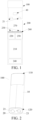
FIG. 1 is a schematic diagram of an electronic atomization device according to an embodiment; -
FIG. 2 is a schematic diagram of an embodiment of an atomizer inFIG. 1 ; -
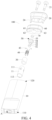
FIG. 3 is a schematic exploded view of the atomizer inFIG. 2 from an angle; -
FIG. 4 is a schematic exploded view of the atomizer inFIG. 2 from another angle; -
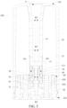
FIG. 5 is a schematic cross-sectional view of the atomizer inFIG. 2 from an angle; -
FIG. 6 is a schematic exploded view of a heating element and a holder inFIG. 3 before assembly from another angle; -
FIG. 7 is a schematic diagram of the heating element and the holder inFIG. 6 after assembly; -
FIG. 8 is a schematic diagram of the heating element inFIG. 7 wrapped with a liquid guide element; -
FIG. 9 is a schematic diagram of a lead fastener assembled in the holder inFIG. 8 ; -
FIG. 10 is a schematic diagram of the liquid guide element inFIG. 9 further sleeved with a tubular element; -
FIG. 11 is a schematic exploded view of a heating element and a holder before assembly according to another embodiment; -
FIG. 12 is a schematic diagram of the heating element and the holder inFIG. 11 after assembly; -
FIG. 13 is a schematic exploded view of a heating element, a holder, and a fastening base before assembly according to another embodiment; -
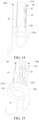
FIG. 14 is a schematic diagram of the heating element and the holder inFIG. 13 after assembly; -
FIG. 15 is a schematic diagram of the holder further assembled with a fastening base inFIG. 14 ; -
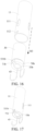
FIG. 16 is a schematic diagram of the heating element further wrapped a liquid guide element and sleeved with a tubular element inFIG. 15 ; -
FIG. 17 is a schematic diagram of the tubular element inFIG. 16 after assembly; -
FIG. 18 is a schematic diagram of an end cap inFIG. 3 from another angle; and -
FIG. 19 is a schematic diagram of an air channel defined between the end cap and a sealing base inFIG. 18 . - For ease of understanding of this application, this application is described in further detail below with reference to the accompanying drawings and specific embodiments.
- An embodiment of this application provides an electronic atomization device. Referring to
FIG. 1 , the electronic atomization device includes anatomizer 100 for storing a liquid substrate and atomizing the liquid substrate to generate an aerosol, and apower supply mechanism 200 for supplying power to theatomizer 100. - In an optional embodiment, as shown in
FIG. 1 , thepower supply mechanism 200 includes: a receivingcavity 270, arranged on an end along a length direction and configured to receive and accommodate at least a part of theatomizer 100; and a firstelectrical contact 230, at least partially exposed in the receivingcavity 270, configured to be electrically connected to theatomizer 100 to supply power to theatomizer 100 when at least a part of theatomizer 100 is received and accommodated in thepower supply mechanism 200. - According to a preferred embodiment shown in
FIG. 1 , a secondelectrical contact 21 is arranged on an end portion of theatomizer 100 opposite to thepower supply mechanism 200 along the length direction, so that when at least a part of theatomizer 100 is received in the receivingcavity 270, the secondelectrical contact 21 is in contact with and abuts against the firstelectrical contact 230 to conduct electricity. - A
seal element 260 is arranged in thepower supply mechanism 200, and at least a part of an internal space of thepower supply mechanism 200 is separated through theseal element 260 to form the receivingcavity 270. In the preferred embodiment shown inFIG. 1 , the sealingmember 260 is constructed to extend along a longitudinal direction perpendicular to thepower supply mechanism 200, and is preferably made by a flexible material such as silica gel, to prevent the liquid substrate seeping from theatomizer 100 to the receivingcavity 270 from flowing to acontroller 220, asensor 250, and other components inside thepower supply mechanism 200. - In the preferred embodiment shown in
FIG. 1 , thepower supply mechanism 200 further includes: abattery cell 210, located at another end facing away from the receivingcavity 270 along a length direction, and configured to supply power; and acontroller 220, arranged between thebattery cell 210 and the receivingcavity 270, and thecontroller 220 operably guides a current between thebattery cell 210 and the firstelectrical contact 230. - During use, the
power supply mechanism 200 includes asensor 250, configured to sense an inhalation flow generated by theatomizer 100 during inhalation, so that thecontroller 220 controls thebattery cell 210, based on a detection signal of thesensor 250, to supply power to theatomizer 100. - Further, in the preferred embodiment shown in
FIG. 1 , a charginginterface 240 is arranged on another end of thepower supply mechanism 200 facing away from the receivingcavity 270, and is configured to supply power to thebattery cell 210. - The embodiments in
FIG. 2 to FIG. 5 are schematic structural diagrams of theatomizer 100 inFIG. 1 according to an embodiment. Theatomizer 100 includes:
amain housing 10. As shown inFIG. 2 to FIG. 3 , themain housing 10 is substantially in a flat cylindrical shape. Themain housing 10 has aproximal end 110 and adistal end 120 opposite to each other along a length direction. According to a common use requirement, theproximal end 110 is configured as an end for a user to inhale an aerosol. Theproximal end 110 is provided with an inhalation port A for the user to inhale. Thedistal end 120 is used as an end combined with thepower supply mechanism 200. Thedistal end 120 of themain housing 10 is an open end on which adetachable end cap 20 is mounted. The open end structure is configured to mount necessary functional components inside themain housing 10. - Further, in the specific embodiments shown in
FIG. 2 to FIG. 5 , the secondelectrical contact 21 penetrates into theatomizer 100 from a surface of theend cap 20, to at least partially exposed on theend cap 20/atomizer 100/distal end 120. When theatomizer 100 is received in the receivingcavity 270 of thepower supply mechanism 200, the secondelectrical contact 21 may be in contact with the firstelectrical contact 230 to conduct electricity. In addition, theend cap 20 is further provided with afirst air inlet 23 for external air to enter into theatomizer 100 during inhalation. - Further, referring to
FIG. 3 to FIG. 5 , the interior of themain housing 10 is provided with aliquid storage cavity 12 configured to store the liquid substrate and an atomization assembly configured to absorb the liquid substrate from theliquid storage cavity 12 and heat and atomize the liquid substrate. The atomization assembly generally includes a capillaryliquid guide element 30 configured to absorb the liquid substrate and aheating element 40 combined on theliquid guide element 30. Theheating element 40 heats at least a part of the liquid substrate of theliquid guide element 30 during energization, to generate the aerosol. In an optional embodiment, theliquid guide element 30 includes flexible fibers, such as cotton fibers, non-woven fabrics, or fiberglass cords, or includes porous materials with a microporous structure, for example, porous ceramics. Theheating element 40 may be combined on theliquid guide element 30 by printing, deposition, sintering, or physical assembly, or wound around theliquid guide element 30. - Further, in the specific embodiments shown in
FIG. 3 to FIG. 5 , the interior of themain housing 10 is provided with anair tube 13 extending from theproximal end 110 toward thedistal end 120 and atubular element 11 extending along the longitudinal direction, spaced apart from theair tube 13, and connected to theair tube 13. After assembly, theair tube 13 and thetubular element 11 jointly define an output channel for outputting the aerosol. - In the specific embodiment shown in
FIG. 5 , thetubular element 11 is an independent component, and is preferably made of a thin rigid material, such as ceramic or stainless steel. Theair tube 13 is integrally molded with themain housing 10 by using a moldable material. - After assembly, the
liquid storage cavity 12 configured to store the liquid substrate is defined between an outer surface of theair tube 13, an outer surface of thetubular element 11, and an inner wall of themain housing 10, that is, thetubular element 11 at least partially defines theliquid storage cavity 12. - In the embodiments shown in
FIG. 3 to FIG. 5 , theliquid storage cavity 12 defined in themain housing 10 is closed by themain housing 10 at theproximal end 110. An end portion of theliquid storage cavity 12 toward thedistal end 120 is open. Further, as shown inFIG. 3 to FIG. 5 , theatomizer 100 further includes:
aflexible sealing base 60, configured to close the open end of theliquid storage cavity 12 toward thedistal end 120, and configured to provide sealing between theend cap 20 and themain housing 10, to prevent the liquid substrate from seeping out. In a specific structure, referring toFIG. 3 to FIG. 5 , theflexible sealing base 60 includes:
aperipheral side wall 610 and a sealingpart 620 located in theperipheral side wall 610. There is aspacing space 630 between the sealingpart 620 and theperipheral side wall 620. Thespacing space 630 is open toward a side facing theend cap 20. During assembly, theend cap 20 is inserted into or extends into thespacing space 630 for assembly. After assembly, theperipheral side wall 610 partially surrounds or encloses theend cap 20, and is supported by theend cap 20 from the inside, to provide sealing between theend cap 20 and themain housing 10. After assembly, the sealingpart 620 extends into or is accommodated in theend cap 20. - The sealing
base 60 is provided with acontact hole 62 penetrating into the sealing base along an axial direction or a longitudinal direction. After assembly, the secondelectrical contact 21 penetrates into or extends into thecontact hole 62. As shown inFIG. 5 , after assembly, the secondelectrical contact 21 extends to theliquid storage cavity 12 after penetrating into thecontact hole 62. Preferably, the secondelectrical contact 21 is flush with a surface of the sealingbase 60. The secondelectrical contact 21 does not protrude or recess relative to the surface of the sealingbase 60. - Further, referring to
FIG. 3 to FIG. 5 , thetubular element 11 is assembled with an atomization assembly, and thetubular element 11 is provided with several liquid guide holes 111 spaced apart along the circumferential direction, for theliquid storage cavity 12 to enter. Therefore, the atomization assembly is in fluid communication with theliquid storage cavity 12 through theliquid guide hole 111 to receive the liquid substrate. - Further, referring to
FIG. 3 to FIG. 5 , the atomization assembly includes:
theliquid guide element 30, flexible in the embodiments, for example, made of flexible fibers such as cotton fibers, non-woven fabrics, or sponges. Theliquid guide element 30 is constructed in an annular shape arranged along the longitudinal direction of themain housing 10. Theliquid guide element 30 is coaxial with thetubular element 11 and located in thetubular element 11. - During embodiment, an outer surface of the
liquid guide element 30 along a radial direction blocks or communicates with theliquid guide hole 111, so that the outer surface of theliquid guide element 30 is configured as a liquid absorbing surface, to receive and absorb the liquid substrate in theliquid storage cavity 12 through theliquid guide hole 111. An inner surface of theliquid guide element 30 along the radial direction is configured as an atomization surface, and the atomization surface is combined with/attached to/abuts against theheating element 40, so that after being transferred to the atomization surface, the liquid substrate is heated and atomized by theheating element 40 to generate and release the aerosol. Theliquid guide element 30 extends along the axial direction of theheating element 40 and surrounds theheating element 40, and is configured to conduct the liquid substrate in theliquid storage cavity 12 to theheating element 40. - Further, referring to
FIG. 3 to FIG. 6 , in the embodiments, theheating element 40 is constructed to extend along the longitudinal direction of themain housing 10/liquid guide element 30. Theheating element 40 is arranged co-axially with theliquid guide element 30. In some optional embodiments, theheating element 40 is a resistive heating mesh, a resistive heating coil, or the like. In the embodiments, theheating element 40 is a heating element wound by a sheet-shaped or mesh-shaped substrate, that is, theheating element 40 is wound by a sheet material. Thewound heating element 40 is in a non-closed tubular shape along the circumferential direction, and is in a cylindrical shape with aside opening 45 along the longitudinal direction. Theheating element 40 includeselectrode parts 41 located at two sides of theside opening 45, a mesh-shapedresistive heating part 42 extending between theelectrode parts 41, and conductive leads 43 connected to theelectrode parts 41. It is cleared that, there are twoelectrode parts 41 and twoconductive leads 43, one being used as a positive end and the other being used as a negative end. - The
resistive heating part 42 is in a mesh shape with mesh holes. Theelectrode parts 41 have no mesh holes. - Further, referring to
FIG. 3 to FIG. 7 , theheating element 40 is wound or fixed on theholder 50. Correspondingly, the sealingbase 60 is further provided with aholder hole 61 penetrating into the sealingbase 60 along the longitudinal direction. Theholder 50 is accommodated or mounted in theholder hole 61. It is cleared that, in a conventional embodiment, an inner diameter of theholder hole 61 is non-constant. Specifically, an inner diameter of theholder hole 61 close to thedistal end 120 is less than an inner diameter away from thedistal end 120. Therefore, there is an abutting step in theholder hole 61. After assembly, theholder 50 extends into theholder hole 61 from a side close to theliquid storage cavity 12 and then abuts against the step to form stop. - Further, as shown in
FIG. 3 to FIG. 10 , a shape or a structure of theholder 50 includes:
asupport part 51, asupport part 52, asupport part 53, asupport part 54, and asupport part 55 arranged along the axial direction sequentially. Thesupport part 51, thesupport part 53, thesupport part 54, and thesupport part 55 are all constructed in annular shapes, and are co-axially arranged. Thesupport part 51 and thesupport part 53 have a same outer diameter and/or inner diameter. An outer diameter of thesupport part 54 is greater than an outer diameter of thesupport part 53, and an outer diameter of thesupport part 55 is greater than the outer diameter of thesupport part 54. - Because the outer diameter of the
support part 54 is greater than the outer diameter of thesupport part 53, after assembly, an end surface of theheating element 40 abuts against an end surface of thesupport part 54. Thesupport part 54 provides stop for theheating element 40. Thesupport part 51, thesupport part 52, and thesupport part 53 may be first parts, and thesupport part 54 and thesupport part 55 may be second parts. It may be understood that, theholder 50 includes a first part surrounded by theheating element 40 and a second part exposed outside theheating element 40. The first part is configured to provide support for theheating element 40 from the inside of theheating element 40, and the second part abuts against theheating element 40 to provide stop. - Because the
heating element 40 surrounds the first part, the heating element is made of a sheet material wound around the first part of theholder 50, that is, theheating element 40 is made of the sheet material wound around at least a part of theholder 50. - The
support part 52 is an elongated shape extending along an axial direction of theholder 50, rather than an annular shape, and is further configured to connect thesupport part 51 to thesupport part 53 in addition to providing support. - In some embodiments, the
holder 50 is made of an electrically insulating rigid material, for example, ceramic, PEEK, polytetrafluoroethylene, or a surface-insulated metal or alloy. - Further, referring to
FIG. 6 , theresistive heating part 42 of theheating element 40 includes aheating portion 421 located at a central part along the axial direction. Theheating portion 421 mainly generates Joule heat when a direct current flows through theheating portion 421. The direct current substantially mainly flows through theheating portion 421. Theheating portion 421 is constructed in a mesh shape with mesh holes. - The
resistive heating part 42 further includes a first tooth portion orwing portion 422 extending from theheating portion 421 toward an upper end along the axial direction. Theresistive heating part 42 further includes a second tooth portion orwing portion 423 extending from theheating portion 421 toward a lower end along the axial direction. The upper end and the lower end are a first end and a second end of theheating element 40 respectively. The first tooth portion orwing portion 422 terminates at the upper end of theheating element 40, and a plurality of first tooth portions or wing portions are provided and discrete from each other. The second tooth portion orwing portion 423 terminates at the lower end of theheating element 40, and a plurality of second tooth portions or wing portions are provided and discrete from each other. During power supply, a current flows less through the first tooth portion orwing portion 422 and the second tooth portion orwing portion 423, and the first tooth portion orwing portion 422 and the second tooth portion orwing portion 423 are substantially less Joule heated, so that a heating region of theresistive heating part 42 is mainly located at theheating portion 421. - Correspondingly, during assembly, the first tooth portion or
wing portion 422 surrounds and is combined on thesupport part 51 of theholder 50, and the second tooth portion orwing portion 423 surrounds and is combined on thesupport part 53 of theholder 50. After assembly, the first tooth portion orwing portion 422 is configured as a first joint portion combined on theholder 50, and the second tooth portion orwing portion 423 is configured as a second joint portion combined on theholder 50. It may be understood that, the first joint portion and the second joint portion are located at the first end and the second end of theheating element 40 respectively. After assembly, thesupport part 51 and thesupport part 53 of theholder 50 are supported from the inside at two ends of theheating element 40 respectively, and themain heating portion 421 of theheating element 40 is exposed in the air channel. In other words, theholder 50 is at least partially surrounded by theheating element 40 to be positioned inside theheating element 40, and is configured to at least partially provide support for theheating element 40 from the inside of theheating element 40. After assembly, theholder 50 substantially avoids themain heating portion 421, which is beneficial to preventing a large amount of heat of theheating element 40 from being transferred to theholder 50. - Alternatively, in some other variant embodiments, the
heating element 40 is in a tubular shape, includes an annular first joint portion at the upper end along the axial direction, and is configured to surround and be combined on thesupport part 51 of theholder 50. The lower end of theheating element 40 along the axial direction includes an annular second joint portion, and is configured to surround and be combined on thesupport part 53 of theholder 50. Theheating element 40 further includes a heating portion extending between the first joint portion and the second joint portion. The heating portion is mainly configured to perform resistive heating. Thesupport part 51 is a first support part, and thesupport part 53 is a second support part. In the foregoing content, thesupport part 51 and thesupport part 53 are both annular. The first joint portion is configured to surround and be combined on thesupport part 51, the second joint portion is configured to surround and be combined on thesupport part 53, and theheating element 40 further includes a heating portion extending between the first joint portion and the second joint portion. Therefore, it may be understood that, the first support part is arranged to provide support for theheating element 40 from the inside at a first end close to theheating element 40, and the second support part is arranged to provide support for the heating element from the inside at a second end close to theheating element 40. Similarly, the heating portion may be in a spiral wire structure or in a mesh shape. After assembly, theholder 50 avoids the heating portion, and the heating portion is exposed in a hollow of theholder 50, so that the heating portion is exposed in the airflow channel. - A process of supporting and assembling the
heating element 40, theliquid guide element 30, and thetubular element 11 in theholder 50 includes the following steps. - S10: An unwound/flat unwound
heating element 40 is wound around thesupport part 51, thesupport part 52, and thesupport part 53, as shown inFIG. 7 . It is cleared that, after winding, an extension length of theheating element 40 extends from thesupport part 51 to thesupport part 53. After winding, thesupport part 51 provides support for theheating element 40 from the inside at the upper end of theheating element 40. Thesupport part 53 provides support for theheating element 40 from the inside at the lower end of theheating element 40. After winding, theelectrode parts 41 of theheating element 40 abut against thesupport part 42. After winding, thesupport part 42 extends into theside opening 45 between theelectrode parts 41. Thesupport part 42 is a third support part. The third support part is at least partially located in the side opening of theheating element 40 to provide support for theheating element 40. After assembly, the lower end of theheating element 40 abuts against the support part 44. - Referring to
FIG. 7 and FIG. 6 , a surface of thesupport part 51 is provided with alead groove 56, and a surface of thesupport part 53 is provided with alead groove 57. Thelead groove 56 and thelead groove 57 extend along the axial direction of theholder 50 and are close to thesupport part 52. Theholder 50 is further provided with alead hole 58 penetrating into thesupport part 54 and thesupport part 55. After assembly, the conductive leads 43 of theheating element 40 are retained in thelead groove 56 and thelead groove 57, and extend to the outside of thesupport part 55 after penetrating into thelead hole 58. - S20: The
liquid guide element 30 is further wrapped, wound, or sleeved outside theheating element 60 inFIG. 7 , as shown inFIG. 8 . Theliquid guide element 30 may be wound by a closed annular flexible fiber, or by a flexible fiber strip. A lower end of theliquid guide element 30 abuts against the support part 44. - S30: A
lead fastener 70 is further mounted on a lower end of theholder 50 inFIG. 8 , to fasten or abut the conductive leads 43 against an inner wall of thesupport part 45, to prevent the conductive leads 43 from bending, entangling, or contacting to cause a short circuit or the like. As shown inFIG. 9 , thelead hole 58 is at least partially formed on an inner surface of thesupport part 55. - S40: The
tubular element 11 is further sleeved outside theliquid guide element 30 inFIG. 9 , to form an assembled state inFIG. 10 . As shown inFIG. 10 , a lower end of thetubular element 11 surrounds and is sleeved on thesupport part 54, and abuts against thesupport part 55 to form support and stop, that is, thetubular element 11 abuts against theholder 50 to be stopped. In addition, theholder 50 is further provided with apositioning protrusion 541, which may also be referred to as a positioning clamping protrusion, extending from thesupport part 55 toward thesupport part 54. The lower end of thetubular element 11 is provided with apositioning notch 112, which may also be referred to as a first notch, groove, or hole. During assembly, thepositioning protrusion 541 cooperates with thepositioning notch 112, to provide positioning. After assembly, thepositioning protrusion 541 and thepositioning notch 112 cooperate to prevent rotation of thetubular element 11 relative to theholder 50. In other words, theholder 50 is provided with the positioning clamping protrusion extending into the first notch, groove, or hole, to prevent thetubular element 11 from rotating relative to theholder 50. - Alternatively, in some other variant embodiments, the
positioning notch 112 may be a positioning groove, a positioning hole, or the like that provides positioning and prevents rotation. - Further referring to
FIG. 10 , in an assembled module, theliquid guide hole 111 of thetubular element 11 is opposite to theresistive heating part 42 of theheating element 40 along the radial direction. The support strength of theresistive heating part 42 of theheating element 40 is stronger at the part of theliquid guide element 30 opposite to theliquid guide hole 111, to better control liquid transfer. - Further, in
FIG. 10 , thetubular element 11, the atomization assembly, theholder 50, and thelead fastener 70 are assembled into a module, which is beneficial for modular production and assembly of theatomizer 100. Then, the assembled module inFIG. 10 extends into theholder hole 61 of the sealingbase 60 to be fixed. Further, after the module inFIG. 10 is assembled with the sealingbase 60, the conductive leads 43 pass through theholder hole 61 to the outside of the sealingbase 60, and are bent into thecontact hole 62 to contact with the secondelectrical contact 21 or welded to conduct electricity. - Further, according to a preferred embodiment shown in
FIG. 10 , theliquid guide element 30 made of flexible fibers or sponges is squeezed or compressed by thetubular element 11 and theheating element 40/holder 50 from the inside and the outside, so that theliquid guide element 30 is stably limited and retained between thetubular element 11 and theheating element 40/holder 50. In other words, theliquid guide element 30 is radially squeezed or compressed between thetubular element 11 and theheating element 40. Theliquid guide element 30 may be entirely squeezed or compressed, or may be partially squeezed or compressed as long as theliquid guide element 30 is stably limited and retained between thetubular element 11 and theheating element 40/holder 50. In addition, because thetubular element 11 squeezes theliquid guide element 30 inward, it can be learned that, thetubular element 11 is constructed to surround and retain theliquid guide element 30. - Further, referring to
FIG. 4 andFIG. 5 , after assembly, the lower end of thetubular element 11 is at least partially inserted into theholder hole 61 with theholder 50. An upper end of thetubular element 11 is further provided with apositioning notch 113, for theair tube 13 to be inserted from the upper end of thetubular element 11 and cooperate with thepositioning notch 113 to implement positioning. In a preferred embodiment, theair tube 13 is inserted into thetubular element 11 by riveting, tight fitting, or the like, so that theair tube 13 and thetubular element 11 are tightly combined and sealed. This is beneficial to preventing the liquid substrate from seeping between the air tube and the tubular element. - During inhalation after assembly, referring to an arrow R2 in
FIG. 5 , air entering through theair inlet 23 of theend cap 20 enters the hollow of theholder 50 through theholder hole 61 of the sealingbase 60, passes through theholder 50, and then carries the aerosol released by the atomization surface, and is outputted from thetubular element 11 and the air tube to the inhalation port A to be inhaled. The hollow is the airflow channel. During inhalation, the airflow path or the airflow channel passes through theholder 50. It is cleared that, the airflow path or the airflow channel also passes through the tubular, annular, or wound cylindricalliquid guide element 30. The airflow path or the airflow channel passes through the tubular, annular, or woundcylindrical heating element 40. In other words, theair inlet 23, the inhalation port A, and the airflow channel are arranged to define the airflow path from theair inlet 23 to the inhalation port A through theheating element 40. - Further,
FIG. 11 is a schematic diagram of aholder 50a for support and assembly according to another embodiment. In the variable embodiments, a structure of theholder 50a includes:
asupport part 51a, asupport part 52a, asupport part 53a, and asupport part 54a sequentially arranged along the axial direction. Thesupport part 51a, thesupport part 53a, and thesupport part 54a are all constructed in annular shapes, and are co-axially arranged. An outer diameter of thesupport part 51a is the same as an outer diameter of thesupport part 53a. An outer diameter of thesupport part 54a is greater than the outer diameter thesupport part 53a. Thesupport part 52a is in an elongated shape extending between thesupport part 51a and thesupport part 53a. - During assembly, the
heating element 40 is combined on thesupport part 51a, thesupport part 52a, and thesupport part 53a by sleeving, winding, coiling, or wrapping. A state after winding is shown inFIG. 12 . Thesupport part 51a provides support for theheating element 40 from the inside at the upper end of theheating element 40. Thesupport part 53a provides support for theheating element 40 from the inside at the lower end of theheating element 40. Thesupport part 52a is used for theelectrode parts 41 and the conductive leads 43 of theheating element 40 to abut against and be fixed. - A surface of the
support part 51a is further provided with alead groove 56a. A surface of thesupport part 53a is further provided with alead groove 57a. A surface of thesupport part 54a is further provided with alead groove 58a. After assembly, the conductive leads 43 are sequentially accommodated in and pass through thelead groove 56a, thelead groove 57a, and thelead groove 58a to be fixed. - Similarly, in
FIG. 12 , after theheating element 40 is assembled to theholder 50a, theliquid guide element 30 and thetubular element 11 may be further wrapped, sleeved, or wound, and then assembled into a module. Theliquid guide element 30 surrounds and is wrapped around theheating element 40, and abuts against thesupport part 54a. Similarly, the surface of thesupport part 54a is provided with apositioning protrusion 541a, for the lower end of thetubular element 11 to abut against and be positioned during assembly. - Further,
FIG. 13 is a schematic diagram of aholder 50b and alead fastener 70b according to another embodiment. In the various embodiments, theholder 50b includes:
asupport part 51b, asupport part 52b, and asupport part 53b sequentially arranged along the axial direction. Thesupport part 51b and thesupport part 53b are co-axially positioned and in annular shapes with same outer diameters. Thesupport part 52b is in an elongated shape extending between thesupport part 51b and thesupport part 53b. - During assembly, the
heating element 40 is directly wrapped, wound, or sleeved on theholder 50a. Specifically, after assembly, referring toFIG. 14 , thesupport part 51b provides support from the inside at the upper end of theheating element 40. Thesupport part 53b provides support from the inside at the lower end of theheating element 40. Theelectrode parts 41 and the conductive leads 43 of theheating element 40 abut against thesupport part 52b. - A surface of the
holder 50b is provided with alead groove 56a extending from the upper end to the lower end, to accommodate and assemble the conductive leads 43. - Further, as shown in
FIG. 13 andFIG. 15 , thelead fastener 70b is in an annular shape, and an inner diameter of the lead fastener is greater than an outer diameter of thesupport part 53b, so that thelead fastener 70b can surround or be sleeved outside thesupport part 53b. A surface of thesupport part 53b is provided with apositioning protrusion 53 1b extending outward along a radial direction. Thelead fastener 70b is provided with apositioning notch 71b. After assembly, thepositioning protrusion 531b extends from the inside of thepositioning notch 71b to the outside of thepositioning notch 71b along the radial direction, as shown inFIG. 15 . After assembly, thelead fastener 70b restricts and fixes the conductive leads 43 accommodated and retained in thelead groove 56a on the surface of theholder 50b from the outside, to prevent the conductive leads 43 from falling out of thelead groove 56a. - After the assembly in
FIG. 15 , inFIG. 16 and FIG. 17 , theheating element 40 is further sleeved, wrapped, or wound with theliquid guide element 30, and sleeved with thetubular element 11. During assembly, thepositioning notch 112 at the lower end of thetubular element 11 cooperates with a part of thepositioning protrusion 531b of thesupport part 53b extending out of thelead fastener 70b to abut against and be positioned. After assembly, a module shown inFIG. 17 is formed, and then the entire module is inserted into theholder hole 61 of the sealingbase 60 to complete assembly with the sealingbase 60. - Further, in another preferred embodiment, referring to
FIG. 18 and FIG. 19 , theend cap 20 is provided with anextension arm 24 extending along the longitudinal direction. Theextension arm 24 protrudes relative to another part of theend cap 20. Theextension arm 24 is substantially in an elongated cylindrical shape. Theextension arm 24 has a length of approximately 3 mm to 8 mm and an outer diameter of approximately 1 mm to 3 mm. A surface of theextension arm 24 is provided with anair groove 241 extending along the axial direction. Theair groove 241 has a width of approximately 0.3 mm to 1 mm and a depth of approximately 0.2 mm to 0.5 mm. - Correspondingly, the sealing
base 60 is provided with a throughhole 63 penetrating into or extending to an upper end surface. The upper end surface is a first surface for sealing or covering the open end of theliquid storage cavity 12. After assembly, theextension arm 24 is inserted into or extends into the throughhole 63, and is defined between theair groove 241 and an inner surface of the throughhole 63 to form the air channel for external air to enter theliquid storage cavity 12. Therefore, when a negative pressure in theliquid storage cavity 12 exceeds a threshold, external air entering through anair inlet hole 23 can enter into theliquid storage cavity 12 along the air channel defined by theair groove 241 as shown by an arrow R4 inFIG. 19 , to relieve the negative pressure in theliquid storage cavity 12. - In some other variant embodiments, the
air groove 241 is formed on an inner wall surface of the throughhole 63. Correspondingly, the air channel is defined between theair groove 241 on the inner wall surface of the throughhole 63 and theextension arm 24. - It should be noted that, the specification of this application and the accompanying drawings thereof illustrate preferred embodiments of this application, but this application is not limited to the embodiments described in the specification. Further, a person of ordinary skill in the art may make improvements or variations according to the foregoing descriptions, and such improvements and variations shall all fall within the protection scope of the appended claims of this application.
Claims (21)
- An atomizer, comprising:a liquid storage cavity, configured to store a liquid substrate;a heating element, constructed in a cylindrical shape extending along a longitudinal direction of the atomizer, to heat the liquid substrate to generate an aerosol; anda holder, at least partially surrounded by the heating element to be positioned inside the heating element, and configured to at least partially support the heating element from within the heating element.
- The atomizer according to claim 1, wherein the heating element is made of a material sheet wound around at least a part of the holder.
- The atomizer according to claim 1 or 2, further comprising:an inhalation port; andan air inlet and an airflow channel located between the air inlet and the inhalation port, wherein the air inlet, the inhalation port, and the airflow channel are arranged to define an airflow path from the air inlet to the inhalation port through the heating element, to transfer the aerosol to the inhalation port, andthe airflow channel at least partially passes through the holder along the longitudinal direction of the atomizer.
- The atomizer according to claim 1 or 2, wherein the holder comprises a first part surrounded by the heating element and a second part exposed outside the heating element, the first part is configured to provide support for the heating element from the inside of the heating element, and the second part abuts against the heating element to provide stop.
- The atomizer according to claim 1 or 2, further comprising:
a liquid guide element, extending along an axial direction of the heating element and surrounding the heating element, and configured to conduct the liquid substrate in the liquid storage cavity to the heating element. - The atomizer according to claim 5, further comprising:
a tubular element, extending along the longitudinal direction of the atomizer, and at least partially defining the liquid storage cavity, wherein the tubular element is constructed to surround and retain the liquid guide element and abut against the holder to be stopped. - The atomizer according to claim 6, wherein the liquid guide element is flexible, and is at least partially radially squeezed or compressed between the tubular element and the heating element.
- The atomizer according to claim 6, wherein:the tubular element is provided with a first notch, groove, or hole; andthe holder is provided with a positioning clamping protrusion extending into the first notch, groove, or hole, to prevent the tubular element from rotating relative to the holder.
- The atomizer according to claim 1 or 2, wherein:the heating element comprises a first end and a second end facing away from each other along an axial direction; andthe holder comprises a first support part and a second support part spaced apart along a longitudinal direction, wherein:the first support part is in an annular shape and is arranged to provide support for the heating element from the inside at a location close to the first end of the heating element; andthe second support part is in an annular shape and is arranged to provide support for the heating element from the inside at a location close to the second end of the heating element.
- The atomizer according to claim 1 or 2, wherein the heating element defines a side opening extending along an axial direction, to enable the heating element to be non-closed along a circumferential direction.
- The atomizer according to claim 10, wherein the holder further comprises a third support part extending along the longitudinal direction, and the third support part is at least partially located in the side opening of the heating element, to provide support for the heating element.
- The atomizer according to claim 1 or 2, wherein:the heating element comprises a conductive lead for supplying power to the heating element; andan inner surface or an outer surface of the holder is provided with a lead groove, and the conductive lead is at least partially accommodated and retained in the lead groove.
- The atomizer according to claim 12, further comprising:
a lead fastener, at least a part of the lead fastener shielding or covering the conductive lead accommodated in the lead groove, to prevent the conductive lead from leaving the lead groove. - The atomizer according to claim 13, wherein the lead fastener is substantially constructed in an annular shape.
- The atomizer according to claim 1 or 2, wherein the liquid storage cavity is provided with an open end, and the atomizer further comprises:
a flexible sealing base, configured to cover the open end to seal the liquid storage cavity, wherein the sealing base accommodates and retains at least a part of the holder. - The atomizer according to claim 15, further comprising:
an end support member, configured to support the sealing base, wherein:the sealing base comprises a first surface for sealing or covering the open end, and the sealing base is further provided with a through hole extending to the first surface; andthe end support member is provided with an extension arm at least partially extending in the through hole, and an air channel is defined between the extension arm and the through hole, to provide a path for air to enter the liquid storage cavity. - The atomizer according to claim 16, wherein the air channel comprises an air groove provided on an outer surface of the extension arm and/or an inner surface of the through hole.
- The atomizer according to claim 1 or 2, wherein the heating element comprises a first end and a second end facing away from each other along an axial direction, and the heating element further comprises:a heating portion, configured to generate Joule heat;a first tooth portion or wing portion, extending from the heating portion toward the first end and terminating at the first end; anda second tooth portion or wing portion, extending from the heating portion toward the second end and terminating at the second end, whereinthe holder is arranged to provide support for the first tooth portion or wing portion and/or the second tooth portion or wing portion and avoid the heating portion.
- The atomizer according to claim 3, wherein the heating element comprises a first end and a second end facing away from each other along an axial direction, and the heating element further comprises:a first joint portion combined on the holder, and located at the first end;a second joint portion combined on the holder, and located at the second end; anda heating portion, located between the first j oint portion and the second j oint portion along an axial direction, and configured to generate Joule heat, wherein the heating portion avoids the holder, and is exposed in the airflow channel.
- An atomizer, comprising:a tubular element, constructed to extend along a longitudinal direction of the atomizer;a liquid storage cavity, at least partially defined by the tubular element, and configured to store a liquid substrate, wherein the liquid storage cavity is provided with an open end;a heating element, located in the tubular element, and configured to heat the liquid substrate to generate an aerosol;a flexible sealing base, configured to cover the open end to seal the liquid storage cavity, wherein the sealing base accommodates and surrounds at least a part of the tubular element; andan end support member, configured to support the sealing base, wherein the sealing base comprises a first surface for sealing or covering the open end, and the sealing base is further provided with a through hole extending to the first surface,wherein the end support member is provided with an extension arm at least partially extending in the through hole, and an air channel is defined between the extension arm and the through hole, to provide a path for air to enter the liquid storage cavity.
- An electronic atomization device, comprising an atomizer configured to atomize a liquid substrate to generate an aerosol, and a power supply device configured to supply power to the atomizer, wherein the atomizer comprises the atomizer according to any one of claims 1 to 20.
Applications Claiming Priority (2)
| Application Number | Priority Date | Filing Date | Title |
|---|---|---|---|
| CN202210357372.4A CN116919006A (en) | 2022-04-02 | 2022-04-02 | Atomizer and electronic atomization device |
| PCT/CN2023/085541 WO2023186114A1 (en) | 2022-04-02 | 2023-03-31 | Atomizer and electronic atomization device |
Publications (2)
| Publication Number | Publication Date |
|---|---|
| EP4487703A1 true EP4487703A1 (en) | 2025-01-08 |
| EP4487703A4 EP4487703A4 (en) | 2025-08-27 |
Family
ID=88199496
Family Applications (1)
| Application Number | Title | Priority Date | Filing Date |
|---|---|---|---|
| EP23778478.0A Pending EP4487703A4 (en) | 2022-04-02 | 2023-03-31 | Atomizer and electronic atomization device |
Country Status (4)
| Country | Link |
|---|---|
| US (1) | US20250212957A1 (en) |
| EP (1) | EP4487703A4 (en) |
| CN (1) | CN116919006A (en) |
| WO (1) | WO2023186114A1 (en) |
Families Citing this family (1)
| Publication number | Priority date | Publication date | Assignee | Title |
|---|---|---|---|---|
| CN221449914U (en) * | 2023-12-21 | 2024-08-02 | 深圳市合元科技有限公司 | Atomizer and electronic atomization device |
Family Cites Families (12)
| Publication number | Priority date | Publication date | Assignee | Title |
|---|---|---|---|---|
| CN204273230U (en) * | 2014-04-24 | 2015-04-22 | 惠州市吉瑞科技有限公司 | A kind of atomizer and electronic cigarette |
| CN104522891A (en) * | 2014-12-19 | 2015-04-22 | 深圳市麦克韦尔科技有限公司 | Electronic cigarette and atomization device thereof |
| US10251424B2 (en) * | 2016-03-22 | 2019-04-09 | Altria Client Services Llc | Electronic vaping device |
| WO2019134883A2 (en) * | 2018-01-05 | 2019-07-11 | Philip Morris Products S.A. | Cartridge and e-vaping device |
| EP4111893B1 (en) * | 2020-11-20 | 2023-10-04 | Shenzhen Huachengda Precision Industry Co.Ltd. | Atomizing unit and atomizing device |
| CN215958315U (en) * | 2021-07-21 | 2022-03-08 | 深圳市合元科技有限公司 | Atomizer, electronic atomization device and sealing element for atomizer |
| CN215347028U (en) * | 2021-04-16 | 2021-12-31 | 深圳市合元科技有限公司 | Atomizer and aerosol-generating device |
| CN215936292U (en) * | 2021-06-24 | 2022-03-04 | 常州市派腾电子技术服务有限公司 | Atomizer and aerosol generating device |
| CN113712268B (en) * | 2021-08-18 | 2025-01-10 | 深圳市华诚达精密工业有限公司 | Heating atomizing core, heating atomizing mechanism, heating atomizer and electronic atomizing device thereof |
| CN215736911U (en) * | 2021-09-07 | 2022-02-08 | 东莞市亿海电子有限公司 | Atomizers and Electronic Atomizers |
| CN114158784A (en) * | 2022-01-17 | 2022-03-11 | 深圳市优维尔科技有限公司 | Atomizing core, atomizer and electronic atomization device |
| CN217446658U (en) * | 2022-04-02 | 2022-09-20 | 深圳市合元科技有限公司 | Atomizer and electronic atomization device |
-
2022
- 2022-04-02 CN CN202210357372.4A patent/CN116919006A/en active Pending
-
2023
- 2023-03-31 WO PCT/CN2023/085541 patent/WO2023186114A1/en not_active Ceased
- 2023-03-31 EP EP23778478.0A patent/EP4487703A4/en active Pending
- 2023-03-31 US US18/853,679 patent/US20250212957A1/en active Pending
Also Published As
| Publication number | Publication date |
|---|---|
| CN116919006A (en) | 2023-10-24 |
| EP4487703A4 (en) | 2025-08-27 |
| WO2023186114A1 (en) | 2023-10-05 |
| US20250212957A1 (en) | 2025-07-03 |
Similar Documents
| Publication | Publication Date | Title |
|---|---|---|
| KR20210098498A (en) | Aerosol-generating systems comprising nebulizers and nebulizers | |
| US20240389655A1 (en) | Atomizer and electronic atomization device | |
| CN217446654U (en) | Atomizing assembly and aerosol generating device | |
| KR20230034426A (en) | Aerosol delivery device with a reservoir housing and a vaporizer assembly | |
| EP4316277A1 (en) | Atomizer, electronic atomization device, and sealing element for atomizer | |
| CN217446658U (en) | Atomizer and electronic atomization device | |
| US20250212957A1 (en) | Atomizer and electronic atomization device | |
| CN220712894U (en) | Atomizer and electronic atomization device | |
| CN219613037U (en) | Atomizer, electronic atomization device and atomization assembly | |
| EP4458183A1 (en) | Electronic atomization device and support for electronic atomization device | |
| CN215347024U (en) | Atomizers and Electronic Atomizers | |
| CN215347034U (en) | Atomizer and electronic atomization device | |
| EP4728902A1 (en) | Atomizer and electronic atomization device | |
| CN214431781U (en) | Atomizer and electronic atomization device | |
| CN214103213U (en) | Atomizer and electronic cigarette | |
| CN114098154B (en) | Atomizers and e-cigarettes | |
| WO2023208105A1 (en) | Aerosol product heating assembly and aerosol generation device | |
| CN114847520B (en) | Atomizers and electronic atomization devices | |
| CN117397864A (en) | Heaters, nebulizers and aerosol generating devices | |
| EP4699467A1 (en) | Atomizer and electronic atomization device | |
| CN116784532A (en) | Atomizers and electronic atomization devices | |
| EP4248779A1 (en) | Vaporizer and electronic vaporization device | |
| CN220236066U (en) | Atomizer and atomizing device | |
| CN116406824A (en) | Atomizing core unit, atomizer and aerosol generating device | |
| CN219982149U (en) | Atomizer and electronic atomization device |
Legal Events
| Date | Code | Title | Description |
|---|---|---|---|
| STAA | Information on the status of an ep patent application or granted ep patent |
Free format text: STATUS: THE INTERNATIONAL PUBLICATION HAS BEEN MADE |
|
| PUAI | Public reference made under article 153(3) epc to a published international application that has entered the european phase |
Free format text: ORIGINAL CODE: 0009012 |
|
| STAA | Information on the status of an ep patent application or granted ep patent |
Free format text: STATUS: REQUEST FOR EXAMINATION WAS MADE |
|
| 17P | Request for examination filed |
Effective date: 20240930 |
|
| AK | Designated contracting states |
Kind code of ref document: A1 Designated state(s): AL AT BE BG CH CY CZ DE DK EE ES FI FR GB GR HR HU IE IS IT LI LT LU LV MC ME MK MT NL NO PL PT RO RS SE SI SK SM TR |
|
| REG | Reference to a national code |
Ref country code: DE Ref legal event code: R079 Free format text: PREVIOUS MAIN CLASS: A24F0040100000 Ipc: A24F0040460000 |
|
| RIC1 | Information provided on ipc code assigned before grant |
Ipc: A24F 40/70 20200101ALN20250430BHEP Ipc: A24F 40/485 20200101ALN20250430BHEP Ipc: A24F 40/42 20200101ALN20250430BHEP Ipc: A24F 40/10 20200101ALN20250430BHEP Ipc: A24F 40/46 20200101AFI20250430BHEP |
|
| DAV | Request for validation of the european patent (deleted) | ||
| DAX | Request for extension of the european patent (deleted) | ||
| A4 | Supplementary search report drawn up and despatched |
Effective date: 20250729 |
|
| RIC1 | Information provided on ipc code assigned before grant |
Ipc: A24F 40/46 20200101AFI20250723BHEP Ipc: A24F 40/10 20200101ALN20250723BHEP Ipc: A24F 40/42 20200101ALN20250723BHEP Ipc: A24F 40/485 20200101ALN20250723BHEP Ipc: A24F 40/70 20200101ALN20250723BHEP |