EP4486038A1 - Kommunikationsverfahren und -vorrichtung - Google Patents
Kommunikationsverfahren und -vorrichtung Download PDFInfo
- Publication number
- EP4486038A1 EP4486038A1 EP23777968.1A EP23777968A EP4486038A1 EP 4486038 A1 EP4486038 A1 EP 4486038A1 EP 23777968 A EP23777968 A EP 23777968A EP 4486038 A1 EP4486038 A1 EP 4486038A1
- Authority
- EP
- European Patent Office
- Prior art keywords
- transmission delay
- network element
- delay
- network
- information
- Prior art date
- Legal status (The legal status is an assumption and is not a legal conclusion. Google has not performed a legal analysis and makes no representation as to the accuracy of the status listed.)
- Pending
Links
Images


Classifications
-
- H—ELECTRICITY
- H04—ELECTRIC COMMUNICATION TECHNIQUE
- H04W—WIRELESS COMMUNICATION NETWORKS
- H04W28/00—Network traffic management; Network resource management
- H04W28/02—Traffic management, e.g. flow control or congestion control
- H04W28/0231—Traffic management, e.g. flow control or congestion control based on communication conditions
- H04W28/0236—Traffic management, e.g. flow control or congestion control based on communication conditions radio quality, e.g. interference, losses or delay
-
- H—ELECTRICITY
- H04—ELECTRIC COMMUNICATION TECHNIQUE
- H04L—TRANSMISSION OF DIGITAL INFORMATION, e.g. TELEGRAPHIC COMMUNICATION
- H04L41/00—Arrangements for maintenance, administration or management of data switching networks, e.g. of packet switching networks
- H04L41/08—Configuration management of networks or network elements
- H04L41/0894—Policy-based network configuration management
-
- H—ELECTRICITY
- H04—ELECTRIC COMMUNICATION TECHNIQUE
- H04L—TRANSMISSION OF DIGITAL INFORMATION, e.g. TELEGRAPHIC COMMUNICATION
- H04L47/00—Traffic control in data switching networks
- H04L47/50—Queue scheduling
- H04L47/62—Queue scheduling characterised by scheduling criteria
- H04L47/625—Queue scheduling characterised by scheduling criteria for service slots or service orders
- H04L47/627—Queue scheduling characterised by scheduling criteria for service slots or service orders policing
-
- H—ELECTRICITY
- H04—ELECTRIC COMMUNICATION TECHNIQUE
- H04L—TRANSMISSION OF DIGITAL INFORMATION, e.g. TELEGRAPHIC COMMUNICATION
- H04L41/00—Arrangements for maintenance, administration or management of data switching networks, e.g. of packet switching networks
- H04L41/50—Network service management, e.g. ensuring proper service fulfilment according to agreements
- H04L41/5003—Managing SLA; Interaction between SLA and QoS
- H04L41/5019—Ensuring fulfilment of SLA
-
- H—ELECTRICITY
- H04—ELECTRIC COMMUNICATION TECHNIQUE
- H04L—TRANSMISSION OF DIGITAL INFORMATION, e.g. TELEGRAPHIC COMMUNICATION
- H04L43/00—Arrangements for monitoring or testing data switching networks
- H04L43/08—Monitoring or testing based on specific metrics, e.g. QoS, energy consumption or environmental parameters
- H04L43/0852—Delays
- H04L43/0864—Round trip delays
-
- H—ELECTRICITY
- H04—ELECTRIC COMMUNICATION TECHNIQUE
- H04L—TRANSMISSION OF DIGITAL INFORMATION, e.g. TELEGRAPHIC COMMUNICATION
- H04L47/00—Traffic control in data switching networks
- H04L47/50—Queue scheduling
- H04L47/56—Queue scheduling implementing delay-aware scheduling
-
- H—ELECTRICITY
- H04—ELECTRIC COMMUNICATION TECHNIQUE
- H04W—WIRELESS COMMUNICATION NETWORKS
- H04W28/00—Network traffic management; Network resource management
- H04W28/02—Traffic management, e.g. flow control or congestion control
- H04W28/0205—Traffic management, e.g. flow control or congestion control at the air interface
-
- H—ELECTRICITY
- H04—ELECTRIC COMMUNICATION TECHNIQUE
- H04W—WIRELESS COMMUNICATION NETWORKS
- H04W28/00—Network traffic management; Network resource management
- H04W28/02—Traffic management, e.g. flow control or congestion control
- H04W28/08—Load balancing or load distribution
- H04W28/09—Management thereof
- H04W28/0925—Management thereof using policies
-
- H—ELECTRICITY
- H04—ELECTRIC COMMUNICATION TECHNIQUE
- H04L—TRANSMISSION OF DIGITAL INFORMATION, e.g. TELEGRAPHIC COMMUNICATION
- H04L47/00—Traffic control in data switching networks
- H04L47/10—Flow control; Congestion control
- H04L47/28—Flow control; Congestion control in relation to timing considerations
- H04L47/283—Flow control; Congestion control in relation to timing considerations in response to processing delays, e.g. caused by jitter or round trip time [RTT]
Definitions
- This application relates to the communication field, and in particular, to a communication method and apparatus.
- a terminal collects user-related data, and sends the user-related data to an application server for processing, to obtain processed data from the application server.
- virtual reality virtual reality
- the terminal collects action information of a user, for example, information about a head action, a hand action, a squatting action, a stand-up action, or the like, and sends the information to the application server by using a communication network.
- the application server renders an image based on the action information of the user, and sends a rendered image to the terminal by using the communication network, to provide the rendered image for the user to watch.
- a delay between collecting the user-related data by the terminal and obtaining the processed data by the terminal is large, affecting user experience.
- an air interface delay may be determined based on time and an end-to-end delay.
- the data sent by the terminal carries uplink sending time.
- a downlink delay budget is determined based on the uplink sending time, and an air interface resource of a radio access network element is adjusted based on the downlink delay budget.
- the radio access network element needs to adjust a data processing policy for each downlink data packet, for example, scheduling the air interface resource. Consequently, a data processing process is complex and inefficient.
- Embodiments of this application provide a communication method and apparatus, to reduce complexity of a data processing process. In this way, both data processing efficiency and a data processing delay are ensured.
- a communication method includes: An application server determines a first transmission delay, where the first transmission delay is used to represent a round-trip transmission latency requirement of service data in a network.
- the application server sends the first transmission delay to a policy control network element, where the first transmission delay is used by the policy control network element to determine, based on the first transmission delay, delay budget information for transmitting the service data, and the delay budget information indicates an uplink transmission delay budget and/or a downlink transmission delay budget.
- the policy control network element determines the delay budget information based on the first transmission delay, and sends the delay budget information to a radio access network element by using a session management network element.
- the radio access network element may schedule an air interface resource based on the uplink transmission delay budget and/or the downlink transmission delay budget in the delay budget information.
- the air interface resource may be adjusted when the air interface resource cannot support the current delay budget information, so that scheduling that is of the air interface resource and that is for each data packet can be avoided. In this way, a frequency of adjusting the air interface resource is reduced, data processing complexity is reduced, and both a service delay requirement and data processing efficiency are ensured.
- the method provided in the first aspect may further include: The application server obtains a second transmission delay, where the second transmission delay is a round-trip transmission latency currently supported by the network.
- the application server adjusts an application server processing delay based on the second transmission delay.
- the application server updates the first transmission delay based on one or more of a service end-to-end delay, a terminal processing delay, and the application server processing delay.
- the application server sends an updated first transmission delay to the policy control network element.
- the application server may correspondingly adjust the application server processing delay based on a change of a network transmission delay, to enable the application server processing delay to match the round-trip transmission latency supported by the network, and enable a network round-trip transmission latency of the service data to meet a service end-to-end delay requirement.
- the application server obtains a second transmission delay may include: The application server receives the second transmission delay from the policy control network element, to reduce overheads of the application server and improve running efficiency.
- the second transmission delay is determined based on network transmission delay information.
- the application server receives network transmission delay information from the policy control network element, and determines the second transmission delay based on the network transmission delay information, to reduce overheads of the policy control network element and improve running efficiency.
- the communication method provided in the first aspect may further include: The application server determines that the first transmission delay is greater than or equal to a transmission delay threshold. In this way, the application server may send the first transmission delay to the policy control network element when the round-trip transmission latency requirement of the network is greater than or equal to the transmission delay threshold. In this way, a quantity of times that the policy control network element determines the delay budget information can be reduced, and the frequency of adjusting the air interface resource of the radio access network element can be further reduced, so that data processing efficiency is improved.
- a communication method includes: A policy control network element obtains a first transmission delay, where the first transmission delay is used to represent a round-trip transmission latency requirement of service data in a network. The policy control network element determines, based on the first transmission delay, delay budget information for transmitting the service data. The delay budget information indicates an uplink transmission delay budget and/or a downlink transmission delay budget. The policy control network element sends the delay budget information to a session management network element.
- the policy control network element determines the delay budget information based on the first transmission delay, and sends the delay budget information to the session management network element. For example, the policy control network element may send the delay budget information to a radio access network element by using the session management network element, to update delay budget information of the radio access network element.
- that the policy control network element determines, based on the first transmission delay, delay budget information for transmitting the service data includes: The policy control network element sends the first transmission delay to a network data analytics network element. The policy control network element receives the delay budget information from the network data analytics network element, to reduce overheads of the policy control network element and improve running efficiency. The delay budget information is determined based on the first transmission delay.
- that the policy control network element determines, based on the first transmission delay, delay budget information for transmitting the service data may include: The policy control network element obtains network transmission delay information, where the network transmission delay information indicates an uplink transmission delay supported by the network and/or a downlink transmission delay supported by the network. The policy control network element determines, based on the first transmission delay and the network transmission delay information, the delay budget information for transmitting the service data. In this way, the policy control network element determines the delay budget information based on the first transmission delay and the network transmission delay information, so that dependence on another network element other than the policy control network element can be reduced and adaptability can be improved.
- the method provided in the second aspect may further include:
- the policy control network element obtains the network transmission delay information, where the network transmission delay information indicates the uplink transmission delay supported by the network and/or the downlink transmission delay supported by the network.
- the policy control network element determines, based on the network transmission delay information, that the network cannot support the first transmission delay.
- the policy control network element determines a second transmission delay based on the network transmission delay information, where the second transmission delay is a round-trip transmission latency currently supported by the network.
- the policy control network element sends the second transmission delay to an application server, where the second transmission delay may be used to update the first transmission delay. In this way, overheads of the application server can be reduced and running efficiency can be improved.
- the policy control network element receives an updated first transmission delay from the application server, where the updated first transmission delay is determined based on the second transmission delay.
- the policy control network element may provide the second transmission delay to the application server, and the application server updates the first transmission delay.
- the application server may adjust an application server processing delay based on the second transmission delay, and then update the first transmission delay based on an adjusted application server processing delay, to better ensure a service delay requirement.
- the method provided in the second aspect may further include:
- the policy control network element obtains the network transmission delay information, where the network transmission delay information indicates the uplink transmission delay supported by the network and/or the downlink transmission delay supported by the network.
- the policy control network element determines, based on the network transmission delay information, that the network cannot support the first transmission delay.
- the policy control network element sends the network transmission delay information to an application server, where the network transmission delay information is used to determine a second transmission delay, and the second transmission delay is a round-trip transmission latency currently supported by the network.
- the policy control network element receives an updated first transmission delay from the application server, where the updated first transmission delay is determined based on the second transmission delay.
- the policy control network element may provide the network transmission delay information to the application server, and the application server updates the first transmission delay. For example, the application server may adjust an application server processing delay based on the second transmission delay determined based on the network transmission delay information, and then update the first transmission delay based on an adjusted application server processing delay, to better ensure a service delay requirement.
- that the policy control network element determines, based on the first transmission delay, delay budget information for transmitting the service data may include: The policy control network element determines, according to the first transmission delay and a delay allocation policy, the delay budget information for transmitting the service data. In this way, a process of determining the delay budget information can be simplified, so that overheads of the policy control network element can be reduced and running efficiency can be improved.
- the delay allocation policy indicates an association relationship between the uplink transmission delay budget and the downlink transmission delay budget.
- a communication method includes: A session management network element sends a delay reporting policy to a radio access network element and/or a user plane function network element.
- the delay reporting policy indicates a sending rule of network transmission delay information
- the network transmission delay information indicates an uplink transmission delay supported by a network and/or a downlink transmission delay supported by the network.
- the session management network element receives the network transmission delay information.
- the session management network element sends the network transmission delay information to a policy control network element, where the network transmission delay information is used by the policy control network element to determine delay budget information for transmitting service data.
- the session management network element sends the delay reporting policy to the radio access network element and/or the user plane function network element, so that the radio access network element and/or the session management network element report/reports the network transmission delay information according to the delay reporting policy.
- a frequency of sending the network transmission delay information is reduced, a frequency of determining the delay budget information by the policy control network element is reduced, data processing complexity is reduced, and data processing efficiency is improved.
- the delay reporting policy may include one or more of the following: a reporting periodicity, a reporting delay threshold, or a reported event, to reduce the frequency of sending the network transmission delay information, reduce the data processing complexity, and improve the data processing efficiency.
- a communication method includes: A radio access network element receives a delay reporting policy from a session management network element.
- the delay reporting policy indicates a sending rule of network transmission delay information, and the network transmission delay information indicates an uplink transmission delay supported by a network and/or a downlink transmission delay supported by the network.
- the radio access network element sends the network transmission delay information according to the delay reporting policy.
- the radio access network element may send the network transmission delay information according to the sending rule in the delay reporting policy. In this way, a frequency of sending the network transmission delay information can be reduced, to reduce a frequency of updating a first transmission delay, so that data processing complexity can be reduced and data processing efficiency is improved.
- the delay reporting policy may include one or more of the following: a reporting periodicity, a reporting delay threshold, or a reported event.
- that the radio access network element sends the network transmission delay information according to the delay reporting policy may include: The radio access network element sends the network transmission delay information based on the reporting periodicity. In this way, the frequency of sending the network transmission delay information can be reduced, to reduce the frequency of updating the first transmission delay, so that the data processing complexity is reduced and the data processing efficiency is improved.
- that the radio access network element sends the network transmission delay information according to the delay reporting policy may include: The radio access network element sends the network transmission delay information in a case in which the network transmission delay information is greater than or equal to the reporting delay threshold. In this way, the frequency of sending the network transmission delay information can be reduced, to reduce the frequency of updating the first transmission delay, so that the data processing complexity is reduced and the data processing efficiency is improved.
- that the radio access network element sends the network transmission delay information according to the delay reporting policy may include: The radio access network element sends the network transmission delay information when the reported event is that the radio access network element cannot support received delay budget information. In this way, the frequency of sending the network transmission delay information can be reduced, to reduce the frequency of updating the first transmission delay, so that the data processing complexity is reduced and the data processing efficiency is improved.
- the method provided in the fourth aspect may further include:
- the radio access network element receives the delay budget information for transmitting service data.
- the delay budget information indicates an uplink transmission delay budget and/or a downlink transmission delay budget.
- the radio access network element determines, based on the delay budget information, an air interface resource used to transmit the service data.
- the radio access network element adjusts, based on the delay budget information, an air interface resource used to transmit the service data. In this way, the air interface resource can match the delay budget information, so that a network transmission delay can meet a service end-to-end delay requirement.
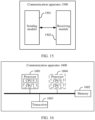
- a communication apparatus includes modules configured to perform the method according to the first aspect, such as a processing module and a transceiver module.
- the processing module is configured to determine a first transmission delay, where the first transmission delay is used to represent a round-trip transmission latency requirement of service data in a network.
- the transceiver module is configured to send the first transmission delay to a policy control network element, where the first transmission delay is used by the policy control network element to determine, based on the first transmission delay, delay budget information for transmitting the service data, and the delay budget information indicates an uplink transmission delay budget and/or a downlink transmission delay budget.
- the processing module is further configured to obtain a second transmission delay, adjust an application server processing delay based on the second transmission delay, and update the first transmission delay based on one or more of a service end-to-end delay, a terminal processing delay, and the application server processing delay.
- the second transmission delay is a round-trip transmission latency currently supported by the network.
- the transceiver module is further configured to send an updated first transmission delay to the policy control network element.
- the processing module is specifically configured to receive, by using the transceiver module, the second transmission delay from the policy control network element, where the second transmission delay is determined based on the network transmission delay information.
- the processing module is specifically configured to receive, by using the transceiver module, network transmission delay information from the policy control network element, and determine the second transmission delay based on the network transmission delay information.
- the processing module determines that the first transmission delay is greater than or equal to a first delay threshold.
- the transceiver module may include a sending module and a receiving module.
- the sending module is configured to implement a sending function of the communication apparatus according to the fifth aspect
- the receiving module is configured to implement a receiving function of the communication apparatus according to the fifth aspect.
- the communication apparatus may further include a storage module, and the storage module stores a program or instructions.
- the processing module executes the program or the instructions, the communication apparatus is enabled to perform the communication method according to the first aspect.
- the communication apparatus may be a network device, such as an application server, may be a chip (system) or another part or component that may be disposed in the network device, or may be an apparatus including the network device. This is not limited in this application.
- a communication apparatus includes modules configured to perform the method according to the second aspect, such as a processing module and a transceiver module.
- the processing module is configured to: obtain a first transmission delay, where the first transmission delay is used to represent a round-trip transmission latency requirement of service data in a network; and determine, based on the first transmission delay, delay budget information for transmitting the service data.
- the delay budget information indicates an uplink transmission delay budget and/or a downlink transmission delay budget.
- the transceiver module is configured to send the delay budget information to a session management network element.
- the processing module is specifically configured to send, by using the transceiver module, the first transmission delay to a network data analytics network element, and receive the delay budget information from the network data analytics network element, where the delay budget information is determined based on the first transmission delay.
- the processing module is specifically configured to: obtain network transmission delay information, where the network transmission delay information indicates an uplink transmission delay supported by the network and/or a downlink transmission delay supported by the network; and determine, based on the current first transmission delay and the network transmission delay information, the delay budget information for transmitting the service data.
- the processing module is further configured to: obtain the network transmission delay information, where the network transmission delay information indicates the uplink transmission delay supported by the network and/or the downlink transmission delay supported by the network; and when determining, based on the network transmission delay information, that the network cannot support the first transmission delay, determine a second transmission delay based on the network transmission delay information, where the second transmission delay is a round-trip transmission latency currently supported by the network.
- the transceiver module is further configured to send the second transmission delay to an application server, and receive an updated first transmission delay from the application server. The updated first transmission delay is determined based on the second transmission delay.
- the processing module is further configured to: obtain the network transmission delay information, where the network transmission delay information indicates the uplink transmission delay supported by the network and/or the downlink transmission delay supported by the network; and when determining, based on the network transmission delay information, that the network cannot support the first transmission delay, send the network transmission delay information to an application server, where the network transmission delay information is used to determine a second transmission delay, and the second transmission delay is a round-trip transmission latency currently supported by the network.
- the transceiver module is further configured to receive an updated first transmission delay from the application server. The updated first transmission delay is determined based on the second transmission delay.
- the processing module is specifically configured for a policy control network element to determine, according to the first transmission delay and a delay allocation policy, the delay budget information for transmitting the service data.
- the delay allocation policy indicates an association relationship between the uplink transmission delay budget and the downlink transmission delay budget.
- the transceiver module may include a sending module and a receiving module.
- the sending module is configured to implement a sending function of the communication apparatus according to the sixth aspect
- the receiving module is configured to implement a receiving function of the communication apparatus according to the sixth aspect.
- the communication apparatus may further include a storage module, and the storage module stores a program or instructions.
- the processing module executes the program or the instructions, the communication apparatus is enabled to perform the communication method according to the second aspect.
- the communication apparatus may be a network device, such as an application server, may be a chip (system) or another part or component that may be disposed in the network device, or may be an apparatus including the network device. This is not limited in this application.
- a communication apparatus includes modules configured to perform the method according to the third aspect, such as a receiving module and a sending module.
- the sending module is configured to send a delay reporting policy to a radio access network element and/or a user plane function network element.
- the delay reporting policy indicates a sending rule of network transmission delay information
- the network transmission delay information indicates an uplink transmission delay supported by a network and/or a downlink transmission delay supported by the network.
- the receiving module is configured to receive the network transmission delay information.
- the sending module is further configured to send the network transmission delay information to a policy control network element.
- the network transmission delay information is used by the policy control network element to determine delay budget information for transmitting service data.
- the delay reporting policy includes one or more of the following: a reporting periodicity, a reporting delay threshold, or a reported event.
- the sending module and the receiving module may be integrated into one module, for example, a transceiver module.
- the transceiver module is configured to implement a sending function and a receiving function of the communication apparatus.
- the communication apparatus may further include a processing module.
- the processing module is configured to implement a processing function of the communication apparatus.
- the communication apparatus may further include a storage module, and the storage module stores a program or instructions.
- the processing module executes the program or the instructions, the communication apparatus is enabled to perform the communication method according to the third aspect.
- the communication apparatus may be a network device, such as an application server, may be a chip (system) or another part or component that may be disposed in the network device, or may be an apparatus including the network device. This is not limited in this application.
- a communication apparatus includes modules configured to perform the method according to the fourth aspect, such as a processing module and a transceiver module.
- the transceiver module is configured to receive a delay reporting policy from a session management network element.
- the delay reporting policy indicates a sending rule of network transmission delay information
- the network transmission delay information indicates an uplink transmission delay supported by a network and/or a downlink transmission delay supported by the network.
- the processing module is configured to send the network transmission delay information according to the delay reporting policy.
- the delay reporting policy includes one or more of the following: a reporting periodicity, a reporting delay threshold, or a reported event.
- the transceiver module is specifically configured for a radio access network element to send the network transmission delay information based on the reporting periodicity.
- the transceiver module is specifically configured for the radio access network element to send the network transmission delay information in a case in which the network transmission delay information is greater than or equal to the reporting delay threshold.
- the transceiver module is specifically configured for the radio access network element to send the network transmission delay information in a case in which the reported event is that the radio access network element cannot support a current first transmission delay.
- the transceiver module is further configured to receive delay budget information for transmitting service data.
- the delay budget information indicates an uplink transmission delay budget and/or a downlink transmission delay budget.
- the processing module is further configured to determine, based on the delay budget information, an air interface resource used to transmit the service data.
- the processing module is further configured to adjust, based on the delay budget information, an air interface resource used to transmit the service data.
- the transceiver module may include a sending module and a receiving module.
- the sending module is configured to implement a sending function of the communication apparatus according to the eighth aspect
- the receiving module is configured to implement a receiving function of the communication apparatus according to the eighth aspect.
- the communication apparatus may further include a storage module, and the storage module stores a program or instructions.
- the processing module executes the program or the instructions, the communication apparatus is enabled to perform the communication method according to the fourth aspect.
- the communication apparatus may be a network device, such as an application server, may be a chip (system) or another part or component that may be disposed in the network device, or may be an apparatus including the network device. This is not limited in this application.
- a communication apparatus configured to perform the communication method according to any one of the implementations of the first aspect to the fourth aspect.
- the communication apparatus may be a network device, a chip (system) or another part or component that may be disposed in the network device, or an apparatus that includes the network device.
- the communication apparatus includes a corresponding module, unit, or means (means) for implementing the communication method according to any one of the first aspect to the fourth aspect.
- the module, unit, or means may be implemented by hardware, may be implemented by software, or may be implemented by hardware executing corresponding software.
- the hardware or software includes one or more modules or units configured to perform functions related to the foregoing communication method.
- a communication apparatus includes a processor, and the processor is configured to perform the communication method according to any one of the possible implementations of the first aspect to the fourth aspect.
- the communication apparatus may further include a transceiver.
- the transceiver may be a transceiver circuit or an interface circuit.
- the transceiver may be used by the communication apparatus according to the tenth aspect to communicate with another communication apparatus.
- the communication apparatus may further include a memory.
- the memory and the processor may be integrated together, or may be disposed separately.
- the memory may be configured to store a computer program and/or data related to the communication method according to any one of the first aspect to the fourth aspect.
- the communication apparatus may be a network device, a chip (system) or another part or component that may be disposed in the network device, or an apparatus that includes the network device.
- a communication apparatus includes a processor.
- the processor is coupled to a memory, and is configured to execute a computer program stored in the memory, to enable the communication apparatus to perform the communication method according to any one of the possible implementations of the first aspect to the fourth aspect.
- the communication apparatus according to the eleventh aspect may further include a transceiver.
- the transceiver may be a transceiver circuit or an interface circuit.
- the transceiver may be used by the communication apparatus according to the eleventh aspect to communicate with another communication apparatus.
- the communication apparatus may be a network device, a chip (system) or another part or component that may be disposed in the network device, or an apparatus that includes the network device.
- a communication apparatus including a processor and a memory.
- the memory is configured to store a computer program, and when the processor executes the computer program, the communication apparatus is enabled to perform the communication method according to any one of the implementations of the first aspect to the fourth aspect.
- the communication apparatus may further include a transceiver.
- the transceiver may be a transceiver circuit or an interface circuit.
- the transceiver may be used by the communication apparatus according to the twelfth aspect to communicate with another communication apparatus.
- the communication apparatus may be a network device, a chip (system) or another part or component that may be disposed in the network device, or an apparatus that includes the network device.
- a communication apparatus including a processor.
- the processor is coupled to a memory. After reading a computer program in the memory, the processor is configured to perform, based on the computer program, the communication method according to any one of the implementations of the first aspect to the fourth aspect.
- the communication apparatus according to the thirteenth aspect may further include a transceiver.
- the transceiver may be a transceiver circuit or an interface circuit.
- the transceiver may be used by the communication apparatus according to the thirteenth aspect to communicate with another communication apparatus.
- the communication apparatus may be a network device, a chip (system) or another part or component that may be disposed in the network device, or an apparatus that includes the network device.
- a processor is provided.
- the processor is configured to perform the communication method according to any one of the possible implementations of the first aspect to the fourth aspect.
- a communication system includes one or more terminal devices and one or more network devices such as an application server, a policy control network element, a session management network element, and a radio access network element.
- a computer-readable storage medium including a computer program or instructions.
- the computer program or the instructions When the computer program or the instructions are run on a computer, the computer is enabled to perform the communication method according to any one of the possible implementations of the first aspect to the fourth aspect.
- a computer program product including a computer program or instructions.
- the computer program or the instructions are run on a computer, the computer is enabled to perform the communication method according to any one of the possible implementations of the first aspect to the fourth aspect.
- FIG. 1 is a schematic diagram of a 5GS architecture. As shown in FIG. 1 , the 5GS includes an access network (access network, AN) and a core network (core network, CN), and may further include a terminal.
- access network access network
- core network core network
- the CN may include a user plane function (user plane function, UPF) network element (user plane network element for short), an access and mobility management function (access and mobility management function, AMF) network element, a session management function (session management function, SMF) network element (session management network element for short), an authentication server function (authentication server function, AUSF) network element, a network data analytics function (network data analytics function, NWDAF) network element (network data analytics network element for short), a network exposure function (network exposure function, NEF) network element, a network function storage function (network exposure function Repository Function, NRF) network element, a policy control function (policy control function, PCF) network element (policy control network element for short), a unified data management (unified data management, UDM) network element (data management network element for short), an application function (application function, AF) network element, a service communication proxy (service communication proxy, SCP) network element, or the like.
- UPF user plane function
- AMF access and mobility management function
- FIG. 1 merely provides some examples of network elements or entities in a 5G network.
- the 5G network may further include some network elements or entities that are not shown in FIG. 1 , such as a unified data repository (unified data repository, UDR) network element, a network slice selection function (network slice selection function, NSSF) network element, and a charging function (charging function, CHF) network element.
- UDR unified data repository
- NSSF network slice selection function
- CHF charging function
- a terminal device accesses the 5G network by using an AN device, and communicates with the AMF network element through an N1 interface (N1 for short).
- ARAN device communicates with the AMF network element through an N2 interface (N2 for short).
- the RAN device communicates with the UPF network element through an N3 interface (N3 for short).
- the SMF network element communicates with the UPF network element through an N4 interface (N4 for short), and the UPF network element accesses a data network (data network, DN) through an N6 interface (N6 for short).
- a control plane function such as the AUSF network element, the AMF network element, the SMF network element, the NEF network element, the NRF network element, the PCF network element, the UDM network element, the UDR network element, the AF network element, the NWDAF network element, or the SCP network element shown in FIG. 1 performs interaction through a service-based interface.
- a service-based interface exhibited by the AUSF network element is Nausf
- a service-based interface exhibited by the AMF network element is Namf
- a service-based interface exhibited by the SMF network element is Nsmf
- a service-based interface exhibited by the NEF network element is Nnef
- a service-based interface exhibited by the NRF network element is Nnrf
- a service-based interface exhibited by the PCF network element is Npcf
- a service-based interface exhibited by the UDM network element is Nudm
- a service-based interface exhibited by the AF network element is Naf.
- a service-based interface exhibited by the UDR network element is Nudr
- a service-based interface exhibited by the NSSF network element is Nnssf
- a service-based interface exhibited by the CHF network element is Nchf.
- 5G system architecture 5G system architecture
- An end-to-end (end to end) delay may also be referred to as a motion to photon (motion to photon, MTP) delay.
- MTP motion to photon
- the end-to end delay is a delay from detecting a head motion and/or a hand motion by a terminal to rendering and displaying a corresponding new picture on a screen of the terminal.
- the end-to end delay is a time length between a moment at which the terminal sends uplink data and a moment at which downlink data (for example, a processing result corresponding to the uplink data) arrives at a terminal device.
- the terminal collects user-related data, and sends the user-related data to an application server for processing, to obtain processed data from the application server.
- the VR service is used as an example.
- the terminal collects action information of a user, for example, information about a head action (for example, a head rotation), a hand action, a squatting action, or a stand-up action, and sends the information to the application server by using a communication network.
- the application server performs image rendering based on the action information of the user, and sends a rendered image to the terminal by using the communication network, to provide the rendered image for the user to watch.
- the VR service is used as an example.
- the terminal may be a VR device, for example, a wearable VR head mounted display, and the end-to-end delay may be the MTP delay.
- the end-to-end delay may be the MTP delay.
- an MTP delay of service data of the VR service needs to be within 20 milliseconds (millisecond, ms).
- an air interface transmission delay may be determined based on time and the end-to-end delay.
- the air interface transmission delay includes an uplink air interface transmission delay between the terminal and a radio access network element and/or a downlink air interface transmission delay between the radio access network element and the terminal.
- the data sent by the terminal carries uplink sending time.
- the application server, a user plane network element, or the like determines a downlink delay budget based on the uplink sending time, and then adjusts an air interface resource of the radio access network element based on the downlink delay budget.
- a communication system includes a terminal, a radio access network device, a user plane network element, and an application server, and service data is transmitted in a form of a data packet.
- a data packet from the terminal to the communication network is an uplink data packet
- a data packet from the communication network to the terminal is a downlink data packet.
- the uplink data packet may include action information transmitted from the terminal to the communication network.
- the downlink data packet may include rendering information transmitted from the communication network to the terminal.
- a terminal sends an uplink data packet, where the uplink data packet carries uplink sending time and an end-to-end delay.
- a radio access network element receives and sends the uplink data packet from the terminal.
- a user plane network element receives the uplink data packet from the radio access network element.
- the user plane network element stores the uplink sending time and the end-to-end delay in the uplink data packet, and obtains a time point at which the uplink data packet is received.
- the user plane network element sends the uplink data packet to an application server.
- the application server receives and processes the uplink data packet from the user plane network element, to obtain processed data.
- the application server sends a downlink data packet, where the downlink data packet includes the processed data.
- the user plane network element receives the downlink data packet from the application server, and records downlink receiving time of the downlink data packet.
- the user plane network element determines a delay budget based on the downlink receiving time of the downlink data packet, an end-to-end delay requirement, and the uplink sending time.
- the user plane network element sends the downlink data packet, where the downlink data packet includes the downlink sending time and a downlink packet delay budget of the downlink data packet.
- the radio access network element schedules an air interface resource based on the downlink packet delay budget. Clocks of the terminal, the radio access network element, and the user plane network element are synchronized.
- a terminal may send decoding time, display quality, and an end-to-end delay to an application server by using an application layer.
- the terminal sends an uplink data packet, where the uplink data packet carries uplink sending time and the end-to-end delay.
- a radio access network element receives and sends the uplink data packet from the terminal.
- a user plane network element receives the uplink data packet from the radio access network element, and sends the uplink data packet to the application server.
- the application server receives the uplink data packet from the user plane network element.
- the application server obtains a downlink delay budget of the downlink data packet based on the uplink sending time and the end-to-end delay in the uplink data packet.
- the application server processes the uplink data packet to obtain a processing result of the uplink data packet.
- the application server sends the downlink data packet, where the downlink data packet includes a processing result and the downlink delay budget.
- the user plane network element receives the downlink data packet from the application server, and sends the downlink data packet to the radio access network element, where the downlink data packet includes downlink sending time of the downlink data packet and a downlink packet delay budget.
- the radio access network element schedules an air interface resource based on the downlink packet delay budget. Clocks of the terminal, the radio access network element, the user plane network element and the application server are synchronized.
- the radio access network element needs to frequently adjust a data processing policy for each piece of downlink data (for example, the downlink data packet), for example, scheduling the air interface resource. Consequently, a data processing process is complex, and it is difficult to ensure processing efficiency and a processing delay.
- embodiments of this application provide the following technical solutions, to ensure the data processing efficiency and the data processing delay.
- a wireless fidelity (wireless fidelity, Wi-Fi) system a vehicle to everything (vehicle to everything, V2X) communication system
- a device-to-device (device-to-device, D2D) communication system an internet of vehicles communication system
- 4th generation (4th generation, 4G) mobile communication system such as a long term evolution (long term evolution, LTE) system and a worldwide interoperability for microwave access (worldwide interoperability for microwave access, WiMAX) communication system
- a 5th generation (5th generation, 5G) mobile communication system such as a new radio (new radio, NR) system
- a future communication system such as a 6th generation (6th generation, 6G) mobile communication system.
- a network architecture and a service scenario described in embodiments of this application are intended to describe the technical solutions in embodiments of this application more clearly, and do not constitute a limitation on the technical solutions provided in embodiments of this application.
- a person of ordinary skill in the art may know that: With the evolution of the network architecture and the emergence of new service scenarios, the technical solutions provided in embodiments of this application are also applicable to similar technical problems.
- FIG. 4 is a schematic diagram of an architecture of a communication system to which a communication method according to an embodiment of this application is applicable.
- the communication system may be applicable to the foregoing 5GS, and includes a radio access network element, a session management network element, a policy control network element, and an application server.
- the policy control network element may be a PCF network element
- the session management network element may be an SMF network element.
- the communication system may further include another network element, for example, a network data analytics function network element, a network exposure function network element, or a user plane network element.
- another network element for example, a network data analytics function network element, a network exposure function network element, or a user plane network element.
- radio access network element for related functions of the radio access network element, the session management network element, the policy control network element, the network data analytics function network element, the network exposure function network element, and the user plane network element, refer to related descriptions in the foregoing 5GS. Details are not described again.
- the application server may be a device having a data processing function (for example, image rendering) and receiving and sending functions, or a chip or a chip system that may be disposed in the device.
- the application server may be a system including a device having a data processing function and receiving and sending functions.
- the application server may also be referred to as a cloud server.
- the application server may be configured to process service data.
- the policy control network element may configure, for the radio access network element by using the session management network element, an uplink transmission delay budget and/or a downlink transmission delay budget corresponding to a service, or an uplink transmission delay budget and/or a downlink transmission delay budget that meet/meets a transmission delay requirement of the service.
- a terminal or an access network device may adjust, based on an uplink transmission delay and/or a downlink transmission delay, an air interface resource used to transmit the service data, to avoid adjusting an air interface resource for each data packet. In this way, data processing complexity is reduced, and data processing efficiency and a data processing delay are ensured.
- the solutions in embodiments of this application may also be applied to another communication system, and a corresponding name may also be replaced with a name of a corresponding function in the another communication system.
- the communication system in this embodiment of this application may further include a network structure or a terminal that is not shown in FIG. 4 . Details are not described herein again.
- a radio access network element is a RAN network element
- a session management network element is an SMF network element
- a policy control network element is a PCF network element
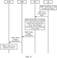
- FIG. 6 is a schematic flowchart 1 of a communication method according to an embodiment of this application.
- a PCF network element may receive, from an NWDAF network element based on a first transmission delay that is determined by an AS and that is used to represent a round-trip transmission latency requirement of service data, delay budget information used to transmit the service data, and send the delay budget information to an SMF network element.
- the delay budget information indicates an uplink transmission delay budget and/or a downlink transmission delay budget.
- the SMF network element configures the delay budget information for a RAN network element, and a RAN schedules an air interface resource based on the delay budget information.
- a procedure of the communication method is as follows: S601: An AS determines a first transmission delay.
- the first transmission delay is used to represent a round-trip transmission latency requirement of service data in a network.
- the service data may include data transmitted by a terminal to the AS and data transmitted by the AS to the terminal.
- the service data may include action information and rendering information in the VR service.
- a round-trip transmission latency may be a sum of a delay of transmitting the service data from the terminal to the AS and a delay of transmitting the service data from the AS to the terminal.
- the round-trip transmission latency may be a sum of a delay of transmitting the action information from the terminal to the AS and a delay of transmitting the rendering information from the AS to the terminal.
- the end-to-end delay is related to a service.
- the end-to-end delay may be determined based on the service.
- the end-to-end delay may be 20 ms.
- the terminal processing delay is a delay of processing the service data by the terminal, and may be obtained from the terminal.
- the AS interacts with the terminal at an application layer, to obtain the terminal processing delay.
- the application server processing delay (hereinafter referred to as an AS processing delay) may be determined based on a processing delay that is on the AS and that is of the service data that has been transmitted.
- the AS processing delay may be an average value of the processing delays that are on the AS and that are of the service data that has been transmitted.
- the AS processing delay may be determined based on a current load of the AS.
- the AS may determine the AS processing delay based on a correspondence between the AS processing delay and the current load of the AS. This is not specifically limited herein.
- the round-trip transmission latency requirement may be a range of a round-trip transmission latency that meets a service requirement, namely, a range of the sum of the delay of transmitting the service data from the terminal to the AS and the delay of transmitting the service data from the AS to the terminal.
- the round-trip transmission latency requirement may be a range of the sum of the delay of transmitting the action information from the terminal to the AS and the delay of transmitting the rendering information from the AS to the terminal.
- the first transmission delay may be a maximum round-trip transmission latency that meets the round-trip transmission latency requirement of the service data.
- that the AS determines the first transmission delay may be that the AS determines the round-trip transmission latency based on one or more of the service end-to-end delay, the terminal processing delay, and the AS processing delay.
- An example in which the AS determines the round-trip transmission latency based on the service end-to-end delay, the terminal processing delay, and the application server processing delay is used.
- a transmission delay threshold may be set in the AS.
- the first transmission delay may be greater than or equal to the transmission delay threshold.
- the first transmission delay is the maximum round-trip transmission latency corresponding to the round-trip transmission latency requirement of the service data, and is greater than or equal to the transmission delay threshold.
- the processing delay threshold may be 20 ms, 30 ms, or 40 ms.
- a specific implementation may be determined based on service data processed by the application server, and details are not described herein again.
- S602 The AS sends the first transmission delay to the PCF network element.
- the PCF network element receives the first transmission delay from the AS.
- the first transmission delay may be exchanged through an interface between the AS and the PCF network element, or may be forwarded by using another network element (for example, a network capability exposure network element NEF). This is not limited in this application.
- NEF network capability exposure network element
- the AS may alternatively send a transmission delay requirement to the PCF network element by using another network element such as the NEF network element. This is not limited herein.
- the AS may have a plurality of services, which may include a service that needs end-to-end delay assurance (end-to-end delay requirement) and/or a service that does not need the end-to-end delay assurance.
- the PCF network element may determine, based on whether a message sent by the AS carries the first transmission delay, whether delay budget information needs to be further determined.
- the PCF network element may send a request message to a related network element (for example, an SMF network element, a UPF network element, or a RAN network element), to request the related network element to send network transmission delay information to the NEF network element (or the PCF network element).
- the network transmission delay information may be used by the PCF network element to determine the delay budget information.
- the RAN network element sends the network transmission delay information to the UPF network element.
- the UPF network element receives the transmission delay information from the RAN network element.
- the uplink transmission delay supported by the network may include an uplink air interface transmission delay supported by the network and an uplink transmission delay between the UPF network element and the RAN network element, for example, an uplink transmission delay of an N3 interface.
- the downlink transmission delay supported by the network may include a downlink air interface transmission delay supported by the network and a downlink transmission delay between the UPF network element and the RAN network element, for example, a downlink transmission delay of the N3 interface.
- Uplink transmission delay supported by the network uplink air interface transmission delay supported by the network + uplink transmission delay between the UPF network element and the RAN network element (uplink transmission delay of the N3 interface).
- Downlink transmission delay supported by the network downlink air interface transmission delay supported by the network + downlink transmission delay between the UPF network element and the RAN network element (downlink transmission delay of the N3 interface).
- an uplink air interface transmission delay needed for transmitting a piece of service data is determined based on a quantity of currently accessed service flows, a bandwidth requirement of each service flow, and a currently available air interface resource.
- the network transmission delay information may be obtained based on a resource status.
- an uplink air interface transmission delay needed for transmitting a piece of service data is determined based on a quantity of currently accessed service flows, a bandwidth requirement of each service flow, and a currently available air interface resource.
- the network transmission delay information may be obtained by preconfiguring a parameter.
- the RAN network element preconfigures the uplink transmission delay between the UPF network element and the RAN network element, for example, the uplink transmission delay of an N3 interface.
- the new RAN network element reports, to the UPF network element, the preconfigured uplink transmission delay between the UPF network element and the RAN network element, for example, the uplink transmission delay of the N3 interface.
- the network transmission delay information may be obtained through real-time measurement of data packets one by one.
- the RAN network element may measure a transmission delay of each uplink data packet in real time by using time (for example, a timestamp) carried in the uplink data packet, and report an uplink air interface transmission delay obtained through the real-time measurement.
- the RAN network element may send the network transmission delay information based on a request message sent by the PCF network element or the SMF network element.
- the request message may be sent by the PCF network element when receiving the first transmission delay from the AS, or may be sent by the SMF network element after receiving the request message from the PCF.
- the RAN network element may send the network transmission delay information according to a delay reporting policy described in Scenario 4 or Scenario 5 of this application.
- the UPF network element sends the network transmission delay information to an NWDAF network element.
- the NWDAF network element receives the network transmission delay information from the UPF network element.
- the first transmission delay may be carried in a service-based interface message between the PCF network element and the NWDAF network element.
- the delay budget information indicates an uplink transmission delay budget and/or a downlink transmission delay budget.
- the delay budget information indicates the uplink transmission delay budget for transmitting the service data; the delay budget information indicates the downlink transmission delay budget for transmitting the service data; or the delay budget information indicates the uplink transmission delay budget and the downlink transmission delay budget for transmitting the service data.
- the delay budget information may indicate the uplink transmission delay budget for transmitting the service data; if the service has downlink service data, the delay budget information indicates the downlink transmission delay budget for transmitting the service data; or if the service has uplink service data and downlink service data that need to be transmitted, the delay budget information may indicate the uplink transmission delay budget for transmitting the service data and the downlink transmission delay budget for transmitting the service data.
- the delay budget information may carry an uplink air interface delay budget, and indicate the uplink transmission delay budget by using the uplink air interface delay budget and the uplink transmission delay between the UPF network element and the RAN network element, for example, the uplink transmission delay of the N3 interface.
- Uplink transmission delay budget uplink air interface delay budget + uplink transmission delay between the UPF network element and the RAN network element (for example, the uplink transmission delay of the N3 interface).
- the delay budget information may carry a downlink air interface transmission delay, and indicate the downlink transmission delay budget by using the downlink air interface transmission delay budget and the downlink transmission delay between the UPF network element and the RAN network element, for example, the downlink transmission delay of the N3 interface.
- Downlink transmission delay budget downlink air interface transmission delay budget + downlink transmission delay between the UPF network element and the RAN network element (for example, the downlink transmission delay of the N3 interface).
- the NWDAF network element sends the delay budget information to the PCF network element.
- the PCF network element receives the delay budget information from the NWDAF network element.
- the PCF network element receives the delay budget information from the NWDAF network element, so that overheads of a policy control network element can be reduced and running efficiency can be improved.
- the delay budget information may be carried in a QoS policy, to reuse an existing information element, reduce communication overheads, and improve communication efficiency.
- the delay budget information may alternatively be carried in any other possible information element. This is not specifically limited herein.
- the PCF network element may further send the delay reporting policy to the SMF network element, to indicate the SMF network element to report the network transmission delay information according to the delay reporting policy, to determine the delay budget information.
- the delay reporting policy may be at least one of a reporting periodicity, a reporting delay threshold, or a reported event. For details, refer to related descriptions in the following Scenario 4 or Scenario 5. Details are not described again.
- the delay reporting policy may be configured based on a service type and/or a service delay requirement.
- the reporting periodicity may be 5 minutes.
- the reported event may be that the network does not support the service delay requirement, for example, a radio access network element cannot support received delay budget information.
- the PCF network element may further send a delay reporting indication to the SMF network element, to indicate the SMF network element to report the network transmission delay information, to determine the delay budget information.
- the SMF network element may autonomously determine the delay reporting policy based on the delay reporting indication, and report the network transmission delay information.
- the delay reporting indication is used to trigger the SMF network element to determine the delay reporting policy and send the network transmission delay information according to the delay reporting policy.
- the delay reporting indication may be the request message in S603. For specific implementation, refer to related descriptions of S603. Details are not described herein again.
- a principle of determining the delay reporting policy by the SMF network element is similar to a principle of determining the delay reporting policy by the PCF network element. For details, refer to the principle of determining the delay reporting policy by the PCF network element. Details are not described again.
- the SMF network element sends the delay budget information to the RAN network element.
- the RAN network element receives the delay budget information from the SMF network element.
- the delay budget information may be carried in the QoS policy, to reuse the existing information element, reduce the communication overheads, and improve the communication efficiency.
- the delay budget information may alternatively be carried in any other possible information element. This is not specifically limited herein.
- the policy control network element determines the delay budget information based on the first transmission delay, and sends the delay budget information to a session management network element. For example, the policy control network element may send the delay budget information to the radio access network element by using the session management network element, to update the delay budget information of the radio access network element.
- the RAN network element adjusts an air interface resource based on the delay budget information.
- the RAN network element may adjust the air interface resource based on a correspondence between the delay budget information and the air interface resource, to enable the air interface resource to match the delay budget information, so that the network transmission delay can meet a service end-to-end delay requirement. For example, the RAN network element may allocate abundant uplink air interface transmission resources or downlink air interface transmission resources to the service data based on the delay budget information, to enable the service data to be sent within a given transmission delay budget.
- the first transmission delay is used to represent a round-trip transmission latency requirement of service data in a network.
- the round-trip transmission latency requirement may be a limitation on a round-trip transmission latency.
- the round-trip transmission latency requirement may be a limitation on a round-trip transmission latency.
- the first transmission delay may be a maximum round-trip transmission latency that meets the round-trip transmission latency requirement.
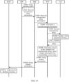
- S702 The AS sends the first transmission delay to a PCF network element.
- the PCF network element receives the first transmission delay from the AS.
- the PCF network element obtains a network transmission delay.
- the network transmission delay information indicates an uplink transmission delay supported by the network and/or a downlink transmission delay supported by the network.
- the network transmission delay information indicates an uplink transmission delay supported by the network and/or a downlink transmission delay supported by the network.
- the PCF network element may obtain the network transmission delay information from an SMF network element or an NWDAF network element.
- the PCF network element receives network transmission delay information from the SMF network element or the NWDAF network element, to obtain the network transmission delay information.
- the network transmission delay information of the SMF network element may be from a RAN network element.
- the network transmission delay information may be first sent by a RAN to a UPF network element, and then sent by the UPF network element to the SMF network element.
- the network transmission delay information of the NWDAF network element may also be from the RAN network element.
- the network transmission delay information may be first sent by the RAN network element to the UPF network element, and then sent by the UPF network element to the NWDAF network element.
- the PCF network element determines delay budget information based on the network transmission delay information and the first transmission delay.
- the delay budget information indicates an uplink transmission delay budget and/or a downlink transmission delay budget.
- the delay budget information indicates the uplink transmission delay budget for transmitting the service data; the delay budget information indicates the downlink transmission delay budget for transmitting the service data; or the delay budget information indicates the uplink transmission delay budget and the downlink transmission delay budget for transmitting the service data.
- the delay budget information indicates the uplink transmission delay budget and the downlink transmission delay budget for transmitting the service data.
- the PCF network element may further receive, from the UPF network element, an uplink transmission delay between the UPF network element and the RAN network element, for example, an uplink transmission delay of an N3 interface, and a downlink transmission delay between the UPF network element and the RAN network element, for example, a downlink transmission delay of the N3 interface.
- the uplink transmission delay between the UPF network element and the RAN network element and/or the downlink transmission delay between the UPF network element and the RAN network element may be obtained by the PCF network element from the UPF network element.
- a principle of determining the delay budget information by the PCF network element in S704 is similar to a principle of determining the delay budget information by the NWDAF network element in S606. For a specific implementation principle, refer to related descriptions of S606. Details are not described again.
- a policy control network element determines the delay budget information based on the first transmission delay and the network transmission delay information, so that dependence on another network element other than the policy control network element can be reduced and adaptability can be improved.
- the PCF network element sends the delay budget information to the SMF network element.
- the SMF network element receives the delay budget information from the PCF network element.
- the SMF network element sends the delay budget information to the RAN network element.
- the RAN network element receives the delay budget information from the SMF network element.
- the RAN network element adjusts an air interface resource based on the delay budget information.
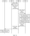
- FIG. 8 is a schematic flowchart 3 of a communication method according to an embodiment of this application.
- a PCF network element may receive, from an AS, a first transmission delay that is used to represent a round-trip transmission latency requirement of service data in a network.
- the PCF network element autonomously determines, according to a first transmission delay requirement and a delay allocation policy, delay budget information used to transmit the service data, and sends the delay budget information to an SMF network element.
- the delay budget information indicates an uplink transmission delay budget and/or a downlink transmission delay budget.
- the SMF network element configures the uplink transmission delay budget and/or the downlink transmission delay budget for a RAN network element.
- the delay budget information may be autonomously determined according to the delay allocation policy, to avoid using the network transmission delay information to determine the delay budget information, so that a procedure of determining the delay budget information is simplified and communication efficiency is improved.
- a procedure of the communication method is as follows: S801: An AS determines a first transmission delay.
- the first transmission delay is used to represent a round-trip transmission latency requirement of service data in a network.
- the service data may include data transmitted by a terminal to the AS and data transmitted by the AS to the terminal.
- data transmitted by the AS to the terminal For a specific implementation principle, refer to related descriptions of S701. Details are not described again.
- the first transmission delay may be a maximum round-trip transmission latency that meets the round-trip transmission latency requirement.
- S802 The AS sends the first transmission delay to a PCF network element.
- the PCF network element receives the first transmission delay from the AS.
- the PCF network element determines, according to a delay allocation policy and the first transmission delay, delay budget information for transmitting the service data.
- the delay allocation policy indicates an association relationship, for example, a proportion, between an uplink transmission delay budget and a downlink transmission delay budget.
- the delay distribution policy may be configured on the PCF network element.
- the delay distribution policy may be obtained by the PCF network element from another network element, for example, obtained by the PCF network element from an SMF network element after receiving the first transmission delay.
- the delay budget information indicates the uplink transmission delay budget and/or the downlink transmission delay budget.
- the delay budget information indicates the uplink transmission delay budget for transmitting the service data;
- the delay budget information indicates the downlink transmission delay budget for transmitting the service data; or the delay budget information indicates the uplink transmission delay budget and the downlink transmission delay budget for transmitting the service data.
- the delay budget information indicates the uplink transmission delay budget and the downlink transmission delay budget for transmitting the service data.
- the first transmission delay is 20 ms. If the delay allocation policy configured on the PCF indicates that the proportion between the uplink transmission delay budget and the downlink transmission delay budget is 1:3, the uplink transmission delay is 5 ms, and the downlink transmission delay is 15 ms.
- the PCF network element sends the delay budget information to the SMF network element.
- the SMF network element receives the delay budget information from the PCF network element.
- the SMF network element sends the delay budget information to a RAN network element.
- the RAN network element receives the delay budget information from the SMF network element.
- the RAN network element adjusts an air interface resource based on the delay budget information.
- FIG. 9 is a schematic flowchart 4 of a communication method according to an embodiment of this application.
- a RAN network element or a UPF network element may receive a delay reporting policy from an SMF network element, the RAN network element or the UPF network element may send network transmission delay information to the SMF network element according to the delay reporting policy from the SMF network element, and the SMF network element sends the network transmission delay information to a NEF network element or a PCF network element.
- the NEF network element or the PCF network element sends the network transmission delay information to an AS, and the AS determines a first transmission delay based on the network transmission delay information, to adjust an air interface resource of a RAN.
- the delay reporting policy in Scenario 4 may be carried in the delay budget information sent by the SMF network element to the RAN network element in Scenario 1 to Scenario 3.
- S901 An SMF network element sends a delay reporting policy to a RAN network element.
- the RAN network element receives the delay reporting policy from the SMF network element.
- the delay reporting policy may be carried in a QoS policy.
- the delay reporting policy and the delay budget information in S609, S706, or S805 may be carried in a same QoS policy.
- the delay reporting policy may alternatively be carried in another information element, for example, in separate delay reporting policy indication information. This is not limited herein.
- the SMF network element may receive the delay reporting policy from a PCF network element, or may determine the delay reporting policy based on a delay reporting indication sent by the PCF network element, and send the delay reporting policy to the RAN network element.
- the SMF network element may receive the delay reporting policy from a PCF network element, or may determine the delay reporting policy based on a delay reporting indication sent by the PCF network element, and send the delay reporting policy to the RAN network element.
- the network transmission delay information indicates an uplink transmission delay supported by a network and/or a downlink transmission delay supported by the network.
- the network transmission delay information indicates an uplink transmission delay supported by a network and/or a downlink transmission delay supported by the network.
- the network transmission delay information sent by the RAN network element may be carried in a GTP-U data packet header.
- a radio access network element may send the network transmission delay information according to the sending rule in the delay reporting policy, to reduce a frequency of sending the network transmission delay information and a frequency of updating the first transmission delay, so that data processing complexity can be reduced and data processing efficiency is improved.
- the RAN network element may send the network transmission delay information to the SMF network element at an interval of a time length of each reporting periodicity, to reduce the frequency of sending the network transmission delay information and the frequency of updating the first transmission delay, so that data processing complexity can be reduced and data processing efficiency is improved.
- the RAN network element may send the network transmission delay information to the SMF network element based on the reporting delay threshold, to reduce the frequency of sending the network transmission delay information and the frequency of updating the first transmission delay, so that data processing complexity can be reduced and data processing efficiency is improved. For example, if the reporting delay threshold is determined based on the air interface uplink transmission delay, and the reporting delay threshold is 5 ms, in the network transmission delay information, when the air interface uplink transmission delay is greater than or equal to 5 ms, the RAN network element may send the network transmission delay information to the SMF network element.
- the delay reporting policy includes the reporting periodicity or the reporting delay threshold
- the frequency of sending the network transmission delay information may be reduced, so that a network load is reduced.
- the frequency of determining the first transmission delay may be further reduced, so that a data processing volume can be further reduced and the data processing efficiency is improved.
- the SMF network element sends the network transmission delay information to a NEF network element.
- the NEF network element receives the network transmission delay information.
- the network transmission delay information may be carried in a service-based interface message between the SMF network element and the NEF network element.
- the SMF network element may send the network transmission delay information to the NEF network element based on the delay reporting threshold.
- the SMF network element may filter the network transmission delay information based on the delay reporting threshold.
- the NEF network element sends the network transmission delay information to an AS.
- the AS receives the network transmission delay information from a NEF.
- the network transmission delay information may be carried in a service-based interface message between an AS network element and the NEF network element.
- S905 The AS adjusts an AS processing delay based on the network transmission delay information.
- an adjusted AS processing delay may be less than or equal to 12 ms.
- S906 The AS determines the first transmission delay based on the AS processing delay.
- AS processing delay in S906 is an adjusted AS delay in S905.
- S907 The AS sends the first transmission delay to the PCF network element.
- the PCF network element receives the first transmission delay from the AS.
- the PCF network element determines the delay budget information based on the first transmission delay.
- the delay budget information indicates an uplink transmission delay budget and/or a downlink transmission delay budget.
- the delay budget information indicates the uplink transmission delay budget for transmitting service data; the delay budget information indicates the downlink transmission delay budget for transmitting service data; or the delay budget information indicates the uplink transmission delay budget and the downlink transmission delay budget for transmitting service data.
- the delay budget information indicates the uplink transmission delay budget and the downlink transmission delay budget for transmitting service data.
- steps S903 and S904 may be alternatively implemented by the PCF network element. Details are not described herein again.
- FIG. 10 is a schematic flowchart 5 of a communication method according to an embodiment of this application.
- the RAN network element may report network transmission delay information according to the delay reporting policy from the SMF network element.
- a PCF determines, based on the network transmission delay information, that a network cannot support a delay indicated by the delay budget information obtained according to the method in Scenario 1 to Scenario 4. In this way, the PCF may update a first transmission delay based on the network transmission delay information, and re-determine the delay budget information.
- S1001 An SMF network element sends a delay reporting policy to a UPF network element.
- the UPF network element receives the delay reporting policy from the SMF network element.
- the delay reporting policy may be carried in a QoS policy.
- the delay reporting policy and the delay budget information in S609, S706, or S805 may be carried in a same QoS policy.
- the delay reporting policy may alternatively be carried in another information element, for example, in a separate delay reporting policy indication information. This is not limited herein.
- the SMF network element may receive the delay reporting policy from a PCF network element, or may determine the delay reporting policy based on a delay reporting indication sent by the PCF network element, and send the delay reporting policy to the UPF network element.
- the SMF network element may receive the delay reporting policy from a PCF network element, or may determine the delay reporting policy based on a delay reporting indication sent by the PCF network element, and send the delay reporting policy to the UPF network element.
- the UPF network element sends the network transmission delay information according to the delay reporting policy.
- the SMF network element receives the network transmission delay information from the UPF network element.
- the network transmission delay information indicates an uplink transmission delay supported by a network and/or a downlink transmission delay supported by the network.
- the network transmission delay information indicates an uplink transmission delay supported by a network and/or a downlink transmission delay supported by the network.
- the network transmission delay information may be carried in an N4 interface message between the SMF network element and the UPF network element.
- the UPF network element may obtain the network transmission delay information from a RAN network element, and send the network transmission delay information to the SMF network element when detecting that the radio access network element cannot support the received delay budget information.
- S 1001 or S 1002 may alternatively be implemented by the RAN network element. Details are not described herein again.
- the network transmission delay information sent by the RAN network element may be carried in a GTP-U data packet header.
- the network transmission delay information may be sent in a case in which the radio access network element cannot support the received delay budget information, to reduce a frequency of sending the network transmission delay information, and reduce a network load.
- a frequency of determining a first transmission delay may be further reduced, so that a data processing volume may be further reduced, and data processing efficiency is improved.
- the SMF network element sends the network transmission delay information to the PCF network element.
- the PCF network element receives the network transmission delay information.
- the network transmission delay information may be carried in a service-based interface message between the SMF network element and the PCF network element.
- the PCF network element determines a second transmission delay based on the network transmission delay information.
- the second transmission delay is determined based on the uplink transmission delay supported by the network and/or the downlink transmission delay supported by the network in the network transmission delay information. For example, if the network transmission delay information indicates that the uplink transmission delay supported by the network is 3 ms to 5 ms, and the downlink transmission delay supported by the network is 5 ms to 15 ms, the second transmission delay is 8 ms to 20 ms.
- the PCF network element may perform S1004 when it is difficult to meet a service requirement by updating the delay budget information (adjusting only the delay budget information).
- the PCF network element may perform S1004 when determining, based on the network transmission delay information, that the network cannot support the first transmission delay (for example, the first transmission delay obtained according to Scenario 1 to Scenario 4).
- an air interface transmission delay requirement is not greater than 20 ms
- an uplink air interface transmission delay requirement and a downlink air interface transmission delay requirement are respectively 5 ms and 15 ms.
- an uplink air interface transmission delay supported by the RAN network element is 6 ms to 8 ms, and a downlink air interface transmission delay supported by the RAN network element is 15 ms to 17 ms, it is difficult to meet a delay requirement of 20 ms by updating the delay budget information.
- S1004 may be performed.
- the application server may correspondingly adjust an application server processing delay based on a change of a network transmission delay, to enable the application server processing delay to match a network round-trip transmission latency supported by the network, and enable the network round-trip transmission latency to meet a service end-to-end delay requirement.
- the PCF network element sends the second transmission delay to the AS.
- the AS receives the second transmission delay from the PCF network element.
- the second transmission delay may be carried in a service-based interface message between the AS network element and the PCF network element.
- the PCF may send the second transmission delay to the AS by using a NEF network element.
- the application server receives the second transmission delay from a policy control network element, so that overheads of the application server can be reduced, and running efficiency can be improved.
- the AS determines an updated first transmission delay based on the second transmission delay, in other words, updates the first transmission delay.
- S1007 The AS sends the updated first transmission delay to the PCF network element.
- the PCF network element receives the updated first transmission delay from the AS.
- the PCF network element determines, based on the updated first transmission delay, the delay budget information for transmitting service data.
- the delay budget information indicates the uplink transmission delay budget and/or the downlink transmission delay budget.
- the delay budget information indicates the uplink transmission delay budget for transmitting the service data;
- the delay budget information indicates the downlink transmission delay budget for transmitting the service data; or
- the delay budget information indicates the uplink transmission delay budget and the downlink transmission delay budget for transmitting the service data.
- the PCF network element sends the delay budget information to the SMF network element.
- the SMF network element receives the delay budget information from the PCF network element.
- the SMF network element sends the delay budget information to the RAN, and correspondingly, the RAN network element receives the delay budget information from the SMF.
- S1011 The RAN adjusts an air interface resource based on the delay budget information.
- the policy control network element may provide the second transmission delay to the application server, and the application server updates the first transmission delay.
- the application server may adjust the application server processing delay based on the second transmission delay, and then update the first transmission delay based on an adjusted application server processing delay, to better ensure a service delay requirement.
- FIG. 11 is a schematic flowchart 6 of a communication method according to an embodiment of this application.
- the RAN network element may report network transmission delay information according to the delay reporting policy from the SMF network element.
- a PCF determines, based on the network transmission delay information, that a network cannot support a delay indicated by the delay budget information obtained according to the method in Scenario 1 to Scenario 4. In this way, a second transmission delay is updated by using an AS, and a first transmission delay is updated.
- the PCF network element re-determines the delay budget information based on the first transmission delay.
- S1101 An SMF network element sends a delay reporting policy to a UPF network element.
- the UPF network element receives the delay reporting policy from the SMF.
- the delay reporting policy may include a sending rule of network transmission delay information, and the sending rule may include a reported event.
- the reported event may be that a radio access network element cannot support a current first transmission delay.
- the UPF network element sends the network transmission delay information according to the delay reporting policy.
- the SMF network element receives the network transmission delay information from the UPF network element.
- a frequency of sending the network transmission delay information can be reduced, to reduce a frequency of updating the first transmission delay, so that data processing complexity is reduced and data processing efficiency is improved.
- the network transmission delay information sent by the RAN network element may be carried in a GTP-U data packet header.
- the SMF network element sends the network transmission delay information to a PCF network element.
- the PCF network element receives the network transmission delay information.
- S1104 The PCF network element sends the network transmission delay information to the AS.
- the AS receives the network transmission delay information from the PCF.
- the PCF network element may perform S1104 when it is difficult (namely, unable) to meet a service requirement by updating the delay budget information (adjusting only the delay budget information).
- the PCF network element may perform S1104 when determining, based on the network transmission delay information, that the network cannot support the first transmission delay (for example, the first transmission delay obtained according to Scenario 1 to Scenario 4).
- an air interface transmission delay requirement is not greater than 20 ms
- an uplink air interface transmission delay requirement and a downlink air interface transmission delay requirement are respectively 5 ms and 15 ms.
- S1105 The AS determines a second transmission delay based on the network transmission delay information.
- a principle of determining the second transmission delay by the AS is similar to a principle of determining the second transmission delay by a policy control network element in S1004.
- S1105 For a specific implementation principle of S1105, refer to related descriptions of S1004. Details are not described again.
- S1106 The AS determines an updated first transmission delay based on the second transmission delay, in other words, updates the first transmission delay.
- S1107 The AS sends the updated first transmission delay to the PCF network element.
- the PCF network element receives the updated first transmission delay from the AS.
- the PCF network element determines, based on the updated first transmission delay, the delay budget information for transmitting service data.
- the delay budget information indicates an uplink transmission delay budget and/or a downlink transmission delay budget.
- the delay budget information indicates the uplink transmission delay budget for transmitting the service data; the delay budget information indicates the downlink transmission delay budget for transmitting the service data; or the delay budget information indicates the uplink transmission delay budget and the downlink transmission delay budget for transmitting the service data.
- the delay budget information indicates the uplink transmission delay budget and the downlink transmission delay budget for transmitting the service data.
- the PCF network element sends the delay budget information to the SMF network element.
- the SMF network element receives the delay budget information from the PCF network element.
- the SMF network element sends the delay budget information to a RAN.
- the RAN network element receives the delay budget information from an SMF.
- S1111 The RAN adjusts an air interface resource based on the delay budget information.
- the policy control network element may provide the network transmission delay information to the application server, and the application server updates the first transmission delay. For example, the application server may adjust an application server processing delay based on the second transmission delay determined based on the network transmission delay information, and then update the first transmission delay based on an adjusted application server processing delay, to better ensure a service delay requirement.
- FIG. 12 is a schematic flowchart 7 of a communication method according to an embodiment of this application.
- the RAN network element may report network transmission delay information according to the delay reporting policy from the SMF network element.
- APCF network element determines, based on the network transmission delay information, that a network cannot support a delay indicated by the delay budget information obtained according to the method in Scenario 1 to Scenario 4.
- a network transmission delay may be updated to meet a service delay requirement.
- the PCF network element may update a first transmission delay based on the network transmission delay information, and redetermine the delay budget information.
- S1201 An SMF network element sends a delay reporting policy to a UPF network element.
- the UPF network element receives the delay reporting policy from the SMF.
- the PCF network element determines an updated first transmission delay, in other words, updates the first transmission delay.
- an air interface transmission delay requirement is not greater than 20 ms, and an uplink air interface transmission delay requirement and a downlink air interface transmission delay requirement are respectively 5 ms and 15 ms.
- the delay budget information indicates an uplink transmission delay budget and/or a downlink transmission delay budget.
- the delay budget information indicates the uplink transmission delay budget for transmitting the service data; the delay budget information indicates the downlink transmission delay budget for transmitting the service data; or the delay budget information indicates the uplink transmission delay budget and the downlink transmission delay budget for transmitting the service data.
- the delay budget information indicates the uplink transmission delay budget and the downlink transmission delay budget for transmitting the service data.
- the network transmission delay information indicates an uplink transmission delay supported by the network and/or a downlink transmission delay supported by the network.
- the network transmission delay information indicates an uplink transmission delay supported by the network and/or a downlink transmission delay supported by the network.
- the SMF network element sends the delay budget information to a RAN, and correspondingly, the RAN network element receives the delay budget information from an SMF.
- the sending rule of the network transmission delay information in the delay reporting policy may include one or more of the following: a reporting periodicity, a reporting delay threshold, or a reported event. This is not described herein again.
- FIG. 13 is a schematic flowchart 8 of a communication method according to an embodiment of this application.
- the communication method is applicable to communication between the access network device, the session management network element, the policy control network element, and the policy control network element in the foregoing communication system.
- a procedure of the communication method is as follows:
- an application server determines a first transmission delay.
- the application server sends the first transmission delay to a policy control network element.
- the policy control network element determines, based on the first transmission delay, delay budget information for transmitting service data.
- Network transmission delay information is sent to an SMF network element, and the delay budget information indicates an uplink transmission delay budget and/or a downlink transmission delay budget.
- the delay budget information indicates the uplink transmission delay budget for transmitting the service data; the delay budget information indicates the downlink transmission delay budget for transmitting the service data; or the delay budget information indicates the uplink transmission delay budget and the downlink transmission delay budget for transmitting the service data.
- the delay budget information indicates the uplink transmission delay budget and the downlink transmission delay budget for transmitting the service data.
- S1305 The policy control network element sends the delay budget information to a session management network element.
- the session management network element receives the delay budget information from the policy control network element.
- S1305 For a specific implementation principle of S1305, refer to related descriptions of S608, S705, S804, S909, S1009, S1109, or S1206. Details are not described again.
- the session management network element sends the delay budget information to a radio access network element.
- the radio access network element adjusts an air interface resource based on the delay budget information.
- an AS sends the first transmission delay to a PCF network element before corresponding service data is transmitted.
- adjusting the air interface resource may be determining an air interface resource for transmitting the service data when the air interface resource for transmitting the service data is not specified.
- adjusting the air interface resource may be updating an air interface resource for transmitting the service data when the air interface resource for transmitting the service data already exists.
- the policy control network element determines the delay budget information based on the first transmission delay, and sends the delay budget information to the radio access network element by using the session management network element.
- the radio access network element may schedule the air interface resource based on the uplink transmission delay budget and/or the downlink transmission delay budget in the delay budget information.
- the air interface resource may be adjusted when the air interface resource cannot support the current delay budget information, so that scheduling that is of the air interface resource and that is for each data packet can be avoided. In this way, a frequency of adjusting the air interface resource is reduced, data processing complexity is reduced, and both a service delay requirement and data processing efficiency are ensured.
- the communication method provided in embodiments of this application is described above in detail with reference to FIG. 1 to FIG. 13 .
- a communication apparatus configured to perform the communication method provided in embodiments of this application is described below in detail with reference to FIG. 14 to FIG. 16 .
- the communication apparatus may be used in Scenario 1 to Scenario 6.
- Scenario 1 to Scenario 6.
- the following provides specific descriptions.
- FIG. 14 is a schematic diagram 1 of a structure of a communication apparatus according to an embodiment of this application.
- the communication apparatus may include some function modules, configured to perform functions of the AS in Scenario 1 to Scenario 6.
- a communication apparatus 1400 includes a processing module 1401 and a transceiver module 1402.
- the processing module 1401 is configured for a first transmission delay, where the first transmission delay is used to represent a round-trip transmission latency requirement of service data in a network.
- the transceiver module 1402 is configured to send the first transmission delay to a policy control network element, where the first transmission delay is used by the policy control network element to determine, based on the first transmission delay, delay budget information for transmitting the service data, and the delay budget information indicates an uplink transmission delay budget and/or a downlink transmission delay budget.
- the processing module 1401 is further configured to obtain a second transmission delay, adjust an application server processing delay based on the second transmission delay, and update the first transmission delay based on one or more of a service end-to-end delay, a terminal processing delay, and the application server processing delay.
- the second transmission delay is a round-trip transmission latency currently supported by the network.
- the transceiver module 1402 is further configured to send an updated first transmission delay to the policy control network element.
- the processing module 1401 is specifically configured to receive, by using the transceiver module 1402, the second transmission delay from the policy control network element, where the second transmission delay is determined based on network transmission delay information.
- the processing module 1401 is specifically configured to receive, by using the transceiver module 1402, network transmission delay information from the policy control network element, and determine the second transmission delay based on the network transmission delay information.
- the processing module 1401 determines that the first transmission delay is greater than or equal to a first delay threshold.
- the transceiver module 1402 may include a sending module and a receiving module.
- the sending module is configured to implement a sending function of the communication apparatus 1400
- the receiving module is configured to implement a receiving function of the communication apparatus 1400.
- the communication apparatus 1400 may further include a storage module, and the storage module stores a program or instructions.
- the processing module 1401 executes the program or the instructions, the communication apparatus 1400 is enabled to perform the functions of the AS in the communication method described in Scenario 1 to Scenario 6.
- the processing module 1401 in the communication apparatus 1400 may be implemented by a processor or a processor-related circuit component, and may be a processor or a processing unit.
- the transceiver module 1402 may be implemented by a transceiver or a transceiver-related circuit component, and may be a transceiver or a transceiver unit.
- the communication apparatus 1400 may be a network device, such as an application server, may be a chip (system) or another part or component that may be disposed in the network device, or may be an apparatus including the network device. This is not limited in this application.
- the communication apparatus 1400 may be used in Scenario 1 to Scenario 7.
- Scenario 1 to Scenario 7.
- the following provides specific descriptions.
- FIG. 14 is a schematic diagram 1 of a structure of a communication apparatus 1400 according to an embodiment of this application.
- the communication apparatus 1400 may include some function modules, configured to perform functions of the policy control network element such as the PCF network element in Scenario 1 to Scenario 7.
- the communication apparatus 1400 includes a processing module 1401 and a transceiver module 1402.
- the communication apparatus 1400 includes the processing module 1401 and the transceiver module 1402.
- the processing module 1401 is configured to: obtain a first transmission delay, where the first transmission delay is used to represent a round-trip transmission latency requirement of service data in a network; and determine, based on the first transmission delay, delay budget information for transmitting the service data.
- the delay budget information indicates an uplink transmission delay budget and/or a downlink transmission delay budget.
- the transceiver module 1402 is configured to send the delay budget information to a session management network element.
- the processing module 1401 is specifically configured to send, by using the transceiver module 1402, the first transmission delay to a network data analytics network element, and receive the delay budget information from the network data analytics network element, where the delay budget information is determined based on the first transmission delay.
- the processing module 1401 is specifically configured to: obtain network transmission delay information, where the network transmission delay information indicates an uplink transmission delay supported by the network and/or a downlink transmission delay supported by the network; and determine, based on the current first transmission delay and the network transmission delay information, the delay budget information for transmitting the service data.
- the processing module 1401 is further configured to: obtain the network transmission delay information, where the network transmission delay information indicates the uplink transmission delay supported by the network and/or the downlink transmission delay supported by the network; and when determining, based on the network transmission delay information, that the network cannot support the first transmission delay, determine a second transmission delay based on the network transmission delay information, where the second transmission delay is a round-trip transmission latency currently supported by the network.
- the transceiver module 1402 is further configured to send the second transmission delay to an application server, and receive an updated first transmission delay from the application server. The updated first transmission delay is determined based on the second transmission delay.
- the processing module 1401 is further configured to: obtain the network transmission delay information, where the network transmission delay information indicates the uplink transmission delay supported by the network and/or the downlink transmission delay supported by the network; and when determining, based on the network transmission delay information, that the network cannot support the first transmission delay, send the network transmission delay information to an application server, where the network transmission delay information is used to determine a second transmission delay, and the second transmission delay is a round-trip transmission latency currently supported by the network.
- the transceiver module 1402 is further configured to receive an updated first transmission delay from the application server. The updated first transmission delay is determined based on the second transmission delay.
- the processing module is specifically configured for a policy control network element to determine, according to the first transmission delay and a delay allocation policy, the delay budget information for transmitting the service data.
- the delay allocation policy indicates an association relationship between the uplink transmission delay budget and the downlink transmission delay budget.
- the transceiver module 1402 may include a sending module and a receiving module.
- the sending module is configured to implement a sending function of the communication apparatus 1400
- the receiving module is used for a receiving function of the communication apparatus 1400.
- the communication apparatus 1400 may further include a storage module, and the storage module stores a program or instructions.
- the processing module 1401 executes the program or the instructions, the communication apparatus 1400 is enabled to perform the functions of the policy control network element in the communication method described in Scenario 1 to Scenario 7.
- the processing module 1401 in the communication apparatus 1400 may be implemented by a processor or a processor-related circuit component, and may be a processor or a processing unit.
- the transceiver module 1402 may be implemented by a transceiver or a transceiver-related circuit component, and may be a transceiver or a transceiver unit.
- the communication apparatus 1400 may be a network device, such as an application server, may be a chip (system) or another part or component that may be disposed in the network device, or may be an apparatus including the network device. This is not limited in this application.
- the communication apparatus may be used in Scenario 1 to Scenario 7.
- Scenario 1 to Scenario 7.
- the following provides specific descriptions.
- FIG. 15 is a schematic diagram 2 of a structure of a communication apparatus according to an embodiment of this application.
- a communication apparatus 1500 may include some function modules, configured to perform functions of the session management network element in Scenario 1 to Scenario 7.
- the communication apparatus 1500 includes a sending module 1501 and a receiving module 1502.
- the sending module 1501 is configured to send a delay reporting policy to a radio access network element and/or a user plane function network element.
- the delay reporting policy indicates a sending rule of network transmission delay information
- the network transmission delay information indicates an uplink transmission delay supported by a network and/or a downlink transmission delay supported by the network.
- the receiving module 1502 is configured to receive the network transmission delay information.
- the sending module 1501 is further configured to send the network transmission delay information to a policy control network element.
- the network transmission delay information is used by the policy control network element to determine delay budget information for transmitting service data.
- the delay reporting policy includes one or more of the following: a reporting periodicity, a reporting delay threshold, or a reported event.
- the communication apparatus 1500 may further include a processing module (shown a dashed line box in FIG. 15 ).
- the processing module is configured to implement a processing function of the communication apparatus 1500.
- the communication apparatus 1500 may further include a storage module (not shown in FIG. 15 ), and the storage module stores a program or instructions.
- the receiving module 1502 executes the program or the instructions, the communication apparatus 1500 is enabled to perform the functions of the session management network element in the communication method shown in Scenario 1 to Scenario 7.
- the processing module in the communication apparatus 1500 may be implemented by a processor or a processor-related circuit component, and may be a processor or a processing unit.
- the transceiver module may be implemented by a transceiver or a transceiver-related circuit component, and may be a transceiver or a transceiver unit.
- the communication apparatus 1500 may be a terminal device or a network device, may be a chip (system) or another part or component that may be disposed in the terminal device or the network device, or may be an apparatus including the terminal device or the network device. This is not limited in this application.
- technical effects of the communication apparatus 1500 may be technical effects of the communication method shown in any one of Scenario 1 to Scenario 7. Details are not described herein again.
- the communication apparatus 1400 may be used in Scenario 1 to Scenario 7.
- Scenario 1 to Scenario 7.
- the following provides specific descriptions.
- FIG. 14 is a schematic diagram 1 of a structure of a communication apparatus 1400 according to an embodiment of this application.
- the communication apparatus 1400 may include some function modules, configured to perform functions of the policy control network element such as the PCF network element in Scenario 1 to Scenario 7.
- the communication apparatus 1400 includes a processing module 1401 and a transceiver module 1402.
- the communication apparatus 1400 includes the processing module 1401 and the transceiver module 1402.
- the transceiver module 1402 is configured to receive a delay reporting policy from a session management network element.
- the delay reporting policy indicates a sending rule of network transmission delay information
- the network transmission delay information indicates an uplink transmission delay supported by a network and/or a downlink transmission delay supported by the network.
- the processing module 1401 is configured to send the network transmission delay information according to the delay reporting policy.
- the delay reporting policy includes one or more of the following: a reporting periodicity, a reporting delay threshold, or a reported event.
- the transceiver module 1402 is specifically configured for a radio access network element to send the network transmission delay information based on the reporting periodicity.
- the transceiver module 1402 is specifically configured for a radio access network element to send the network transmission delay information in a case in which the network transmission delay information is greater than or equal to the reporting delay threshold.
- the transceiver module 1402 is specifically configured for a radio access network element to send the network transmission delay information in a case in which the reported event is that the radio access network element cannot support a current first transmission delay.
- the transceiver module 1402 is further configured to receive delay budget information for transmitting service data.
- the delay budget information indicates an uplink transmission delay budget and/or a downlink transmission delay budget.
- the processing module 1401 is further configured to determine, based on the delay budget information, an air interface resource used to transmit the service data.
- the processing module 1401 is further configured to adjust, based on the delay budget information, an air interface resource used to transmit the service data.
- the transceiver module 1402 may include a sending module and a receiving module.
- the sending module is configured to implement a sending function of the communication apparatus 1400
- the receiving module is configured to implement a receiving function of the communication apparatus 1400.
- the communication apparatus 1400 may further include a storage module, and the storage module stores a program or instructions.
- the processing module 1401 executes the program or the instructions, the communication apparatus 1400 is enabled to perform the functions of the policy control network element in the communication method in Scenario 1 to Scenario 7.
- the processing module 1401 in the communication apparatus 1400 may be implemented by a processor or a processor-related circuit component, and may be a processor or a processing unit.
- the transceiver module 1402 may be implemented by a transceiver or a transceiver-related circuit component, and may be a transceiver or a transceiver unit.
- the communication apparatus 1400 may be a network device, such as an application server, may be a chip (system) or another part or component that may be disposed in the network device, or may be an apparatus including the network device. This is not limited in this application.
- FIG. 16 is a schematic diagram 3 of a structure of a communication apparatus according to an embodiment of this application.
- the communication apparatus may be a terminal device or a network device, or may be a chip (system) or another part or component that may be disposed in the terminal device or the network device.
- a communication apparatus 1600 may include a processor 1601.
- the communication apparatus 1600 may further include a memory 1602 and/or a transceiver 1603.
- the processor 1601 is coupled to the memory 1602 and the transceiver 1603, for example, may be connected through a communication bus.
- the processor 1601 is a control center of the communication apparatus 1600, and may be one processor, or may be a collective term of a plurality of processing elements.
- the processor 1601 is one or more central processing units (central processing units, CPUs), may be an application-specific integrated circuit (application specific integrated circuit, ASIC), or is configured as one or more integrated circuits for implementing embodiments of this application, for example, one or more digital signal processors (digital signal processors, DSPs), or one or more field programmable gate arrays (field programmable gate arrays, FPGAs).
- the processor 1601 may perform various functions of the communication apparatus 1600 by running or executing a software program stored in the memory 1602 and invoking data stored in the memory 1602.
- the processor 1601 may include one or more CPUs, for example, a CPU 0 and a CPU 1 shown in FIG. 16 .
- the communication apparatus 1600 may alternatively include a plurality of processors, for example, the processor 1601 and the processor 1604 shown in FIG. 16 .
- Each of the processors may be a single-core processor (single-CPU), or may be a multi-core processor (multi-CPU).
- the processor herein may refer to one or a plurality of devices, circuits, and/or processing cores configured to process data (for example, computer program instructions).
- the memory 1602 is configured to store a software program for performing the solutions of this application, and the processor 1601 controls execution of the software program.
- the processor 1601 controls execution of the software program.
- the memory 1602 may be a read-only memory (read-only memory, ROM) or another type of static storage device that can store static information and instructions, a random access memory (random access memory, RAM) or another type of dynamic storage device that can store information and instructions, an electrically erasable programmable read-only memory (electrically erasable programmable read-only memory, EEPROM), a compact disc read-only memory (compact disc read-only memory, CD-ROM) or other compact disc storage, optical disc storage (including a compact disc, a laser disc, an optical disc, a digital versatile disc, a Blu-ray disc, and the like), a magnetic disk storage medium or another magnetic storage device, or any other medium that can be used to carry or store expected program code in an instruction form or a data structure form and that can be accessed by a computer, but is not limited thereto.
- the memory 1602 may be integrated with the processor 1601, or may exist independently, and is coupled to the processor 1601 through an interface circuit (not shown in FIG. 16 )
- the transceiver 1603 is configured to communicate with another communication apparatus.
- the communication apparatus 1600 is a terminal device, and the transceiver 1603 may be configured to communicate with a network device or communicate with another terminal device.
- the communication apparatus 1600 is a network device, and the transceiver 1603 may be configured to communicate with a terminal device or communicate with another network device.
- the transceiver 1603 may include a receiver and a transmitter (not separately shown in FIG. 16 ).
- the receiver is configured to implement a receiving function
- the transmitter is configured to implement a sending function.
- FIG. 16 a structure of the communication apparatus 1600 shown in FIG. 16 does not constitute a limitation on the communication apparatus.
- An actual communication apparatus may include more or fewer components than those shown in the figure, combine some components, or have different component arrangement.
- the processor in embodiments of this application may be a central processing unit (central processing unit, CPU), or the processor may be another general-purpose processor, a digital signal processor (digital signal processor, DSP), an application-specific integrated circuit (application-specific integrated circuit, ASIC), a field programmable gate array (field programmable gate array, FPGA), or another programmable logic device, discrete gate or transistor logic device, discrete hardware component, or the like.
- the general-purpose processor may be a microprocessor, or the processor may be any conventional processor, or the like.
- the memory in embodiments of this application may be a volatile memory or a nonvolatile memory, or may include a volatile memory and a nonvolatile memory.
- the nonvolatile memory may be a read-only memory (read-only memory, ROM), a programmable read-only memory (programmable ROM, PROM), an erasable programmable read-only memory (erasable PROM, EPROM), an electrically erasable programmable read-only memory (electrically EPROM, EEPROM), or a flash memory.
- the volatile memory may be a random access memory (random access memory, RAM), and is used as an external cache.
- random access memories in many forms may be used, for example, a static random access memory (static RAM, SRAM), a dynamic random access memory (DRAM), a synchronous dynamic random access memory (synchronous DRAM, SDRAM), a double data rate synchronous dynamic random access memory (double data rate SDRAM, DDR SDRAM), an enhanced synchronous dynamic random access memory (enhanced SDRAM, ESDRAM), a synchlink dynamic random access memory (synchlink DRAM, SLDRAM), and a direct rambus random access memory (direct rambus RAM, DR RAM).
- static random access memory static random access memory
- DRAM dynamic random access memory
- SDRAM synchronous dynamic random access memory
- double data rate SDRAM double data rate SDRAM
- DDR SDRAM double data rate SDRAM
- ESDRAM enhanced synchronous dynamic random access memory
- synchlink dynamic random access memory synchlink dynamic random access memory
- direct rambus RAM direct rambus RAM, DR RAM
- All or a part of the foregoing embodiments may be implemented by using software, hardware (such as a circuit), firmware, or any combination thereof.
- the software is used to implement the embodiments, all or a part of the foregoing embodiments may be implemented in a form of a computer program product.
- the computer program product includes one or more computer instructions or computer programs. When the program instructions or the computer programs are loaded and executed on the computer, the procedure or functions according to embodiments of this application are all or partially generated.
- the computer may be a general-purpose computer, a dedicated computer, a computer network, or another programmable apparatus.
- the computer instructions may be stored in a computer-readable storage medium or may be transmitted from a computer-readable storage medium to another computer-readable storage medium.
- the computer instructions may be transmitted from a website, computer, server, or data center to another website, computer, server, or data center in a wired (for example, infrared, radio, or microwave) manner.
- the computer-readable storage medium may be any usable medium accessible by the computer, or a data storage device such as a server or a data center, integrating one or more usable media.
- the usable medium may be a magnetic medium (for example, a floppy disk, a hard disk, or a magnetic tape), an optical medium (for example, a DVD), or a semiconductor medium.
- the semiconductor medium may be a solid-state drive.
- At least one means one or more, and "a plurality of” means two or more.
- At least one of the following items (pieces)" or a similar expression thereof means any combination of these items, including any combination of singular items (pieces) or plural items (pieces).
- at least one of a, b, or c may indicate: a, b, c, a-b, a-c, b-c, or a-b-c, where a, b, and c may be singular or plural.
- sequence numbers of the processes do not mean execution sequences in various embodiments of this application.
- the execution sequences of the foregoing processes should be determined based on functions and internal logic of the processes, and should not be construed as any limitation on implementation processes of embodiments of this application.
- the disclosed system, apparatus, and method may be implemented in other manners.
- the described apparatus embodiments are merely examples.
- division into the units is merely logical function division and may be other division during actual implementation.
- a plurality of units or components may be combined or integrated into another system, or some features may be ignored or not performed.
- the displayed or discussed mutual couplings or direct couplings or communication connections may be implemented through some interfaces.
- the indirect couplings or communication connections between the apparatus or units may be implemented in electronic, mechanical, or another form.
- the units described as separate parts may or may not be physically separate, and parts displayed as units may or may not be physical units, in other words, the parts may be located in one position, or may be distributed on a plurality of network units. Some or all of the units may be selected based on actual requirements to achieve the objectives of the solutions of embodiments.
- function units in embodiments of this application may be integrated into one processing unit, or each of the units may exist alone physically, or two or more units are integrated into one unit.
- the function When the function is implemented in a form of a software function unit and sold or used as an independent product, the function may be stored in a computer-readable storage medium. Based on such an understanding, the technical solutions of this application essentially, or the part contributing to the conventional technology, or some of the technical solutions may be implemented in a form of a software product.
- the software product is stored in a storage medium, and includes several instructions for instructing a computer device (which may be a personal computer, a server, a network device, or the like) to perform all or a part of the steps in the methods described in embodiments of this application.
- the storage medium includes any medium that can store program code, such as a USB flash drive, a removable hard disk, a read-only memory (read-only memory, ROM), a random access memory (random access memory, RAM), a magnetic disk, or an optical disc.
- program code such as a USB flash drive, a removable hard disk, a read-only memory (read-only memory, ROM), a random access memory (random access memory, RAM), a magnetic disk, or an optical disc.
Landscapes
- Engineering & Computer Science (AREA)
- Computer Networks & Wireless Communication (AREA)
- Signal Processing (AREA)
- Environmental & Geological Engineering (AREA)
- Mobile Radio Communication Systems (AREA)
- Computer And Data Communications (AREA)
Applications Claiming Priority (3)
| Application Number | Priority Date | Filing Date | Title |
|---|---|---|---|
| CN202210319026 | 2022-03-29 | ||
| CN202210335839.5A CN116939698A (zh) | 2022-03-29 | 2022-03-31 | 通信方法及装置 |
| PCT/CN2023/083188 WO2023185598A1 (zh) | 2022-03-29 | 2023-03-22 | 通信方法及装置 |
Publications (2)
| Publication Number | Publication Date |
|---|---|
| EP4486038A1 true EP4486038A1 (de) | 2025-01-01 |
| EP4486038A4 EP4486038A4 (de) | 2025-06-11 |
Family
ID=88199251
Family Applications (1)
| Application Number | Title | Priority Date | Filing Date |
|---|---|---|---|
| EP23777968.1A Pending EP4486038A4 (de) | 2022-03-29 | 2023-03-22 | Kommunikationsverfahren und -vorrichtung |
Country Status (5)
| Country | Link |
|---|---|
| US (1) | US20250023830A1 (de) |
| EP (1) | EP4486038A4 (de) |
| KR (1) | KR20240161680A (de) |
| CA (1) | CA3247082A1 (de) |
| WO (1) | WO2023185598A1 (de) |
Family Cites Families (11)
| Publication number | Priority date | Publication date | Assignee | Title |
|---|---|---|---|---|
| JP2006033207A (ja) * | 2004-07-14 | 2006-02-02 | Nec Corp | 位置情報提供システム、無線基地局装置及びそれらに用いる位置情報提供方法並びにそのプログラム |
| WO2010138913A1 (en) * | 2009-05-29 | 2010-12-02 | Harmonic, Inc. | Systems and methods for video statistical multiplexing adapting to internet protocol networks |
| WO2015085561A1 (zh) * | 2013-12-13 | 2015-06-18 | 华为技术有限公司 | 调度方法、装置与系统 |
| KR102198701B1 (ko) * | 2014-07-03 | 2021-01-05 | 삼성전자주식회사 | 멀티미디어 시스템에서 정보를 송수신하는 방법 및 장치 |
| CN110463119B (zh) * | 2017-03-24 | 2022-06-03 | 瑞典爱立信有限公司 | 用于增强调度信息指示的扩展调度请求(sr) |
| CN110351201B (zh) * | 2018-04-04 | 2021-09-14 | 华为技术有限公司 | 一种数据处理方法及装置 |
| US10904905B2 (en) * | 2018-09-28 | 2021-01-26 | Qualcomm Incorporated | Variable packet delay budgets for wireless communications |
| CN116233003A (zh) * | 2019-10-16 | 2023-06-06 | 华为技术有限公司 | 一种对网络进行配置的方法和设备 |
| CN112671495B (zh) * | 2020-12-24 | 2023-11-17 | 之江实验室 | 一种调整确定性时延的方法和系统 |
| WO2023022488A1 (ko) * | 2021-08-17 | 2023-02-23 | 엘지전자 주식회사 | Nr v2x에서 사이드링크 전송 상태 지시 기반의 sl drx 동작 방법 및 장치 |
| US12047266B2 (en) * | 2022-01-14 | 2024-07-23 | Qualcomm Incorporated | Round-trip time as a latency performance indicator |
-
2023
- 2023-03-22 KR KR1020247034916A patent/KR20240161680A/ko active Pending
- 2023-03-22 CA CA3247082A patent/CA3247082A1/en active Pending
- 2023-03-22 WO PCT/CN2023/083188 patent/WO2023185598A1/zh not_active Ceased
- 2023-03-22 EP EP23777968.1A patent/EP4486038A4/de active Pending
-
2024
- 2024-09-27 US US18/899,784 patent/US20250023830A1/en active Pending
Also Published As
| Publication number | Publication date |
|---|---|
| CA3247082A1 (en) | 2025-07-08 |
| WO2023185598A1 (zh) | 2023-10-05 |
| AU2023247848A1 (en) | 2024-10-10 |
| EP4486038A4 (de) | 2025-06-11 |
| US20250023830A1 (en) | 2025-01-16 |
| KR20240161680A (ko) | 2024-11-12 |
Similar Documents
| Publication | Publication Date | Title |
|---|---|---|
| US10321381B2 (en) | Device, system, and method for customizing user-defined mobile network | |
| US20230232270A1 (en) | Method and apparatus for determining air interface latency | |
| CN110392448B (zh) | 一种会话重建方法、装置和系统 | |
| EP4064629B1 (de) | Kommunikationsverfahren und kommunikationsvorrichtung | |
| CN116939698A (zh) | 通信方法及装置 | |
| EP4325901A1 (de) | Dienstzugriffsverfahren und -vorrichtung sowie system | |
| WO2022007847A1 (zh) | 一种通信方法及装置 | |
| EP4221005A1 (de) | Mehrwegübertragungsverfahren und kommunikationsvorrichtung | |
| EP4401383A1 (de) | Kommunikationsverfahren und -vorrichtung | |
| EP4358588A1 (de) | Übertragungsverfahren für periodischen dienst und kommunikationsvorrichtung | |
| US20240323824A1 (en) | Apparatus, methods, and computer programs | |
| EP4657307A1 (de) | Verfahren zur übertragung semantischer informationen und kommunikationsvorrichtung | |
| CN115623542A (zh) | 通信方法、装置和系统 | |
| EP4351209A1 (de) | Sitzungsverwaltungsverfahren und -vorrichtung | |
| WO2023185402A1 (zh) | 通信方法及装置 | |
| EP4486038A1 (de) | Kommunikationsverfahren und -vorrichtung | |
| AU2023247848B2 (en) | Communication method and apparatus | |
| EP4485982A1 (de) | Kommunikationsverfahren und -vorrichtung | |
| EP4336885A1 (de) | Kommunikationsverfahren und -vorrichtung | |
| EP4664846A1 (de) | Kommunikationsverfahren, -vorrichtung und -system | |
| WO2026001538A1 (zh) | 通信方法及装置 | |
| US20260039425A1 (en) | Communication method and apparatus | |
| EP4615040A1 (de) | Verfahren und vorrichtung zur verarbeitung von messberichten, kommunikationsvorrichtung und speichermedium | |
| WO2026001608A1 (zh) | 通信方法及装置 | |
| CN120456130A (zh) | 通信方法与装置、相关网元 |
Legal Events
| Date | Code | Title | Description |
|---|---|---|---|
| STAA | Information on the status of an ep patent application or granted ep patent |
Free format text: STATUS: THE INTERNATIONAL PUBLICATION HAS BEEN MADE |
|
| PUAI | Public reference made under article 153(3) epc to a published international application that has entered the european phase |
Free format text: ORIGINAL CODE: 0009012 |
|
| STAA | Information on the status of an ep patent application or granted ep patent |
Free format text: STATUS: REQUEST FOR EXAMINATION WAS MADE |
|
| 17P | Request for examination filed |
Effective date: 20240923 |
|
| AK | Designated contracting states |
Kind code of ref document: A1 Designated state(s): AL AT BE BG CH CY CZ DE DK EE ES FI FR GB GR HR HU IE IS IT LI LT LU LV MC ME MK MT NL NO PL PT RO RS SE SI SK SM TR |
|
| REG | Reference to a national code |
Ref country code: DE Ref legal event code: R079 Free format text: PREVIOUS MAIN CLASS: H04W0072120000 Ipc: H04L0041501900 |
|
| A4 | Supplementary search report drawn up and despatched |
Effective date: 20250509 |
|
| RIC1 | Information provided on ipc code assigned before grant |
Ipc: H04L 41/0894 20220101ALI20250502BHEP Ipc: H04L 43/0864 20220101ALI20250502BHEP Ipc: H04L 41/5019 20220101AFI20250502BHEP |
|
| DAV | Request for validation of the european patent (deleted) | ||
| DAX | Request for extension of the european patent (deleted) |