EP4485751A1 - Energiespeichersystem - Google Patents
Energiespeichersystem Download PDFInfo
- Publication number
- EP4485751A1 EP4485751A1 EP23759365.2A EP23759365A EP4485751A1 EP 4485751 A1 EP4485751 A1 EP 4485751A1 EP 23759365 A EP23759365 A EP 23759365A EP 4485751 A1 EP4485751 A1 EP 4485751A1
- Authority
- EP
- European Patent Office
- Prior art keywords
- weight
- water
- opening
- reservoir
- compressed
- Prior art date
- Legal status (The legal status is an assumption and is not a legal conclusion. Google has not performed a legal analysis and makes no representation as to the accuracy of the status listed.)
- Pending
Links
Images


Classifications
-
- F—MECHANICAL ENGINEERING; LIGHTING; HEATING; WEAPONS; BLASTING
- F03—MACHINES OR ENGINES FOR LIQUIDS; WIND, SPRING, OR WEIGHT MOTORS; PRODUCING MECHANICAL POWER OR A REACTIVE PROPULSIVE THRUST, NOT OTHERWISE PROVIDED FOR
- F03G—SPRING, WEIGHT, INERTIA OR LIKE MOTORS; MECHANICAL-POWER PRODUCING DEVICES OR MECHANISMS, NOT OTHERWISE PROVIDED FOR OR USING ENERGY SOURCES NOT OTHERWISE PROVIDED FOR
- F03G3/00—Other motors, e.g. gravity or inertia motors
- F03G3/087—Gravity or weight motors
-
- F—MECHANICAL ENGINEERING; LIGHTING; HEATING; WEAPONS; BLASTING
- F03—MACHINES OR ENGINES FOR LIQUIDS; WIND, SPRING, OR WEIGHT MOTORS; PRODUCING MECHANICAL POWER OR A REACTIVE PROPULSIVE THRUST, NOT OTHERWISE PROVIDED FOR
- F03B—MACHINES OR ENGINES FOR LIQUIDS
- F03B17/00—Other machines or engines
- F03B17/02—Other machines or engines using hydrostatic thrust
- F03B17/025—Other machines or engines using hydrostatic thrust and reciprocating motion
-
- F—MECHANICAL ENGINEERING; LIGHTING; HEATING; WEAPONS; BLASTING
- F03—MACHINES OR ENGINES FOR LIQUIDS; WIND, SPRING, OR WEIGHT MOTORS; PRODUCING MECHANICAL POWER OR A REACTIVE PROPULSIVE THRUST, NOT OTHERWISE PROVIDED FOR
- F03B—MACHINES OR ENGINES FOR LIQUIDS
- F03B17/00—Other machines or engines
- F03B17/02—Other machines or engines using hydrostatic thrust
-
- F—MECHANICAL ENGINEERING; LIGHTING; HEATING; WEAPONS; BLASTING
- F03—MACHINES OR ENGINES FOR LIQUIDS; WIND, SPRING, OR WEIGHT MOTORS; PRODUCING MECHANICAL POWER OR A REACTIVE PROPULSIVE THRUST, NOT OTHERWISE PROVIDED FOR
- F03G—SPRING, WEIGHT, INERTIA OR LIKE MOTORS; MECHANICAL-POWER PRODUCING DEVICES OR MECHANISMS, NOT OTHERWISE PROVIDED FOR OR USING ENERGY SOURCES NOT OTHERWISE PROVIDED FOR
- F03G3/00—Other motors, e.g. gravity or inertia motors
- F03G3/087—Gravity or weight motors
- F03G3/094—Gravity or weight motors specially adapted for potential energy power storage stations; combinations of gravity or weight motors with electric motors or generators
-
- F—MECHANICAL ENGINEERING; LIGHTING; HEATING; WEAPONS; BLASTING
- F05—INDEXING SCHEMES RELATING TO ENGINES OR PUMPS IN VARIOUS SUBCLASSES OF CLASSES F01-F04
- F05B—INDEXING SCHEME RELATING TO WIND, SPRING, WEIGHT, INERTIA OR LIKE MOTORS, TO MACHINES OR ENGINES FOR LIQUIDS COVERED BY SUBCLASSES F03B, F03D AND F03G
- F05B2220/00—Application
- F05B2220/70—Application in combination with
- F05B2220/706—Application in combination with an electrical generator
-
- F—MECHANICAL ENGINEERING; LIGHTING; HEATING; WEAPONS; BLASTING
- F05—INDEXING SCHEMES RELATING TO ENGINES OR PUMPS IN VARIOUS SUBCLASSES OF CLASSES F01-F04
- F05B—INDEXING SCHEME RELATING TO WIND, SPRING, WEIGHT, INERTIA OR LIKE MOTORS, TO MACHINES OR ENGINES FOR LIQUIDS COVERED BY SUBCLASSES F03B, F03D AND F03G
- F05B2240/00—Components
- F05B2240/40—Use of a multiplicity of similar components
-
- F—MECHANICAL ENGINEERING; LIGHTING; HEATING; WEAPONS; BLASTING
- F05—INDEXING SCHEMES RELATING TO ENGINES OR PUMPS IN VARIOUS SUBCLASSES OF CLASSES F01-F04
- F05B—INDEXING SCHEME RELATING TO WIND, SPRING, WEIGHT, INERTIA OR LIKE MOTORS, TO MACHINES OR ENGINES FOR LIQUIDS COVERED BY SUBCLASSES F03B, F03D AND F03G
- F05B2240/00—Components
- F05B2240/90—Mounting on supporting structures or systems
- F05B2240/93—Mounting on supporting structures or systems on a structure floating on a liquid surface
- F05B2240/931—Mounting on supporting structures or systems on a structure floating on a liquid surface which is a vehicle
-
- F—MECHANICAL ENGINEERING; LIGHTING; HEATING; WEAPONS; BLASTING
- F05—INDEXING SCHEMES RELATING TO ENGINES OR PUMPS IN VARIOUS SUBCLASSES OF CLASSES F01-F04
- F05B—INDEXING SCHEME RELATING TO WIND, SPRING, WEIGHT, INERTIA OR LIKE MOTORS, TO MACHINES OR ENGINES FOR LIQUIDS COVERED BY SUBCLASSES F03B, F03D AND F03G
- F05B2260/00—Function
- F05B2260/42—Storage of energy
-
- F—MECHANICAL ENGINEERING; LIGHTING; HEATING; WEAPONS; BLASTING
- F05—INDEXING SCHEMES RELATING TO ENGINES OR PUMPS IN VARIOUS SUBCLASSES OF CLASSES F01-F04
- F05B—INDEXING SCHEME RELATING TO WIND, SPRING, WEIGHT, INERTIA OR LIKE MOTORS, TO MACHINES OR ENGINES FOR LIQUIDS COVERED BY SUBCLASSES F03B, F03D AND F03G
- F05B2260/00—Function
- F05B2260/42—Storage of energy
- F05B2260/422—Storage of energy in the form of potential energy, e.g. pressurized or pumped fluid
-
- F—MECHANICAL ENGINEERING; LIGHTING; HEATING; WEAPONS; BLASTING
- F05—INDEXING SCHEMES RELATING TO ENGINES OR PUMPS IN VARIOUS SUBCLASSES OF CLASSES F01-F04
- F05B—INDEXING SCHEME RELATING TO WIND, SPRING, WEIGHT, INERTIA OR LIKE MOTORS, TO MACHINES OR ENGINES FOR LIQUIDS COVERED BY SUBCLASSES F03B, F03D AND F03G
- F05B2260/00—Function
- F05B2260/60—Fluid transfer
- F05B2260/602—Drainage
-
- F—MECHANICAL ENGINEERING; LIGHTING; HEATING; WEAPONS; BLASTING
- F05—INDEXING SCHEMES RELATING TO ENGINES OR PUMPS IN VARIOUS SUBCLASSES OF CLASSES F01-F04
- F05B—INDEXING SCHEME RELATING TO WIND, SPRING, WEIGHT, INERTIA OR LIKE MOTORS, TO MACHINES OR ENGINES FOR LIQUIDS COVERED BY SUBCLASSES F03B, F03D AND F03G
- F05B2270/00—Control
- F05B2270/10—Purpose of the control system
- F05B2270/18—Purpose of the control system to control buoyancy
Definitions
- the present invention relates to the field of energy generation and storage.
- the object of this invention is a new energy storage system based upon the transformation of electrical energy into potential energy and vice versa by displacing weights in the vertical direction.
- a pump storage station utilises a reservoir containing water dammed at a higher level than a lower reservoir to pump said water to the first dammed-water reservoir through a duct when there is an energy surplus in the grid.
- the water is caused to flow down through the duct to flow through turbines and generate electrical energy.
- the present invention describes a new storage system for electrical energy in the form of potential energy, which is based upon causing one or more weights to rise or fall along a large height.
- the energy storage system of this invention utilises this storage capacity in such a manner that, when it is required to store the excess energy in the grid, said excess energy is employed to hoist a weight up to a determined height, whereas, when it is required to supply energy to the grid, the energy generated by causing the weight to fall from that height is utilised to generate electrical energy.
- this storage system is particularly useful when the weights are displaced being immersed in water, since it makes it possible to influence the buoyancy of the weights to improve the performance of the system.
- the term "vessel” should be interpreted as making reference to any floating structure, including not only actual ships but also floating platforms such as oil platforms or any other kind of platform.
- a first aspect of the present invention relates to an energy storage system comprising at least one weight hanging from at least one cable connected to a first rotation shaft.
- the connection between the cable and the first rotation shaft can be implemented in different ways provided that the rotation of said shaft in a first direction of rotation causes the cable to be wound, thereby causing the weight to rise, and that the fall of the weight causes the rotation of the shaft in a second direction of rotation opposite to the first direction.
- the first rotation shaft could comprise a capstan around which the cable is wound.
- the cable could be hooked in the first shaft by means of a toothed wheel in such a manner that each tooth engages a link. In essence, different implementation options are possible.
- the above-mentioned first rotation shaft is mechanically coupled to a second rotation shaft of a motor-generator assembly connected to the power grid.
- the mechanical connection between the first shaft and the second shaft can be implemented in any manner, it being even possible that the first shaft and the second shaft be constituted by a sole common shaft.
- the underlying concept is that, since they are coupled mechanically, the rotation of one shaft is transmitted to the other shaft automatically. Then, when the cable is unwound as the free fall of the weight is allowed, the rotation of the first shaft is transmitted to the second shaft. This allows the motor-generator to utilise said rotation operating as a generator to generate power. Similarly, when the motor-generator operates as a motor, the rotation it causes to the second shaft is transmitted to the first shaft so that the first shaft picks up the weight by causing it to rise.
- auxiliary components such as a reduction gear that adapts the rotation speed of the first shaft to a suitable speed for the operation of the motor-generator or a mechanical decoupling means of the shafts.
- the system may further include a spool placed next to the first shaft to store the excess cable.
- the system of the invention comprises a blocking means configured to block the fall of the weight selectively.
- This blocking means could be implemented in very different ways, for example by means of a retainer or a pin that avoids the rotation of the first shaft.
- This element could be actuated manually in a direct manner, or remotely by means designed to that effect. In any case, regardless of the particular implementation, this element will make it possible to block or allow the natural fall of the weight to leave if hanging at the desired height.
- the top and the lower position can be any position provided that the upper position is located higher than the lower position, although the larger the difference in height between the upper position and the lower position is, the higher the storage capacity of the system will obviously be. Therefore, the system of the invention can operate such that:
- This configuration is advantageous since it makes it possible to store the excess energy from the grid to utilise the same at a later time when needed in a quick and simple manner.
- the system of the invention can be implemented in very different manners depending on each application.
- the system could be implemented ashore.
- one or several wells in the ground could be utilised, along which the weight or weights are displaced, for example in abandoned mines or the like.
- the system of the invention in such a manner that the weight or weights be immersed in water along substantially the entire path between the top and the lower position.
- the performance of the system can be increased by modifying the buoyancy of the weight or weights to increase it when they rise (then reducing the amount of energy consumed) and to reduce it when they fall (then increasing the amount of energy obtained).
- the modification of the buoyancy of the weight or weights can be achieved if the weights comprise a compressed-air reservoir and a water reservoir so that the water reservoir is filled with water when the weight falls but which, when rising, is filled with air coming from the compressed-air reservoir.
- a preferred embodiment of the invention relates to an energy storage system comprising a vessel in which the above-mentioned elements, i.e., the first rotation shaft, the second rotation shaft and the motor-generator, are installed.
- the weight comprises a ballast, a water reservoir and a compressed-air reservoir in this particular configuration.
- the pressure of the air stored in the compressed-air reservoir be higher than the pressure of the water at the maximum operating depth corresponding to the lower position since the compressed air could not otherwise cause the water stored in the water reservoir to be drained. Therefore, in this implementation of the system of the invention, it will be necessary to make a prior calculation of the pressure at the maximum operating depth and to have the required elements for the air being fed into the compressed-air reservoir to be at a higher pressure. In addition, in this configuration it is possible to utilise the situations with an excess energy in the grid to carry out an air compression, which will be utilised to modify the buoyancy of the weight.
- This configuration is particularly advantageous since it allows to increase the performance of the energy storage system. Indeed, when the water in the water reservoir is replaced by compressed air, the buoyancy of the weight is increased to a large extent. Therefore, the energy required to cause it to rise is reduced in the energy consumption stages. Moreover, by a suitable design of the system, it would even be possible to achieve that the compressed air compensates the mass of the weight almost completely so that it is hardly necessary to employ energy so as to cause it to rise. Similarly, as the water reservoir is filled, the buoyancy of the weight is reduced to a large extent. Therefore, the amount of energy obtained as the fall of the same is allowed is increased in the energy generation stages.
- the ballast, the water reservoir and the compressed-air reservoir can have different relative positions in the weight of the invention provided that they allow the described operating procedure to be performed.
- the ballast is located in a lower portion of the weight
- the water reservoir is located in an intermediate portion of the weight
- the compressed-air reservoir is located in an upper portion of the weight.
- each of the openings will also have an associated valve designed to allow the opening to be opened or closed when appropriate during the operation of the system of the invention.
- the weight comprises:
- the ballast can be formed just by the walls of the weight themselves, but it is preferably a reservoir taking up a relevant portion of the interior volume of the weight and which is filled with a suitable material such as concrete or the like.
- the ballast is a sand-filled reservoir.
- This configuration is particularly advantageous since the sand is a clean material that does not generate an environmental impact if, due to an emergency, the ballast needs to be emptied onto the seabed.
- the weight may adopt very different configurations provided that it includes the elements described so far, two particularly advantageous configurations are described herein in detail.
- a first configuration the weight has such a size and shape that it can pass through vertical openings drilled into the hull of the vessel to reach an upper position in which it projects partially above the sea level.
- a second configuration the weight has such a size and shape that, in the upper position, it projects partially above the sea level on both sides of the vessel. Both configurations have advantages and drawbacks described below.
- the vessel has a hull comprising at least one vertical opening the top end of which is located above the waterline of the vessel. That is to say, the vertical opening has a substantially cylindrical shape with its top edge located at a higher height than the waterline to prevent water from flowing into the hull.
- the weight hangs through said vertical opening, i.e., the cable passes through the vertical opening.
- the vertical openings of the hull of the vessel could have such dimensions that only the cable from which the weights hang can pass through the same.
- the upper position of the weights would be located immediately under the hull of the vessel and, for this reason, the weights would be immersed entirely even in the upper position. This would make the operation and maintenance tasks of the system more complicated, which would need the help of divers or robotised systems to be carried out.
- the cross section of the vertical opening is larger than the cross section of the weight. In this manner, in the upper position, the upper portion of the weight is located above the waterline.
- the size of the vertical opening is such that the weight can pass through the same and, in this manner, it can reach an upper position in which it projects at least partially above the sea level. Therefore, when it is located in the upper position, the upper portion of the weight is exposed into the hull from the top edge of the opening, thereby facilitating the operation and maintenance tasks of the system. For example, this would facilitate the connection of a compressed-air duct to the first opening to fill the compressed-air reservoir.
- the weight is cylindrical in shape with rounded ends.
- the vertical openings in the hull of the vessel would be normally cylindrical too but having a somewhat larger radius than that of the weight.
- This shape of the weight has the additional advantage that the friction with water during the weight displacement between the top and the lower position is reduced, and the disadvantage of the reduction of the vessel tonnage and, therefore, of its load capacity.
- the weight is U-shaped, the width of the U being larger than a beam of the vessel, and hangs from additional cables connected to ends of arms in the U.
- Said additional cables can be fixed to cranes or arms protruding laterally from the beam of the vessel.
- this configuration can comprise at least one cable passing through a vertical opening in the hull of the vessel (an opening like the one described above with respect to the second configuration) and which is connected to a basis of the U.
- the weight further comprises two compressed-air reservoirs located at the ends of the arms in the U.
- the system of the invention can be formed by just one weight hanging from just one cable in its easiest version, it is obvious that it will preferably include a plurality of weights hanging from respective cables to increase its storage capacity. Since these weights will be subjected to different forces caused by the currents and the rotation of the Earth, oscillations will occur the trajectory of which is difficult to predict and, in absence of a system that avoids it, the entangling of the cables of the different weights will be highly likely.
- the system comprises a plurality of weights the cables of which are connected to each other by means of rigid connections to prevent the cables from entangling with one another. Since they are rigid, these connections keep the distance between the cables relative to each other and, therefore, between the weights relative to each other. Furthermore, these rigid connections will be able to slide along the cables in such a manner that they do not condition the different height positions of the weights.
- the system further comprises an automatic device for cutting the cable configured to cut the cable in case of emergency.
- the weights would therefore fall onto the seabed, from which they could eventually be recovered.
- the system further comprises a tracer arranged in each weight, which will allow the weight to be located on the seabed in the event that the cable is cut. It would also be possible that the weights have in their lower part, i.e., the lower wall of the ballast, hatches allowing the ballast to be emptied so as to help rescue the weights.
- a second aspect of the present invention relates to a procedure for operating an energy storage system.
- the storage system comprises a weight hanging from at least one cable connected to a first rotation shaft mechanically coupled to a second rotation shaft of a motor-generator assembly connected to the power grid. Therefore, the weight can alternate between an upper position and a lower position.
- the procedure comprises essentially the following steps:
- the system comprises a vessel in which the first rotation shaft, the second rotation shaft and the motor-generator are installed. In this manner, a path of the weight between the upper position and the lower position when the cable is wound or unwound is immersed in water.
- the weight further comprises a ballast, a water reservoir and a compressed-air reservoir.
- the procedure for operating the system comprises the following steps:
- the weight comprises: a first compressed-air filling opening arranged in the compressed-air reservoir in communication with the outside; a second exhaust opening arranged in an upper portion of the water reservoir in communication with the outside; a third water inlet/outlet opening arranged in a lower portion of the water reservoir in communication with the outside; and a fourth air inlet opening arranged between the compressed-air reservoir and the water reservoir.
- the procedure comprises the following steps:
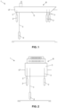
- Figs. 1 and 2 show two views of an exemplary energy storage system (1) installed in a vessel (B).
- the system (1) comprises a plurality of weights (2) hanging from respective cables (3).
- each of the cables (3) hangs from a suitable element arranged inside the hull (C) of the vessel (B) and passes through a respective opening (8) of said hull (C).
- the openings (8) will be cylindrical in shape, the top end of which is located at a higher height than the waterline (LF) of the vessel (B).
- this energy can be utilised to hoist the weights (2) from a lower position up to an upper position, which can be located under the hull (C) of the vessel (B) or above the waterline (LF), passing through the openings, as described below in detail.
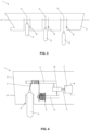
- Fig. 3 shows this exemplary storage system (1) in greater detail.
- the openings (8) in the hull (C) of the vessel (B) have a cylindrical shape the top edge of which is located at a higher height than the waterline (LF) of the vessel (B) to contain the water to prevent this from flooding the inside of the hull (C) of the vessel (B).
- the diameter of the openings (8) is larger than the diameter of the weights (2) such that these can reach up to an upper position through said openings (8) in which at least their upper portion projects above the waterline (LF).
- this is advantageous to facilitate the operation and maintenance tasks of the system of the invention.
- Fig. 4 shows the different elements this exemplary system (1) according to the invention is composed of.
- the cable (3) which the weight (2) hangs from passes through the opening (8) up the first shaft (5), which is a capstan in this example. From the capstan, the cable (3) passes to a spool (4) that rotates around a third shaft (11).
- the first shaft (5) is coupled mechanically to a second shaft (6) by means of a reduction gear (12), and the second shaft (6) is connected to a motor-generator (7) electrically connected to the power grid.
- the mechanical connection between the first shaft (5) and the second shaft (6) is such that the rotation of any of them implies the rotation of the other one.
- the first shaft (5) may be a drive shaft dragging the second shaft (6), or the second shaft (6) may be the drive shaft dragging the first shaft (5).
- the reduction gear (12) comprises a mechanical connection with the third shaft (11), the shaft of the spool (4), to guarantee a suitable synchronisation between said third shaft (11) and the first shaft (5) so that the spool (4) rolls up/down the cable (3) in a coordinated manner with the operation of the capstan.
- the opening (8) has a diameter slightly larger than the weight (2), which is cylindrical too and with rounded edges to reduce the resistance exerted by the water during its vertical displacement between the lower position and the upper position.
- the weight (2) passes through the opening (8) until it projects partially above the sea level corresponding to the waterline (LF) of the vessel (B).
- Fig. 5 shows in greater detail the internal configuration of the cylindrical weight (2) with rounded edges.
- the weight (2) is divided internally into three main parts: a ballast (21), a water reservoir (22) and a compressed-air reservoir (23).
- the ballast (21) is located in the lower portion of the weight (2) and, in this example, it comprises a sand-filled reservoir.
- the compressed-air reservoir (23) is located at the top end of the weight (2) and is presented spherical to better withstand the pressures which it will be subjected to during its shelf life, although it can be cylindrical in shape like a canister.
- the water reservoir (22) is placed between the two preceding reservoirs (21, 23).
- the weight (2) comprises a set of openings (01, 02, O3, O4) arranged in the water reservoir (22) and the compressed-air reservoir (23) to allow water or air to flow into and out of them during the operation of the system (1).
- each of these openings (O1, O2, O3, O4) comprises a suitable valve that allows the opening and closing times to be controlled.
- the openings (01, 02, O3, O4) comprised by the exemplary weight (2) shown in Fig. 5 are described.
- Fig. 6 shows an exemplary valve (V3) for the third opening (O3), which is designed such that it opens and closes when required to operate the system (1) of the invention. Communication means for it to be operated remotely from a control centre are thereby not required.
- the valve (V3) is formed by arms connected to each other such that an angle is formed. At the end of one of the arms, named here upper arm (V3S), there is a float (V31), for example, a cylindrical float. The other arm will be named here lower arm (V3I).
- the connection between both arms (V3S, V3I) is fixed to a rotating connection just above the inner wall of the water reservoir (22).
- valve (V3) when the valve (V3) is so arranged that the lower arm (V3I) is in a vertical position leaning against said inner wall, a sealing element of said lower arm (V3I), not explicitly shown in the figures, closes the opening (O3).
- the valve (V3) rotates up to a position in which the lower arm (V3I) is inclined with respect to the inner wall and is not leaning any more against the same, the opening (O3) is opened, water being allowed to flow into/out of the reservoir (22).
- the system (1) of the invention can be operated without any remotely actuatable valves being required, as described below.
- the starting point is the upper position in which the weight (2) is a similar position to that shown in Fig. 4 (hoisted, on top).
- the water reservoir (22) is filled with water.
- the second opening (O2) is closed. This operation could have been performed manually since the top end of the weight (2) projects above the water.
- the first opening (O1) is closed too. This operation could be manual as well for the same reasons.
- the fourth opening (O4) is closed too since, if a pressure valve is utilised, the pressure inside the water reservoir (22) has not reached the predetermined opening pressure yet.
- the third opening (O3) is open as it is shown in Fig. 6a .
- the float (V31) of the valve (V3) generates a vertical force and upwards causing the valve (V3) to rotate about the articulation in the anticlockwise direction.
- the system (1) is operated such that the weight (2) falls up to the lower position with the objective to utilise the rotation of the first shaft (5) to, through its transmission to the second shaft (6), generate electrical energy by means of the motor-generator (7).
- the valve (V3) is kept open during the entire falling path since the float (V31) keeps on being immersed. Furthermore, due to the fact that the valve (V3) is open, the pressure inside the water reservoir (22) corresponds during the entire fall to the pressure at the depth at which the weight (2) is. As a consequence thereof, the pressure inside the water reservoir (22) increases as the weight (2) falls until, when the weight (2) reaches the lower position, the pressure in the water reservoir (22) reaches the predetermined value at which the valve of the fourth opening (O4) opens.
- the weight (2) is kept in the lower position until there is excess energy in the grid or it is decided to hoist the same utilising the increased buoyancy obtained.
- a suitable blocking means can be utilised to prevent the weight (2) from keeping on falling.
- the motor-generator (7) is actuated as a motor, the rotation of the second shaft (6) causes the first shaft (5) to rotate, and the weight (2) starts to fall from its lower position as the cable (3) is wound on the capstan.
- the third valve (V3) is kept closed since, in addition to this, the pressure of the compressed air inside the water reservoir (22) is higher than the pressure of the water outside the weight (2) at all times. Therefore, the weight rises up to the upper position in which it projects partially above the sea level through the openings (8) in the hull (C) of the vessel (B).
- the water reservoir (22) is refilled with water.
- the valve of the second exhaust opening (O2) is opened.
- the second opening (O2) can be opened either remotely or manually.
- the compressed air inside the water reservoir (22) can be just exhausted to the atmosphere or, alternatively, it can be recovered being led to a compressed-air reservoir arranged in the vessel (B).
- the pressure inside the water reservoir (22) is reduced and, as a consequence thereof, there is a time when the water pushing from the outside causes the valve (V3) to rotate and, consequently, to open, as it is shown in Fig. 6d .
- the water starts to flood the water reservoir (22) until filling it completely.
- a compressed-air duct can be connected to the first opening (O1) manually. Furthermore, it will be necessary to close the exhaust valve of the second opening (O2).
- This operating mode of the energy storage system (1) of the invention can be carried out by utilising weights (2) different in shape.
- weights (2) different in shape.
- the vessel (B) to have large openings (8) in its hull (C) but, at the same time, to make sure that the weight (2) projects in its upper position above the sea level so as to facilitate the operation of the system (1), it is possible to utilise a U-shaped weight (2).
- Fig. 7 shows an exemplary system (1) according to the invention, wherein the weight (2) is U-shaped.
- the U-shaped weight (2) is formed by a horizontal basis from which two vertical arms extend perpendicularly.
- the length of the basis is larger than the beam of the vessel (B) and the length of the arms is larger than the draught of the vessel (B).
- the ends of the arms project above the sea level. This allows the valves of the first and the second opening (01, 02) to be actuated easily, similarly to how it was described above.
- the U-shaped weight (2) hangs from a plurality of cables (3, 10).
- a first subset of cables (3) are arranged similarly to how they are with the cylindrical weights (2) shown in preceding figures. These are cables (3) anchored to the basis of the U-shaped weight (2), which extend through the hull (C) through openings (8) drilled into the same (obviously, these openings (8) will have a top edge above the waterline (LF) of the vessel (B)).
- a second subset of cables (10) hang from cranes or arms protruding from the beam of the vessel (B) and extending vertically in parallel to the gunwale of the vessel (B) until they are connected to the weight (2) at the ends of the arms in the U.
- the connection of all of these cables (3, 10) to the first shaft (5) can be realised in different ways and by employing movement transmission shafts and mechanisms in different configurations.
- Fig. 8 shows in greater detail the internal configuration of the U-shaped weight (2) shown in Fig. 7 .
- the U-shaped weight (2) has three differentiated parts: a ballast (21), located in the lowest part of the basis of the U-shaped weight (2); a water reservoir (22), taking up most part of the volume of both arms of the U-shaped weight (2); and a compressed-air reservoir (23), taking up the part of the top end of the arms of the U-shaped weight (2).
- the operation of these elements is similar to that of the cylindrical weight described above.
- Figs. 9 and 10 show the arrangement of a set of rigid connections (9) between the cables (3, 10) which the weights (2) hang from to prevent them from entangling with one another during the operation of the system (1) of the invention.
- Fig. 9 shows the arrangement of the rigid connections (9) when weights (2) with the shape of a square-section prism are utilised.
- the weight is prismatic with a different cross section such as square, pentagonal, hexagonal or others.
- the references made to the rounded ends of the cylindrical weights (2) should be further understood as applicable to other aerodynamic shapes formed by curved or flat surfaces such as a pyramidal shape.
- the rigid connections (9) are connected to each cable (3) by means of sliding connections along the cable (3) itself. In this manner, the weights (2) can be lifted and lowered independently of one another.
- Fig. 10 shows the rigid connections (9) utilised if several U-shaped weights (2) are utilised, which would be distributed along the length of the vessel (B).
- rigid connections (9) would be utilised not only between pairs of cables (3) connected to the basis of the U but also between pairs of cables (10) connected to the ends of the U.
- the pair of a cable (3, 10) connected to a U-shaped weight (2) is that cable (3) connected in an equivalent position to a contiguous weight (2) arranged in parallel to the first one.
Landscapes
- Engineering & Computer Science (AREA)
- Chemical & Material Sciences (AREA)
- Combustion & Propulsion (AREA)
- Mechanical Engineering (AREA)
- General Engineering & Computer Science (AREA)
- Other Liquid Machine Or Engine Such As Wave Power Use (AREA)
- Memory System Of A Hierarchy Structure (AREA)
Applications Claiming Priority (2)
| Application Number | Priority Date | Filing Date | Title |
|---|---|---|---|
| ES202230154A ES2918019B2 (es) | 2022-02-25 | 2022-02-25 | Sistema de almacenamiento de energía |
| PCT/ES2023/070098 WO2023161549A1 (es) | 2022-02-25 | 2023-02-22 | Sistema de almacenamiento de energia |
Publications (2)
| Publication Number | Publication Date |
|---|---|
| EP4485751A1 true EP4485751A1 (de) | 2025-01-01 |
| EP4485751A4 EP4485751A4 (de) | 2025-12-17 |
Family
ID=82356922
Family Applications (1)
| Application Number | Title | Priority Date | Filing Date |
|---|---|---|---|
| EP23759365.2A Pending EP4485751A4 (de) | 2022-02-25 | 2023-02-22 | Energiespeichersystem |
Country Status (5)
| Country | Link |
|---|---|
| US (1) | US12378942B2 (de) |
| EP (1) | EP4485751A4 (de) |
| ES (1) | ES2918019B2 (de) |
| MX (1) | MX2024009977A (de) |
| WO (1) | WO2023161549A1 (de) |
Families Citing this family (2)
| Publication number | Priority date | Publication date | Assignee | Title |
|---|---|---|---|---|
| US12012923B1 (en) * | 2023-03-07 | 2024-06-18 | Barry Isaac | Power storage system |
| CN120341472A (zh) * | 2025-06-19 | 2025-07-18 | 安兴精密(深圳)有限公司 | 一种储能充电装置 |
Family Cites Families (13)
| Publication number | Priority date | Publication date | Assignee | Title |
|---|---|---|---|---|
| US6933624B2 (en) * | 2003-10-10 | 2005-08-23 | Steven D. Beaston | Hydropower generation apparatus and method |
| US7656051B2 (en) * | 2007-02-05 | 2010-02-02 | James Perin | Buoyancy vehicle apparatus to create electrical power |
| US8166760B2 (en) * | 2008-02-06 | 2012-05-01 | Launchpoint Technologies, Inc. | System and method for storing energy |
| US20160032887A1 (en) * | 2008-02-25 | 2016-02-04 | Roland Wayne Patton | Method and apparatus for converting energy in a moving fluid mass to rotational energy drving a transmission |
| WO2012034104A1 (en) * | 2010-09-10 | 2012-03-15 | Whirl Energy, Inc. | Energy storage devices and methods for using same |
| JP5688764B2 (ja) * | 2011-03-16 | 2015-03-25 | 大洋プラント株式会社 | 水上発電装置 |
| SG11201507439PA (en) * | 2013-03-14 | 2015-10-29 | Mgh S A S | Energy storage system deployed in a body of water |
| WO2016040746A1 (en) * | 2014-09-12 | 2016-03-17 | SeaPower Systems, LLC. | Gravity-based energy-storage system and method |
| BE1023072A1 (fr) * | 2015-04-14 | 2016-11-16 | Louis Stevens | Système de stockage et production d'énergie électrique en milieu marin |
| FR3042548B1 (fr) * | 2015-10-19 | 2017-11-17 | Christophe Stevens | Systeme de stockage et generation d'energie electrique pour milieu aquatique et subaquatique |
| US10605226B2 (en) * | 2018-08-14 | 2020-03-31 | Lone Gull Holdings, Ltd. | Inertial hydrodynamic pump and wave engine |
| GB2596284A (en) * | 2020-06-17 | 2021-12-29 | Energy storage ltd | Aquatic energy storage system and method of use thereof |
| KR102287189B1 (ko) * | 2020-07-16 | 2021-08-06 | 한국에너지기술연구원 | 에너지 발전 및 저장 시스템 |
-
2022
- 2022-02-25 ES ES202230154A patent/ES2918019B2/es active Active
-
2023
- 2023-02-22 WO PCT/ES2023/070098 patent/WO2023161549A1/es not_active Ceased
- 2023-02-22 EP EP23759365.2A patent/EP4485751A4/de active Pending
- 2023-02-22 MX MX2024009977A patent/MX2024009977A/es unknown
- 2023-02-22 US US18/840,555 patent/US12378942B2/en active Active
Also Published As
| Publication number | Publication date |
|---|---|
| MX2024009977A (es) | 2024-09-05 |
| EP4485751A4 (de) | 2025-12-17 |
| US20250154927A1 (en) | 2025-05-15 |
| US12378942B2 (en) | 2025-08-05 |
| ES2918019B2 (es) | 2023-07-25 |
| WO2023161549A1 (es) | 2023-08-31 |
| ES2918019A1 (es) | 2022-07-13 |
Similar Documents
| Publication | Publication Date | Title |
|---|---|---|
| US12378942B2 (en) | Energy storage system | |
| US8125097B1 (en) | Electrical generation using vertical movement of a mass | |
| CN101932830B (zh) | 用于存储能量的系统和方法 | |
| EP2580467B1 (de) | Schwimmendes wasserfahrzeug zur umwandlung von wellenenergie auf see in elektrische energie | |
| EP3273050A1 (de) | Tauchfähige stromerzeugungsplattform | |
| US20160344259A1 (en) | System for storing and generating electric energy for an aquatic medium | |
| JP5216417B2 (ja) | 潮力発電装置 | |
| EP2333311A1 (de) | Struktur zur Nutzung der Gezeitenenergie | |
| NO801530L (no) | Undervannsakkumulator for trykkgass. | |
| KR100389064B1 (ko) | 부력과 중력을 이용한 발전시스템 | |
| EP3464877B1 (de) | Ausgeglichenes wellenleistungswandlersystem | |
| KR20120042828A (ko) | 흐르는 물로부터의 에너지를 이용하기 위해 워터 휠 또는 터빈을 결합하는 잠수형 장치 | |
| GB2550692B (en) | Subsea energy generation assembly utilising wind energy | |
| US20250250958A1 (en) | A buoyant actuator and a wave energy conversion system incorporating a buoyant actuator | |
| EP3269973A1 (de) | System zur extraktion von kraft und kinetischer energie aus meereswellen | |
| WO2023068937A1 (en) | Wave power generator system | |
| NO20240031A1 (no) | Bølgekraftverk 2 | |
| JPH0543920B2 (de) | ||
| IES86095Y1 (en) | A floating vessel that converts wave energy at sea into electrical energy |
Legal Events
| Date | Code | Title | Description |
|---|---|---|---|
| STAA | Information on the status of an ep patent application or granted ep patent |
Free format text: STATUS: THE INTERNATIONAL PUBLICATION HAS BEEN MADE |
|
| PUAI | Public reference made under article 153(3) epc to a published international application that has entered the european phase |
Free format text: ORIGINAL CODE: 0009012 |
|
| STAA | Information on the status of an ep patent application or granted ep patent |
Free format text: STATUS: REQUEST FOR EXAMINATION WAS MADE |
|
| 17P | Request for examination filed |
Effective date: 20240920 |
|
| AK | Designated contracting states |
Kind code of ref document: A1 Designated state(s): AL AT BE BG CH CY CZ DE DK EE ES FI FR GB GR HR HU IE IS IT LI LT LU LV MC ME MK MT NL NO PL PT RO RS SE SI SK SM TR |
|
| DAV | Request for validation of the european patent (deleted) | ||
| DAX | Request for extension of the european patent (deleted) | ||
| A4 | Supplementary search report drawn up and despatched |
Effective date: 20251113 |
|
| RIC1 | Information provided on ipc code assigned before grant |
Ipc: H02J 15/00 20060101AFI20251107BHEP Ipc: F03G 3/02 20060101ALI20251107BHEP Ipc: F03G 3/00 20060101ALI20251107BHEP Ipc: F03B 17/02 20060101ALI20251107BHEP |
|
| RAP1 | Party data changed (applicant data changed or rights of an application transferred) |
Owner name: ENERCOP ALMACENAMIENTO DE RENOVABLES, S.L. |