EP4485199A1 - Zustandsverwaltete asynchrone laufzeit - Google Patents
Zustandsverwaltete asynchrone laufzeit Download PDFInfo
- Publication number
- EP4485199A1 EP4485199A1 EP24180343.6A EP24180343A EP4485199A1 EP 4485199 A1 EP4485199 A1 EP 4485199A1 EP 24180343 A EP24180343 A EP 24180343A EP 4485199 A1 EP4485199 A1 EP 4485199A1
- Authority
- EP
- European Patent Office
- Prior art keywords
- image processing
- cycle
- data
- parallel
- image
- Prior art date
- Legal status (The legal status is an assumption and is not a legal conclusion. Google has not performed a legal analysis and makes no representation as to the accuracy of the status listed.)
- Withdrawn
Links
Images




Classifications
-
- G—PHYSICS
- G06—COMPUTING OR CALCULATING; COUNTING
- G06F—ELECTRIC DIGITAL DATA PROCESSING
- G06F9/00—Arrangements for program control, e.g. control units
- G06F9/06—Arrangements for program control, e.g. control units using stored programs, i.e. using an internal store of processing equipment to receive or retain programs
- G06F9/46—Multiprogramming arrangements
- G06F9/54—Interprogram communication
- G06F9/542—Event management; Broadcasting; Multicasting; Notifications
-
- G—PHYSICS
- G06—COMPUTING OR CALCULATING; COUNTING
- G06F—ELECTRIC DIGITAL DATA PROCESSING
- G06F9/00—Arrangements for program control, e.g. control units
- G06F9/06—Arrangements for program control, e.g. control units using stored programs, i.e. using an internal store of processing equipment to receive or retain programs
- G06F9/30—Arrangements for executing machine instructions, e.g. instruction decode
- G06F9/38—Concurrent instruction execution, e.g. pipeline or look ahead
- G06F9/3867—Concurrent instruction execution, e.g. pipeline or look ahead using instruction pipelines
-
- G—PHYSICS
- G06—COMPUTING OR CALCULATING; COUNTING
- G06F—ELECTRIC DIGITAL DATA PROCESSING
- G06F9/00—Arrangements for program control, e.g. control units
- G06F9/06—Arrangements for program control, e.g. control units using stored programs, i.e. using an internal store of processing equipment to receive or retain programs
- G06F9/46—Multiprogramming arrangements
- G06F9/50—Allocation of resources, e.g. of the central processing unit [CPU]
- G06F9/5005—Allocation of resources, e.g. of the central processing unit [CPU] to service a request
-
- G—PHYSICS
- G06—COMPUTING OR CALCULATING; COUNTING
- G06K—GRAPHICAL DATA READING; PRESENTATION OF DATA; RECORD CARRIERS; HANDLING RECORD CARRIERS
- G06K7/00—Methods or arrangements for sensing record carriers, e.g. for reading patterns
- G06K7/10—Methods or arrangements for sensing record carriers, e.g. for reading patterns by electromagnetic radiation, e.g. optical sensing; by corpuscular radiation
- G06K7/14—Methods or arrangements for sensing record carriers, e.g. for reading patterns by electromagnetic radiation, e.g. optical sensing; by corpuscular radiation using light without selection of wavelength, e.g. sensing reflected white light
- G06K7/1404—Methods for optical code recognition
- G06K7/1408—Methods for optical code recognition the method being specifically adapted for the type of code
- G06K7/1413—1D bar codes
-
- G—PHYSICS
- G06—COMPUTING OR CALCULATING; COUNTING
- G06T—IMAGE DATA PROCESSING OR GENERATION, IN GENERAL
- G06T1/00—General purpose image data processing
- G06T1/20—Processor architectures; Processor configuration, e.g. pipelining
Definitions
- the disclosed embodiments relate generally to electronic circuits and more specifically to systems, devices, and methods for configuring hardware resources to process a plurality of image processing cycles in a plurality of parallel pipelines.
- Computer processors implement parallelism, pipelining, overlap of software tasks, and dedicated hardware acceleration to enhance their processing capabilities. These processing enhancement techniques are often limited to highly repeatable cycles that functionally implement identical or similar jobs involving little or no change from cycle to cycle.
- the computer processors are configured using a register model, and consistently apply a single configuration to drive runtime execution. For example, a processor pipeline oftentimes has a fixed number of stages. Multiple stages are staggered, and a stage of a current cycle oftentimes runs concurrently with a distinct stage of a previous cycle. It would be beneficial to develop a parallel processing mechanism that is highly flexible and efficient while utilizing existing computer resources sufficiently.
- Various embodiments of this application are directed to a core high-performance runtime engine configured to process image data in parallel pipelines for heavy-duty industrial machine vision applications.
- the machine vision applications are applied in an electronic device (e.g., an imaging device including one or more cameras) to implement functions including, but not limited to, image processing, code reading, product information extraction, and print quality verification.
- a state-managed asynchronous pipelined architecture is applied in the electronic device for image processing in these machine vision applications.
- Multiple image processing cycles are executed in parallel in a plurality of pipelines, exploiting hardware capabilities without bottlenecks.
- Each image processing cycle includes a plurality of time-critical stages and operations that are optionally triggered and staggered in a plurality of threads.
- a trigger event is received while a previous image processing cycle is still in progress, and corresponds to a completely different image processing cycle assigned to a different pipeline that is implemented independently of the previous image processing cycle.
- a stage of an image processing job uses available hardware capabilities, and may force any other image processing jobs or other stages of the same image processing job to wait in a queue.
- the state-managed asynchronous pipelined architecture takes advantage of available hardware capabilities and results in an increase in performance by executing multiple image processing cycles in parallel pipelines independently of one another, and this performance increase scales linearly with the number of processor cores of an imaging device.
- an image processing method is implemented at an electronic device (e.g., an imaging device) having memory and one or more processors.
- the method includes identifying a plurality of image processing cycles associated with a temporal sequence of triggers. Each image processing cycle is created in response to one or more respective trigger events.
- the method further includes assigning the plurality of image processing cycles to a plurality of parallel pipelines (e.g., each image processing cycle is assigned to a respective parallel pipeline) and, for each parallel pipeline, pulling a respective cycle data container from a cycle data pool.
- the method further includes processing a first image processing cycle in a first parallel pipeline to generate first report data, independently of processing remaining image processing cycles in respective remaining parallel pipelines.
- the method further includes providing the first report data to a client device, e.g., for further processing (such as storage, classification, analysis, and/or visualization).
- the imaging device is communicatively coupled to the client device (e.g., a laptop computer, a desktop computer, or a mobile phone) via a wired or wireless communication link.
- a user interface of the machine vision application is enabled on the client device to present report data collected from the imaging device in a user friendly manner.
- the client device is located remotely from the imaging device, and coupled to the imaging device via a server.
- a web-based user interface is enabled on the client device to remotely review the report data that is reported by the imaging device by way of the server.
- an electronic device includes one or more processors, memory, and one or more programs stored in the memory.
- the programs are configured for execution by the one or more processors.
- the one or more programs include instructions for performing any of the methods described herein.
- a non-transitory computer-readable storage medium stores one or more programs configured for execution by an electronic device having one or more processors and memory.
- the one or more programs include instructions for performing any of the methods described herein.
- a state-managed asynchronous pipelined architecture is applied in an electronic device (e.g., an imaging device) for image processing in these machine vision applications.
- the electronic device identifies a plurality of image processing cycles associated with a temporal sequence of triggers, and each image processing cycle is created in response to one or more respective trigger events (e.g., acquisition of an image).
- the electronic device assigns the plurality of image processing cycles to a plurality of parallel pipelines. For each parallel pipeline, a pre-existing cycle data container is pulled from a cycle data pool.
- a first image processing cycle is processed in a first parallel pipeline to generate first report data, independently of remaining image processing cycles in respective remaining parallel pipelines.
- the first report data is provided to a client device.
- each image processing cycle includes a plurality of time-critical operations and stages that are optionally triggered and staggered in a plurality of threads of a corresponding pipeline.
- Such a state-managed asynchronous pipelined architecture takes advantage of available hardware capabilities and results in a substantial increase in performance by executing multiple image processing cycles in parallel pipelines independently, and this performance increase scales linearly with a number of processor cores (e.g., CPUs, FPGAs, NPUs, and/or GPUs) of the electronic device.
- the primary objective of the state-managed asynchronous pipelined architecture is to achieve maximum performance for an image processing system for full utilization of hardware resources including, but not limited to, processors, acquisition sources, input/output, communication channels, processing threads, and processes. Additionally, this architecture greatly simplifies user intervention to control, configure and monitor a runtime, thereby enhancing user experience.
- the processing pipelines and associated hardware and software settings are altered at any time without creating a significant overhead.
- self-analysis and tuning of the architecture is automatically enabled by deep instrumentation to improve image processing performance with no or little user interaction.
- FIG. 1 is a perspective view of an electronic device 100 (e.g., a scanning device), in accordance with some embodiments.
- the electronic device 100 is also referred to as a code reader, a barcode scanner, a label scanner, an optical scanner, or an image capturing system.
- the electronic device 100 is part of an optical data reading system (e.g., a label scanning station).
- the electronic device 100 includes a housing 110 (e.g., a body or an exterior case) for protecting components that are located inside the electronic device 100.
- the housing 110 includes integrated fittings or brackets to keep the internal components in place.
- the electronic device 100 includes a top cover 102 positioned on the top side of the electronic device 100. In some embodiments, the top cover 102 is transparent or partially transparent.
- each distance sensor 104 is a time-of-flight (TOF) sensor, an ultrasonic sensor, a radar sensor, a light detection and ranging (LiDAR) sensor, or an infrared (IR) distance sensor.
- the electronic device 100 includes two or more distance sensors 104, each having the same type (e.g., each of the two or more distance sensors is a TOF sensor).
- the electronic device 100 includes two or more distance sensors, at least two of which are of distinct types (e.g., the electronic device 100 includes a TOF distance sensor and a radar sensor).
- the electronic device 100 includes one or more proximity sensors for sensing (e.g., detecting) if an object is within the sensing area where the proximity sensor is designed to operate.
- the electronic device 100 uses distance measuring techniques, such as an image focus finder, an analog-to-digital conversion (ADC) circuit, and/or a digital-to-analog conversion (DAC) circuit, to determine the distance between a target object and the electronic device 100.
- ADC analog-to-digital conversion
- DAC digital-to-analog conversion
- the distance sensor 104 is a TOF sensor.
- a TOF sensor measures the elapsed time from the emission of a signal (e.g., a wave pulse, an LED pulse, a laser pulse, or IR waves) from the sensor to the moment it returns to the sensor after reflecting off of an object. Distance is then calculated by using the speed of light in air and the time between sending/receiving the signal.
- the distance sensor 104 is an ultrasonic sensor.
- An ultrasonic sensor, or a Sonar sensor detects the distance to an object by emitting high-frequency sound waves. The ultrasonic sensor emits high-frequency sound waves towards a target object, and a timer is started. The target object reflects the sound waves back towards the sensor.
- the distance sensor 104 is a radar sensor.
- the radar sensor e.g., a radar distance sensor
- transmits high frequency radio waves e.g., microwaves
- the radar sensor is configured to determine the distance, the angle, and the radial velocity of an object relative to the location of the electronic device 100.
- the distance sensor 104 is a LiDAR sensor, which measures the range of a target object through light waves from a laser (e.g., instead of radio or sound waves).
- the distance sensor 104 is an infrared (IR) distance sensor. An IR distance sensor works through the principle of triangulation, measuring distance based on the angle of the reflected beam.
- the electronic device 100 further includes a plurality of light sources 106 (e.g., 8 light emitting diodes (LEDs) in Figure 1 ) mounted on a printed circuit board (PCB) 108.
- a light source 106 is also called a lighting source, an illumination source, or an illuminator.
- the light sources 106 are part of an illumination system of the electronic device 100, which also includes illuminators (e.g., bright field and dark field illuminators), a reflector, and a lighting module. More details on the illumination system are described in U.S. Patent Application No. 14/298,659, filed June 6, 2014 , entitled “Combination Dark Field and Bright Field Illuminator," now U.S. Patent No. 8,989,569, issued on March 24, 2015 , which is incorporated by reference herein in its entirety.
- the light sources 106 have one or more lighting types. Examples of the lighting types include, but are not limited to, LED light sources, laser light sources, and liquid crystal display (LCD) lights. Each of the lighting types has respective lighting characteristics, such as color (e.g., blue, red, or green) and/or intensity.
- the light sources 106 are mounted on (e.g., soldered on) the PCB 108, which is positioned within the electronic device 100 (e.g., behind the top cover 102).
- the PCB 108 includes a front surface facing the top cover 102 of the electronic device 100.
- the light sources mounted on the front surface of the PCB 108 includes both long range light sources and low angle light sources.
- the electronic device 100 includes a camera 112.
- a lens of the camera 112 is exposed via an opening of the PCB 108 and physically surrounded by the light sources 106.
- the light sources 106 are grouped into a plurality of illumination units (e.g., a first illumination unit and a second illumination unit).
- Each illumination unit is configured to be independently controlled to illuminate a distinct region of the field of view of the camera 112.
- every two light sources 106 near a corner of the top cover 102 are grouped to form an illumination unit.
- Four illumination units are independently controlled to illuminate respective regions of a field of view of the camera 112 in a sequential or concurrent manner.
- the electronic device 100 further includes one or more indicators 114.
- Each indicator 114 is located at an edge of the top cover 102 of the electronic device 100, and configured to be illuminated according to a light pattern in which a single color or different colors are displayed for a sequence of temporal durations defined based on the frequency.
- the light pattern represents a message including data or status of the electronic device 100.
- the indicators 114 are illuminated with a red color continuously in response to detection of the presence of a product on or near the top cover, and turn to a green color and stay in green for a shortened duration of time in response to a successful scan of a barcode displayed on the product.
- each indicator 114 includes one or more LEDs from which light is emitted, and the light is displayed on the indicator 114 in a substantially uniform and homogeneous manner.
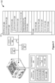
- FIG. 2 is a block diagram of an example electronic device 100, in accordance with some embodiments.
- the electronic device 100 includes one or more distance sensors 104, as described previously with respect to Figure 1 .
- the one or more distance sensors 104 include one or more of: a time-of-flight sensor, an ultrasonic sensor, a radar sensor, or a LiDAR sensor.
- the electronic device 100 includes one or more proximity sensors for sensing (e.g., detecting) if an object is within the sensing area where the proximity sensor is designed to operate.
- the electronic device 100 uses distance measuring techniques, such as an image focus finder, analog-to-digital conversion (ADC), and/or digital-to-analog conversion (DAC), to determine the distance between a target object and the electronic device 100.
- ADC analog-to-digital conversion
- DAC digital-to-analog conversion
- the electronic device 100 includes one or more input interfaces 210 for facilitating user input.
- the electronic device 100 is a battery-operated device and includes a rechargeable battery.
- the input interface 210 can include a charging port for charging the battery.
- the electronic device 100 includes a camera 112, which includes an image sensor 216 and a lens 218.
- the lens 218 directs the path of light rays and concentrates them onto the image sensor 216, to re-create the image as accurately as possible on the image sensor.
- the image sensor 216 converts light (e.g., photons) into electrical signals that can be interpreted by the electronic device 100.
- the lens 218 is an optical lens and is made from glass or other transparent material.
- the lens 218 is a liquid lens that is composed of an optical liquid material, and whose shape, focal length, and/or working distance varies when a current or voltage is applied to the liquid lens.
- the electronic device 100 also includes one or more processors (e.g., CPU(s)) 202, one or more communication interface(s) 204 (e.g., network interface(s)), memory 206, and one or more communication buses 208 for interconnecting these components (sometimes called a chipset).
- processors e.g., CPU(s)
- communication interface(s) 204 e.g., network interface(s)
- memory 206 e.g., volatile and non-volatile memory
- communication buses 208 for interconnecting these components (sometimes called a chipset).
- the electronic device 100 includes radios 220.
- the radios 220 enable one or more communication networks, and allow the electronic device 100 to communicate with other devices, such as a computer device or a server.
- the radios 220 are capable of data communication using any of a variety of custom or standard wireless protocols (e.g., IEEE 802.15.4, Wi-Fi, ZigBee, 6LoWPAN, Thread, Z-Wave, Bluetooth Smart, ISA100.5A, WirelessHART, MiWi, Ultrawide Band (UWB), and/or software defined radio (SDR)), custom or standard wired protocols (e.g., Ethernet or HomePlug), and/or any other suitable communication protocol, including communication protocols not yet developed as of the filing date of this patent application.
- custom or standard wireless protocols e.g., IEEE 802.15.4, Wi-Fi, ZigBee, 6LoWPAN, Thread, Z-Wave, Bluetooth Smart, ISA100.5A, WirelessHART, MiWi, Ultrawide Band (UWB), and/
- the memory 206 includes high-speed random access memory, such as DRAM, SRAM, DDR RAM, or other random access solid state memory devices.
- the memory includes non-volatile memory, such as one or more magnetic disk storage devices, one or more optical disk storage devices, one or more flash memory devices, or one or more other non-volatile solid state storage devices.
- the memory 206 includes one or more storage devices remotely located from one or more processor(s) 202.
- the memory 206, or alternatively the non-volatile memory within the memory 206 includes a non-transitory computer-readable storage medium.
- the memory 206, or the non-transitory computer-readable storage medium of the memory 206 stores the following programs, modules, and data structures, or a subset or superset thereof:
- the distance sensor 104 is monitored by the lighting module 232.
- the distance sensor 104 identifies a distance field (e.g., near field, medium field, or far field) corresponding to the location of the target object.
- the lighting module 232 selects a lighting sequence, corresponding to the distance field, for execution.
- a good read was achieved in a previous read cycle (e.g., a good read from the third lighting pattern of the near field lighting sequence), and the current read cycle has the same distance field as the previous read cycle
- the application 230 will commence the current read cycle by using values of the earlier good read (e.g., the third lighting pattern of the near field lighting pattern, the previous focus position, the exposure, and/or the gain), before starting the lighting sequence from the beginning. Users are typically reading many similar parts, and the apparatus can achieve a good read sooner if it starts with known good settings from the last decode operation. If no previous settings lead to a good read, then the lighting sequence for the current distance field starts at the beginning and iterates through each sequence capture-after-capture.
- the exposure and gain module 238 rejects images that do not fall within predefined attribute ranges for "brightness” and/or “sharpness” (e.g., the rejected images are not processed by the image acquisition and processing module 240). In some embodiments, the exposure and gain module 238 updates image acquisition settings (such as exposure and gain) for the next coming image capture in order to provide the optimal "brightness" for image processing.
- the electronic device 100 evaluates the quality of an acquired image. For example, the electronic device 100 reads (e.g., determines) a sharpness value, an average light mean value, and/or an average dark mean value of the image, to determine whether to qualify or reject the image. If the results do not meet or exceed predefined target values, the image is rejected and another image is recaptured. If the results meet or exceed the predefined target values, the image is processed (e.g., by the image acquisition and processing module 240).
- a good quality image is an image sample that has a light mean score between 100 - 170 (out of the range of 0 to 255), a dark mean score between 20 - 80 (out of the range of 0 to 255), and a sharpness score above 6000 (out of the range from 0 to about 12,000).
- data collected during the image sampling (e.g., evaluation) is captured and added (e.g., as data 242).
- the electronic device 100 determines whether to adjust the exposure or gain setting (e.g., using a light mean correction path or a dark mean correction path) for the next image. Should it decide to do so, the electronic device 100 gathers the target light mean and dark mean values for comparison, deploys a Proportional and Integral (PI) Controller transfer function, and computes necessary changes to exposure in order to obtain an ideal exposure in the next image.
- PI Proportional and Integral
- the exposure, gain, and focus values are fed back to the application 230.
- the application 230 checks if these decode settings are pending. If they are, the electronic device 100 attempts to load camera settings and any previous settings, as opposed to calculating the next configuration of settings. Should the previous decode settings be used, the application 230 samples the image for data but does not adjust the feedback controller's values.
- Each of the above identified executable modules, applications, or sets of procedures may be stored in one or more of the previously mentioned memory devices, and corresponds to a set of instructions for performing a function described above.
- the above identified modules or programs i.e., sets of instructions
- the memory 206 stores a subset of the modules and data structures identified above.
- the memory 206 may store additional modules or data structures not described above.
- a subset of the programs, modules, and/or data stored in the memory 206 are stored on and/or executed by a server system, and/or by an external device (e.g., a computing device).
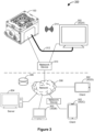
- Figure 3 is an example image processing environment 300 including an electronic device 100 that processes images data using parallel pipelines, in accordance with some embodiments.
- the electronic device 100 is an imaging device.
- the electronic device 100 is a code reader, a barcode scanner, a label scanner, or an optical scanner.
- the electronic device 100 is part of an optical data reading system (e.g., a label scanning station).
- the electronic device 100 is configured to obtain image data including one or more images, process the image data using the parallel pipelines, and provide report data 312 generated from the image data to one or more client devices 302 (e.g., devices 302A, 302B, 302C, or 302D).
- client devices 302 e.g., devices 302A, 302B, 302C, or 302D.
- the one or more client devices 302 may be, for example, desktop computers, tablet computers, mobile phones, or intelligent, multi-sensing, network-connected home devices (e.g., a display assistant device). Each client device 302 can collect the report data 312 from the electronic device 100, receive user inputs, execute user applications, and present the report data 312 or other information on its user interface.
- a user application includes an interactive user application. A user interface of the interactive user application is displayed on the client device to receive the user inputs associated with the electronic device 100 and visualize the report data 312 generated by the electronic device 100.
- the electronic device 100 is configured to enable a plurality of parallel pipelines.
- the electronic device 100 identifies a plurality of image processing cycles associated with a temporal sequence of triggers, and each image processing cycle is created in response to one or more respective trigger events (e.g., one or more image capturing operations).
- the plurality of image processing cycles is assigned to a plurality of parallel pipelines.
- a pre-existing cycle data container is directly pulled from a cycle data pool for each parallel pipeline.
- the electronic device processes the plurality of image processing cycles in the plurality of parallel pipelines to generate respective report data independently of one another.
- the temporal sequence of triggers correspond to an ordered sequence of images that is processed during the image processing cycles.
- the report data 312 of the image processing cycles is generated separately from the plurality of parallel pipelines, independently of the order of the sequence of images. In some situations, the report data of the image processing cycles is organized and provided to the client device 302 according to the order of the corresponding sequence of images.
- the user application implemented on the client device 302 is driven by a first programming language, and the plurality of image processing cycles are executed on the electronic device 100 by a second programming language distinct from the first programming language.
- the plurality of image processing cycles is configured to exchange instructions and data with the user application automatically via an intermediate data representation between the first and second programming languages.
- the intermediate data representation is implemented in JSON (JavaScript Object Notation).
- the user application includes a web-based user interface, and the first programming language includes JavaScript.
- a runtime associated with the image processing cycles uses the second language (e.g., C++).
- JSON is a native format for the runtime by building JSON support into nearly every runtime C++ object, thereby allowing the JavaScript program to understand a workflow format or a report format that is used by the runtime automatically.
- the report data 312 or user inputs are processed locally at the client device 302 and/or remotely by the server(s) 304.
- the one or more servers 304 provide system data (e.g., boot files, operating system images, and user applications) to the client devices 302, and in some embodiments, process the report data 312 and user inputs received from the client device(s) 302 when the user application is executed on the client devices 302.
- the data processing environment 300 further includes a storage device 306 for storing data related to the servers 304, client devices 302, electronic device 100, and user applications executed on the client devices 302.
- the storage device 306 may store video content, static visual content, and a product database.
- the one or more servers 304, the one or more client devices 302, the electronic device 100, and the storage device 306 are communicatively coupled to each other via one or more communication networks 308, which are the medium used to provide communications links between these devices and computers connected together within the data processing environment 300.
- the one or more communication networks 308 may include connections, such as wire, wireless communication links, or fiber optic cables. Examples of the one or more communication networks 308 include local area networks (LAN), wide area networks (WAN) such as the Internet, or a combination thereof.
- the one or more communication networks 308 are, optionally, implemented using any known network protocol, including various wired or wireless protocols, such as Ethernet, Universal Serial Bus (USB), FIREWIRE, Long Term Evolution (LTE), Global System for Mobile Communications (GSM), Enhanced Data GSM Environment (EDGE), code division multiple access (CDMA), time division multiple access (TDMA), Bluetooth, Wi-Fi, voice over Internet Protocol (VoIP), Wi-MAX, or any other suitable communication protocol.
- USB Universal Serial Bus
- FIREWIRE Long Term Evolution
- LTE Long Term Evolution
- LTE Long Term Evolution
- GSM Global System for Mobile Communications
- EDGE Enhanced Data GSM Environment
- CDMA code division multiple access
- TDMA time division multiple access
- Bluetooth Wi-Fi
- Wi-Fi voice over Internet Protocol
- Wi-MAX wireless wide area network
- a connection to the one or more communication networks 308 may be established either directly (e.g., using 3G/4G connectivity to a wireless carrier), or through a network interface 310 (e.g., a router, a switch, a gateway, a hub, or an intelligent, dedicated whole-home control node), or through any combination thereof.
- the one or more communication networks 308 can represent the Internet of a worldwide collection of networks and gateways that use the Transmission Control Protocol/Intemet Protocol (TCP/IP) suite of protocols to communicate with one another.
- TCP/IP Transmission Control Protocol/Intemet Protocol
- At the heart of the Internet is a backbone of high-speed data communication lines between major nodes or host computers, consisting of thousands of commercial, governmental, educational and other electronic systems that route data and messages.
- the electronic device 100 is communicatively coupled to the client device 302 (302A) via a wired communication link 312. In some embodiments, the electronic device 100 is communicatively coupled to the client device 302 (302A) via a local communication network 314 enabled by the network interface 310. Both the electronic device 100 and client device 302 (e.g., 302A) are located in the same venue (e.g., a warehouse or a factory). In some embodiments, the electronic device 100 is remote from the client device 302, and communicatively coupled to the client device 302 (e.g., devices 302B, 302C, and/or 302D) via at least a WAN.
- the client device 302 e.g., devices 302B, 302C, and/or 302D
- FIG. 4 illustrates a process 400 of processing image data in a plurality of parallel pipelines 402 (e.g., 402A, 402B, and 402C), in accordance with some embodiments.
- the process 400 is implemented by an electronic device 100 having memory 206 and one or more processors 202.
- the process 400 is executed by the processors 202 according to instructions provided by an image acquisition and processing module 240 of the electronic device 100.
- the electronic device 100 identifies a plurality of image processing cycles 404 associated with a temporal sequence of triggers (e.g., acquisitions of images).
- Each image processing cycle 404 (e.g., 404A, 404B, and 404C) is created in response to one or more respective trigger events (e.g., capturing a single image or capturing a set of images).
- the plurality of image processing cycles 404 is assigned to a plurality of parallel pipelines 402.
- a pre-existing cycle data container 406 (e.g., 406A) is pulled from a cycle data pool 408.
- the cycle data pool 408 includes a predefined number of cycle data containers 406 prior to identifying the plurality of image processing cycles 404.
- each parallel pipeline 402 directly uses one of the predefined number of cycle data containers 406 without waiting for creation of a new cycle data container 406. This expedites initiation and execution of each parallel pipeline 402. In some situations, the cycle data containers 406 have been fully used with different pipelines 402, and no cycle data container 406 can be pulled for a pipeline 402 assigned with a new image processing cycle 404.
- the plurality of image processing cycles 404 is assigned to the plurality of parallel pipelines 402, the plurality of image processing cycles 404 is processed in the plurality of parallel pipelines 402 independently of one another, thereby generating report data 312 (e.g., 312A, 312B, and 312C) independently.
- the report data 312 is provided to a client device 302 for further processing (e.g., storage, classification, analysis, and/or visualization).
- the client device 302 is coupled to the electronic device 100 via a local communication network, and executes an interactive user application 412.
- the client device 302 and the electronic device 100 are located in a factory automation network that has no access to the Internet.
- the interactive user application 412 includes a user interface configured to configure, adjust, and debug the electronic device 100 and its associated workflows and jobs locally.
- the interactive user application 412 is web-based and implemented on the client device 302, which is coupled to a WAN (e.g., the Internet).
- a web-based user interface is enabled in a browser-based user application 412.
- the browser-based user application 412 is served directly from the client device 302, and communicates with the electronic device 100 using HTTP and web sockets.
- a web-based user interface is presented to allow the client device 302 to configure, adjust, and debug the electronic device 100 and its associated workflows and jobs remotely.
- the process 400 enables highly interactive browser based user experience by exchanging data structures between the web-based user interface of the user application 412 and the runtime of the plurality of parallel pipelines 402.
- the user application 412 is implemented based on Hypertext Transfer Protocol (HTTP), and the client device 302 executing the user application 412 includes an Internet of Things (IOT) device.
- IOT Internet of Things
- configuration of the user application 412 and the pipelines 402 is done via a data exchange scheme using JavaScript Object Notation (JSON), allowing a JavaScript driven web-based user interface to interact natively with a core runtime implemented in C++ or other non-dynamic computer languages.
- JSON JavaScript Object Notation
- Second report data 312B of the second image processing cycle 404B is provided to the client device 302 after first report data 312A of the first image processing cycle 404A, independently of whether the second report data 312B is available before or after the first report data 312A.
- independently of the temporal order of the first and second trigger events, whichever one of the first and second report data 312A and 312B is first available is reported to the client device 302 first.
- the second report data 312B of the second image processing cycle 404B is available before the first report data 312A of the first image processing cycle 404A, the second report data 312B is provided to the client device 302 before the first report data 312A. If the second report data 312B is available after the first report data 312A, the second report data 312B is provided to the client device 302 after the first report data 312A.
- First cycle data 414A includes image data associated with one or more respective trigger events of the first image processing cycle 404A and intermediate data that is generated by, and passed among, a plurality of stages of the first image processing cycle 404A.
- the first cycle data 414A includes first report data 312A generated from the intermediate data and reported to the client device 302.
- all of the image data, intermediate data, and report data of the first image processing cycle 404A is reported to the client device 302.
- only the report data 312A of the first image processing cycle 404A is reported to the client device 302.
- the electronic device 100 is configured to recognize a bar code in an image.
- a first image processing cycle 404A is created in response to a first trigger event 602 in which an image including a bar code is captured.
- the first cycle data 414 associated with the first image processing cycle 404 includes a serial number corresponding to the bar code.
- First report data 312A generated from the first image processing cycle 404 includes a product name and a price of a product.
- each pipeline has fixed stages, which are staggered so that a first stage of a current cycle runs concurrently with a second stage of a previous cycle that precedes the current cycle.
- the parallel pipelines 402 have no such limitation, and each parallel pipeline 402 is switched on for a corresponding image processing cycle 404 without any overhead.
- Each cycle's stages are run within the same pipeline 402, while the pipeline 402 includes a managed number of threads and is associated with a cycle data container 406 pulled from a cycle data pool 408.
- FIG 5 illustrates another example process 500 of processing image data in a plurality of parallel pipelines 402, in accordance with some embodiments.
- the process 500 is implemented by an electronic device 100 having memory 206 and one or more processors 202 ( Figure 2 ).
- the process 500 is executed by the processors 202 according to instructions provided by an image acquisition and processing module 240 of the electronic device 100.
- the electronic device 100 provides acquisition service 502, which identifies a plurality of image processing cycles 404 associated with a temporal sequence of triggers (e.g., acquisitions of images).
- Each image processing cycle 404 e.g., 404A, 404B, and 404C
- Each image processing cycle 404 is created in response to one or more respective trigger events (e.g., capturing a single image, capturing a set of images).
- the plurality of image processing cycles is arranged in a runnable cycle queue 504.
- the plurality of image processing cycles 404 is assigned to a plurality of parallel pipelines 402.
- a pre-existing cycle data container 406 e.g., 406A
- Cycle data 414 is associated with, or generated for, each image processing cycle 404 and stored in the corresponding cycle data container 406 during the course of managing and executing the image processing cycle 404.
- a first image processing cycle 404A is implemented in a first parallel pipeline 402A to inspect an input image, e.g., to detect smearing of a label on a drug bottle.
- the first image processing cycle 404A includes a plurality of stages, e.g., an inspection stage 506, a post inspection stage 508, a report generation stage 510, and a data returning stage 512.
- the input image is inspected in the inspection stage 506 and generated intermediate data stored with the cycle data 414 in the cycle data container 406A.
- the intermediate data is further processed in the post inspection stage 508 to provide additional information, which is used to generate first report data 312A in the report generation stage 510.
- the first report data 312A is placed in a queue of pending data 514 to be provided to the client device 302 in the data returning stage 512.
- report data 312 is organized in the queue of pending data 514 based on a temporal order of associated trigger events.
- report data 312 is organized in the queue of pending data 514 based on a temporal order of its own availability, independently of the temporal order of associated trigger events.
- Each stage of an image processing cycle 404A is not limited by fixed hardware allocation, and has a flexible access to hardware resources allocated to a corresponding parallel pipeline 402A. Stated another way, each stage of the image processing cycle 404A can be either accelerated using all of the allocated pipeline hardware resources or executed in parallel with one or more remaining stages of the image processing cycle 404A.
- the plurality of image processing cycles 404 that is assigned to the plurality of pipelines 402 includes a plurality of first image processing cycles 404-1.
- the runnable cycle queue 504 further includes a plurality of second image processing cycles 404-2 following the first image processing cycles 404-1.
- a state signal 516 e.g., "wait for idle" is sent to the runnable cycle queue 504, requesting that the runnable cycle queue 504 hold the plurality of second image processing cycles 404-2 until the plurality of pipelines 402 completes processing of the plurality of first image processing cycles 404-1.
- the electronic device 100 while processing the plurality of first image processing cycles 404-1 in the plurality of parallel pipelines 402, the electronic device 100 dynamically adjusts one or more parameters of: a number of pipelines, a size of thread pools, thread priorities, delays, throttling parameters, core assignments, acquisition parameters, lighting , and camera focus.
- the plurality of second image processing cycles 404-2 is assigned to the plurality of parallel pipelines 402, and processed in the parallel pipelines 402 based on the one or more adjusted parameters.
- the electronic device 100 monitors central processing unit (CPU) core utilization. Based on the CPU core utilization, the electronic device 100 dynamically adjusts respective computational resources allocated to the plurality of parallel pipelines.
- CPU central processing unit
- the electronic device 100 dynamically adjusts respective computational resources allocated to the plurality of parallel pipelines.
- parameters that control limits on hardware use e.g., CPU core utilization
- CPU core utilization parameters that control limits on hardware use
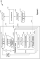
- FIG 6 illustrates another example process 600 of processing image data in a plurality of parallel pipelines 402, in accordance with some embodiments.
- the process 600 is implemented by an electronic device 100 having memory 206 and one or more processors 202 ( Figure 2 ).
- the process 600 is executed by the processors 202 according to instructions provided by an image acquisition and processing module 240 of the electronic device 100.
- the electronic device 100 provides acquisition service 502, which identifies a plurality of image processing cycles 404 associated with a temporal sequence of triggers 602 (e.g., acquisitions of images) in an engine queue thread 604.
- Each image processing cycle 404 (e.g., 404A, 404B, and 404C) is created in response to one or more respective trigger events 602 (e.g., capturing a single image, capturing a set of images).
- the electronic device 100 further includes configuration service 606, which provides job configurations applied to define (operation 608) the image processing cycles 404 to process the image data captured by the temporal sequence of triggers 602. Based on a temporal order of the triggers 602, the plurality of image processing cycles 404 is arranged in a runnable cycle queue 504. The plurality of image processing cycles 404 is assigned to a plurality of parallel pipelines 402.
- Cycle data 414 is associated with, or generated for, each image processing cycle 404 and stored in the corresponding cycle data container 406 during the course of managing and executing the image processing cycle 404.
- a trigger event 602 includes acquisition of a single image, and the single image is processed in a corresponding image processing cycle 404.
- the single image is optionally processed via a plurality of stages 610 (e.g., 610A and 610B) that are managed in a single thread 612 or a plurality of threads 612 of the image processing cycle 404.
- a first stage 610A is implemented at least partially in parallel with a second stage 610B.
- a plurality of trigger events 602 includes acquisition of a plurality of images.
- an image processing cycle 404 is executed to process the plurality of images associated with the plurality of trigger events 602 in a plurality of stages 610.
- the plurality of stages 610 is optionally processed by a single thread 612 or a plurality of threads 612 of the image processing cycle 404.
- One of the plurality of images is optionally processed via a plurality of stages that are managed in an associated single thread 612 or a subset of the plurality of threads 612 of the image processing cycle 404.
- a stage 610B of image processing is implemented a subset of parallel threads 612.
- the electronic device 100 successively implements each of a sequence of stages of an image processing cycle 404 using all or part of first hardware resources allocated to a corresponding parallel pipeline 402.
- a corresponding cycle data container 406 is populated with the plurality of images provided to the parallel pipeline 402.
- the cycle data container 406 optionally stores raw image data of the plurality of images or pre-processed image data of the plurality of images (e.g., filtered images, corrected images, associated image features).
- an image signal processor ISP is configured to filter or correct the raw image data captured by a camera.
- Each image processing cycle 404 is configured to process the raw or pre-processed image data.
- a first image processing cycle 404 includes a first thread 612A and a second thread 612B.
- the second thread 612B optionally starts before or after the first thread 612.
- the first thread 612A generates a first subset of the first cycle data 414.
- the second thread 612B is initiated before generation of the first subset of the first cycle data 414, and suspended to wait until the first subset of the first cycle data 414 is generated and provided by the first thread 612A.
- a workflow template is loaded on the first parallel pipeline 402A.
- the plurality of stages 610 of the first image processing cycle 404A is implemented without being interrupted by the remaining image processing cycles (e.g., 402B and 402C in Figure 4 ).
- a plurality of stages 610 of a distinct image processing cycle 404 may be implemented in a second parallel pipeline 402B using an identical or different workflow template. There is no overhead to switch between workflow templates while implementing these two image processing cycles separately in two pipelines 402.
- the plurality of stages 610 of an image processing cycle 404 is forced to follow a temporal sequencing with a previous image processing cycle. This makes certain operations (e.g. sending result data) happen in sequence between cycles.
- both of the image processing cycles 404A and 404B are processed by the first parallel pipeline 402A, and the second image processing cycle 404B follows the first image processing cycle 404A.
- the stages 610 of the second image processing cycle 402B is forced to follow a temporal sequencing with the first image processing cycle 402A.
- First report data 312A generated by the first image processing cycle 402A is optionally used by the second image processing cycle 402B.
- the electronic device 100 includes a state managed asynchronous runtime engine 614 configured to keep a runtime in a known state. Instead of individual commands to change parameters or having to set a mode to perform an operation, the state of the runtime is always coherent, and can only be changed to a new state (or not if the new state is not accepted). This eliminates much of the complication of managing user experience (for example, undo is trivial).
- the state used by an image processing cycle 404 is included in cycle data 414 stored in the cycle data container 406.
- the cycle data 414 flows through the stages and operations of the image processing cycle 404 implemented in the parallel pipeline 402.
- Application of the cycle data in the cycle data container 406 maximizes parallelism with other services, such as image acquisition.
- the cycle data container 406 contains all the information needed to complete the objective for the corresponding image processing cycle 404, and can be completely swapped for a new objective on the next image processing cycle 404.
- the cycle data 414 further includes input queues for data that is obtained or generated during execution of a parallel pipeline 402. For example, acquisition of images is optionally overlapped with other processing, and the images are pushed to a queue within the cycle data 414, when a stage 610 needs the image data and there is a potential to block if the data has not arrived yet.
- FIG. 7 is a temporal diagram 700 of a plurality of image processing cycles 404 implemented in a plurality of parallel pipelines 402, in accordance with some embodiments.
- Each of the plurality of image processing cycles 404 is processed in a respective parallel pipeline 402, independently of remaining image processing cycles in respective remaining parallel pipelines.
- Figure 8 is a flow diagram of a method 800 for processing image data, in accordance with some embodiments.
- the method is implemented by an electronic device 100, particularly by an image acquisition and processing module 240 of the electronic device 100.
- the electronic device 100 includes one or more cameras 112 configured to capture images.
- the electronic device 100 is coupled to a camera or a distinct electronic device having a camera, and configured to acquire image data including a sequence of images.
- the electronic device 100 identifies (802) a plurality of image processing cycles 404 associated with a temporal sequence of triggers 602. Each image processing cycle 404 is created in response to one or more respective trigger events. Each trigger event includes acquisition of a respective image.
- the electronic device 100 assigns (804) the plurality of image processing cycles 404 to a plurality of parallel pipelines 402. For each parallel pipeline 402, a respective cycle data container 406 is pulled (806) from a cycle data pool 408.
- the electronic device 100 processes (808) a first image processing cycle 404A in a first parallel pipeline 402A to generate first report data, independently of processing remaining image processing cycles 404 (e.g., 404B and 404C in Figure 4 ) in respective remaining parallel pipelines 402.
- the first report data is provided (810) to a client device 302 (e.g., 302A in Figure 3 ), e.g., for display on a web-based user interface of the client device 302.
- a trigger event includes acquisition of a single image, and the single image is processed in a corresponding image processing cycle 404.
- a plurality of trigger events includes acquisition of a plurality of images, and in response to the plurality of trigger events, an image processing cycle 404 is executed to process the plurality of images associated with the plurality of trigger events.
- the plurality of trigger events is processed by a plurality of threads.
- a first thread 612A ( Figure 6 ) generates a first subset of first cycle data 414A to be applied by a second thread 612. The second thread 612 is initiated, and suspended to wait until the first subset of the first cycle data 414A is generated and made available by the first thread.
- the cycle data pool 408 includes a predefined number of cycle data containers 406 prior to identifying the plurality of image processing cycles 404.
- each parallel pipeline 402 Once assigned to a respective image processing cycle 404, each parallel pipeline 402 directly uses one of the predefined number of cycle data containers 406 without waiting for creation of the cycle data container 406. This expedites initiation and execution of each parallel pipeline 402. In some situations, the predefined number of cycle data containers is fully used with different pipelines 402, and no cycle data container 406 can be pulled for a pipeline 402 assigned with a new image processing cycle 404.
- processing the first image processing cycle 404A further includes populating (812) a first cycle data container 406A with image data associated with the one or more respective trigger events associated with the first image processing cycle 404A, generating (814) first cycle data 414A including the first report data 312A, and storing (816) the first cycle data 414A in the first cycle data container 406A.
- data stored in the first cycle data container 406A is purged, and the first cycle data container 406A is returned to the cycle data pool 408, waiting to be pulled and used with a next parallel pipeline 402.
- the report data 312A reported to the client device 302 for the first image processing cycle 404A includes all of the first cycle data 414A and the image data.
- the first cycle data includes all intermediate or final data generated by the first parallel pipeline 402A.
- the client device 302 stores the report data 312 in a database (e.g., in storage 306), visualizes the report data 312, controls the report data 312, and the like.
- the first image processing cycle 404A includes a first thread 612A and a second thread 612B.
- the first image processing cycle 404A is processed in the first parallel pipeline 402A by sequentially generating a first subset of the first cycle data by the first thread 612A, initiating the second thread 612B before generation of the first subset of the first cycle data, and suspending the second thread 612B to wait until the first subset of the first cycle data is generated by the first thread 612A.
- the first image processing cycle 404A is created in response to a first trigger event.
- the first trigger event includes acquisition of an image including a bar code.
- the first cycle data includes a serial number corresponding to the bar code.
- the first report data includes a product name and a price of a product.
- the first image processing cycle 404A is created in response to a first trigger event.
- the first trigger event includes acquisition of an image of a label attached to a drug bottle. in some embodiments, the first report data includes the image of the label.
- the client device 302 receives the image of the label, determines that the label in the image is damaged, and displays the image of the label with a message indicating that the label on the drug bottle is damaged.
- the electronic device 100 determines that the label in the image is damaged and generates the first report data 312A including the message indicating that the label on the drug bottle is damaged.
- the client device 302 receives the message and displays the message without the image of the label.
- the first cycle data 312A includes intermediate data that is generated by, and passed among, a plurality of stages of the first image processing cycle 404A and used to generate the first report data, and a plurality of data items of the intermediate data forms a queue and is stored in in the first cycle data container 406A successively.
- the temporal sequence of triggers corresponds to an ordered sequence of images processed during the plurality of image processing cycles 404 assigned to the plurality of parallel pipelines 402.
- a first image is acquired prior to a second image, and report data 312 corresponding to the first image is provided to the client device prior to report data 312 corresponding to the second image.
- the first image processing cycle 404A is created in response to a plurality of trigger events, and each of the plurality of trigger events includes acquisition of a respective image. In some situations, while waiting a later trigger event, the pipeline 402 starts processing of an earlier trigger event in the first image processing cycle 404A.
- the first image processing cycle 404A includes a first stage 610A and a second stage 610B ( Figure 6 ).
- the first image processing cycle 404A in the first parallel pipeline 402A is processed by implementing part of the first stage 610A and part of the second stage 610B in parallel.
- the first image processing cycle 404A includes a sequence of stages (e.g., 506-512 in Figure 5 ).
- the first image processing cycle 404A is processed in the first parallel pipeline 402A by successively implementing each of the sequence of stages using first hardware resources allocated to the first parallel pipeline 402A.
- the electronic device processes a second image processing cycle 404A distinct from the plurality of image processing cycles 404 in a second parallel pipeline 402B.
- the electronic device 100 After providing the first report data 312A to the client device, the electronic device 100 provides second report data to the client device 302.
- the second report data is visualized on a user interface of the client device 302.
- a first trigger event of a first image processing cycle 404A precedes a second trigger event of a second image processing cycle 404B.
- Second report data 312B of the second image processing cycle 404B is provided to the client device 302 after first report data 312A of the first image processing cycle 404A, independently of whether the second report data 312B is available before or after the first report data 312A. Alternatively, in some embodiments, independently of a temporal order of the first and second trigger events, whichever one of the first and second report data 312A and 312B is available first is reported to the client device 302 first. If the second report data 312B of the second image processing cycle 404B is available before the first report data 312A of the first image processing cycle 404A, the second report data 312B is provided to the client device 302 before the first report data 312A. If the second report data 312B is available after the first report data 312A, the second report data 312B is provided to the client device 302 after the first report data 312A.
- the first image processing cycle 404A is implemented in the first parallel pipeline 402A by loading a workflow template on the first parallel pipeline 402A and in accordance with the workflow template, implementing a plurality of stages of the first image processing cycle 404A without being interrupted by the remaining image processing cycles 404.
- the electronic device 100 monitors central processing unit (CPU) core utilization. Dynamically based on the CPU core utilization, respective computational resources allocated to the plurality of parallel pipelines 402 are adjusted. This is implemented automatically and without user intervention. High precision instrumentation is built in, allowing a deep and intuitive understanding of the effects of adjusting the various performance parameters, including the loading of threads, processes, and cores, and hardware utilization.
- computer performance is visualized in a user interface of the client device 302. Computer performance is analyzed in real time during execution, with the potential for auto-adjusting parameters that enhances performance without user intervention.
- the plurality of image processing cycles 404 includes a plurality of first image processing cycles 404-1 ( Figures 5 and 6 ). While processing the plurality of first image processing cycles 404-1 in the plurality of parallel pipelines 402, the electronic device 100 dynamically adjusts one or more parameters of: a number of pipelines, a size of thread pools, thread priorities, delays, throttling parameters, core assignments, acquisition parameters, lighting , and camera focus.
- a plurality of second image processing cycles 404-2 follows the plurality of first image processing cycles 404-1.
- the electronic device assigns the plurality of second image processing cycles 404 to the plurality of parallel pipelines 402. Based on the one or more adjusted parameters, the plurality of second image processing cycles 404-2 is processed in the plurality of parallel pipelines 402.
- the client device 302 executes an interactive user application.
- the electronic device 200 enables display of a user interface" and displays the first report data on the user interface of the client device 302.
- the user application is driven by a first program language, and the plurality of image processing cycles 404 are executed by a second program language distinct from the first program language, wherein the plurality of image processing cycles 404 is configured to exchange instructions and data with the user application automatically via an intermediate data representation between the first and second program languages.
- the interactive user application is locally implemented on the client device 302, which is coupled to the electronic device via a wired communication link or a local communication network.
- the interactive user application is web-based and implemented on the client device 302, which is coupled to the electronic device via a WAN (e.g., the Internet).
- a web-based user interface is enabled in a browser-based application, which is served directly from the client device 302 and communicates with the electronic device 100 using HTTP and web sockets.
- the user interface is enabled for defining, setting up, adjusting, and debugging the electronic device 100 and its associated workflows and jobs.
- the first image processing cycle 404A is implemented on an electronic device 100, which is coupled to the client device via a local communication network.
- Each of the above identified executable modules, applications, or sets of procedures may be stored in one or more of the previously mentioned memory devices, and corresponds to a set of instructions for performing a function described above.
- the above identified modules or programs i.e., sets of instructions
- the memory 206 stores a subset of the modules and data structures identified above.
- the memory 206 may store additional modules or data structures not described above.
- the phrase “based on” does not mean “based only on,” unless expressly specified otherwise. In other words, the phrase “based on” describes both “based only on” and “based at least on.”
- exemplary means “serving as an example, instance, or illustration,” and does not necessarily indicate any preference or superiority of the example over any other configurations or embodiments.
- the term “and/or” encompasses any combination of listed elements.
- “A, B, and/or C” includes the following sets of elements: A only, B only, C only, A and B without C, A and C without B, B and C without A, or a combination of all three elements, A, B, and C.
Landscapes
- Engineering & Computer Science (AREA)
- Theoretical Computer Science (AREA)
- Physics & Mathematics (AREA)
- General Physics & Mathematics (AREA)
- Software Systems (AREA)
- General Engineering & Computer Science (AREA)
- Health & Medical Sciences (AREA)
- Electromagnetism (AREA)
- General Health & Medical Sciences (AREA)
- Toxicology (AREA)
- Artificial Intelligence (AREA)
- Computer Vision & Pattern Recognition (AREA)
- Multimedia (AREA)
- Image Processing (AREA)
Applications Claiming Priority (1)
| Application Number | Priority Date | Filing Date | Title |
|---|---|---|---|
| US18/217,417 US20250005702A1 (en) | 2023-06-30 | 2023-06-30 | State Managed Asynchronous Runtime |
Publications (1)
| Publication Number | Publication Date |
|---|---|
| EP4485199A1 true EP4485199A1 (de) | 2025-01-01 |
Family
ID=91432725
Family Applications (1)
| Application Number | Title | Priority Date | Filing Date |
|---|---|---|---|
| EP24180343.6A Withdrawn EP4485199A1 (de) | 2023-06-30 | 2024-06-05 | Zustandsverwaltete asynchrone laufzeit |
Country Status (4)
| Country | Link |
|---|---|
| US (1) | US20250005702A1 (de) |
| EP (1) | EP4485199A1 (de) |
| JP (1) | JP7777728B2 (de) |
| CN (1) | CN119225817A (de) |
Families Citing this family (1)
| Publication number | Priority date | Publication date | Assignee | Title |
|---|---|---|---|---|
| US12688060B2 (en) * | 2023-09-06 | 2026-07-21 | State Farm Mutual Automobile Insurance Company | Securing and optimizing multi-domain data access using workflow parallelization |
Citations (3)
| Publication number | Priority date | Publication date | Assignee | Title |
|---|---|---|---|---|
| US8989569B2 (en) | 2009-07-10 | 2015-03-24 | Microscan Systems, Inc. | Combination dark field and bright field illuminator |
| US20190213734A1 (en) * | 2018-01-09 | 2019-07-11 | Beijing Baidu Netcom Science And Technology Co., Ltd. | Method and device for detecting a defect in a steel plate, as well as apparatus and server therefor |
| US20190303164A1 (en) * | 2018-03-30 | 2019-10-03 | Iunu, Inc. | Pipelined processing of plant images for monitoring horticultural grow operations |
Family Cites Families (15)
| Publication number | Priority date | Publication date | Assignee | Title |
|---|---|---|---|---|
| JP3047009B2 (ja) * | 1997-12-22 | 2000-05-29 | 株式会社島精機製作所 | 画像作成装置及び画像作成方法 |
| JP4756553B2 (ja) * | 2006-12-12 | 2011-08-24 | 株式会社ソニー・コンピュータエンタテインメント | 分散処理方法、オペレーティングシステムおよびマルチプロセッサシステム |
| DE102007041345B4 (de) * | 2007-08-31 | 2010-07-22 | Siemens Ag | X-Core Bildrekonstruktionssystem (IRS) mit x-parallelen Recon-Pipelines |
| US8438567B2 (en) * | 2007-11-07 | 2013-05-07 | Ricoh Company, Ltd. | Information processing device and image processing apparatus |
| US7756757B1 (en) * | 2008-03-05 | 2010-07-13 | United Services Automobile Association (Usaa) | Systems and methods for price searching and intelligent shopping lists on a mobile device |
| US9465620B2 (en) * | 2012-12-20 | 2016-10-11 | Intel Corporation | Scalable compute fabric |
| US9554152B2 (en) * | 2013-07-12 | 2017-01-24 | Qualcomm Incorporated | Concurrent processing of horizontal and vertical transforms |
| US10942671B2 (en) * | 2016-04-25 | 2021-03-09 | Huawei Technologies Co., Ltd. | Systems, methods and devices for a multistage sequential data process |
| US20170353397A1 (en) * | 2016-06-06 | 2017-12-07 | Advanced Micro Devices, Inc. | Offloading Execution of an Application by a Network Connected Device |
| JP6819096B2 (ja) | 2016-06-30 | 2021-01-27 | オムロン株式会社 | 画像処理装置、画像処理方法、および画像処理プログラム |
| CN110300240B (zh) * | 2019-06-28 | 2021-08-13 | Oppo广东移动通信有限公司 | 图像处理器、图像处理方法、拍照装置及电子设备 |
| CN113742052B (zh) * | 2020-05-29 | 2023-09-01 | 北京京东振世信息技术有限公司 | 批量任务处理方法和装置 |
| US11829799B2 (en) | 2020-10-13 | 2023-11-28 | International Business Machines Corporation | Distributed resource-aware training of machine learning pipelines |
| CN113687946A (zh) * | 2021-08-19 | 2021-11-23 | 海尔数字科技(青岛)有限公司 | 一种任务管理方法、装置、服务器和存储介质 |
| US20230385102A1 (en) * | 2022-05-26 | 2023-11-30 | Texas Instruments Incorporated | Hardware event triggered pipeline control |
-
2023
- 2023-06-30 US US18/217,417 patent/US20250005702A1/en active Pending
-
2024
- 2024-06-05 EP EP24180343.6A patent/EP4485199A1/de not_active Withdrawn
- 2024-06-12 CN CN202410752815.9A patent/CN119225817A/zh active Pending
- 2024-06-13 JP JP2024096088A patent/JP7777728B2/ja active Active
Patent Citations (3)
| Publication number | Priority date | Publication date | Assignee | Title |
|---|---|---|---|---|
| US8989569B2 (en) | 2009-07-10 | 2015-03-24 | Microscan Systems, Inc. | Combination dark field and bright field illuminator |
| US20190213734A1 (en) * | 2018-01-09 | 2019-07-11 | Beijing Baidu Netcom Science And Technology Co., Ltd. | Method and device for detecting a defect in a steel plate, as well as apparatus and server therefor |
| US20190303164A1 (en) * | 2018-03-30 | 2019-10-03 | Iunu, Inc. | Pipelined processing of plant images for monitoring horticultural grow operations |
Also Published As
| Publication number | Publication date |
|---|---|
| US20250005702A1 (en) | 2025-01-02 |
| JP7777728B2 (ja) | 2025-12-01 |
| JP2025009912A (ja) | 2025-01-20 |
| CN119225817A (zh) | 2024-12-31 |
Similar Documents
| Publication | Publication Date | Title |
|---|---|---|
| US20240107179A1 (en) | Systems and methods for operating an imaging device | |
| CN110463183A (zh) | 识别装置及方法 | |
| CN105227835B (zh) | 一种辅助聚焦方法和装置 | |
| EP3832255A1 (de) | Verfahren und system zum dreidimensionalen scannen | |
| CN112204568A (zh) | 路面标识识别方法及装置 | |
| CN109788264A (zh) | 帧同步信号生成方法及投影设备 | |
| US20250005702A1 (en) | State Managed Asynchronous Runtime | |
| US11877056B2 (en) | Information processing apparatus, information processing method, and program | |
| WO2021124730A1 (ja) | 情報処理装置、撮像装置、情報処理方法、及びプログラム | |
| EP4485206A1 (de) | Echtzeitvisualisierung von zustandsverwalteter asynchroner laufzeit | |
| KR102469944B1 (ko) | 카메라 | |
| CN107588777A (zh) | 室内定位系统 | |
| CN116481981A (zh) | 一种细胞玻片成像系统、方法及计算机设备 | |
| CN108318886A (zh) | 机器人、激光雷达及其测量方法 | |
| CN107451533A (zh) | 控制方法、控制装置、电子装置和计算机可读存储介质 | |
| CN105866075A (zh) | 荧光检测装置 | |
| WO2018171277A1 (zh) | 一种激光投线仪 | |
| CN108614981A (zh) | 一种标本扫描方法及系统 | |
| CN207936963U (zh) | 一种激光定位装置 | |
| CN116908186A (zh) | 一种产品检测方法、装置、设备以及存储介质 | |
| WO2025190049A1 (zh) | 三维扫描结果确定方法、装置、三维扫描仪及存储介质 | |
| CN206095942U (zh) | 一种poct荧光定量分析仪的光路系统及poct荧光定量分析仪 | |
| CN112526494B (zh) | 测距数据的获取方法及装置、存储介质、电子装置 | |
| CN114866703A (zh) | 基于tof成像系统的主动曝光方法、装置及电子设备 | |
| JP7798143B2 (ja) | バーコードリーダーにおける画像処理パラメータの決定 |
Legal Events
| Date | Code | Title | Description |
|---|---|---|---|
| PUAI | Public reference made under article 153(3) epc to a published international application that has entered the european phase |
Free format text: ORIGINAL CODE: 0009012 |
|
| STAA | Information on the status of an ep patent application or granted ep patent |
Free format text: STATUS: REQUEST FOR EXAMINATION WAS MADE |
|
| 17P | Request for examination filed |
Effective date: 20240605 |
|
| AK | Designated contracting states |
Kind code of ref document: A1 Designated state(s): AL AT BE BG CH CY CZ DE DK EE ES FI FR GB GR HR HU IE IS IT LI LT LU LV MC ME MK MT NL NO PL PT RO RS SE SI SK SM TR |
|
| RIN1 | Information on inventor provided before grant (corrected) |
Inventor name: DZIEZANOWSKI, JOSEPH Inventor name: PREVOST, DARREN JAY Inventor name: LIMONDIN, SERGE |
|
| STAA | Information on the status of an ep patent application or granted ep patent |
Free format text: STATUS: THE APPLICATION HAS BEEN WITHDRAWN |
|
| 18W | Application withdrawn |
Effective date: 20260216 |