EP4484916A1 - Clamping device and method for determining curve of stroke curve protrusion in clamping device - Google Patents
Clamping device and method for determining curve of stroke curve protrusion in clamping device Download PDFInfo
- Publication number
- EP4484916A1 EP4484916A1 EP23777617.4A EP23777617A EP4484916A1 EP 4484916 A1 EP4484916 A1 EP 4484916A1 EP 23777617 A EP23777617 A EP 23777617A EP 4484916 A1 EP4484916 A1 EP 4484916A1
- Authority
- EP
- European Patent Office
- Prior art keywords
- module
- clamping
- connector
- runner
- ratchet
- Prior art date
- Legal status (The legal status is an assumption and is not a legal conclusion. Google has not performed a legal analysis and makes no representation as to the accuracy of the status listed.)
- Pending
Links
Images





Classifications
-
- B—PERFORMING OPERATIONS; TRANSPORTING
- B25—HAND TOOLS; PORTABLE POWER-DRIVEN TOOLS; MANIPULATORS
- B25B—TOOLS OR BENCH DEVICES NOT OTHERWISE PROVIDED FOR, FOR FASTENING, CONNECTING, DISENGAGING, OR HOLDING
- B25B11/00—Work holders not covered by any preceding group in the subclass, e.g. magnetic work holders, vacuum work holders
-
- G—PHYSICS
- G01—MEASURING; TESTING
- G01M—TESTING STATIC OR DYNAMIC BALANCE OF MACHINES OR STRUCTURES; TESTING OF STRUCTURES OR APPARATUS, NOT OTHERWISE PROVIDED FOR
- G01M17/00—Testing of vehicles
- G01M17/007—Wheeled or endless-tracked vehicles
- G01M17/013—Wheels
-
- B—PERFORMING OPERATIONS; TRANSPORTING
- B25—HAND TOOLS; PORTABLE POWER-DRIVEN TOOLS; MANIPULATORS
- B25B—TOOLS OR BENCH DEVICES NOT OTHERWISE PROVIDED FOR, FOR FASTENING, CONNECTING, DISENGAGING, OR HOLDING
- B25B5/00—Clamps
- B25B5/14—Clamps for work of special profile
-
- G—PHYSICS
- G01—MEASURING; TESTING
- G01B—MEASURING LENGTH, THICKNESS OR SIMILAR LINEAR DIMENSIONS; MEASURING ANGLES; MEASURING AREAS; MEASURING IRREGULARITIES OF SURFACES OR CONTOURS
- G01B11/00—Measuring arrangements characterised by the use of optical techniques
- G01B11/26—Measuring arrangements characterised by the use of optical techniques for measuring angles or tapers; for testing the alignment of axes
- G01B11/275—Measuring arrangements characterised by the use of optical techniques for measuring angles or tapers; for testing the alignment of axes for testing wheel alignment
- G01B11/2755—Measuring arrangements characterised by the use of optical techniques for measuring angles or tapers; for testing the alignment of axes for testing wheel alignment using photoelectric detection means
-
- G—PHYSICS
- G01—MEASURING; TESTING
- G01B—MEASURING LENGTH, THICKNESS OR SIMILAR LINEAR DIMENSIONS; MEASURING ANGLES; MEASURING AREAS; MEASURING IRREGULARITIES OF SURFACES OR CONTOURS
- G01B5/00—Measuring arrangements characterised by the use of mechanical techniques
- G01B5/0002—Arrangements for supporting, fixing or guiding the measuring instrument or the object to be measured
- G01B5/0004—Supports
-
- G—PHYSICS
- G01—MEASURING; TESTING
- G01B—MEASURING LENGTH, THICKNESS OR SIMILAR LINEAR DIMENSIONS; MEASURING ANGLES; MEASURING AREAS; MEASURING IRREGULARITIES OF SURFACES OR CONTOURS
- G01B2210/00—Aspects not specifically covered by any group under G01B, e.g. of wheel alignment, caliper-like sensors
- G01B2210/10—Wheel alignment
- G01B2210/12—Method or fixture for calibrating the wheel aligner
Definitions
- the present application relates to the technical field of vehicle device, and in particular to a clamping device and a method for determining a curve of a stroke curve protrusion in a clamping device.
- the technical problem to be mainly solved by the embodiments of the present application is to provide a clamping device and a method for determining a curve of a stroke curve protrusion in the clamping device, so that when a clamping module clamps a tire at any position, the retraction length of the clamping assembly is consistent, thereby making the force with which the clamping device grips an object to be clamped the same.
- a clamping device including a mounting base, a clamping module, a rotating module, a first drive module and an engagement module, a clamping module including at least two clamping assemblies, where the at least two clamping assemblies are both provided on the mounting base, and the at least two clamping assemblies are movable with respect to the mounting base;
- the rotating module includes a rotating plate and at least two connecting rods, the rotating plate is rotatably provided on the mounting base, first ends of the at least two connecting rods are both rotatably connected to one of the rotating plate, a second end of the connecting rod is rotatably connected to one of the clamping assemblies, and the rotating plate is provided with a stroke curve protrusion;
- a first drive module is provided on the mounting base;
- the engagement module includes a ratchet wheel and a ratchet assembly, where the ratchet wheel is fixed to the rotating plate, the ratchet assembly can rotate relative to the rotating plate,
- the ratchet assembly includes a rotating portion, a detent, a first elastic member, a first connector, a ratchet stop and a limiting member
- the rotating portion is provided coaxially with the rotating module, and the rotating portion can rotate relative to the rotating module
- a first end of the detent is connected to the rotating portion
- a first end of the first elastic member is connected to the mounting base
- a second end of the first elastic member is connected to the first end of the detent
- the second end of the detent is provided with a ratchet
- the first end of the first connector is rotatably connected to the rotating portion
- the second end of the first connector is rotatably connected to the first end of the ratchet stop
- the first end of the ratchet stop is provided with a first protrusion
- the first protrusion abuts against the second end of the detent
- the first end of the ratchet stop abuts against the stroke curve protrusion
- the limiting member is
- the first drive module includes a handle, a second connector, a third connector and a fourth connector; a first end of the handle is rotatably provided on the mounting base, a second protrusion extends from the first end of the handle, a first end of the second connector is rotatably connected to the second protrusion, a first end of the third connector is rotatably connected to the mounting base, a second end of the third connector, a second end of the second connector and a first end of the fourth connector are rotatably connected, and a second end of the fourth connector is rotatably connected to the rotating portion; when the handle rotates from a start position to an end position and drives the second connector, the third connector and the fourth connector to move via the second protrusion to push the rotating portion to rotate; when the third connector and the fourth connector are in the same straight line, the first drive module is in a self-locked state to lock the rotating portion; and when the handle rotates from the end position to the start position, the handle drives the second connector, the third connector, the
- the fourth connector includes a compression outer cylinder, a compression rod and a second elastic member, a first end of the compression rod is rotatably connected to a second end of the third connector and a second end of the second connector, a second end of the compression rod is sleeved with the compression outer cylinder, the compression outer cylinder is rotatably connected to the rotating portion, the second elastic member is provided inside the compression outer cylinder, two ends of the second elastic member respectively abut against the compression rod and the compression outer cylinder, the compression rod is telescopically movable inside the compression outer cylinder, and the second elastic member serves to cushion the movement between the compression rod and the compression outer cylinder.
- the clamping assembly includes a jaw, a sliding sleeve, a sleeve rod and a first locking module;
- the sliding sleeve is provided on the mounting base, the sliding sleeve is movable relative to the mounting base, a first end of the sliding sleeve of one of the clamping assemblies is rotatably connected to a second end of one of the connecting rods, the sliding sleeve is provided with a telescopic groove, and the telescopic groove extends from the second end of the sliding sleeve to the first end of the sliding sleeve;
- the jaw is fixed to a first end of the sleeve rod, a second end of the sleeve rod is inserted into a telescopic groove of the sliding sleeve from a second end of the sliding sleeve, and the sleeve rod is movable along the telescopic groove so that the first end of the sleeve rod moves
- the first locking module includes a locking base, a third elastic member, a fourth elastic member, a thimble and a button;
- the sliding sleeve is provided with a first through-hole in communication with the telescopic groove
- the locking base is fixed to the sliding sleeve and provided with a second through-hole
- the second through-hole is in communication with the first through-hole
- the button includes a pressing portion and an extending portion extending from the pressing portion, the extending portion is inserted into the second through-hole, and the extending portion is movable along the second through-hole and is inserted into the first through-hole from the second through-hole or retracted into the second through-hole from the first through-hole
- the third elastic member is located in the second through-hole; a first end of the third elastic member abuts against the pressing portion, and a second end of the third elastic member abuts against the sliding sleeve;
- the sleeve rod is provided with a mounting groove
- a side wall of the pressing portion extends with a first barrier; the locking base is provided with a second barrier located at an end of the second through-hole away from the first through-hole, and the second barrier is used for blocking the first barrier.
- the third elastic member is a spring and is sleeved over the extending portion, and/or the second end of the thimble is provided with a transition.
- the clamping device further includes at least two runner modules, each of the at least two runner modules being fixed to the mounting base, a sliding sleeve of one of the clamping assemblies being slidably provided on one of the runner modules.
- the runner module includes a first mounting frame, a second mounting frame, a first runner, a second runner, a third runner and a fourth runner, where the first mounting frame and the second mounting frame are relatively fixed to the mounting base, the first runner and the second runner are rotatably provided on the first mounting frame, the first runner and the second runner both abut against a first side surface of the sliding sleeve, the first runner and the second runner are provided perpendicular to each other, and the third runner and the fourth runner are rotatably provided on the second mounting frame; the third runner and the fourth runner each abut against a second side surface of the sliding sleeve, and the third runner and the fourth runner are provided perpendicular to each other.
- the first side surface of the sliding sleeve is provided with a first sliding groove, the first runner abuts against a groove bottom of the first sliding groove, and the second runner abuts against a groove wall of the first sliding groove;
- a second side surface of the sliding sleeve is provided with a second sliding groove, the third runner abuts against a groove bottom of the second sliding groove, and the fourth runner abuts against a groove wall of the second sliding groove.
- the clamping device further includes a limiting module, where the limiting module is provided on the mounting base, the limiting module includes a first limiting protrusion, a second limiting protrusion, a limiting elastic member and a limiting fixing member, the first limiting protrusion and the second limiting protrusion are both provided on the mounting base, the limiting fixing member fixes the limiting elastic member to the mounting base afterward, a first end of the limiting elastic member abuts against the first limiting protrusion, and a second end of the limiting elastic member abuts against the second limiting protrusion.
- the clamping device further includes a second drive module, the second drive module includes a third mounting frame, a support shaft and a coil spring, the third mounting frame is provided in the mounting base, the support shaft is connected to the third mounting frame through the coil spring, and the coil spring is connected to one of the clamping assemblies.
- the second drive module includes a third mounting frame, a support shaft and a coil spring, the third mounting frame is provided in the mounting base, the support shaft is connected to the third mounting frame through the coil spring, and the coil spring is connected to one of the clamping assemblies.
- another technical solution adopted by the embodiments of the present application is to provide a method for determining a curve of a stroke curve protrusion in a clamping device, the method including: determining a first distance required by the clamping module when the first drive module moves from a second position to an end position; acquiring a length of the connecting rod; acquiring a second distance between a first end of the connecting rod and a rotation center point of the rotating plate and a first included angle between a first connecting line and a second connecting line when the clamping module is at each sampling position, where the first connecting line is a connecting line between the second end of the connecting rod and the rotation center point of the rotating plate, and the second line is a connecting line between the first end of the connecting rod and the rotation center point of the rotating plate; calculating a rotation angle required by the rotating plate when the clamping module is at each sampling position according to the first distance, the length of the connecting rod, the second distance and the first included angle; and determining the curve of the stroke curve protrusion according
- the step of determining the curve of the stroke curve protrusion according to the rotation angle required to rotate the plate when the clamping module is in each sampling position further includes: mapping each of the sampling positions onto the rotating plate; calculating a required distance between the ratchet wheel and the ratchet assembly according to a rotation angle required to rotate the plate when the clamping module is in each sampling position; and determining the stroke curve protrusion according to the required distance between the ratchet wheel and ratchet assembly when the clamping module is in each sampling position.
- a device for determining a curve of a stroke curve protrusion of a clamping device including: a first determination module configured to determine a first distance required by the clamping module when the first drive module moves from a second position to an end position; a first acquisition module configured to acquire a length of the connecting rod; a second acquisition module configured to acquire a second distance between a first end of the connecting rod and a rotation center point of the rotating plate and a first included angle between a first connecting line and a second connecting line when the clamping module is at each sampling position, where the first connecting line is a connecting line between the second end of the connecting rod and the rotation center point of the rotating plate, and the second line is a connecting line between the first end of the connecting rod and the rotation center point of the rotating plate; a calculation module configured to calculate a rotation angle required by the rotating plate when the clamping module is at each sampling position according to the first distance, the length of the connecting
- a detection apparatus including: a controller including: at least one processor, and a memory communicatively coupled to the at least one processor; where the memory stores instructions executable by the at least one processor, the instructions being executed by the at least one processor to enable the at least one processor to perform the method as described above.
- another technical solution adopted by the embodiments of the present application is to provide a non-transitory computer-readable storage medium storing computer-executable instructions for causing a server to perform the method as described above.
- the clamping device uses a rotating module including a rotating plate and a connecting rod, where the connecting rod is rotatably connected to a clamping module and the rotating plate, respectively, and the rotating plate is provided with a stroke curve protrusion; and an engagement module including a ratchet wheel and a ratchet assembly, where the ratchet assembly always abuts against the stroke curve protrusion so as to adjust the engagement position of the ratchet assembly and the ratchet wheel.
- the technical problem of a clamping device that when a first driving module rotates at the same angle, the retraction distance of the clamping module relative to a mounting base is inconsistent is solved, and the technical effect that when the clamping module is at different positions, in a process where the first driving module rotates to an end position after the ratchet assembly and the ratchet wheel are engaged, the retraction distance of the clamping module relative to the mounting base remains the same is achieved.
- the terms “upper”, “lower”, “inner”, “outer”, “vertical”, “horizontal”, and the like indicate orientations or positional relationships based on the orientation or positional relationships shown in the drawings, are merely for convenience in describing and simplifying the present application, and do not indicate or imply that the referenced devices or elements must have a particular orientation, be constructed and operated in a particular orientation, and thus are not to be construed as limiting the present application. Further, the terms “first”, “second”, etc. are used for descriptive purposes only and are not to be construed as indicating or implying relative importance.
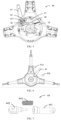
- the clamping device 100 includes a mounting base 10, a rotating module 20, an engagement module 30, a first drive module 40, a clamping module 50, a runner module 60, a second drive module 80, and a limiting module 70.
- the rotating module 20, the engagement module 30, the first drive module 40, the clamping module 50, the runner module 60, the second drive module 80 and the limiting module 70 are all provided on the mounting base 10.
- the first drive module 40 is connected to the rotating module 20, and the rotating module 20 is connected to the clamping module 50, the second drive module 80 is connected to the clamping module 50 and used for driving the clamping module 50 to move away from each other relative to the mounting base 10 so that the clamping device 100 is in a state to be clamped, the first drive module 40 is used for driving the engagement module 30 to rotate, and when the first drive module 40 is in a second position and the engagement module 30 is in an engagement state, the rotating module 20 can rotate synchronously with the engagement module 30; the rotating module 20 moves the clamping module 50 towards each other with respect to the mounting base 10, so that the clamping device 100 clamps an object to be clamped.
- the runner module 60 is connected to the clamping module 50, and the runner module 60 is used for supporting the clamping module 50 and guiding the movement of the clamping module 50.
- the limiting module 70 serves to limit the rotation angle range of the rotating module 20 to prevent a rotation dead zone of the rotating module 20.
- the mounting base 10 is provided with an accommodating space 11, a rotating shaft 12, a grip 13, a mounting portion 14, and a cover plate 15.
- the accommodating space 11 is used for accommodating the rotating module 20, the engagement module 30, the first drive module 40, the clamping module 50, the runner module 60, the second drive module 80 and the limiting module 70, where a rotating shaft 12 is provided at the center of the accommodating space 11, the rotating shaft 12 is used for passing the rotating module 20 and the engagement module 30 therethrough, both the rotating module 20 and the engagement module 30 can rotate around the rotating shaft 12, and when the engagement module 30 is in an engaged state, the engagement module 30 rotates synchronously with the rotating module, and when the engagement module 30 is in a non-engaged state, the engagement module 30 can rotate relative to the rotating module 20.
- a grip 13 is provided on a surface of the mounting base 10 facing away from the accommodating space 11 and is adapted to be gripped by a user to facilitate use and handling of the clamping device 100.
- a mounting portion 14 is provided on a surface of the mounting base 10 facing away from the accommodating space 11 and is used for mounting a calibration assembly.
- the calibration assembly includes a calibration plate.
- the cover plate 15 is used for covering the accommodating space 11 and preventing the rotating module 20, the engagement module 30, the first drive module 40, the clamping module 50, the runner module 60, the second drive module 80 and the limiting module 70 in the accommodating space 11 from being exposed, to enhance the aesthetic appearance of the mounting base 10, and at the same time, the cover plate 15 is used for preventing impurities from entering the accommodating space 11 and interfering with the normal operation of the clamping device 100.
- the rotating module 20 includes a rotating plate 21 and at least two connecting rods 22, where a first end of the connecting rod 22 is rotatably connected to the rotating plate 21, and a second end of the connecting rod 22 is rotatably connected to the clamping module 50.
- the rotating plate 21 is provided with a stroke curve protrusion 211 for cooperating with the engagement module 30 to control the state of the engagement module 30.
- the engagement module 30 includes a ratchet wheel 31 and a ratchet assembly 32.
- the ratchet wheel 31 is rotatably provided to the rotating shaft 12 and fixedly connected to the rotating plate 21, and the ratchet assembly 32 includes a rotating portion 321, a detent 322, a first elastic member 323, a first connector 324, a ratchet stop 325, and a limiting member 326.
- the rotating portion 321 is rotatably provided to the rotating shaft 12, and is rotatable relative to the rotating plate 21 and the ratchet wheel 31.
- a first end of the detent 322 is rotatably provided on the rotating portion 321, a second end of the detent 322 is provided with a ratchet 3221 for engaging with the ratchet wheel 31, a first end of the first connector 324 is rotatably connected to the rotating portion 321, a second end of the first connector 324 is rotatably connected to a first end of the ratchet stop 325, the first end of the ratchet stop 325 is provided with a first protrusion 3251, the first protrusion 3251 abuts against the second end of the detent 322, the first end of the ratchet stop 325 always abuts against the stroke curve protrusion 211, the limiting member 326 is fixed on the mounting base 10, and the second end of the ratchet stop 325 always abuts against the limiting member 326.
- One end of a first elastic member 323 is provided to the mounting base 10, and the other end of the first elastic member 323 is connected to the first end of the detent 322, and the first elastic member 323 is used to move the second end of the detent 322 in a direction close to the ratchet wheel 31.
- the junction of the first connector 324 with the rotating portion 321 and the junction of the first connector 324 with the ratchet stop 325 are each provided with a spring such that when the rotating portion 321 rotates, a first end of the ratchet stop 325 always abuts against the stroke curve protrusion 211 and a second end of the ratchet stop 325 always abuts against the limiting member 326.
- the engagement module 30 includes a friction ratchet wheel 31 provided to the rotating shaft 12, the friction ratchet wheel 31 being fixedly connected to the rotating plate 21, and an eccentric sector wedge rotatably provided to the rotating portion 321, the eccentric sector wedge being for engagement with the friction ratchet wheel 31.
- the first drive module 40 includes a handle 41, a second connector 42, a third connector 43, and a fourth connector 44.
- a first end of the handle 41 is provided with a second protrusion 411
- the second protrusion 411 is rotatably provided on the mounting base 10
- the handle 41 is located on a side of the mounting base 10 facing away from the accommodating space 11, a second connector 42, a third connector 43 and a fourth connector 44 are all provided in the accommodating space 11, a first end of the second connector 42 is rotatably connected to the second protrusion 411 of the handle 41
- a first end of the third connector 43 is rotatably connected to the mounting base 10
- a second end of the second connector 42 and a second end of the third connector 43 are rotatably connected to a first end of the fourth connector 44, and a second end of the fourth connector 44 is rotatably connected to the rotating portion 321.
- the handle 41 is provided with a start position 41a and an end position 41b, and defines a first direction when the handle 41 is rotated from the start position 41a to the end position 41b, and a second direction when the handle 41 is rotated from the end position 41b to the start position 41a.
- the handle 41 is further provided with a first position (not shown) and a second position (not shown), where the first position is a position where the handle 41 is located when the ratchet 3221 and the ratchet wheel 31 change from an engaged state to a disengaged state; the second position is the position where the handle 41 is located when the ratchet 3221 and ratchet wheel 31 transit from the disengaged state to the engaged state, the second position being different when the clamping module 50 is in a different position relative to the mounting base 10.
- the second end of the detent 322 moves in a direction close to the ratchet wheel 31; under the action of the first connector 324, the first end of the ratchet stop 325 slides along the stroke curve protrusion 211 and always abuts against the stroke curve protrusion 211; the ratchet stop 325 rotates relative to the first connector 324 in a first direction; in this process, the engagement module 30 is in a non-engagement state, i.e., the ratchet assembly 32, the ratchet wheel 31 and the rotating plate 21 can rotate relative to each other until the handle 41 moves to the second position; the ratchet 3221 at the second end of the detent 322 is engaged with the ratchet wheel 31; at this moment, the engagement module 30 is in an engaged state, i.e., the ratchet assembly 32 and the ratchet wheel 31 and the rotating plate 21 can rotate synchronously; the handle 41 continues to move in the first direction (the handle 41 moves from the second position to the direction of the end position
- the second protrusion 411 pulls the second connector 42 to move; the second connector 42 pulls the third connector 43 and the fourth connector 44 to move so that the third connector 43 and the fourth connector 44 are not in the same straight line; the third connector 43 and the fourth connector 44 are in an unlocked state; the fourth connector 44 pulls the rotating portion 321 to rotate in the first direction; the second protrusion 411 of the first end of the ratchet stop 325 lifts the second end of the detent 322 in a direction away from the ratchet wheel 31; when the handle 41 is in the first position, the ratchets 3221 are separated from the ratchet wheel 31, and at this time, the engagement module 30 is in an unengaged state, and the ratchet assembly 32 can rotate relative to the ratchet wheel 31 and the rotating plate 21 to apply an external force to the clamping module 50, so that the clamping module 50 moves away relative to the mounting base 10, and the clamping device
- the fourth connector 44 includes a compression outer cylinder 441, a compression rod 442 and a second elastic member 443, where a first end of the compression rod 442 is rotatably connected to a second end of the second connector 42 and a second end of the third connector 43, a second end of the compression rod 442 is sleeved with the compression outer cylinder 441, the compression outer cylinder 441 is rotatably connected to the rotating portion 321, the second elastic member 443 is provided inside the compression outer cylinder 441, and two ends of the second elastic member 443 respectively abut against the compression rod 442 and the compression outer cylinder 441, the compression rod 442 is telescopically movable within the compression outer cylinder 441, and the second elastic member 443 serves to cushion the movement between the compression rod 442 and the compression outer cylinder 441.
- the clamping module 50 includes a pull hook 52 and at least two clamping assemblies 51, where a first end of the clamping assembly 51 is rotatably connected to a second end of the connecting rod 22, and the second end of the clamping assembly 51 extends from the accommodating space 11 to the accommodating space 11; the at least two clamping assemblies 51 can slide relative to the mounting base 10; when the clamping assemblies 51 slide towards each other, the clamping device 100 is in a clamping state, and the clamping assemblies 51 can clamp an object to be clamped; and when the clamping assemblies 51 slide away from each other, the clamping device 100 is in a state to be clamped, and the clamping assemblies 51 release an object to be clamped.
- a pull hook 52 is provided at the second end of the clamping assembly 51, and the pull hook 52 is used for a user to drive the clamping assembly 51 to move apart so that the clamping device 100 is in a state to be clamped.
- the number of clamping assemblies 51 is three, the three clamping assemblies 51 are uniformly provided on the mounting base 10, the three clamping assemblies 51 are all rotatably connected to the rotating module 20, and the three clamping assemblies 51 is movable synchronously to make the clamping effect of the clamping device 100 better.
- the clamping assembly 51 includes a jaw 511, a sliding sleeve 512, a sleeve rod 513, and a first locking assembly 514.
- a first end of the sliding sleeve 512 is rotatably connected to a second end of the connecting rod 22, the second end of the sliding sleeve 512 extends out of the accommodating space 11 from the accommodating space 11, two sides of the sliding sleeve 512 are respectively connected to the runner module 60, the sliding sleeve 512 can reciprocally and telescopically slide relative to the mounting base 10, the sleeve rod 513 is sleeved in the sliding sleeve 512, and the sleeve rod 513 can telescopically slide relative to the sliding sleeve 512, a jaw 511 is provided at the first end of the sleeve rod 513, and the jaw 511 is used for abutting against and clamping the object to be clamped, the first locking assembly 5
- the sliding sleeve 512 is provided with a telescopic groove 5121, a first through-hole 5122, a first sliding groove 5123, a second sliding groove 5124 and a transition groove 5125.
- the telescopic groove 5121 extends from the second end of the sliding sleeve 512 to the first end of the sliding sleeve 512, and the telescopic groove 5121 is used for accommodating a sleeve rod 513, and the sleeve rod 513 reciprocally and telescopically moves relative to the sliding sleeve 512 within the telescopic groove 5121.
- a first through-hole 5122 is provided at one surface of the sliding sleeve 512, and the first through-hole 5122 communicates the telescopic groove 5121 with the outside, the first through-hole 5122 is used for passing the first locking assembly therethrough.
- the first sliding groove 5123 and the second sliding groove 5124 are respectively provided on two sides of the sliding sleeve 512, the first sliding groove 5123 and the second sliding groove 5124 are both used for abutting against the runner module 60, and the first sliding groove 5123 and the second sliding groove 5124 cooperate with the runner module 60 so that the sliding sleeve 512 slides back and forth in a unique direction relative to the mounting base 10.
- a transition groove 5125 is provided at the second end of the sliding sleeve 512, the transition groove 5125 communicats with the telescopic groove 5121 and is used for sliding the first locking assembly 514 so that the sleeve rod 513 can be retracted into the telescopic groove 5121.
- the sleeve rod 513 is provided with a mounting groove 5131 for mounting the first locking assembly 514.
- the first locking assembly 514 includes a locking base 5141, a third elastic member 5142, a fourth elastic member 5143, a thimble 5144, a thimble base 5145, and a button 5146.
- a locking base 5141 is provided on the sliding sleeve 512
- a third elastic member 5142 and a button 5146 are provided on the locking base 5141, and two ends of the third elastic member 5142 respectively abut against the sliding sleeve 512 and the button 5146.
- the fourth elastic member 5143, the thimble 5144 and the thimble base 5145 are all provided in the mounting groove 5131; the thimble base 5145 and the mounting groove 5131 together enclose a mounting cavity 5132; the thimble 5144 and the fourth elastic member 5143 are provided in the mounting cavity 5132; a first end of the fourth elastic member 5143 is fixed to a groove bottom of the mounting groove 5131; a second end of the fourth elastic member 5143 is fixed to a first end of the thimble 5144; and the second end of the thimble 5144 passes through the thimble base 5145 and is inserted into the first through-hole 5122.
- the locking base 5141 is provided with a second through-hole 51411 and a second barrier 51412, where the second through-hole 51411 penetrates the locking base 5141, communicates with the first through-hole 5122 and is used for passing the button 5146 therethrough, the second barrier 51412 is provided at an end of the second through-hole 51411 away from the first through-hole 5122, and the second barrier 51412 is used for blocking the button 5146 from moving in a direction away from the first through-hole 5122 to prevent the button 5146 from being detached from the second through-hole 51411.
- the second end of the thimble 5144 is provided with a transition 51441 that facilitates the thimble 5144 to exit the first through-hole 5122 when the first locking assembly 514 unlocks the sleeve rod 513.
- the transition 51441 is hemispherical, or frustoconical, or conical, or pyramidal.
- the button 5146 includes a pressing portion 51462 extending outward from a surface of the pressing portion 51462, and an extending portion 51461 inserted into the first through-hole 5122 from the second through-hole 51411 to abut against the transition 51441 of the thimble 5144.
- the side wall of the pressing portion 51462 is provided with a first barrier 51464 for cooperating with a second barrier 51412 to limit the range of movement of the button 5146 in a direction close to the first through-hole 5122
- the extending portion 51461 is provided with a third barrier 51463 for cooperating with the second barrier 51412 to limit the range of movement of the button 5146 in a direction away from the first through-hole 5122
- the second barrier 51412 is located between the first barrier 51464 and the third barrier 51463, and both ends of the third elastic member 5142 abut against the sliding sleeve 512 and the third barrier 51463, respectively.
- the pressing portion 51462 drives the extending portion 51461 to push the thimble 5144 out of the first through-hole 5122, the thimble 5144 retracts into the mounting cavity 5132, the sleeve rod 513 and the sliding sleeve 512 are in an unlocked state, the sleeve rod 513 can slide back and forth relative to the sliding sleeve 512, the second barrier 51412 blocks the movement of the first barrier 51464, preventing the extending portion 51461 from penetrating out of the first through-hole 5122 and entering the mounting cavity 5132, and hindering the movement of the sleeve rod 513.
- the third elastic member 5142 pushes the extending portion 51461 away from the first through-hole 5122, the second barrier 51412 blocks the movement of the third barrier 51463, prevents the extending portion 51461 from leaving the second through-hole 51411, and the button 5146 is disengaged from the locking base 5141.
- the fourth elastic member 5143 pushes the thimble 5144 out of the thimble holder 5145 and into the first through-hole 5122, the first locking assembly 514 is in a locked state, and the sleeve rod 513 and the sliding sleeve 512 are again relatively fixed.
- the third elastic member 5142 and the fourth elastic member 5143 are springs.
- the pressing portion 51462 and the extending portion 51461 of the button 5146 are independent structures, and the pressing portion 51462 and the extending portion 51461 are connected into the second through-hole 51411 from both ends of the second through-hole 51411, respectively.
- the sleeve rod 513 is provided with a plurality of mounting grooves 5131 which are provided at intervals along the extending direction of the sleeve rod 513, and the thimble 5144, the fourth elastic member 5143 and the thimble base 5145 are mounted in each mounting groove 5131.
- the thimble 5144, the fourth elastic member 5143, and the thimble holder 5145 are installed in the same manner as described above.
- the plurality of mounting grooves 5131 enable the sleeve rod 513 to be adjusted in the presence of a plurality of telescoping gears relative to the sliding sleeve 512.
- the runner module 60 includes a first mounting frame 61, a second mounting frame 62, a first runner 63, a second runner 64, a third runner 65, and a fourth runner 66.
- the first mounting frame 61 and the second mounting frame 62 are both provided on the mounting base 10
- the first mounting frame 61 and the second mounting frame 62 are respectively located on two sides of the sliding sleeve 512
- the first runner 63 and the second runner 64 are both rotatably provided on the first mounting frame 61
- the first runner 63 and the second runner 64 are provided perpendicularly to each other
- the first runner 63 abuts against the groove bottom of the first sliding groove 5123
- the second runner 64 abuts against the groove wall of the first sliding groove 5123.
- the third runner 65 and the fourth runner 66 are both rotatably provided on the second mounting frame 62, the third runner 65 and the fourth runner 66 are provided perpendicular to each other, the third runner 65 abuts against the groove bottom of the second sliding groove 5124, and the fourth runner 66 abuts against the groove wall of the second sliding groove 5124.
- the first runner 63, the second runner 64, the third runner 65 and the fourth runner 66 cooperate together so that the sliding groove has only one direction of movement for telescopic movement relative to the mounting base 10.
- the runner module 60 further includes a fifth runner, a sixth runner, a seventh runner and an eighth runner, where the fifth runner and the sixth runner are all rotatably provided on the first mounting frame 61, the fifth runner and the sixth runner are provided perpendicular to each other, the fifth runner is in contact with the groove bottom of the first sliding groove 5123, and the sixth runner is in contact with the groove wall of the first sliding groove 5123.
- the seventh runner and the eighth runner are both rotatably provided on the second mounting frame 62, the seventh runner and the eighth runner are provided perpendicular to each other, the seventh runner is in contact with the groove bottom of the second sliding groove 5124, and the eighth runner is in contact with the groove wall of the second sliding groove 5124.
- the first runner 63, the second runner 64, the third runner 65, the fourth runner 66, the fifth runner, the sixth runner, the seventh runner, and the eighth runner cooperate so that the sliding sleeve 512 is smoother when sliding relative to the mounting base 10.
- the limiting module 70 includes a first limiting protrusion 71, a second limiting protrusion 72, a limiting elastic member 73 and a limiting fixing member 74.
- the first limiting protrusion 71 and the second limiting protrusion 72 are fixedly provided on the mounting base 10; the limiting fixing member 74 fixes a limiting elastic member 73 on the mounting base 10; a first end of the limiting elastic member 73 abuts against the first limiting protrusion 71; the first end of the limiting elastic member 73 is used for limiting the range of motion of the rotating plate 21 in a first direction; a second end of the limiting elastic member 73 abuts against the second limiting protrusion 72; the second end of the limiting elastic member 73 is used for limiting the range of motion of the rotating plate 21 in a second direction; and the limiting elastic member 73 is used for preventing the rotating plate 21 from entering a rotation dead zone of the rotating plate 21 due to too large rotating amplitude, that is, the rotating plate 21, the connecting rod 22 and the sliding sleeve 512 are on the same straight line.
- the second drive module 80 includes a third mounting frame 81, a support shaft 82, and a coil spring 83.
- the third mounting frame 81 is fixedly provided on the mounting base 10
- the support shaft 82 is provided on the third mounting frame 81
- the coil spring 83 is provided on the support shaft 82, and is connected to a first end of the sliding sleeve 512; when an external force is applied to the pull hook 52 to move the sliding sleeve 512 away from the mounting base 10, the coil spring 83 moves synchronously with the sliding sleeve 512, and at this time, the coil spring 83 is in a compressed state; when the external force is cancelled, the coil spring 83 drives the sliding sleeve 512 to move closer to the mounting base 10 against the elastic force of deformation, and the jaw 511 clamps an object to be clamped.
- the second drive module 80 includes a tension spring, both ends of which are connected to the mounting base 10 and the clamping assembly 51, respectively.
- the second drive module 80 includes a central coil spring 83 sleeved on the rotating shaft 12, the central coil spring 83 is connected to the rotating plate 21, and the central coil spring 83 is used for driving the rotating plate 21 to rotate.
- the clamping assembly 51 when the clamping device 100 initially clamps the objects to be clamped, the clamping assembly 51 is at different positions, and through the cooperation of the stroke curve protrusion 211 and the ratchet assembly 32, the position where the ratchet 3221 engages with the ratchet wheel 31 can be controlled, so that when clamping devices 100 clamp different sizes of objects to be clamped, the retraction length of the clamping assembly 51 relative to the mounting base 10 is the same from initially clamping the objects to completely clamping the objects to be clamped.
- the clamping device 100 includes a mounting base 10, a clamping module 50, a rotating module 20, a first drive module 40 and an engagement module 30;
- the clamping module 50 includes at least two clamping assemblies 51;
- the rotating module 20 includes a rotating plate 21 and at least two connecting rods 22; a first end of the connecting rod 22 is rotatably connected to the rotating plate 21; a second end of the connecting rod 22 is rotatably connected to a first end of the clamping assembly 51;
- the rotating plate 21 is provided with a stroke curve protrusion 211;
- the engagement module 30 includes a ratchet wheel 31 and a ratchet wheel assembly 32;
- the ratchet wheel 31 is coaxially and fixedly connected to the rotating plate 21;
- the ratchet assembly 32 is provided coaxially with the rotating plate 21, and the ratchet assembly 32 and the rotating plate 21 is movable relatively;
- the ratchet assembly 32 and the stroke curve protrusion 211 cooperate together so that the first drive module 40 drives
- the clamping device 100 can make the retraction amplitude of the clamping module 50 uniform when the clamping module 50 clamps the object to be clamped at any position, thereby making the clamping device 100 clamp the object to be clamped with uniform force.
- FIG. 14 is a schematic illustration of an application environment for a method for determining a curve on which a stroke curve protrusion of a clamping device is located according to an embodiment of the present application, the application environment including a clamping device 100 including a mounting base 10, a first drive module 40, a clamping module 50, a rotating plate 21, a connecting rod 22, a ratchet wheel 31 and a ratchet assembly 32.
- the rotating plate 21, the ratchet wheel 31 and the ratchet assembly 32 are all rotatably provided on the mounting base 10; the rotating plate 21 and the ratchet wheel 31 are relatively fixed; the ratchet assembly 32 can rotate relative to the ratchet wheel 31 and the rotating plate 21; a first end of the connecting rod 22 is rotatably connected to the rotating plate 21; a second end of the connecting rod 22 is rotatably connected to the clamping module 50; the first drive module 40 drives the ratchet assembly 32 to rotate; and when the ratchet assembly 32 engages with the ratchet wheel 31, the ratchet assembly 32 rotates synchronously with the ratchet wheel 31 and the rotating plate 21 to drive the clamping module 50 to retract towards the mounting base 10.
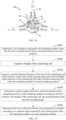
- FIG. 15 shows a flow chart of a method for determining a curve of a stroke curve protrusion of a clamping device according to the present application, as shown in FIG. 15 , including the steps of:
- S101 Determine a first distance required by the clamping module when the first drive module moves from a second position to an end position.
- the ratchet assembly and the ratchet wheel change from a separated state to an engaged state, and in the process of moving from the second position to the end position, the first drive module drives the ratchet wheel and the rotating plate to rotate synchronously, and drives the clamping modules to move towards each other via the connecting rod (retracting relative to the mounting base).
- the first distance is a distance preset by the user, i.e. the user wants to control the retraction distance of the clamping module relative to the mounting base during the movement of the first drive module from the second position to the end position, the first distance being a constant value.
- the sampling position of the clamping module refers to the position of the clamping module relative to the mounting base, and each sampling position corresponds to a position where the ratchet assembly and the ratchet wheel are engaged; when the sampling positions of the clamping module are different, the engaging positions of the ratchet assembly and the ratchet wheel are different; therefore, different sampling positions of the ratchet module need to be acquired to solve different engaging positions of the ratchet assembly and the ratchet wheel.
- S 104 Calculate a rotation angle required by the rotating plate when the clamping module is at each sampling position according to the first distance, the length of the connecting rod, the second distance and the first included angle.
- S105 Determine the curve of the stroke curve protrusion according to the rotation angle required to rotate the plate when the clamping module is in each sampling position.
- the corresponding rotation angles are also different; after the rotation angle obtained by reversely rotating the first drive module from the end position, the position where the ratchet assembly engages with the ratchet wheel is a second position, and the curves where several second positions are located are curves where the stroke curve protrusion is located.
- step S105 includes:
- FIG. 17 shows a functional block diagram of a device 90 for determining the curve on which the stroke curve protrusion of a clamping device is located, the apparatus 90 including a first determination module 91, a first acquisition module 92, a second acquisition module 93, a calculation module 94 and a second determination module 95.
- a first determination module 91 is configured to determine a first distance required by the clamping module when the first drive module moves from a second position to an end position; a first acquisition module 92 is configured to acquire a length of the connecting rod; a second acquisition module 93 is configured to acquire a second distance between a first end of the connecting rod and a rotation center point of the rotating plate and a first included angle between a first connecting line and a second connecting line when the clamping module is at each sampling position, where the first connecting line is a connecting line between the second end of the connecting rod and the rotation center point of the rotating plate, and the second line is a connecting line between the first end of the connecting rod and the rotation center point of the rotating plate; a calculation module 94 is configured to calculate a rotation angle required by the rotating plate when the clamping module is at each sampling position according to the first distance, the length of the connecting rod, the second distance and the first included angle; and a second determination module 95 is configured to determine the curve of the stroke curve protrusion according to the rotation angle required to rotate the plate
- the second determination module 95 includes a mapping unit 951, a calculation unit 952 and a determination unit 953.
- a mapping unit 951 is configured to map each of the sampling positions onto the rotating plate;
- a calculation unit 952 is configured to calculate a required distance between the ratchet wheel and the ratchet assembly according to a rotation angle required to rotate the plate when the clamping module is in each sampling position;
- a determination unit 953 is configured to determine the stroke curve protrusion according to the required distance between the ratchet wheel and ratchet assembly when the clamping module is in each sampling position.
- the present application also provides an embodiment of a computing apparatus 200, see FIG. 18 , which is a schematic diagram of an embodiment of a computing apparatus 200 of the present application, the controller of the computing apparatus 200 including: at least one processor 201; and a memory 202 communicatively coupled to the at least one processor 201, one of which is exemplified in FIG. 18 .
- the memory 202 stores instructions that are executable by the at least one processor 201 to enable the at least one processor 201 to perform a method for determining a curve of a curve of travel of a clamping device as described above referring to FIGS. 15-16 and a device for determining a curve of a curve of travel of a clamping device as described above referring to FIG. 17 .
- the processors 201 and the memory 202 may be connected via a bus or in other ways, and via a bus connection exemplified in FIG. 18 .
- the memory 202 is a non-volatile computer-readable storage medium that may be used to store a non-volatile software program, a non-volatile computer-executable program, and modules, such as program instructions/modules corresponding to a method for determining a curve of a stroke curve protrusion of a clamping device in an embodiment of the present application, such as the modules shown in FIG. 17 .
- the processor 201 executes various functional applications of the server and data processing by running non-volatile software programs, instructions and modules stored in the memory 202, i.e., implementing a method for determining the curve on which the stroke curve protrusion of the clamping device is located, according to the embodiments of the method described above.
- the memory 202 may include a program storage area and a data storage area, where the program storage area may store an operating system and an application program required by at least one function; the data storage area may store data or the like created from the use of a device that determines the curve on which the stroke curve of the clamping device is located.
- the memory 202 may include a high-speed random access memory and may also include a non-volatile memory, such as at least one magnetic disk storage apparatus, flash memory apparatus, or other non-volatile solid state storage apparatuses.
- the memory 202 may optionally include memory remotely located with respect to the processor 201, which may be connected via a network to a device for determining the curve of the stroke curve protrusion of the clamping device. Examples of such networks include, but are not limited to, the Internet, intranets, local area networks, mobile communication networks, and combinations thereof.
- the one or more modules are stored in the memory 202 and, when executed by the one or more processors 201, perform a method for determining the curve on which the curve of the stroke curve of the clamping device is located in any of the method embodiments described above, e.g. perform the method steps of FIGS. 15 to 16 described above, and perform a device for determining the curve on which the curve of the stroke curve of the clamping device is located as described above in FIG. 17 .
- the above-mentioned product can execute the method provided in the embodiment of the present application, and has corresponding functional modules and advantageous effects for executing the method.
- the method provided in the embodiment of the present application can execute the method provided in the embodiment of the present application, and has corresponding functional modules and advantageous effects for executing the method.
- Embodiments of the present application also provide a non-volatile computer-readable storage medium having stored thereon computer-executable instructions that are executed by one or more processors, e.g. to perform the method steps of determining a curve on which a curve of travel of a clamping device is projected described above with respect to FIGS. 15-16 , and to perform the apparatus for determining a curve on which a curve of travel of a clamping device is projected described above with respect to FIG. 17 .
- Embodiments of the present application also provide a computer program product including a computer program stored on a non-volatile computer readable storage medium, the computer program including program instructions which, when executed by a computer, cause the computer to perform a method for determining a curve on which a curve on which a stroke curve protrusion of a clamping device is located is to be located in any of the method embodiments described above, for example, performing the method steps of FIGS. 15 to 16 described above, and performing a device for determining a curve on which a curve on which a stroke curve protrusion of a clamping device is located is to be located as described above in FIG. 17 .
Landscapes
- Physics & Mathematics (AREA)
- General Physics & Mathematics (AREA)
- Engineering & Computer Science (AREA)
- Mechanical Engineering (AREA)
- Clamps And Clips (AREA)
- Chairs For Special Purposes, Such As Reclining Chairs (AREA)
Abstract
Description
- This application claims priority to
Chinese Patent Application No. 202210313612.0 filed on March 28, 2022 by China Patent Office - The present application relates to the technical field of vehicle device, and in particular to a clamping device and a method for determining a curve of a stroke curve protrusion in a clamping device.
- With the development of automobile industry and the improvement of people's living standards, more and more families have domestic cars. It is necessary to detect the steering of the wheels after the automobiles are produced, and after a period of use, there might be deviations for the steering of the automobiles, for either situation of which, four-wheel alignment is involved. Through the calibration plate and calibration equipment, the four-wheel parameters of the vehicle are collected and adjusted to ensure that the vehicle maintains good driving performance and improve the reliability of the vehicle.
- In carrying out the examples of the present application, the inventors found that: at present, a tire clamp used in the four-wheel positioning process, due to the use of connecting rod rotation transmission, the length of each extension of clamping arm is inconsistent, resulting in different forces to hold the tire at different positions, affecting the positioning work.
- The technical problem to be mainly solved by the embodiments of the present application is to provide a clamping device and a method for determining a curve of a stroke curve protrusion in the clamping device, so that when a clamping module clamps a tire at any position, the retraction length of the clamping assembly is consistent, thereby making the force with which the clamping device grips an object to be clamped the same.
- In order to solve the above technical problem, one technical solution adopted by the embodiments of the present application is to provide a clamping device including a mounting base, a clamping module, a rotating module, a first drive module and an engagement module, a clamping module including at least two clamping assemblies, where the at least two clamping assemblies are both provided on the mounting base, and the at least two clamping assemblies are movable with respect to the mounting base; the rotating module includes a rotating plate and at least two connecting rods, the rotating plate is rotatably provided on the mounting base, first ends of the at least two connecting rods are both rotatably connected to one of the rotating plate, a second end of the connecting rod is rotatably connected to one of the clamping assemblies, and the rotating plate is provided with a stroke curve protrusion; a first drive module is provided on the mounting base; the engagement module includes a ratchet wheel and a ratchet assembly, where the ratchet wheel is fixed to the rotating plate, the ratchet assembly can rotate relative to the rotating plate, the first drive module is connected to the ratchet assembly, and when the first drive module is driven, the first drive module drives the ratchet assembly to move relative to the rotating module, where when the first drive module is located at a first position, the ratchet wheel and the ratchet assembly are separated, when the first drive module is located at a second position, the ratchet wheel and the ratchet assembly are engaged, and when the first drive module is located at an end position, the first drive module is locked, and when the first drive module moves from a second position to an end position, the ratchet assembly drives the ratchet wheel to rotate, thereby driving the rotating module to rotate; when the rotating plate rotates, the stroke curve protrusion being used for adjusting the distance between the ratchet wheel and the ratchet assembly, so that when the clamping module is at different positions, the second position is different, so that when the first drive module moves from the second position to the end position, the rotating plate rotates at different angles, and the moving distance of the clamping module at different positions relative to the mounting base remains the same.
- Alternatively, the ratchet assembly includes a rotating portion, a detent, a first elastic member, a first connector, a ratchet stop and a limiting member, the rotating portion is provided coaxially with the rotating module, and the rotating portion can rotate relative to the rotating module, a first end of the detent is connected to the rotating portion, a first end of the first elastic member is connected to the mounting base, a second end of the first elastic member is connected to the first end of the detent, the second end of the detent is provided with a ratchet, and the first end of the first connector is rotatably connected to the rotating portion; the second end of the first connector is rotatably connected to the first end of the ratchet stop, the first end of the ratchet stop is provided with a first protrusion, the first protrusion abuts against the second end of the detent, the first end of the ratchet stop abuts against the stroke curve protrusion, the limiting member is fixed to the mounting base, and the second end of the ratchet stop abuts against the limiting member; when the first drive module drives the rotating portion to rotate, the rotating portion rotates with respect to the ratchet wheel, under the action of the first elastic member, the ratchet of the second end of the detent approaches the ratchet wheel, the ratchet stop always abuts against the stroke curve protrusion under the action of the first connector and the limiting member, the ratchet stop rotates with respect to the first connector, the first protrusion of the first end of the ratchet stop approaches the ratchet wheel, until the ratchet engages the ratchet wheel when the first drive module is at the second position, the first drive module continues to drive the rotating portion to move, and the detent moves the ratchet wheel so that the rotating plate moves the clamping assembly via the connecting rod.
- Alternatively, the first drive module includes a handle, a second connector, a third connector and a fourth connector; a first end of the handle is rotatably provided on the mounting base, a second protrusion extends from the first end of the handle, a first end of the second connector is rotatably connected to the second protrusion, a first end of the third connector is rotatably connected to the mounting base, a second end of the third connector, a second end of the second connector and a first end of the fourth connector are rotatably connected, and a second end of the fourth connector is rotatably connected to the rotating portion; when the handle rotates from a start position to an end position and drives the second connector, the third connector and the fourth connector to move via the second protrusion to push the rotating portion to rotate; when the third connector and the fourth connector are in the same straight line, the first drive module is in a self-locked state to lock the rotating portion; and when the handle rotates from the end position to the start position, the handle drives the second connector, the third connector and the fourth connector to move via the second protrusion, the third connector and the fourth connector are not in the same straight line, the first drive module is in an unlocked state, and the rotating portion is movable relative to the mounting base.
- Alternatively, the fourth connector includes a compression outer cylinder, a compression rod and a second elastic member, a first end of the compression rod is rotatably connected to a second end of the third connector and a second end of the second connector, a second end of the compression rod is sleeved with the compression outer cylinder, the compression outer cylinder is rotatably connected to the rotating portion, the second elastic member is provided inside the compression outer cylinder, two ends of the second elastic member respectively abut against the compression rod and the compression outer cylinder, the compression rod is telescopically movable inside the compression outer cylinder, and the second elastic member serves to cushion the movement between the compression rod and the compression outer cylinder.
- Alternatively, the clamping assembly includes a jaw, a sliding sleeve, a sleeve rod and a first locking module; the sliding sleeve is provided on the mounting base, the sliding sleeve is movable relative to the mounting base, a first end of the sliding sleeve of one of the clamping assemblies is rotatably connected to a second end of one of the connecting rods, the sliding sleeve is provided with a telescopic groove, and the telescopic groove extends from the second end of the sliding sleeve to the first end of the sliding sleeve; the jaw is fixed to a first end of the sleeve rod, a second end of the sleeve rod is inserted into a telescopic groove of the sliding sleeve from a second end of the sliding sleeve, and the sleeve rod is movable along the telescopic groove so that the first end of the sleeve rod moves in a direction away from the sliding sleeve or moves in a direction close to the sliding sleeve; the first locking module is provided on the sliding sleeve and the sleeve rod, and when the first locking module is in a locked state, the sliding sleeve and the sleeve rod are fixed, and when the first locking module is in an unlocked state, the sleeve rod is allowed to slide relative to the sliding sleeve.
- Alternatively, the first locking module includes a locking base, a third elastic member, a fourth elastic member, a thimble and a button; the sliding sleeve is provided with a first through-hole in communication with the telescopic groove, the locking base is fixed to the sliding sleeve and provided with a second through-hole, the second through-hole is in communication with the first through-hole, the button includes a pressing portion and an extending portion extending from the pressing portion, the extending portion is inserted into the second through-hole, and the extending portion is movable along the second through-hole and is inserted into the first through-hole from the second through-hole or retracted into the second through-hole from the first through-hole, and the third elastic member is located in the second through-hole; a first end of the third elastic member abuts against the pressing portion, and a second end of the third elastic member abuts against the sliding sleeve; the sleeve rod is provided with a mounting groove, the fourth elastic member and the thimble are provided in the mounting groove, a first end of the fourth elastic member is fixed to a groove bottom of the mounting groove, and a second end of the fourth elastic member is fixed to a first end of the thimble; when the sleeve rod slides to a position where the first through-hole corresponds to the mounting groove, under the action of the fourth elastic member, the second end of the thimble protrudes from the notch of the mounting groove and is inserted into the first through-hole, and the first locking module is in a locked state; and when the pressing portion is forced towards the sleeve rod, the extending portion is inserted into the first through-hole from the second through-hole, and the second end of the thimble is pushed out of the first through-hole, the first locking module is in an unlocked state.
- Alternatively, a side wall of the pressing portion extends with a first barrier; the locking base is provided with a second barrier located at an end of the second through-hole away from the first through-hole, and the second barrier is used for blocking the first barrier.
- Alternatively, the third elastic member is a spring and is sleeved over the extending portion, and/or the second end of the thimble is provided with a transition.
- Alternatively, the clamping device further includes at least two runner modules, each of the at least two runner modules being fixed to the mounting base, a sliding sleeve of one of the clamping assemblies being slidably provided on one of the runner modules.
- Alternatively, the runner module includes a first mounting frame, a second mounting frame, a first runner, a second runner, a third runner and a fourth runner, where the first mounting frame and the second mounting frame are relatively fixed to the mounting base, the first runner and the second runner are rotatably provided on the first mounting frame, the first runner and the second runner both abut against a first side surface of the sliding sleeve, the first runner and the second runner are provided perpendicular to each other, and the third runner and the fourth runner are rotatably provided on the second mounting frame; the third runner and the fourth runner each abut against a second side surface of the sliding sleeve, and the third runner and the fourth runner are provided perpendicular to each other.
- Alternatively, the first side surface of the sliding sleeve is provided with a first sliding groove, the first runner abuts against a groove bottom of the first sliding groove, and the second runner abuts against a groove wall of the first sliding groove; a second side surface of the sliding sleeve is provided with a second sliding groove, the third runner abuts against a groove bottom of the second sliding groove, and the fourth runner abuts against a groove wall of the second sliding groove.
- Alternatively, the clamping device further includes a limiting module, where the limiting module is provided on the mounting base, the limiting module includes a first limiting protrusion, a second limiting protrusion, a limiting elastic member and a limiting fixing member, the first limiting protrusion and the second limiting protrusion are both provided on the mounting base, the limiting fixing member fixes the limiting elastic member to the mounting base afterward, a first end of the limiting elastic member abuts against the first limiting protrusion, and a second end of the limiting elastic member abuts against the second limiting protrusion.
- Alternatively, the clamping device further includes a second drive module, the second drive module includes a third mounting frame, a support shaft and a coil spring, the third mounting frame is provided in the mounting base, the support shaft is connected to the third mounting frame through the coil spring, and the coil spring is connected to one of the clamping assemblies.
- In order to solve the above technical problem, another technical solution adopted by the embodiments of the present application is to provide a method for determining a curve of a stroke curve protrusion in a clamping device, the method including: determining a first distance required by the clamping module when the first drive module moves from a second position to an end position; acquiring a length of the connecting rod; acquiring a second distance between a first end of the connecting rod and a rotation center point of the rotating plate and a first included angle between a first connecting line and a second connecting line when the clamping module is at each sampling position, where the first connecting line is a connecting line between the second end of the connecting rod and the rotation center point of the rotating plate, and the second line is a connecting line between the first end of the connecting rod and the rotation center point of the rotating plate; calculating a rotation angle required by the rotating plate when the clamping module is at each sampling position according to the first distance, the length of the connecting rod, the second distance and the first included angle; and determining the curve of the stroke curve protrusion according to the rotation angle required to rotate the plate when the clamping module is in each sampling position.
- Alternatively, the step of determining the curve of the stroke curve protrusion according to the rotation angle required to rotate the plate when the clamping module is in each sampling position further includes: mapping each of the sampling positions onto the rotating plate; calculating a required distance between the ratchet wheel and the ratchet assembly according to a rotation angle required to rotate the plate when the clamping module is in each sampling position; and determining the stroke curve protrusion according to the required distance between the ratchet wheel and ratchet assembly when the clamping module is in each sampling position.
- In order to solve the above technical problem, still another technical solution adopted by the embodiments of the present application is to provide a device for determining a curve of a stroke curve protrusion of a clamping device, the device including: a first determination module configured to determine a first distance required by the clamping module when the first drive module moves from a second position to an end position; a first acquisition module configured to acquire a length of the connecting rod; a second acquisition module configured to acquire a second distance between a first end of the connecting rod and a rotation center point of the rotating plate and a first included angle between a first connecting line and a second connecting line when the clamping module is at each sampling position, where the first connecting line is a connecting line between the second end of the connecting rod and the rotation center point of the rotating plate, and the second line is a connecting line between the first end of the connecting rod and the rotation center point of the rotating plate; a calculation module configured to calculate a rotation angle required by the rotating plate when the clamping module is at each sampling position according to the first distance, the length of the connecting rod, the second distance and the first included angle; and a second determination module configured to determine the curve of the stroke curve protrusion according to the rotation angle required to rotate the plate when the clamping module is in each sampling position.
- In order to solve the above technical problem, another technical solution adopted by the embodiments of the present application is to provide a detection apparatus including: a controller including: at least one processor, and a memory communicatively coupled to the at least one processor; where the memory stores instructions executable by the at least one processor, the instructions being executed by the at least one processor to enable the at least one processor to perform the method as described above.
- In order to solve the above technical problem, another technical solution adopted by the embodiments of the present application is to provide a non-transitory computer-readable storage medium storing computer-executable instructions for causing a server to perform the method as described above.
- Advantageous effects of the embodiments of the present application are: in the embodiment of the present application, the technical solution that the clamping device uses a rotating module including a rotating plate and a connecting rod, where the connecting rod is rotatably connected to a clamping module and the rotating plate, respectively, and the rotating plate is provided with a stroke curve protrusion; and an engagement module including a ratchet wheel and a ratchet assembly, where the ratchet assembly always abuts against the stroke curve protrusion so as to adjust the engagement position of the ratchet assembly and the ratchet wheel. According to the described technical solution, the technical problem of a clamping device that when a first driving module rotates at the same angle, the retraction distance of the clamping module relative to a mounting base is inconsistent is solved, and the technical effect that when the clamping module is at different positions, in a process where the first driving module rotates to an end position after the ratchet assembly and the ratchet wheel are engaged, the retraction distance of the clamping module relative to the mounting base remains the same is achieved.
- In order that the detailed description of the present application or the prior art may be more clearly understood, a brief description of the drawings that accompany the detailed description of the application or the prior art is set forth below. Throughout the drawings, like elements or portions are generally identified by like reference numerals. In the drawings, elements or portions may not necessarily be drawn to scale.
-
FIG. 1 is an exploded view from a perspective of a clamping device according to an embodiment of the present application; -
FIG. 2 is an exploded view from a perspective of a mounting base in a clamping device according to an embodiment of the present application; -
FIG. 3 is an exploded view from a perspective of a rotating module in a clamping device according to an embodiment of the present application; -
FIG. 4 is an exploded view from a perspective of an engagement module in a clamping device according to an embodiment of the present application; -
FIG. 5 is a schematic view from a perspective of a first drive module in a clamping device according to an embodiment of the present application; -
FIG. 6 is a schematic view from another perspective of a first drive module in a clamping device according to an embodiment of the present application; -
FIG. 7 is an exploded view from a perspective of a fourth connector in a clamping device according to an embodiment of the present application; -
FIG. 8 is an exploded view from a perspective of a clamping module in a clamping device according to an embodiment of the present application; -
FIG. 9 is a schematic view from a perspective of a sliding sleeve and a sleeve rod in a clamping device according to an embodiment of the present application; -
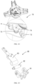
FIG. 10 is a cross-sectional view from a perspective of the first locking assembly of the clamping device according to an embodiment of the present application; -
FIG. 11 is an exploded view from a perspective of a runner module in a clamping device according to an embodiment of the present application; -
FIG. 12 is an enlarged view from a perspective of a limiting module in a clamping device according to an embodiment of the present application; -
FIG. 13 is an exploded view from a perspective of a second drive module in a clamping device according to an embodiment of the present application; -
FIG. 14 is a schematic diagram of an application environment of a method for determining a curve of a stroke curve protrusion of a clamping device according to another embodiment of the present application; -
FIG. 15 is a flow chart of a method for determining a curve of a stroke curve protrusion of a clamping device according to another embodiment of the present application; -
FIG. 16 is a flowchart of step S105 in the method for determining the curve of the stroke curve protrusion of the clamping device according to another embodiment of the present application; -
FIG. 17 is a structural block diagram of a device for determining a curve on which a stroke curve protrusion of a clamping device is located according to another embodiment of the present application; and -
FIG. 18 is a schematic diagram of a computing apparatus according to yet another embodiment of the present application. - To facilitate an understanding of the present application, a more particular description of the application will be rendered by reference to specific embodiments thereof which are illustrated in the appended drawings. It will be understood that when an element is referred to as being "fixed to" to another element, it can be directly on the other element or intervening elements may be present. When an element is referred to as being "connected" to another element, it can be directly connected to the other element or intervening elements may be present. As used in the description, the terms "upper", "lower", "inner", "outer", "vertical", "horizontal", and the like indicate orientations or positional relationships based on the orientation or positional relationships shown in the drawings, are merely for convenience in describing and simplifying the present application, and do not indicate or imply that the referenced devices or elements must have a particular orientation, be constructed and operated in a particular orientation, and thus are not to be construed as limiting the present application. Further, the terms "first", "second", etc. are used for descriptive purposes only and are not to be construed as indicating or implying relative importance.
- Unless defined otherwise, all technical and scientific terms used in the specification have the same meaning as commonly understood by a person skilled in the technical field to which this application belongs. The terminology used in the description of the present application is used for the purpose of describing particular embodiments only and is not intended to be limiting of the application. As used herein, the term "and/or" includes any and all combinations of one or more of the associated listed items.
- Further, the technical features involved in the different embodiments of the present application described below can be combined with each other as long as they do not conflict with each other.
- Referring to
FIG. 1 , theclamping device 100 includes amounting base 10, a rotatingmodule 20, anengagement module 30, afirst drive module 40, aclamping module 50, arunner module 60, asecond drive module 80, and a limitingmodule 70. Therotating module 20, theengagement module 30, thefirst drive module 40, theclamping module 50, therunner module 60, thesecond drive module 80 and the limitingmodule 70 are all provided on themounting base 10. Thefirst drive module 40 is connected to therotating module 20, and therotating module 20 is connected to theclamping module 50, thesecond drive module 80 is connected to theclamping module 50 and used for driving theclamping module 50 to move away from each other relative to the mountingbase 10 so that theclamping device 100 is in a state to be clamped, thefirst drive module 40 is used for driving theengagement module 30 to rotate, and when thefirst drive module 40 is in a second position and theengagement module 30 is in an engagement state, the rotatingmodule 20 can rotate synchronously with theengagement module 30; the rotatingmodule 20 moves theclamping module 50 towards each other with respect to the mountingbase 10, so that theclamping device 100 clamps an object to be clamped. Therunner module 60 is connected to theclamping module 50, and therunner module 60 is used for supporting theclamping module 50 and guiding the movement of theclamping module 50. The limitingmodule 70 serves to limit the rotation angle range of therotating module 20 to prevent a rotation dead zone of therotating module 20. - Referring to
FIG. 2 , the mountingbase 10 is provided with anaccommodating space 11, a rotatingshaft 12, agrip 13, a mountingportion 14, and acover plate 15. Theaccommodating space 11 is used for accommodating therotating module 20, theengagement module 30, thefirst drive module 40, theclamping module 50, therunner module 60, thesecond drive module 80 and the limitingmodule 70, where arotating shaft 12 is provided at the center of theaccommodating space 11, the rotatingshaft 12 is used for passing the rotatingmodule 20 and theengagement module 30 therethrough, both therotating module 20 and theengagement module 30 can rotate around the rotatingshaft 12, and when theengagement module 30 is in an engaged state, theengagement module 30 rotates synchronously with the rotating module, and when theengagement module 30 is in a non-engaged state, theengagement module 30 can rotate relative to therotating module 20. Agrip 13 is provided on a surface of the mountingbase 10 facing away from theaccommodating space 11 and is adapted to be gripped by a user to facilitate use and handling of theclamping device 100. A mountingportion 14 is provided on a surface of the mountingbase 10 facing away from theaccommodating space 11 and is used for mounting a calibration assembly. In some embodiments, the calibration assembly includes a calibration plate. Thecover plate 15 is used for covering theaccommodating space 11 and preventing the rotatingmodule 20, theengagement module 30, thefirst drive module 40, theclamping module 50, therunner module 60, thesecond drive module 80 and the limitingmodule 70 in theaccommodating space 11 from being exposed, to enhance the aesthetic appearance of the mountingbase 10, and at the same time, thecover plate 15 is used for preventing impurities from entering theaccommodating space 11 and interfering with the normal operation of theclamping device 100. - Regarding the above-mentioned
rotating module 20, referring toFIG. 3 , the rotatingmodule 20 includes arotating plate 21 and at least two connectingrods 22, where a first end of the connectingrod 22 is rotatably connected to therotating plate 21, and a second end of the connectingrod 22 is rotatably connected to theclamping module 50. The rotatingplate 21 is provided with astroke curve protrusion 211 for cooperating with theengagement module 30 to control the state of theengagement module 30. - With respect to the
engagement module 30 described above, referring toFIG. 4 , theengagement module 30 includes aratchet wheel 31 and aratchet assembly 32. Theratchet wheel 31 is rotatably provided to therotating shaft 12 and fixedly connected to therotating plate 21, and theratchet assembly 32 includes arotating portion 321, adetent 322, a firstelastic member 323, afirst connector 324, aratchet stop 325, and a limitingmember 326. The rotatingportion 321 is rotatably provided to therotating shaft 12, and is rotatable relative to therotating plate 21 and theratchet wheel 31. A first end of thedetent 322 is rotatably provided on therotating portion 321, a second end of thedetent 322 is provided with aratchet 3221 for engaging with theratchet wheel 31, a first end of thefirst connector 324 is rotatably connected to therotating portion 321, a second end of thefirst connector 324 is rotatably connected to a first end of theratchet stop 325, the first end of theratchet stop 325 is provided with afirst protrusion 3251, thefirst protrusion 3251 abuts against the second end of thedetent 322, the first end of theratchet stop 325 always abuts against thestroke curve protrusion 211, the limitingmember 326 is fixed on the mountingbase 10, and the second end of theratchet stop 325 always abuts against the limitingmember 326. One end of a firstelastic member 323 is provided to the mountingbase 10, and the other end of the firstelastic member 323 is connected to the first end of thedetent 322, and the firstelastic member 323 is used to move the second end of thedetent 322 in a direction close to theratchet wheel 31. - In some embodiments, the junction of the
first connector 324 with therotating portion 321 and the junction of thefirst connector 324 with theratchet stop 325 are each provided with a spring such that when therotating portion 321 rotates, a first end of theratchet stop 325 always abuts against thestroke curve protrusion 211 and a second end of theratchet stop 325 always abuts against the limitingmember 326. - In some embodiments, the
engagement module 30 includes afriction ratchet wheel 31 provided to therotating shaft 12, thefriction ratchet wheel 31 being fixedly connected to therotating plate 21, and an eccentric sector wedge rotatably provided to therotating portion 321, the eccentric sector wedge being for engagement with thefriction ratchet wheel 31. - With respect to the
first drive module 40 described above, referring toFIG. 5 , thefirst drive module 40 includes ahandle 41, asecond connector 42, athird connector 43, and afourth connector 44. A first end of thehandle 41 is provided with asecond protrusion 411, thesecond protrusion 411 is rotatably provided on the mountingbase 10, thehandle 41 is located on a side of the mountingbase 10 facing away from theaccommodating space 11, asecond connector 42, athird connector 43 and afourth connector 44 are all provided in theaccommodating space 11, a first end of thesecond connector 42 is rotatably connected to thesecond protrusion 411 of thehandle 41, a first end of thethird connector 43 is rotatably connected to the mountingbase 10, a second end of thesecond connector 42 and a second end of thethird connector 43 are rotatably connected to a first end of thefourth connector 44, and a second end of thefourth connector 44 is rotatably connected to therotating portion 321. - Referring to
FIG. 6 , thehandle 41 is provided with astart position 41a and anend position 41b, and defines a first direction when thehandle 41 is rotated from thestart position 41a to theend position 41b, and a second direction when thehandle 41 is rotated from theend position 41b to thestart position 41a. Thehandle 41 is further provided with a first position (not shown) and a second position (not shown), where the first position is a position where thehandle 41 is located when theratchet 3221 and theratchet wheel 31 change from an engaged state to a disengaged state; the second position is the position where thehandle 41 is located when theratchet 3221 and ratchetwheel 31 transit from the disengaged state to the engaged state, the second position being different when theclamping module 50 is in a different position relative to the mountingbase 10. - Specifically, referring to
FIGS. 4 to 6 together, when an external force is applied to thehandle 41 so that thehandle 41 rotates in a first direction, thesecond protrusion 411 pushes thesecond connector 42 to move, thethird connector 43 rotates in the first direction with respect to the mountingbase 10, thefourth connector 44 pushes therotating portion 321 to rotate in a second direction, and therotating portion 321 drives thedetent 322, thefirst connector 324 and theratchet stop 325 to rotate with respect to theratchet wheel 31 and therotating plate 21, under the action of the firstelastic member 323. The second end of the detent 322 moves in a direction close to the ratchet wheel 31; under the action of the first connector 324, the first end of the ratchet stop 325 slides along the stroke curve protrusion 211 and always abuts against the stroke curve protrusion 211; the ratchet stop 325 rotates relative to the first connector 324 in a first direction; in this process, the engagement module 30 is in a non-engagement state, i.e., the ratchet assembly 32, the ratchet wheel 31 and the rotating plate 21 can rotate relative to each other until the handle 41 moves to the second position; the ratchet 3221 at the second end of the detent 322 is engaged with the ratchet wheel 31; at this moment, the engagement module 30 is in an engaged state, i.e., the ratchet assembly 32 and the ratchet wheel 31 and the rotating plate 21 can rotate synchronously; the handle 41 continues to move in the first direction (the handle 41 moves from the second position to the direction of the end position 41b); the detent 322 drives the ratchet wheel 31 and the rotating plate 21 to rotate; the rotating plate 21 drives the clamping module 50 to move relative to the mounting base 10 in the direction of the accommodating space 11; and when the third connector 43 and the fourth connector 44 are in the same straight line, with the handle 41 in the end position 41b, the third connector 43 and the fourth connector 44 are in a self-locked state, the rotating portion 321 is locked to the mounting base 10. - When an external force is applied to the
handle 41 so that thehandle 41 rotates in a second direction, thesecond protrusion 411 pulls thesecond connector 42 to move; thesecond connector 42 pulls thethird connector 43 and thefourth connector 44 to move so that thethird connector 43 and thefourth connector 44 are not in the same straight line; thethird connector 43 and thefourth connector 44 are in an unlocked state; thefourth connector 44 pulls therotating portion 321 to rotate in the first direction; thesecond protrusion 411 of the first end of theratchet stop 325 lifts the second end of thedetent 322 in a direction away from theratchet wheel 31; when thehandle 41 is in the first position, theratchets 3221 are separated from theratchet wheel 31, and at this time, theengagement module 30 is in an unengaged state, and theratchet assembly 32 can rotate relative to theratchet wheel 31 and therotating plate 21 to apply an external force to theclamping module 50, so that theclamping module 50 moves away relative to the mountingbase 10, and theclamping device 100 releases an object to be clamped. - Regarding the above-mentioned
fourth connector 44, referring toFIG. 7 , thefourth connector 44 includes a compressionouter cylinder 441, acompression rod 442 and a secondelastic member 443, where a first end of thecompression rod 442 is rotatably connected to a second end of thesecond connector 42 and a second end of thethird connector 43, a second end of thecompression rod 442 is sleeved with the compressionouter cylinder 441, the compressionouter cylinder 441 is rotatably connected to therotating portion 321, the secondelastic member 443 is provided inside the compressionouter cylinder 441, and two ends of the secondelastic member 443 respectively abut against thecompression rod 442 and the compressionouter cylinder 441, thecompression rod 442 is telescopically movable within the compressionouter cylinder 441, and the secondelastic member 443 serves to cushion the movement between thecompression rod 442 and the compressionouter cylinder 441. - Regarding the above-mentioned
clamping module 50, referring toFIG. 8 , theclamping module 50 includes apull hook 52 and at least twoclamping assemblies 51, where a first end of the clampingassembly 51 is rotatably connected to a second end of the connectingrod 22, and the second end of the clampingassembly 51 extends from theaccommodating space 11 to theaccommodating space 11; the at least twoclamping assemblies 51 can slide relative to the mountingbase 10; when theclamping assemblies 51 slide towards each other, theclamping device 100 is in a clamping state, and theclamping assemblies 51 can clamp an object to be clamped; and when theclamping assemblies 51 slide away from each other, theclamping device 100 is in a state to be clamped, and theclamping assemblies 51 release an object to be clamped. Apull hook 52 is provided at the second end of the clampingassembly 51, and thepull hook 52 is used for a user to drive the clampingassembly 51 to move apart so that theclamping device 100 is in a state to be clamped. - In some embodiments, the number of
clamping assemblies 51 is three, the threeclamping assemblies 51 are uniformly provided on the mountingbase 10, the threeclamping assemblies 51 are all rotatably connected to therotating module 20, and the threeclamping assemblies 51 is movable synchronously to make the clamping effect of theclamping device 100 better. - The clamping
assembly 51 includes ajaw 511, a slidingsleeve 512, asleeve rod 513, and afirst locking assembly 514. A first end of the slidingsleeve 512 is rotatably connected to a second end of the connectingrod 22, the second end of the slidingsleeve 512 extends out of theaccommodating space 11 from theaccommodating space 11, two sides of the slidingsleeve 512 are respectively connected to therunner module 60, the slidingsleeve 512 can reciprocally and telescopically slide relative to the mountingbase 10, thesleeve rod 513 is sleeved in the slidingsleeve 512, and thesleeve rod 513 can telescopically slide relative to the slidingsleeve 512, ajaw 511 is provided at the first end of thesleeve rod 513, and thejaw 511 is used for abutting against and clamping the object to be clamped, thefirst locking assembly 514 is provided between the slidingsleeve 512 and thesleeve rod 513, thefirst locking assembly 514 is used for locking or unlocking thesleeve rod 513, and when thefirst locking assembly 514 is in a locked state, the slidingsleeve 512 and thesleeve rod 513 are relatively fixed, and when thefirst locking assembly 514 is in an unlocked state, thesleeve rod 513 is allowed to slide relative to the slidingsleeve 512. - Regarding the above-mentioned sliding
sleeve 512 andsleeve rod 513, referring toFIG. 9 , the slidingsleeve 512 is provided with atelescopic groove 5121, a first through-hole 5122, a first slidinggroove 5123, a second slidinggroove 5124 and atransition groove 5125. Thetelescopic groove 5121 extends from the second end of the slidingsleeve 512 to the first end of the slidingsleeve 512, and thetelescopic groove 5121 is used for accommodating asleeve rod 513, and thesleeve rod 513 reciprocally and telescopically moves relative to the slidingsleeve 512 within thetelescopic groove 5121. A first through-hole 5122 is provided at one surface of the slidingsleeve 512, and the first through-hole 5122 communicates thetelescopic groove 5121 with the outside, the first through-hole 5122 is used for passing the first locking assembly therethrough. The first slidinggroove 5123 and the second slidinggroove 5124 are respectively provided on two sides of the slidingsleeve 512, the first slidinggroove 5123 and the second slidinggroove 5124 are both used for abutting against therunner module 60, and the first slidinggroove 5123 and the second slidinggroove 5124 cooperate with therunner module 60 so that the slidingsleeve 512 slides back and forth in a unique direction relative to the mountingbase 10. Atransition groove 5125 is provided at the second end of the slidingsleeve 512, thetransition groove 5125 communicats with thetelescopic groove 5121 and is used for sliding thefirst locking assembly 514 so that thesleeve rod 513 can be retracted into thetelescopic groove 5121. Thesleeve rod 513 is provided with a mountinggroove 5131 for mounting thefirst locking assembly 514. - As for the
first locking assembly 514 described above, referring toFIG. 10 , thefirst locking assembly 514 includes alocking base 5141, a thirdelastic member 5142, a fourthelastic member 5143, athimble 5144, athimble base 5145, and abutton 5146. Alocking base 5141 is provided on the slidingsleeve 512, a thirdelastic member 5142 and abutton 5146 are provided on thelocking base 5141, and two ends of the thirdelastic member 5142 respectively abut against the slidingsleeve 512 and thebutton 5146. The fourthelastic member 5143, thethimble 5144 and thethimble base 5145 are all provided in the mountinggroove 5131; thethimble base 5145 and the mountinggroove 5131 together enclose a mountingcavity 5132; thethimble 5144 and the fourthelastic member 5143 are provided in the mountingcavity 5132; a first end of the fourthelastic member 5143 is fixed to a groove bottom of the mountinggroove 5131; a second end of the fourthelastic member 5143 is fixed to a first end of thethimble 5144; and the second end of thethimble 5144 passes through thethimble base 5145 and is inserted into the first through-hole 5122. - The
locking base 5141 is provided with a second through-hole 51411 and asecond barrier 51412, where the second through-hole 51411 penetrates thelocking base 5141, communicates with the first through-hole 5122 and is used for passing thebutton 5146 therethrough, thesecond barrier 51412 is provided at an end of the second through-hole 51411 away from the first through-hole 5122, and thesecond barrier 51412 is used for blocking thebutton 5146 from moving in a direction away from the first through-hole 5122 to prevent thebutton 5146 from being detached from the second through-hole 51411. - The second end of the
thimble 5144 is provided with atransition 51441 that facilitates thethimble 5144 to exit the first through-hole 5122 when thefirst locking assembly 514 unlocks thesleeve rod 513. In some embodiments, thetransition 51441 is hemispherical, or frustoconical, or conical, or pyramidal. - The
button 5146 includes apressing portion 51462 extending outward from a surface of thepressing portion 51462, and an extendingportion 51461 inserted into the first through-hole 5122 from the second through-hole 51411 to abut against thetransition 51441 of thethimble 5144. The side wall of thepressing portion 51462 is provided with afirst barrier 51464 for cooperating with asecond barrier 51412 to limit the range of movement of thebutton 5146 in a direction close to the first through-hole 5122, the extendingportion 51461 is provided with athird barrier 51463 for cooperating with thesecond barrier 51412 to limit the range of movement of thebutton 5146 in a direction away from the first through-hole 5122, thesecond barrier 51412 is located between thefirst barrier 51464 and thethird barrier 51463, and both ends of the thirdelastic member 5142 abut against the slidingsleeve 512 and thethird barrier 51463, respectively. - Specifically, when an external force is applied to the
pressing portion 51462, thepressing portion 51462 drives the extendingportion 51461 to push thethimble 5144 out of the first through-hole 5122, thethimble 5144 retracts into the mountingcavity 5132, thesleeve rod 513 and the slidingsleeve 512 are in an unlocked state, thesleeve rod 513 can slide back and forth relative to the slidingsleeve 512, thesecond barrier 51412 blocks the movement of thefirst barrier 51464, preventing the extendingportion 51461 from penetrating out of the first through-hole 5122 and entering the mountingcavity 5132, and hindering the movement of thesleeve rod 513. When the external force is removed, the thirdelastic member 5142 pushes the extendingportion 51461 away from the first through-hole 5122, thesecond barrier 51412 blocks the movement of thethird barrier 51463, prevents the extendingportion 51461 from leaving the second through-hole 51411, and thebutton 5146 is disengaged from thelocking base 5141. When thesleeve rod 513 is moved such that thethimble 5144 is again aligned with the first through-hole 5122, the fourthelastic member 5143 pushes thethimble 5144 out of thethimble holder 5145 and into the first through-hole 5122, thefirst locking assembly 514 is in a locked state, and thesleeve rod 513 and the slidingsleeve 512 are again relatively fixed. - In some embodiments, the third
elastic member 5142 and the fourthelastic member 5143 are springs. - In some embodiments, the
pressing portion 51462 and the extendingportion 51461 of thebutton 5146 are independent structures, and thepressing portion 51462 and the extendingportion 51461 are connected into the second through-hole 51411 from both ends of the second through-hole 51411, respectively. - In some embodiments, the
sleeve rod 513 is provided with a plurality of mountinggrooves 5131 which are provided at intervals along the extending direction of thesleeve rod 513, and thethimble 5144, the fourthelastic member 5143 and thethimble base 5145 are mounted in each mountinggroove 5131. Thethimble 5144, the fourthelastic member 5143, and thethimble holder 5145 are installed in the same manner as described above. The plurality of mountinggrooves 5131 enable thesleeve rod 513 to be adjusted in the presence of a plurality of telescoping gears relative to the slidingsleeve 512. - Referring to
FIG. 11 , therunner module 60 includes a first mountingframe 61, asecond mounting frame 62, afirst runner 63, asecond runner 64, athird runner 65, and afourth runner 66. Thefirst mounting frame 61 and the second mountingframe 62 are both provided on the mountingbase 10, the first mountingframe 61 and the second mountingframe 62 are respectively located on two sides of the slidingsleeve 512, thefirst runner 63 and thesecond runner 64 are both rotatably provided on the first mountingframe 61, thefirst runner 63 and thesecond runner 64 are provided perpendicularly to each other, thefirst runner 63 abuts against the groove bottom of the first slidinggroove 5123, and thesecond runner 64 abuts against the groove wall of the first slidinggroove 5123. Thethird runner 65 and thefourth runner 66 are both rotatably provided on the second mountingframe 62, thethird runner 65 and thefourth runner 66 are provided perpendicular to each other, thethird runner 65 abuts against the groove bottom of the second slidinggroove 5124, and thefourth runner 66 abuts against the groove wall of the second slidinggroove 5124. Thefirst runner 63, thesecond runner 64, thethird runner 65 and thefourth runner 66 cooperate together so that the sliding groove has only one direction of movement for telescopic movement relative to the mountingbase 10. - In some embodiments, the
runner module 60 further includes a fifth runner, a sixth runner, a seventh runner and an eighth runner, where the fifth runner and the sixth runner are all rotatably provided on the first mountingframe 61, the fifth runner and the sixth runner are provided perpendicular to each other, the fifth runner is in contact with the groove bottom of the first slidinggroove 5123, and the sixth runner is in contact with the groove wall of the first slidinggroove 5123. The seventh runner and the eighth runner are both rotatably provided on the second mountingframe 62, the seventh runner and the eighth runner are provided perpendicular to each other, the seventh runner is in contact with the groove bottom of the second slidinggroove 5124, and the eighth runner is in contact with the groove wall of the second slidinggroove 5124. Thefirst runner 63, thesecond runner 64, thethird runner 65, thefourth runner 66, the fifth runner, the sixth runner, the seventh runner, and the eighth runner cooperate so that the slidingsleeve 512 is smoother when sliding relative to the mountingbase 10. - Regarding the above-mentioned limiting
module 70, referring toFIG. 12 , the limitingmodule 70 includes a first limitingprotrusion 71, a second limitingprotrusion 72, a limitingelastic member 73 and a limiting fixingmember 74. The first limitingprotrusion 71 and the second limitingprotrusion 72 are fixedly provided on the mountingbase 10; the limiting fixingmember 74 fixes a limitingelastic member 73 on the mountingbase 10; a first end of the limitingelastic member 73 abuts against the first limitingprotrusion 71; the first end of the limitingelastic member 73 is used for limiting the range of motion of therotating plate 21 in a first direction; a second end of the limitingelastic member 73 abuts against the second limitingprotrusion 72; the second end of the limitingelastic member 73 is used for limiting the range of motion of therotating plate 21 in a second direction; and the limitingelastic member 73 is used for preventing therotating plate 21 from entering a rotation dead zone of therotating plate 21 due to too large rotating amplitude, that is, the rotatingplate 21, the connectingrod 22 and the slidingsleeve 512 are on the same straight line. - Regarding the
second drive module 80 described above, referring toFIG. 13 , thesecond drive module 80 includes athird mounting frame 81, asupport shaft 82, and acoil spring 83. Thethird mounting frame 81 is fixedly provided on the mountingbase 10, thesupport shaft 82 is provided on the third mountingframe 81, and thecoil spring 83 is provided on thesupport shaft 82, and is connected to a first end of the slidingsleeve 512; when an external force is applied to thepull hook 52 to move the slidingsleeve 512 away from the mountingbase 10, thecoil spring 83 moves synchronously with the slidingsleeve 512, and at this time, thecoil spring 83 is in a compressed state; when the external force is cancelled, thecoil spring 83 drives the slidingsleeve 512 to move closer to the mountingbase 10 against the elastic force of deformation, and thejaw 511 clamps an object to be clamped. - In some embodiments, the
second drive module 80 includes a tension spring, both ends of which are connected to the mountingbase 10 and the clampingassembly 51, respectively. - In some embodiments, the
second drive module 80 includes acentral coil spring 83 sleeved on therotating shaft 12, thecentral coil spring 83 is connected to therotating plate 21, and thecentral coil spring 83 is used for driving therotating plate 21 to rotate. - Specifically, referring to
FIGS. 1 to 13 , when the clamping device 100 needs to clamp the object to be clamped, an external force is applied to the pull hook 52, so that the clamping assembly 51 moves away from the mounting base 10; at this time, the clamping device 100 is in a state to be clamped, and the coil spring 83 is in a compressed state; the handle 41 is in the start position 41a; the clamping device 100 is close to the object to be clamped, and the external force is withdrawn; under the elastic force of the coil spring 83, the clamping assembly 51 moves toward the mounting base 10, and the clamping assembly 51 initially clamps the object to be clamped, then an external force is applied to the handle 41, so that the handle 41 moves in a first direction; the handle 41 drives the second connector 42, the third connector 43 and the fourth connector 44 to move, thereby pushing the rotating portion 321, the detent 322, the first connector 324 and the ratchet stop 325 to rotate synchronously; under the action of the first elastic member 323, the first connector 324 and the limiting member 326, the ratchet stop 325 always abuts against and forms a curved protrusion to slide; when the handle 41 is in a second position, the ratchet 3221 engages with the ratchet wheel 31; the handle 41 is driven then to move from the second position to the end position 41b, the rotating portion 321 drives the ratchet wheel 31 and the rotating plate 21 to rotate synchronously, and the rotating plate 21 drives the clamping assembly 51 to move towards each other via the connecting rod 22 to completely clamp the object to be clamped. - Regarding different sizes of objects to be clamped, when the
clamping device 100 initially clamps the objects to be clamped, the clampingassembly 51 is at different positions, and through the cooperation of thestroke curve protrusion 211 and theratchet assembly 32, the position where theratchet 3221 engages with theratchet wheel 31 can be controlled, so that when clampingdevices 100 clamp different sizes of objects to be clamped, the retraction length of the clampingassembly 51 relative to the mountingbase 10 is the same from initially clamping the objects to completely clamping the objects to be clamped. - Advantageous effects in the embodiments of the present application are: the clamping
device 100 includes a mountingbase 10, aclamping module 50, a rotatingmodule 20, afirst drive module 40 and anengagement module 30; theclamping module 50 includes at least twoclamping assemblies 51; the rotatingmodule 20 includes arotating plate 21 and at least two connectingrods 22; a first end of the connectingrod 22 is rotatably connected to therotating plate 21; a second end of the connectingrod 22 is rotatably connected to a first end of the clampingassembly 51; the rotatingplate 21 is provided with astroke curve protrusion 211; theengagement module 30 includes aratchet wheel 31 and aratchet wheel assembly 32; theratchet wheel 31 is coaxially and fixedly connected to therotating plate 21; theratchet assembly 32 is provided coaxially with therotating plate 21, and theratchet assembly 32 and therotating plate 21 is movable relatively; theratchet assembly 32 and thestroke curve protrusion 211 cooperate together so that thefirst drive module 40 drives theratchet wheel 31 and therotating plate 21 to rotate via theratchet assembly 32; and the movement amplitude of theclamping module 50 located at any position relative to the mountingbase 10 is the same. With the above-mentioned structure, theclamping device 100 can make the retraction amplitude of theclamping module 50 uniform when theclamping module 50 clamps the object to be clamped at any position, thereby making theclamping device 100 clamp the object to be clamped with uniform force. - Reference is now made to
FIG. 14 , which is a schematic illustration of an application environment for a method for determining a curve on which a stroke curve protrusion of a clamping device is located according to an embodiment of the present application, the application environment including aclamping device 100 including a mountingbase 10, afirst drive module 40, aclamping module 50, a rotatingplate 21, a connectingrod 22, aratchet wheel 31 and aratchet assembly 32. - The rotating
plate 21, theratchet wheel 31 and theratchet assembly 32 are all rotatably provided on the mountingbase 10; the rotatingplate 21 and theratchet wheel 31 are relatively fixed; theratchet assembly 32 can rotate relative to theratchet wheel 31 and therotating plate 21; a first end of the connectingrod 22 is rotatably connected to therotating plate 21; a second end of the connectingrod 22 is rotatably connected to theclamping module 50; thefirst drive module 40 drives theratchet assembly 32 to rotate; and when theratchet assembly 32 engages with theratchet wheel 31, theratchet assembly 32 rotates synchronously with theratchet wheel 31 and therotating plate 21 to drive the clampingmodule 50 to retract towards the mountingbase 10. -
FIG. 15 shows a flow chart of a method for determining a curve of a stroke curve protrusion of a clamping device according to the present application, as shown inFIG. 15 , including the steps of: - S101 Determine a first distance required by the clamping module when the first drive module moves from a second position to an end position.
- When the first drive module is at the second position, the ratchet assembly and the ratchet wheel change from a separated state to an engaged state, and in the process of moving from the second position to the end position, the first drive module drives the ratchet wheel and the rotating plate to rotate synchronously, and drives the clamping modules to move towards each other via the connecting rod (retracting relative to the mounting base).
- The first distance is a distance preset by the user, i.e. the user wants to control the retraction distance of the clamping module relative to the mounting base during the movement of the first drive module from the second position to the end position, the first distance being a constant value.
- S 102 Acquire a length of the connecting rod.
-
S 103 Acquire a second distance between a first end of the connecting rod and a rotation center point of the rotating plate and a first included angle between a first connecting line and a second connecting line when the clamping module is at each sampling position, where the first connecting line is a connecting line between the second end of the connecting rod and the rotation center point of the rotating plate, and the second line is a connecting line between the first end of the connecting rod and the rotation center point of the rotating plate. - The sampling position of the clamping module refers to the position of the clamping module relative to the mounting base, and each sampling position corresponds to a position where the ratchet assembly and the ratchet wheel are engaged; when the sampling positions of the clamping module are different, the engaging positions of the ratchet assembly and the ratchet wheel are different; therefore, different sampling positions of the ratchet module need to be acquired to solve different engaging positions of the ratchet assembly and the ratchet wheel.
- S 104 Calculate a rotation angle required by the rotating plate when the clamping module is at each sampling position according to the first distance, the length of the connecting rod, the second distance and the first included angle.
- The interconnection points among the connecting rod, the clamping module and the rotating plate may form a triangle, where the length of the connecting rod and the second distance are two sides of the triangle, and the first included angle is one included angle of the triangle, and the other side of the triangle, as well as the other two included angles, can be solved by the sine trigonometric function formula a / sinZA =b / sin LB=c / sinLC.
- After retracting the clamping module by the first distance, a new triangle will be formed, by using the sine trigonometric function formula or cosine trigonometric function formula: a2=b2+c2-2bc cosA,b2=a2+c2-2ac cosB,c2=a2+b2-2bc cosC, the length and included angle of each side of the new triangle can be obtained, so that the required rotation angle of the rotating plate can be calculated.
- S105 Determine the curve of the stroke curve protrusion according to the rotation angle required to rotate the plate when the clamping module is in each sampling position.
- When the clamping module is at different sampling positions, the corresponding rotation angles are also different; after the rotation angle obtained by reversely rotating the first drive module from the end position, the position where the ratchet assembly engages with the ratchet wheel is a second position, and the curves where several second positions are located are curves where the stroke curve protrusion is located.
- In some embodiments, referring to
FIG. 16 , step S105 includes: - S1051 Map each of the sampling positions onto the rotating plate.
- S1052 Calculate a required distance between the ratchet wheel and the ratchet assembly according to a rotation angle required to rotate the plate when the clamping module is in each sampling position.
- S1053 Determine the stroke curve protrusion according to the required distance between the ratchet wheel and the ratchet assembly when the clamping module is in each sampling position.
- An advantageous effect of the method for determining the curve of the stroke curve protrusion of the clamping device according to the embodiments of the present application is: the method
- The present application also provides an embodiment of an apparatus for determining the curve on which the stroke curve protrusion of a clamping device is located. Referring to
FIG. 17, FIG. 17 shows a functional block diagram of adevice 90 for determining the curve on which the stroke curve protrusion of a clamping device is located, theapparatus 90 including afirst determination module 91, afirst acquisition module 92, asecond acquisition module 93, acalculation module 94 and asecond determination module 95. Afirst determination module 91 is configured to determine a first distance required by the clamping module when the first drive module moves from a second position to an end position; afirst acquisition module 92 is configured to acquire a length of the connecting rod; asecond acquisition module 93 is configured to acquire a second distance between a first end of the connecting rod and a rotation center point of the rotating plate and a first included angle between a first connecting line and a second connecting line when the clamping module is at each sampling position, where the first connecting line is a connecting line between the second end of the connecting rod and the rotation center point of the rotating plate, and the second line is a connecting line between the first end of the connecting rod and the rotation center point of the rotating plate; acalculation module 94 is configured to calculate a rotation angle required by the rotating plate when the clamping module is at each sampling position according to the first distance, the length of the connecting rod, the second distance and the first included angle; and asecond determination module 95 is configured to determine the curve of the stroke curve protrusion according to the rotation angle required to rotate the plate when the clamping module is in each sampling position. - The
second determination module 95 includes amapping unit 951, acalculation unit 952 and adetermination unit 953. Amapping unit 951 is configured to map each of the sampling positions onto the rotating plate; acalculation unit 952 is configured to calculate a required distance between the ratchet wheel and the ratchet assembly according to a rotation angle required to rotate the plate when the clamping module is in each sampling position; and adetermination unit 953 is configured to determine the stroke curve protrusion according to the required distance between the ratchet wheel and ratchet assembly when the clamping module is in each sampling position. - The present application also provides an embodiment of a computing apparatus 200, see
FIG. 18 , which is a schematic diagram of an embodiment of a computing apparatus 200 of the present application, the controller of the computing apparatus 200 including: at least oneprocessor 201; and amemory 202 communicatively coupled to the at least oneprocessor 201, one of which is exemplified inFIG. 18 . Thememory 202 stores instructions that are executable by the at least oneprocessor 201 to enable the at least oneprocessor 201 to perform a method for determining a curve of a curve of travel of a clamping device as described above referring toFIGS. 15-16 and a device for determining a curve of a curve of travel of a clamping device as described above referring toFIG. 17 . Theprocessors 201 and thememory 202 may be connected via a bus or in other ways, and via a bus connection exemplified inFIG. 18 . - The
memory 202 is a non-volatile computer-readable storage medium that may be used to store a non-volatile software program, a non-volatile computer-executable program, and modules, such as program instructions/modules corresponding to a method for determining a curve of a stroke curve protrusion of a clamping device in an embodiment of the present application, such as the modules shown inFIG. 17 . Theprocessor 201 executes various functional applications of the server and data processing by running non-volatile software programs, instructions and modules stored in thememory 202, i.e., implementing a method for determining the curve on which the stroke curve protrusion of the clamping device is located, according to the embodiments of the method described above. - The
memory 202 may include a program storage area and a data storage area, where the program storage area may store an operating system and an application program required by at least one function; the data storage area may store data or the like created from the use of a device that determines the curve on which the stroke curve of the clamping device is located. Thememory 202 may include a high-speed random access memory and may also include a non-volatile memory, such as at least one magnetic disk storage apparatus, flash memory apparatus, or other non-volatile solid state storage apparatuses. In some embodiments, thememory 202 may optionally include memory remotely located with respect to theprocessor 201, which may be connected via a network to a device for determining the curve of the stroke curve protrusion of the clamping device. Examples of such networks include, but are not limited to, the Internet, intranets, local area networks, mobile communication networks, and combinations thereof. - The one or more modules are stored in the
memory 202 and, when executed by the one ormore processors 201, perform a method for determining the curve on which the curve of the stroke curve of the clamping device is located in any of the method embodiments described above, e.g. perform the method steps ofFIGS. 15 to 16 described above, and perform a device for determining the curve on which the curve of the stroke curve of the clamping device is located as described above inFIG. 17 . - The above-mentioned product can execute the method provided in the embodiment of the present application, and has corresponding functional modules and advantageous effects for executing the method. For the technical details not described in detail in the embodiment, reference can be made to the method provided in the embodiment of the present application.
- Embodiments of the present application also provide a non-volatile computer-readable storage medium having stored thereon computer-executable instructions that are executed by one or more processors, e.g. to perform the method steps of determining a curve on which a curve of travel of a clamping device is projected described above with respect to
FIGS. 15-16 , and to perform the apparatus for determining a curve on which a curve of travel of a clamping device is projected described above with respect toFIG. 17 . - Embodiments of the present application also provide a computer program product including a computer program stored on a non-volatile computer readable storage medium, the computer program including program instructions which, when executed by a computer, cause the computer to perform a method for determining a curve on which a curve on which a stroke curve protrusion of a clamping device is located is to be located in any of the method embodiments described above, for example, performing the method steps of
FIGS. 15 to 16 described above, and performing a device for determining a curve on which a curve on which a stroke curve protrusion of a clamping device is located is to be located as described above inFIG. 17 . - The above description is only a particular embodiment of the present application, but the scope of protection of the present application is not limited thereto, and changes or substitutions thereof will readily occur to a person skilled in the art within the scope of the present disclosure, and these are intended to be within the scope of protection of the present application. Therefore, the scope of protection of this application should be determined by the scope of protection of the claims.
Claims (18)
- A clamping device, characterized by comprising:a mounting base;a clamping module comprising at least two clamping assemblies, wherein the at least two clamping assemblies are both provided on the mounting base, and the at least two clamping assemblies are movable with respect to the mounting base;a rotating module comprising a rotating plate and at least two connecting rods, wherein the rotating plate is rotatably provided on the mounting base, first ends of the at least two connecting rods are both rotatably connected to the rotating plate, a second end of one of the connecting rods is rotatably connected to one of the clamping assemblies, and the rotating plate is provided with a stroke curve protrusion;a first drive module provided on the mounting base;an engagement module comprising a ratchet wheel and a ratchet assembly, wherein the ratchet wheel is fixed to the rotating plate, the ratchet assembly is rotatable relative to the rotating plate, the first drive module is connected to the ratchet assembly, and when the first drive module is driven, the first drive module drives the ratchet assembly to move relative to the rotating module, wherein when the first drive module is located at a first position, the ratchet wheel and the ratchet assembly are separated, when the first drive module is located at a second position, the ratchet wheel and the ratchet assembly are engaged, and when the first drive module is located at an end position, the first drive module is locked, and when the first drive module moves from a second position to an end position, the ratchet assembly drives the ratchet wheel to rotate, thereby driving the rotating module to rotate;when the rotating plate rotates, the stroke curve protrusion being used for adjusting the distance between the ratchet wheel and the ratchet assembly, so that when the clamping module is at different positions, the second position is different, so that when the first drive module moves from the second position to the end position, the rotating plate rotates at different angles, and the moving distance of the clamping module at different positions relative to the mounting base remains the same.
- The clamping device according to claim 1, characterized in thatthe ratchet assembly comprises a rotating portion, a detent, a first elastic member, a first connector, a ratchet stop and a limiting member, the rotating portion is provided coaxially with the rotating module, and the rotating portion is rotatabl relative to the rotating module, a first end of the detent is connected to the rotating portion, a first end of the first elastic member is connected to the mounting base, a second end of the first elastic member is connected to the first end of the detent, the second end of the detent is provided with a ratchet, and the first end of the first connector is rotatably connected to the rotating portion; the second end of the first connector is rotatably connected to the first end of the ratchet stop, the first end of the ratchet stop is provided with a first protrusion, the first protrusion abuts against the second end of the detent, the first end of the ratchet stop abuts against the stroke curve protrusion, the limiting member is fixed to the mounting base, and the second end of the ratchet stop abuts against the limiting member;when the first drive module drives the rotating portion to rotate, the rotating portion rotates with respect to the ratchet wheel, under the action of the first elastic member, the ratchet of the second end of the detent approaches the ratchet wheel, the ratchet stop always abuts against the stroke curve protrusion under the action of the first connector and the limiting member, the ratchet stop rotates with respect to the first connector, the first protrusion of the first end of the ratchet stop approaches the ratchet wheel, until the ratchet engages the ratchet wheel when the first drive module is at the second position, the first drive module continues to drive the rotating portion to move, and the detent moves the ratchet wheel so that the rotating plate moves the clamping assembly via the connecting rod.
- The clamping device according to claim 1, characterized in that
the first drive module comprises a handle, a second connector, a third connector and a fourth connector;a first end of the handle is rotatably provided on the mounting base, a second protrusion extends from the first end of the handle, a first end of the second connector is rotatably connected to the second protrusion, a first end of the third connector is rotatably connected to the mounting base, a second end of the third connector, a second end of the second connector and a first end of the fourth connector are rotatably connected, and a second end of the fourth connector is rotatably connected to the rotating portion;when the handle rotates from a start position to an end position and drives the second connector, the third connector and the fourth connector to move via the second protrusion to push the rotating portion to rotate; when the third connector and the fourth connector are in the same straight line, the first drive module is in a self-locked state to lock the rotating portion; and when the handle rotates from the end position to the start position, the handle drives the second connector, the third connector and the fourth connector to move via the second protrusion, the third connector and the fourth connector are not in the same straight line, the first drive module is in an unlocked state, and the rotating portion is movable relative to the mounting base. - The clamping device according to claim 3, characterized in that
the fourth connector comprises a compression outer cylinder, a compression rod and a second elastic member, a first end of the compression rod is rotatably connected to a second end of the third connector and a second end of the second connector, a second end of the compression rod is sleeved with the compression outer cylinder, the compression outer cylinder is rotatably connected to the rotating portion, the second elastic member is provided inside the compression outer cylinder, two ends of the second elastic member respectively abut against the compression rod and the compression outer cylinder, the compression rod is telescopically movable inside the compression outer cylinder, and the second elastic member serves to cushion the movement between the compression rod and the compression outer cylinder. - The clamping device according to claim 1, characterized in thatthe clamping assembly comprises a jaw, a sliding sleeve, a sleeve rod and a first locking module;the sliding sleeve is provided on the mounting base, the sliding sleeve is movable relative to the mounting base, a first end of the sliding sleeve of one of the clamping assemblies is rotatably connected to a second end of one of the connecting rods, the sliding sleeve is provided with a telescopic groove, and the telescopic groove extends from the second end of the sliding sleeve to the first end of the sliding sleeve;the jaw is fixed to a first end of the sleeve rod, a second end of the sleeve rod is inserted into a telescopic groove of the sliding sleeve from a second end of the sliding sleeve, and the sleeve rod is movable along the telescopic groove so that the first end of the sleeve rod moves in a direction away from the sliding sleeve or moves in a direction close to the sliding sleeve;the first locking module is provided on the sliding sleeve and the sleeve rod, and when the first locking module is in a locked state, the sliding sleeve and the sleeve rod are fixed, and when the first locking module is in an unlocked state, the sleeve rod is allowed to slide relative to the sliding sleeve.
- The clamping device according to claim 5, characterized in thatthe first locking module comprises a locking base, a third elastic member, a fourth elastic member, a thimble and a button;the sliding sleeve is provided with a first through-hole in communication with the telescopic groove, the locking base is fixed to the sliding sleeve and provided with a second through-hole, the second through-hole is in communication with the first through-hole, the button comprises a pressing portion and an extending portion extending from the pressing portion, the extending portion is inserted into the second through-hole, and the extending portion is movable along the second through-hole and is inserted into the first through-hole from the second through-hole or retracted into the second through-hole from the first through-hole, and the third elastic member is located in the second through-hole; a first end of the third elastic member abuts against the pressing portion, and a second end of the third elastic member abuts against the sliding sleeve;the sleeve rod is provided with a mounting groove, the fourth elastic member and the thimble are provided in the mounting groove, a first end of the fourth elastic member is fixed to a groove bottom of the mounting groove, and a second end of the fourth elastic member is fixed to a first end of the thimble;when the sleeve rod slides to a position where the first through-hole corresponds to the mounting groove, under the action of the fourth elastic member, the second end of the thimble protrudes from the notch of the mounting groove and is inserted into the first through-hole, and the first locking module is in a locked state; and when the pressing portion is forced towards the sleeve rod, the extending portion is inserted into the first through-hole from the second through-hole, and the second end of the thimble is pushed out of the first through-hole, the first locking module is in an unlocked state.
- The clamping device according to claim 6, characterized in thata first barrier extends from a side wall of the pressing portion;the locking base is provided with a second barrier located at an end of the second through-hole away from the first through-hole, and the second barrier is used for blocking the first barrier.
- The clamping device according to claim 6, characterized in that
the third elastic member is a spring and is sleeved over the extending portion, and/or the second end of the thimble is provided with a transition. - The clamping device according to claim 1, characterized in that
the clamping device further comprises at least two runner modules, each of the at least two runner modules being fixed to the mounting base, a sliding sleeve of one of the clamping assemblies being slidably provided on one of the runner modules. - The clamping device according to claim 9, characterized in that
the runner module comprises a first mounting frame, a second mounting frame, a first runner, a second runner, a third runner and a fourth runner, wherein the first mounting frame and the second mounting frame are relatively fixed to the mounting base, the first runner and the second runner are rotatably provided on the first mounting frame, the first runner and the second runner both abut against a first side surface of the sliding sleeve, the first runner and the second runner are provided perpendicular to each other, and the third runner and the fourth runner are rotatably provided on the second mounting frame; the third runner and the fourth runner each abut against a second side surface of the sliding sleeve, and the third runner and the fourth runner are provided perpendicular to each other. - The clamping device according to claim 10, characterized in thata first side surface of the sliding sleeve is provided with a first sliding groove, the first runner abuts against a groove bottom of the first sliding groove, and the second runner abuts against a groove wall of the first sliding groove;a second side surface of the sliding sleeve is provided with a second sliding groove, the third runner abuts against a groove bottom of the second sliding groove, and the fourth runner abuts against a groove wall of the second sliding groove.
- The clamping device according to claim 1, characterized in that
the clamping device further comprises a limiting module, wherein the limiting module is provided on the mounting base, the limiting module comprises a first limiting protrusion, a second limiting protrusion, a limiting elastic member and a limiting fixing member, the first limiting protrusion and the second limiting protrusion are both provided on the mounting base, the limiting fixing member fixes the limiting elastic member to the mounting base afterward, a first end of the limiting elastic member abuts against the first limiting protrusion, and a second end of the limiting elastic member abuts against the second limiting protrusion. - The clamping device according to claim 1, characterized in that
the clamping device further comprises a second drive module, the second drive module comprises a third mounting frame, a support shaft and a coil spring, the third mounting frame is provided in the mounting base, the support shaft is connected to the third mounting frame through the coil spring, and the coil spring is connected to one of the clamping assemblies. - A method for determining a curve of a stroke curve protrusion in the clamping device according to any one of claims 1 to 13, characterized in that the method comprises:determining a first distance required by the clamping module when the first drive module moves from a second position to an end position;acquiring a length of the connecting rod;acquiring a second distance between a first end of the connecting rod and a rotation center point of the rotating plate and a first included angle between a first connecting line and a second connecting line when the clamping module is at each sampling position, wherein the first connecting line is a connecting line between the second end of the connecting rod and the rotation center point of the rotating plate, and the second line is a connecting line between the first end of the connecting rod and the rotation center point of the rotating plate;calculating a rotation angle required by the rotating plate when the clamping module is at each sampling position according to the first distance, the length of the connecting rod, the second distance and the first included angle; anddetermining the curve of the stroke curve protrusion according to the rotation angle required to rotate the plate when the clamping module is at each sampling position.
- The method according to claim 14, the step of determining the curve of the stroke curve protrusion according to the rotation angle required to rotate the plate when the clamping module is at each sampling position further comprising:mapping each of the sampling positions onto the rotating plate;calculating a distance required between the ratchet wheel and the ratchet assembly according to a rotation angle required to rotate the plate when the clamping module is at each sampling position; anddetermining the stroke curve protrusion according to the distance required between the ratchet wheel and the ratchet assembly when the clamping module is at each sampling position.
- A device for determining a curve of a stroke curve protrusion of the clamping device according to any one of claims 1 to 13, characterized in that the device comprises:a first determination module configured to determine a first distance required by the clamping module when the first drive module moves from a second position to an end position;a first acquisition module configured to acquire a length of the connecting rod;a second acquisition module configured to acquire a second distance between a first end of the connecting rod and a rotation center point of the rotating plate and a first included angle between a first connecting line and a second connecting line when the clamping module is at each sampling position, wherein the first connecting line is a connecting line between the second end of the connecting rod and the rotation center point of the rotating plate, and the second line is a connecting line between the first end of the connecting rod and the rotation center point of the rotating plate;a calculation module configured to calculate a rotation angle required by the rotating plate when the clamping module is at each sampling position according to the first distance, the length of the connecting rod, the second distance and the first included angle; anda second determination module configured to determine the curve of the stroke curve protrusion according to the rotation angle required to rotate the plate when the clamping module is at each sampling position.
- A computing apparatus, characterized by comprising:a controller comprising: at least one processor and a memory communicatively connected to the at least one processor;wherein the memory stores instructions executable by the at least one processor, the instructions being executed by the at least one processor to enable the at least one processor to perform the method according to any one of claims 14 and 15.
- A non-transitory computer-readable storage medium storing computer-executable instructions for causing a server to perform the method according to any one of claims 14 and 15.
Applications Claiming Priority (2)
| Application Number | Priority Date | Filing Date | Title |
|---|---|---|---|
| CN202210313612.0A CN114577494B (en) | 2022-03-28 | 2022-03-28 | Clamping device and method for determining curve of travel curve boss in clamping device |
| PCT/CN2023/073811 WO2023185238A1 (en) | 2022-03-28 | 2023-01-30 | Clamping device and method for determining curve of stroke curve protrusion in clamping device |
Publications (2)
| Publication Number | Publication Date |
|---|---|
| EP4484916A1 true EP4484916A1 (en) | 2025-01-01 |
| EP4484916A4 EP4484916A4 (en) | 2025-06-25 |
Family
ID=81783467
Family Applications (1)
| Application Number | Title | Priority Date | Filing Date |
|---|---|---|---|
| EP23777617.4A Pending EP4484916A4 (en) | 2022-03-28 | 2023-01-30 | Clamping device and method for determining curve of stroke curve protrusion in clamping device |
Country Status (4)
| Country | Link |
|---|---|
| US (1) | US20250018539A1 (en) |
| EP (1) | EP4484916A4 (en) |
| CN (1) | CN114577494B (en) |
| WO (1) | WO2023185238A1 (en) |
Families Citing this family (8)
| Publication number | Priority date | Publication date | Assignee | Title |
|---|---|---|---|---|
| CN114577494B (en) * | 2022-03-28 | 2024-02-02 | 深圳市道通科技股份有限公司 | Clamping device and method for determining curve of travel curve boss in clamping device |
| US12546579B2 (en) | 2022-10-21 | 2026-02-10 | Hunter Engineering Company | Adjustable wheel clamp assembly |
| CN117281391B (en) * | 2023-09-22 | 2025-09-26 | 珠海格力电器股份有限公司 | Cover flip structure and water purifier |
| CN120103611A (en) * | 2023-12-05 | 2025-06-06 | 宏达国际电子股份有限公司 | Head mounted display device and headband module |
| CN117904706B (en) * | 2024-03-19 | 2024-06-07 | 浙江晶盛机电股份有限公司 | Crystal growth furnace |
| CN118392520B (en) * | 2024-06-28 | 2024-08-27 | 烟台三牧电子设备有限公司 | Four-wheel aligner calibrating device |
| CN118711955B (en) * | 2024-08-21 | 2024-12-13 | 沈阳大型电力变压器维修有限公司 | Transformer oil conservator supporting structure |
| CN119550297B (en) * | 2025-01-21 | 2025-05-09 | 上海齐达重型装备有限公司 | Clamping and rotating device |
Family Cites Families (14)
| Publication number | Priority date | Publication date | Assignee | Title |
|---|---|---|---|---|
| GB554066A (en) * | 1942-06-04 | 1943-06-17 | Ronald Arthur Jeffrey | Improvements in or relating to tool holders |
| DE4111545A1 (en) * | 1991-04-09 | 1992-10-15 | Eccard H Ec Montageautomaten | Rotary indexing machine - has exchangeable workpiece holding fixtures on indexing table |
| DE10354511A1 (en) * | 2003-11-21 | 2005-06-09 | Jansen-Entwicklungsgesellschaft Mbh | Christmas tree stand comprises dish-shaped base on which at least three clamps (3) are mounted symmetrically which have jaws which slide radially and are operated by gearwheel cooperating with teeth around edge of dish |
| US9228819B2 (en) * | 2012-10-26 | 2016-01-05 | Snap-On Incorporated | Power actuated wheel clamp |
| CN105480215B (en) * | 2014-09-17 | 2016-09-07 | 比亚迪股份有限公司 | Parking brake and fork truck for vehicle |
| CN109877733A (en) * | 2018-12-11 | 2019-06-14 | 北京科基佳德智能技术有限公司 | A kind of quick centralizer of tire |
| CN211122005U (en) * | 2019-12-06 | 2020-07-28 | 曾祥福 | Automobile four-wheel positioning wheel clamp free of scratching wheel hub |
| CN111571494A (en) * | 2020-06-17 | 2020-08-25 | 深圳市道通科技股份有限公司 | Hub clamping device |
| CN112045602B (en) * | 2020-09-21 | 2024-12-06 | 深圳市道通科技股份有限公司 | Wheel hub clamping device |
| CN112046195B (en) * | 2020-09-21 | 2024-11-12 | 深圳市道通科技股份有限公司 | A clamping device |
| CN212685107U (en) * | 2020-09-21 | 2021-03-12 | 深圳市道通科技股份有限公司 | Clamping device |
| CN113477991B (en) * | 2021-06-29 | 2024-03-15 | 湖北工程学院 | A high-speed processing equipment for polygonal curved column parts |
| CN114147655A (en) * | 2022-02-08 | 2022-03-08 | 苏州浪潮智能科技有限公司 | Server and vertical wrench device thereof |
| CN114577494B (en) * | 2022-03-28 | 2024-02-02 | 深圳市道通科技股份有限公司 | Clamping device and method for determining curve of travel curve boss in clamping device |
-
2022
- 2022-03-28 CN CN202210313612.0A patent/CN114577494B/en active Active
-
2023
- 2023-01-30 WO PCT/CN2023/073811 patent/WO2023185238A1/en not_active Ceased
- 2023-01-30 EP EP23777617.4A patent/EP4484916A4/en active Pending
-
2024
- 2024-09-27 US US18/900,627 patent/US20250018539A1/en active Pending
Also Published As
| Publication number | Publication date |
|---|---|
| EP4484916A4 (en) | 2025-06-25 |
| CN114577494B (en) | 2024-02-02 |
| WO2023185238A1 (en) | 2023-10-05 |
| US20250018539A1 (en) | 2025-01-16 |
| CN114577494A (en) | 2022-06-03 |
Similar Documents
| Publication | Publication Date | Title |
|---|---|---|
| US20250018539A1 (en) | Clamping device and method for determining curve of stroke curve protrusion in clamping device | |
| CN113720616A (en) | Vehicle measuring equipment and calibration method | |
| CN113148634A (en) | Clamping mechanism for engine and engine production device | |
| CN210852163U (en) | Vehicle-mounted drawing type universal platform | |
| CN103438780A (en) | A Measuring Device for Automobile Pedestrian Protection Test | |
| CN109163684A (en) | A kind of pedal assembly detection device | |
| CN214827143U (en) | Clamping mechanism for engine and engine production device | |
| CN206727538U (en) | A kind of action bars for being exclusively used in aiding in fixing-line device | |
| CN106553627A (en) | A kind of automobile and its parking braking are drawn device | |
| CN210603335U (en) | Sensor with positioning mechanism is convenient fixed | |
| CN214087165U (en) | Wiring device for engineering measurement | |
| CN219503837U (en) | A conveniently positioned cutting machine | |
| CN221718258U (en) | Hauling device capable of being positioned rapidly for automobile rescue | |
| CN220454516U (en) | An easy-to-carry three-dimensional measuring instrument | |
| CN211900076U (en) | Clutch device and door lock thereof | |
| CN207110602U (en) | A kind of pick-up handgrip | |
| CN223880728U (en) | Lifting device for hanging basket in building construction | |
| CN215158942U (en) | Trolley blocking structure | |
| CN222638571U (en) | A camera device | |
| CN223547469U (en) | Take-up device of three-way acceleration sensor cable | |
| CN105570414A (en) | Crank arm assembly and power transmission self-locking mechanism using crank arm assembly | |
| CN218600405U (en) | Column stock distance measuring device | |
| CN223512660U (en) | A wall thickness detection device | |
| CN219036054U (en) | Adjustable electromechanical installation device | |
| CN222111892U (en) | Storage rack and oil testing device |
Legal Events
| Date | Code | Title | Description |
|---|---|---|---|
| STAA | Information on the status of an ep patent application or granted ep patent |
Free format text: STATUS: THE INTERNATIONAL PUBLICATION HAS BEEN MADE |
|
| PUAI | Public reference made under article 153(3) epc to a published international application that has entered the european phase |
Free format text: ORIGINAL CODE: 0009012 |
|
| STAA | Information on the status of an ep patent application or granted ep patent |
Free format text: STATUS: REQUEST FOR EXAMINATION WAS MADE |
|
| 17P | Request for examination filed |
Effective date: 20240924 |
|
| AK | Designated contracting states |
Kind code of ref document: A1 Designated state(s): AL AT BE BG CH CY CZ DE DK EE ES FI FR GB GR HR HU IE IS IT LI LT LU LV MC ME MK MT NL NO PL PT RO RS SE SI SK SM TR |
|
| REG | Reference to a national code |
Ref country code: DE Ref legal event code: R079 Free format text: PREVIOUS MAIN CLASS: G01M0017013000 Ipc: G01B0011275000 |
|
| A4 | Supplementary search report drawn up and despatched |
Effective date: 20250526 |
|
| RIC1 | Information provided on ipc code assigned before grant |
Ipc: G01M 17/013 20060101ALI20250520BHEP Ipc: B25B 5/14 20060101ALI20250520BHEP Ipc: G01B 11/275 20060101AFI20250520BHEP |
|
| DAV | Request for validation of the european patent (deleted) | ||
| DAX | Request for extension of the european patent (deleted) |