EP4484308A1 - Film cutting apparatus and method for cutting container cover film using same - Google Patents
Film cutting apparatus and method for cutting container cover film using same Download PDFInfo
- Publication number
- EP4484308A1 EP4484308A1 EP23760369.1A EP23760369A EP4484308A1 EP 4484308 A1 EP4484308 A1 EP 4484308A1 EP 23760369 A EP23760369 A EP 23760369A EP 4484308 A1 EP4484308 A1 EP 4484308A1
- Authority
- EP
- European Patent Office
- Prior art keywords
- cutting
- module
- pressing
- cover film
- film
- Prior art date
- Legal status (The legal status is an assumption and is not a legal conclusion. Google has not performed a legal analysis and makes no representation as to the accuracy of the status listed.)
- Pending
Links
Images



Classifications
-
- B—PERFORMING OPERATIONS; TRANSPORTING
- B65—CONVEYING; PACKING; STORING; HANDLING THIN OR FILAMENTARY MATERIAL
- B65B—MACHINES, APPARATUS OR DEVICES FOR, OR METHODS OF, PACKAGING ARTICLES OR MATERIALS; UNPACKING
- B65B61/00—Auxiliary devices, not otherwise provided for, for operating on sheets, blanks, webs, binding material, containers or packages
- B65B61/04—Auxiliary devices, not otherwise provided for, for operating on sheets, blanks, webs, binding material, containers or packages for severing webs, or for separating joined packages
- B65B61/06—Auxiliary devices, not otherwise provided for, for operating on sheets, blanks, webs, binding material, containers or packages for severing webs, or for separating joined packages by cutting
- B65B61/08—Auxiliary devices, not otherwise provided for, for operating on sheets, blanks, webs, binding material, containers or packages for severing webs, or for separating joined packages by cutting using rotary cutters
-
- B—PERFORMING OPERATIONS; TRANSPORTING
- B26—HAND CUTTING TOOLS; CUTTING; SEVERING
- B26D—CUTTING; DETAILS COMMON TO MACHINES FOR PERFORATING, PUNCHING, CUTTING-OUT, STAMPING-OUT OR SEVERING
- B26D1/00—Cutting through work characterised by the nature or movement of the cutting member or particular materials not otherwise provided for; Apparatus or machines therefor; Cutting members therefor
- B26D1/01—Cutting through work characterised by the nature or movement of the cutting member or particular materials not otherwise provided for; Apparatus or machines therefor; Cutting members therefor involving a cutting member which does not travel with the work
- B26D1/12—Cutting through work characterised by the nature or movement of the cutting member or particular materials not otherwise provided for; Apparatus or machines therefor; Cutting members therefor involving a cutting member which does not travel with the work having a cutting member moving about an axis
- B26D1/14—Cutting through work characterised by the nature or movement of the cutting member or particular materials not otherwise provided for; Apparatus or machines therefor; Cutting members therefor involving a cutting member which does not travel with the work having a cutting member moving about an axis with a circular cutting member, e.g. disc cutter
-
- B—PERFORMING OPERATIONS; TRANSPORTING
- B26—HAND CUTTING TOOLS; CUTTING; SEVERING
- B26D—CUTTING; DETAILS COMMON TO MACHINES FOR PERFORATING, PUNCHING, CUTTING-OUT, STAMPING-OUT OR SEVERING
- B26D1/00—Cutting through work characterised by the nature or movement of the cutting member or particular materials not otherwise provided for; Apparatus or machines therefor; Cutting members therefor
- B26D1/01—Cutting through work characterised by the nature or movement of the cutting member or particular materials not otherwise provided for; Apparatus or machines therefor; Cutting members therefor involving a cutting member which does not travel with the work
- B26D1/12—Cutting through work characterised by the nature or movement of the cutting member or particular materials not otherwise provided for; Apparatus or machines therefor; Cutting members therefor involving a cutting member which does not travel with the work having a cutting member moving about an axis
- B26D1/14—Cutting through work characterised by the nature or movement of the cutting member or particular materials not otherwise provided for; Apparatus or machines therefor; Cutting members therefor involving a cutting member which does not travel with the work having a cutting member moving about an axis with a circular cutting member, e.g. disc cutter
- B26D1/157—Cutting through work characterised by the nature or movement of the cutting member or particular materials not otherwise provided for; Apparatus or machines therefor; Cutting members therefor involving a cutting member which does not travel with the work having a cutting member moving about an axis with a circular cutting member, e.g. disc cutter rotating about a movable axis
- B26D1/16—Cutting through work characterised by the nature or movement of the cutting member or particular materials not otherwise provided for; Apparatus or machines therefor; Cutting members therefor involving a cutting member which does not travel with the work having a cutting member moving about an axis with a circular cutting member, e.g. disc cutter rotating about a movable axis mounted on a movable arm or the like
- B26D1/165—Cutting through work characterised by the nature or movement of the cutting member or particular materials not otherwise provided for; Apparatus or machines therefor; Cutting members therefor involving a cutting member which does not travel with the work having a cutting member moving about an axis with a circular cutting member, e.g. disc cutter rotating about a movable axis mounted on a movable arm or the like for thin material, e.g. for sheets, strips or the like
-
- B—PERFORMING OPERATIONS; TRANSPORTING
- B26—HAND CUTTING TOOLS; CUTTING; SEVERING
- B26D—CUTTING; DETAILS COMMON TO MACHINES FOR PERFORATING, PUNCHING, CUTTING-OUT, STAMPING-OUT OR SEVERING
- B26D1/00—Cutting through work characterised by the nature or movement of the cutting member or particular materials not otherwise provided for; Apparatus or machines therefor; Cutting members therefor
- B26D1/01—Cutting through work characterised by the nature or movement of the cutting member or particular materials not otherwise provided for; Apparatus or machines therefor; Cutting members therefor involving a cutting member which does not travel with the work
- B26D1/12—Cutting through work characterised by the nature or movement of the cutting member or particular materials not otherwise provided for; Apparatus or machines therefor; Cutting members therefor involving a cutting member which does not travel with the work having a cutting member moving about an axis
- B26D1/14—Cutting through work characterised by the nature or movement of the cutting member or particular materials not otherwise provided for; Apparatus or machines therefor; Cutting members therefor involving a cutting member which does not travel with the work having a cutting member moving about an axis with a circular cutting member, e.g. disc cutter
- B26D1/157—Cutting through work characterised by the nature or movement of the cutting member or particular materials not otherwise provided for; Apparatus or machines therefor; Cutting members therefor involving a cutting member which does not travel with the work having a cutting member moving about an axis with a circular cutting member, e.g. disc cutter rotating about a movable axis
- B26D1/18—Cutting through work characterised by the nature or movement of the cutting member or particular materials not otherwise provided for; Apparatus or machines therefor; Cutting members therefor involving a cutting member which does not travel with the work having a cutting member moving about an axis with a circular cutting member, e.g. disc cutter rotating about a movable axis mounted on a movable carriage
- B26D1/185—Cutting through work characterised by the nature or movement of the cutting member or particular materials not otherwise provided for; Apparatus or machines therefor; Cutting members therefor involving a cutting member which does not travel with the work having a cutting member moving about an axis with a circular cutting member, e.g. disc cutter rotating about a movable axis mounted on a movable carriage for thin material, e.g. for sheets, strips or the like
-
- B—PERFORMING OPERATIONS; TRANSPORTING
- B26—HAND CUTTING TOOLS; CUTTING; SEVERING
- B26D—CUTTING; DETAILS COMMON TO MACHINES FOR PERFORATING, PUNCHING, CUTTING-OUT, STAMPING-OUT OR SEVERING
- B26D5/00—Arrangements for operating and controlling machines or devices for cutting, cutting-out, stamping-out, punching, perforating, or severing by means other than cutting
- B26D5/02—Means for moving the cutting member into its operative position for cutting
-
- B—PERFORMING OPERATIONS; TRANSPORTING
- B26—HAND CUTTING TOOLS; CUTTING; SEVERING
- B26D—CUTTING; DETAILS COMMON TO MACHINES FOR PERFORATING, PUNCHING, CUTTING-OUT, STAMPING-OUT OR SEVERING
- B26D5/00—Arrangements for operating and controlling machines or devices for cutting, cutting-out, stamping-out, punching, perforating, or severing by means other than cutting
- B26D5/08—Means for actuating the cutting member to effect the cut
-
- B—PERFORMING OPERATIONS; TRANSPORTING
- B26—HAND CUTTING TOOLS; CUTTING; SEVERING
- B26D—CUTTING; DETAILS COMMON TO MACHINES FOR PERFORATING, PUNCHING, CUTTING-OUT, STAMPING-OUT OR SEVERING
- B26D7/00—Details of apparatus for cutting, cutting-out, stamping-out, punching, perforating, or severing by means other than cutting
- B26D7/01—Means for holding or positioning work
- B26D7/02—Means for holding or positioning work with clamping means
-
- B—PERFORMING OPERATIONS; TRANSPORTING
- B26—HAND CUTTING TOOLS; CUTTING; SEVERING
- B26D—CUTTING; DETAILS COMMON TO MACHINES FOR PERFORATING, PUNCHING, CUTTING-OUT, STAMPING-OUT OR SEVERING
- B26D7/00—Details of apparatus for cutting, cutting-out, stamping-out, punching, perforating, or severing by means other than cutting
- B26D7/01—Means for holding or positioning work
- B26D7/02—Means for holding or positioning work with clamping means
- B26D7/025—Means for holding or positioning work with clamping means acting upon planar surfaces
-
- B—PERFORMING OPERATIONS; TRANSPORTING
- B65—CONVEYING; PACKING; STORING; HANDLING THIN OR FILAMENTARY MATERIAL
- B65B—MACHINES, APPARATUS OR DEVICES FOR, OR METHODS OF, PACKAGING ARTICLES OR MATERIALS; UNPACKING
- B65B69/00—Unpacking of articles or materials, not otherwise provided for
-
- B—PERFORMING OPERATIONS; TRANSPORTING
- B65—CONVEYING; PACKING; STORING; HANDLING THIN OR FILAMENTARY MATERIAL
- B65B—MACHINES, APPARATUS OR DEVICES FOR, OR METHODS OF, PACKAGING ARTICLES OR MATERIALS; UNPACKING
- B65B7/00—Closing containers or receptacles after filling
- B65B7/16—Closing semi-rigid or rigid containers or receptacles not deformed by, or not taking-up shape of, contents, e.g. boxes or cartons
- B65B7/162—Closing semi-rigid or rigid containers or receptacles not deformed by, or not taking-up shape of, contents, e.g. boxes or cartons by feeding web material to securing means
- B65B7/164—Securing by heat-sealing
Definitions
- Embodiments relate generally to a film cutting device and a method of cutting a cover film of a container using film cutting device.
- nucleic acids are extracted from biological samples and analyzed.
- a sample preparation process such as a nucleic acid extraction is mainly performed using an automated liquid handling device, and reagents used for the nucleic acid extraction are mainly provided using a cartridge-type container.
- a plurality of chambers capable of accommodating the reagent used for the nucleic acid extraction are formed in a container for the nucleic acid extraction, and a reagent used for each stage of the nucleic acid extraction is accommodated in each of the plurality of chambers.
- the plurality of chambers are sealed with a film, etc. to prevent the reagent for the nucleic acid extraction from leaking.
- each of the plurality of chambers of the container for the nucleic acid extraction may be configured to be separable so that only the exhausted chamber may be replaced.
- the container is manufactured so that the film sealing each of the plurality of chambers may be individually removed. However, if the plurality of chambers are individually sealed during a process of sealing the container, a sealing degree of the film may be different for each of the plurality of chambers.
- each of the plurality of chambers have a different sealing state, and a difference in the sealing degree of between the chambers may occur.
- the plurality of chambers are individually sealed, it takes a lot of time to seal different films in each of the plurality of chambers. In this case, a sealing process becomes complicated, and a production efficiency is decreased.
- a method has been recently developed for manufacturing a plurality of containers sealed with a film by sealing the plurality of chambers of the container with a single film and then cutting the single film.
- an upper portion of a gap between the plurality of chambers sealed with the single film becomes narrower due to a heat shrinkage of the single film, and a lower portion, which is opposite to the upper portion, of the gap becomes wider.
- Embodiments provide a film cutting device capable of improving a production efficiency by simplifying a sealing process as the single film is cut after a plurality of chambers are sealed with a single film.
- Embodiments provide a film cutting device capable of precisely cutting the single film sealing the plurality of chambers.
- the pressing module is coupled to the base frame to be movable in a vertical direction, and is configured to move down and press downward the chambers located in both lateral portions of the container.
- the transfer module is coupled to at least one of the pressing module and the base frame.
- the cutting module is coupled to transfer module.
- the cutting module includes a plurality of cutting means capable of cutting the cover film attached to the container, and the transfer module is configured to move the cutting module in a longitudinal direction so that the cover film is cut while the pressing module presses the chamber of the container.
- the plurality of chambers may be connected to each other so that the plurality of chambers are arranged in a transverse direction.
- the cutting module may further include a supporter supporting the plurality of cutting means.
- Each of the plurality of cutting means may include a cutting frame supported from the supporter to be able to move up and down with respect to the supporter and a cutting blade supported from the cutting frame.
- the plurality of cutting means may be spaced apart from each other and may be supported from the supporter so that the plurality of cutting means are independently move up and down relative to each other.
- the cutting module may further include a plurality of elastic member providing a restoring force to the cutting frame so that the cutting blade is pressed toward the container.
- one side of the elastic member may be supported from the supporter, and other side of the elastic member may be supported from the cutting frame.
- a stopper may be provided to at least one of the cutting frame and the supporter, and the stopper may prevent the cutting frame from being separated from the supporter.
- the stopper may be protruded upward from the cutting frame, and may be supported from the supporter when the cutting frame is relatively moved down with respect to the supporter.
- the cutting blade may be supported from the cutting frame so that the cutting blade is rotatable.
- the cutting module may be moved forward so that the cover film is cut from a rear end of the cover film, and the cutting blade may move up more when cutting the cover film between the plurality of chambers than when cutting the rear end of the cover film.
- the cutting blade may include a cutting edge provided at an end of the cutting blade and an inclined surface extending from the cutting edge toward a rotation axis of the cutting blade.
- the inclined surface may be inclined with respect to a direction that is perpendicular to a direction of the rotation axis. When the cutting edge cuts the cover film, the inclined surface may be in contact with the upper end of the chamber.
- the pressing module may include a plurality of pressing members and a pressing frame.
- the plurality of pressing members may be spaced apart from each other along a transverse direction of the cutting means, and may be capable of pressing an upper portion of the cover film.
- the pressing frame may support the plurality of pressing members, and may be configured to be movable in the vertical direction on the base frame.
- the plurality of pressing members may press the cover film attached to the chambers located in both lateral portions of the container, when the pressing frame moves down.
- the plurality of pressing members may extend along the longitudinal direction, and each of the plurality of pressing members may have a flat shape.
- the plurality of chambers may be arranged in a transverse direction, and the cutting blade may be configured to cut the cover film with a part of the cutting blade inserted between the plurality of chambers.
- a method of cutting a cover film of a container includes (a) a preparation step of positioning a container in a film cutting device, (b) a pressing step of pressing the chambers located in both lateral portions of the container by moving down the pressing module, and (c) a cutting step of cover film attached to the container after the cutting module is moved by the transfer module.
- the container includes a plurality of chambers that are detachably connected to each other, and the film cutting device include a base frame, a pressing module, a transfer module, and a cutting module.
- the pressing module is coupled to the base frame to be movable in a vertical direction, and is configured to move down and press downward the chambers located in both lateral portions of the container.
- the transfer module is coupled to at least one of the pressing module and the base frame.
- the cutting module is coupled to transfer module.
- the cutting module includes a plurality of cutting means capable of cutting the cover film attached to the container, and the transfer module is configured to move the cutting module in a longitudinal direction so that the cover film is cut while the pressing module presses the chamber of the container.
- (c) the cutting step may be performed after (b) the pressing step.
- the cutting step may include a first cutting step where the cutting module cuts a rear end of the cover film and a second cutting step where the cutting module cuts the cover film between the plurality of chambers.
- the cutting module may be moved forward so that the cover film is cut from the rear end of the cover film, and may include a cutting blade.
- the cutting blade may move up more in the second cutting step than the first cutting step.
- the cutting blade may be spaced apart from the chamber in the first cutting step, and may be rotated by being in contact with an upper end of the chamber in the second cutting step.
- the pressing module may include a plurality of pressing members spaced apart from each other along a transverse direction of the cutting means, and the container may include a plurality of chambers arranged in the transverse direction.
- the plurality of pressing members may press the cover film attached to chambers, which is located in both lateral portions of the container, among the plurality of chambers by moving down the plurality of pressing members.
- the transfer module may move the cutting module between the plurality of pressing members, and may cut the cover film attached to the container.
- a process may be simplified, and a production efficiency is improved.
- the film cutting device may precisely cut a film sealing the plurality of chambers.
- a longitudinal direction, a transverse direction, and a vertical direction used in the present specification mean directions that are perpendicular to each other. That is, each of the directions is orthogonal to each other.
- the longitudinal direction, the transverse direction, and the vertical direction used in the present specification are similar to the Cartesian coordinate system that is generally used to define three-dimensional directions.
- the expressions of directions such as the longitudinal direction, the transverse direction, and the vertical direction in the present specification are described based on the drawings and may be differently expressed if the direction of the corresponding object changes. In other words, these directions may be interchangeably used when referring to the three-dimensional directions of components.
- the longitudinal direction, the transverse direction, and the vertical direction used in the present specification may be the direction of the coordinate axis shown in FIG. 1 .
- the longitudinal direction in the present specification may be a front-back direction of the coordinate axis shown in FIG. 1 .
- the transverse direction in the present specification may be a left-right direction of the coordinate axis shown in FIG. 1 .
- the vertical direction in the present specification may be an up-down direction of the coordinate axis shown in FIG. 1 .
- the cover film cutting system 1 may include a container 10 and a film cutting device 20.
- the container 10 may accommodate a reagent for a nucleic acid extraction.
- the container 10 may be a cartridge.
- the container 10 may be transported while accommodating the nucleic acid extraction reagent.
- the container 10 may include a chamber 11 and a cover film 12.
- the chamber 11 may accommodate the reagent for the nucleic acid extraction, and may include a plurality of chambers 11.
- the plurality of chambers 11 may be connected to each other so that the plurality of chambers 11 are arranged in a transverse direction, and the plurality of chambers 11 may be detachably connected to each other.
- the plurality of chambers 11 may be sealed with the cover film 12 so that the reagent for the nucleic acid extraction accommodated in an inside of each of the plurality of chambers 11 is not leaked to an outside.
- the reagent for the nucleic acid extraction accommodated in the chamber 11 refers to a reagent used to extract a nucleic acid from a sample.
- the reagent for the nucleic acid extraction may be separately accommodated in each of the plurality of chambers 11.
- the reagent for the nucleic acid extraction may include one or more of a lysis buffer that lyses cells in the sample to expose the nucleic acid, a binding buffer that combines the exposed nucleic acid molecule with a solid particle, a washing buffer that is not substantially affected in the combination of the solid particle and the nucleic acid molecule, and an elution buffer that separates the nucleic acid molecule from the solid particles.
- sample may include a biological sample (e.g., cells, tissues, and fluids from biological sources) and a non-biological sample (e.g., food, water, and soil).
- biological sample may include viruses, bacteria, tissues, cells, blood (e.g., whole blood, plasma, and serum), lymph, bone marrow fluid, saliva, sputum, swabs, aspirations, milk, urine, feces, eye fluid, semen, brain extracts, spinal fluid, joint fluid, thymus fluid, bronchial washings, ascites, and amniotic fluid.
- the cover film 12 may seal the plurality of chambers 11.
- the cover film 12 may be adhered to an upper portion of each of the plurality of chambers 11 to seal the plurality of chambers 11, so that the inside of each of the plurality of chambers 11 may be blocked from an outside of the plurality of chambers 11.
- a meaning of the cover film 12 sealing the plurality of chambers 11 may be understood as a state where the inside and outside of the plurality of chambers 11 are blocked by the cover film 12, so that there is not an inflow or outflow of a fluid into the plurality of chambers 11.
- the cover film 12 may be cut into multiple pieces by a film cutting device 20.
- the plurality of chambers 11 may be separated from each other.
- the film cutting device 20 may cut the cover film 12.
- the film cutting device 20 may include a base frame 100, a cutting module 200, a transfer module 300, a pressing module 400, a guide unit 500, a driving unit 600, and a controller 700.
- the base frame 100 may support the cutting module 200, the transfer module 300, and the pressing module 400.
- the base frame 100 is movably supported on the guide unit 500, and a movement in the transverse direction may be guided by the guide unit 500.
- the base frame 100 together with the cutting module 200, the transfer module 300, and the pressing module 400 may be moved in the transverse direction.
- the base frame 100 may be moved by the driving unit 600.
- the base frame 100 may be fixed and supported on the guide unit 500.
- the base frame 100 moves when a device is initially set up, and there is no need to move in the transverse direction during a cutting process of the cover film 12 of the container 10. Accordingly, the base frame 100 may be fixed and supported on the guide unit 500 without moving by a power of the driving unit 600. In this case, the cutting module 200 may cut the cover film 12 by moving in a longitudinal direction while a position of the cutting module 200 in the transverse direction is fixed.
- the cutting module 200 may cut the cover film 12 into multiple pieces.
- the cutting module 200 may be moved along the longitudinal direction by the transfer module 300.
- the cutting module 200 may cut the cover film 12 while the cutting module 200 is moved from a rear end of the container 10 to a front end of the container 10.
- the cutting module 200 may include a supporter 210, a cutting mean 220, an elastic member 230, and a stopper 240.
- the supporter 210 may be configured to be movable so that the cutting mean 220 cuts the cover film 12.
- the supporter 210 may be supported from the transfer module 300, and the supporter 210 may be moved in the longitudinal direction by the transfer module 300.
- the supporter 210 may be moved along the longitudinal direction while the supporter 210 supports the cutting mean 220.
- the supporter 210 may support a plurality of cutting means 220.
- the cutting mean 220 supported from the supporter 210 may be configured to be relatively movable with respect to the supporter 210.
- a support hole 211 may be formed in the supporter 210, and the stopper 240 may penetrate the support hole 211.
- the support hole 211 may penetrate the supporter 210 along a vertical direction.
- the stopper 240 may be inserted into the support hole 211, and a width of the support hole 211 may be greater than a diameter of the stopper 240.
- a guide hole 212 may be provided as a plurality of guide holes 212, and the plurality of guide holes 212 may be disposed in a front of the support hole 211 and a rear of the support hole 211.
- the guide hole 212 may penetrate the supporter 210 along the vertical direction.
- a guide pin 223, which will be described below, may be inserted into the guide hole 212.
- the cutting mean 220 may cut the cover film 12 of the container 10.
- the cutting mean 220 may be supported from the supporter 210 so that the cutting mean 220 is relatively movable in the vertical direction with respect to the supporter 210.
- the cutting mean 220 together with the supporter 210 may be moved down while the cutting mean 220 is supported from the supporter 210, and the cutting mean 220 may relatively rise with respect to the supporter 210 when cutting the cover film 12.
- the cutting mean 220 may be placed in a first position while not cutting the cover film 12.
- the first position of the cutting mean 220 may be a position where a cutting blade 222, which will be described below, is furthest away from the supporter 210
- the first position of the cutting mean 220 means a relative position with respect to the supporter 210.
- the cutting mean 220 may be maintained in the first position.
- the stopper 240 may be maintained in a position while being caught on the supporter 210, and the elastic member 230 may be decompressed.
- the cutting mean 220 may be provided as a plurality of cutting means 220, and the plurality of cutting means 220 may be supported from the supporter 210 so that the plurality of cutting means 220 are spaced apart from each other along the transverse direction.
- the plurality of cutting means 220 may be arranged so that a plurality of cutting blades 222 are spaced apart from each other along the transverse direction.
- the plurality of cutting means 220 may be spaced apart from each other by a predetermined distance in the transverse direction between a plurality of pressing members 420 .
- the predetermined distance may be an interval where each of the cutting blades 222 is positioned between the chambers 11.
- the predetermined distance may be a width of each of the chambers 11 (e.g., a size of each of the plurality of chambers 11 in the transverse direction).
- the cover film 12 of the container 10 may be cut for each chamber by the cutting blade 222, and when a user separates some chamber 11 from the container 10, the chamber 11 may be separated while being sealed by the cover film 12.
- the plurality of cutting means 220 may be simultaneously moved down in response to the moving down of the supporter 210.
- the plurality of cutting means 220 may be independently moved in the vertical direction with respect to the supporter 210.
- the plurality of cutting means 220 may be supported from the supporter 210 so that each of the plurality of cutting means 220 are independently movable up and down.
- the plurality of cutting means 220 may be independently moved in the vertical direction in response to a height difference of the container 10 when cutting the cover film 12, and the plurality of cutting means 220 may cut the cover film 12 at different heights. In this case, although heights between the plurality of chambers 11 are different, the plurality of cutting means 220 may cut the cover film 12 in response to the heights.
- each of the plurality of cutting means 220 may include a cutting frame 221, the cutting blade 222, and the guide pin 223.
- the cutting frame 221 may be supported from the supporter 210 so that the cutting frame 221 may be relatively movable in the vertical direction with respect to the supporter 210.
- the cutting frame 221 may rotatably support the cutting blade 222.
- a bearing (not shown ) connected to the cutting blade 222 may be equipped in the cutting frame 221, and the cutting blade 222 may be supported from the cutting frame 221 through the bearing.
- the cutting frame 221 may be spaced apart from the adjacent cutting frame 221 in the transverse direction.
- the cutting frame 221 may be supported from the supporter 210 by the stopper 240, and the cutting frame 221 may be prevented from being separated from the supporter 210 by the stopper 240.
- a movement in the vertical direction of the cutting frame 221 may be guided by the guide pin 223.
- the cutting frame 221 may be moved up and down while maintaining a level without inclining toward front or rear side. In this case, as the cutting frame 221 maintains the level, the cutting blade 222 may stably cut the cover film 12.
- the cutting blade 222 may cut the cover film 12 into multiple pieces.
- the cutting blade 222 may cut the cover film 12 by moving from the rear side of the cover film 12 to the front side of the cover film 12 in response to the movement of the cutting frame 221.
- the cutting blade 222 may be rotatably supported from the cutting frame 221. That is, the cutting blade 222 may be supported from the cutting frame 221 so as to be freely rotatable a rotation axis, which extends in one direction C, as a rotation center.
- the cutting blade 222 may be rotated around the rotation axis by the bearing equipped in the cutting frame 221.
- the cutting blade 222 may be provided as a circular shape.
- the cutting blade 222 may include a cutting edge 222a and an inclined surface 222b.
- the cutting edge 222a may be formed in an end of the cutting blade 222, and the cutting edge 222a may extend along an edge of the cutting blade 222 in a circumferential direction.
- the cutting edge 222a may be a blade portion that cuts the cover film 12 while being in contact with the cover film 12.
- the cutting edge 222a may have a predetermined thickness in the transverse direction. The thickness of the cutting edge 222a may be thinner than an interval between adjacent chambers 11. For example, while the cutting blade 222 moves to cut the cover film 12, a part of the cutting edge 222a may be inserted between the adjacent chambers 11, and the cutting blade 222 may be moved forward (or to the front side). In this case, the cover film 12 may be cut by the cutting edge 222a.
- the inclined surface 222b may be a portion of the cutting blade 222 other than the cutting edge 222a, and the inclined surface 222b may extend from the cutting edge 222a toward a rotation axis of the cutting blade 222.
- the inclined surface 222b may be a portion that support the cutting edge 222a.
- the inclined surface 222b may be inclined with respect to a direction perpendicular to a direction the rotation axis. That is, the inclined surface 222b may be inclined with respect to a direction perpendicular to a direction where the rotation center of the cutting blade 222 is extended.
- the inclined surface 222b may have a predetermined thickness in the transverse direction, and a thickness of the inclined surface 222b may be greater than a thickness of the cutting edge 222a.
- the thickness of the inclined surface 222b may be increased as the inclined surface 222b moves away from the cutting edge 222a.
- a thickness of a portion that is adjacent to the cutting edge 222a of the inclined surface 222b may be less than a thickness of a portion that is adjacent to the rotation axis of the inclined surface 222b.
- the inclined surface 222b may be supported from the chamber 11 while being inserted between the chambers 11 that is adjacent to a part of the inclined surface 222b.
- the inclined surface 222b may rise along the chamber 11, and the inclined surface 222b may be supported from an upper end of the chamber 11.
- the inclined surface 222b passes between the chambers 11 adjacent to the cutting edge 222a, and the inclined surface 222b may be supported from the upper end of the chamber 11 and be moved to the front side while being cut the cover film 12.
- the inclined surface 222b may be configured to be in contact with the upper end of the chamber 11 when the cutting edge 222a cuts the cover film 12.
- the cutting blade 222 together with the cutting frame 221 may be moved up and down with respect to the supporter 210.
- the cutting blade 222 may rise more when cutting the cover film 12 between the chambers 11 than when cutting the rear end of the container 10.
- the cutting blade 222 may be moved forward while the cutting blade 222 is placed in the first position.
- the cutting blade 222 may rise with the inclined surface 222b supported from the upper end of the chamber 11. In this case, the cutting blade 222 may be brought closer to the supporter 210 than when the cutting blade 222 is placed in the first position.
- the cutting blade 222 when the cutting blade 222 passes between the chambers 11, the cutting blade 222 may be moved down with respect to the supporter 210, and the cutting blade 222 may be placed in the first position.
- the cutting module 200 may be moved forward so that the cover film 12 is cut from the rear end of the cover film 12, and the cutting blade 222 may be moved up more when cutting the cover film 12 between the plurality of chambers 11 than when cutting the rear end of the cover film 12.
- the guide pin 223 may prevent the cutting frame 221 from being inclined toward the front or rear side. In other words, although the cutting frame 221 moves up and down with respect to the supporter 210, the guide pin 223 may maintain an inclination of the cutting frame 221 with respect to the supporter 210. The guide pin 223 may be moved in response to the cutting frame 221 in the vertical direction while the guide pin 223 is inserted into the guide hole 212.
- the guide pin 223 may be provided as a plurality of guide pins 223, and the plurality of guide pins 223 may be disposed in a front of the stopper 240 and a rear of the stopper 240.
- the guide pin 223 may be protruded upward from the cutting frame 221. However, it is only an example, and the guide pin 223 may be protruded downward from the supporter 210 and may be inserted into the cutting frame 221.
- the elastic member 230 may provide a restoring force to the cutting frame 221 so that the cutting blade 222 is pressed toward the container 10.
- the elastic member 230 may provide the restoring force to the cutting mean 220 so that the cutting mean 220 moves in a direction toward the first position, when the plurality of cutting means 220 is displaced from the first position.
- One side of the elastic member 230 may be supported from a lower portion of the supporter 210, and other side of the elastic member 230 may be supported from an upper portion of the cutting frame 221.
- the elastic member 230 may surround at least a part of the stopper 240. For example, the elastic member 230 may be more compressed when the cutting mean 220 is displaced from the first position than when the cutting mean 220 is placed in the first position.
- the elastic member 230 may provide the restoring force to the plurality of cutting means 220 so that the cutting mean 220 is moved to the first position. In other words, the elastic member 230 may provide a downward restoring force to the cutting mean 220.
- the elastic member 230 may be provided as a plurality of elastic members 230, and the plurality of elastic members 230 may be provided to the plurality of cutting means 220, respectively.
- the stopper 240 may be selectively caught on the supporter 210 so that the stopper 240 prevents the cutting frame 221 from being separated from the supporter 210. In other words, as the stopper 240 is caught on the supporter 210, the stopper 240 may prevent the cutting frame 221 from being excessively moved down with respect to the supporter 210. For example, an end portion of one side of the stopper 240 may be supported from the supporter 210, when the cutting mean 220 is moved down and is placed in the first position. In addition, when the cutting means 220 rises and is displaced from the first position, the end portion of one side of the stopper 240 may be spaced upward from the supporter 210.
- a width of the stopper 240 may be less than a width of the support hole 211.
- the stopper 240 may be provided as at least one of the cutting frame 221 and the supporter 210.
- the stopper 240 may be protruded upward from the cutting frame 221.
- the stopper 240 may be supported from the supporter 210, when the cutting frame 221 is relatively moved down with respect to the supporter 210.
- the stopper 240 may be protruded from the supporter 210 and may be selectively caught on the cutting frame 221.
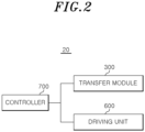
- the transfer module 300 may move the cutting module 200 along the longitudinal direction.
- the transfer module 300 may move the cutting module 200 in the longitudinal direction so that the cover film 12 is cut while the pressing module 400 presses the chamber 11 of the container 10.
- the transfer module 300 may move the cutting module 200 to the front side so that the cover film 12 is cut while the pressing module 400 presses the cover film 12 of the container 10.
- the transfer module 300 may move the cutting module 200 to the rear side while the pressing module 400 is spaced apart from the cover film 12 of the container 10.
- the transfer module 300 may include one or more of a hydraulic cylinder, an LM guide, and a ball screw motor to move the cutting module 200.
- the transfer module 300 may be coupled to at least one of the pressing module 400 and the base frame 100.
- the pressing module 400 may press both lateral portions of the container 10.
- the pressing module 400 may press downward the chambers 11 located in both lateral portions of the container 10.
- the container 10 may be the container 10 including the plurality of chambers 11 in the transverse direction.
- the chambers 11 located in both lateral portions may be the chambers 11 located in both lateral portions in the transverse direction of the container 10.
- the pressing module 400 may be coupled to the base frame 100 and may be movable in the vertical direction on the base frame 100.
- the pressing module 400 may include a pressing frame 410, a pressing member 420, and a pressing supporter 430.
- the pressing frame 410 may be supported from the pressing supporter 430, and the pressing frame 410 may support the pressing member 420.
- the pressing frame 410 together with the pressing supporter 430 may be relatively moved up and down with respect to the base frame 100.
- the pressing frame 410 may support a plurality of pressing members 420, and the pressing frame 410 may be configured to be movable in the vertical direction on the base frame 100.
- the pressing frame 410 may have a '[' shape so that both end portions of the pressing frame 410 is spaced apart from each other in the transverse direction.
- the pressing frame 410 is described as being supported from the pressing supporter 430, but this is only an example, and the pressing frame 410 may be movably coupled to the base frame 100.
- the pressing member 420 may press downward an upper portion of the cover film 12.
- the pressing member 420 may be provided as a plurality of pressing members 420, and the plurality of pressing members 420 may be spaced apart from each other along the transverse direction.
- the plurality of pressing members 420 may be configured to press the cover film 12 attached to the chambers 11 located in both lateral portion of the container 10 when the pressing frame 410 moves down.
- the pressing member 420 may extend along the longitudinal direction where the cutting module 200 is moved, and the pressing member 420 may have a flat shape. In this case, the pressing member 420 may press the upper portion of the cover film 12 while being in surface contact with the upper portion of the cover film 12.
- the plurality of pressing members 420 may be placed outward from the cutting mean 220, which is located at an outermost side, among the plurality of cutting means 220 in the transverse direction.
- the plurality of pressing members 420 may be placed inward from an edge of the chamber 11, which is located at an outermost side, among the plurality of chambers 11 in the transverse direction.
- the plurality of pressing members 420 may be placed further outward than a center of the chamber 11 which is located at the outermost side in the transverse direction. In this case, when the plurality of pressing members 420 press the cover film 12, the cover film 12 may be spread flat.
- the pressing supporter 430 may be supported from the base frame 100, and the pressing supporter 430 may support the pressing frame 410.
- the pressing supporter 430 may be coupled to the base frame 100 and may be movable in the vertical direction.
- the pressing supporter 430 may support the transfer module 300. For example, the pressing supporter 430 together with the cutting module 200 and the transfer module 300 may be moved up and down.
- the guide unit 500 may guide a movement of the base frame 100.
- the guide unit 500 may include a guide member 510 and a moving member 520.
- the guide member 510 may extend in the transverse direction, and the guide member 510 may guide the moving member 520 in the transverse direction.
- the guide member 510 may be provided as a rail shape so that the moving member 520 is supported from and is slid on the guide member 510.
- the base frame 100 may be supported from the moving member 520, and the base frame 100 may be moved by the moving member 520 in the transverse direction.
- the driving unit 600 may move the moving member 520 on the guide member 510 in the transverse direction. In addition, the driving unit 600 may move the pressing module 400 on the base frame 100 in the vertical direction.
- the driving unit 600 may include a plurality of actuators.
- the controller 700 may control an operation of the cutting module 200, the transfer module 300, and the pressing module 400. In addition, the controller 700 may control an operation of the driving unit 600.
- the controller 700 may be implemented by a computing device including a microprocessor, a measuring device such as a sensor, etc., and a memory, and since an implementation method of the controller 700 is obvious to those skilled in the art, a more detailed description is omitted.
- the film cutting device 20 may cut the cover film 12 of the container 10.
- the pressing supporter 430 may be moved down so that the pressing member 420 presses the upper portion of the cover film 12.
- the transfer module 300 may move the cutting module 200 so that the cutting module 200 is moved from the rear side of the container 10 toward the front side of the container 104.
- the cutting mean 220 when the cutting module 200 is placed in the rear side of the container 10, the cutting mean 220 may be placed in the first position, and the cutting mean 220 may be moved toward the front side while being placed in the first position.
- the cutting blade 222 cut a part of the rear end of the cover film 12 while moving forward, and then cut the cover film 12 between adjacent chambers 11.
- the cutting blade 222 cuts the rear end of the cover film 12 in an area that is not placed directly on the container 10. In this case, the cutting blade 222 cuts the cover film 12 without an interference from the chamber 11 in a position spaced apart from an edge of the chamber 11.
- the cutting blade 222 may cut the cover film 12 placed in an upper side of the container 10.
- the inclined surface 222b rises along the upper end of the chamber 11, and the inclined surface 222b is supported from the upper end of the chamber 11.
- the cutting blade 222 rotates around the rotation axis while being supported from the upper end of the chamber 11.
- the cutting edge 222a passes between a plurality of adjacent chambers 11 and cuts the cover film 12.
- the cutting blade 222 is rotated by being in contact with the upper end of the chamber 11 after the cutting blade 222 cuts a part of the rear end of the cover film 12.
- the cutting blade 222 is moved forward and passes between the plurality of adjacent chambers 11, the cutting mean 220 is moved down with respect to the supporter 210 by the restoring force of the elastic member 230.
- the cover film 12 is cut by the plurality of cutting means 220, the chamber 11 may be separated from each other.
- cover film 12 seals the plurality of chambers 11
- an upper portion of a gap between the plurality of chambers 11 sealed with the cover film 12 becomes narrower due to a heat shrinkage of the cover film 12, and a lower portion, which is opposite to the upper portion, of the gap becomes wider.
- the cover film 12 may be bent.
- the film cutting device 20 has an effect capable of evenly cutting the cover film 12 into multiple pieces.
- the plurality of cutting means 220 is configured to be independently movable up on the supporter 210, and there is an effect that may prevent the cover film 12 from being cut unevenly due to height differences between the chambers 11.
- the cutting blade 222 may rotate freely and is provided in a circular shape, there is an effect that may prevent the cutting blade 222 from being damaged when the cutting blade 222 cuts the cover film 12.
- the method S10 may cut the cover film 12 sealing the container 10.
- the cover film 12 of the container 10 is cut by using the film cutting device 20.
- the method S10 may include a preparation step S100, a pressing step S200, and a cutting step S300.
- the preparation step S 100 may prepare the container 10 so that the film cutting device 20 is positioned adj acent to the container 10 where the plurality of chambers 11 are sealed with the cover film 12.
- the film cutting device 20 may be spaced apart from the container 10, and the plurality of cutting means 220 may be placed in the first position.
- the pressing step S200 may press the container 10 by moving down the pressing module 400 .
- the pressing supporter 430 moves down along the base frame 100, and the pressing frame 410 and the pressing member 420 which are supported from the pressing supporter 430 are moved down together with the pressing supporter 430.
- the plurality of pressing members 420 may move down to pressurize the cover film 12 attached to the chambers 11, which are located in both lateral portions of the container 10 , among the plurality of chambers 11.
- the bent cover film 12 may be spread flat by the pressing member 420 before the pressing member 420 pressurize the container 10.
- the chambers 11 located in both lateral portions may be the chambers 11 located in both lateral portions of the container 10 in the transverse direction.
- the cutting step S300 may cut the cover film 12 attached to the container 10 by moving the cutting module 200 by the transfer module 300.
- the cutting module 200 may cut the cover film 12 while moving from the rear side of the container 10 toward the front side of the container 10.
- the transfer module 300 may cut the cover film 12 attached to the container 10 by moving the cutting module 200 between the plurality of pressing members 420.
- the cutting step S300 may be performed after the pressing step S200.
- the cutting step S300 may include a first cutting step S310 and a second cutting step S320.
- the cutting module 200 may cut a part of the rear end of the cover film 12. For example, when a size of the cover film 12 is greater than a size of the upper portion of the plurality of chambers 11, an edge of the cover film 12 is placed outside of an edge of the chamber 11. In this case, the cutting blade 222 cuts the rear end of the cover film 12 in a position spaced apart from the edge of the chamber 11 without an interference from the chamber 11. In addition, in the first cutting step S310, the cutting blade 222 moves while being placed in the first position, and cuts the cover film 12 while a height of the cutting blade 222 is maintained.
- the cutting module 200 may cut the cover film 12 between the plurality of chambers 11.
- the cutting blade 222 in the second cutting step S320 may move higher than the cutting blade 222 in the first cutting step S310, and may be rotated by being in contact with the upper end of the chamber 11.
- the inclined surface 222b of the cutting blade 222 rises along the upper end of the chamber 11, and is rotated while being supported from the upper end of the chamber 11.
- the cutting edge 222a moves between adjacent chambers 11 and cuts the cover film 12.
- the cutting frame 221 also rise toward the supporter 210 due to the rise of the cutting blade 222.
- the cutting mean 220 moves down to the first position by the elastic member 230.
Landscapes
- Engineering & Computer Science (AREA)
- Mechanical Engineering (AREA)
- Life Sciences & Earth Sciences (AREA)
- Forests & Forestry (AREA)
- Closing Of Containers (AREA)
Abstract
Description
- Embodiments relate generally to a film cutting device and a method of cutting a cover film of a container using film cutting device.
- Recently, as people's life expectancy has increased and an interest in health has increased, a demand for a genetic analysis, a base sequence analysis, a disease diagnosis, etc. has increased. In general, in order to analyze a genetic information of nucleic acids for a purpose of the genetic analysis, the base sequence analysis, the disease diagnosis, etc., the nucleic acids are extracted from biological samples and analyzed.
- A sample preparation process such as a nucleic acid extraction is mainly performed using an automated liquid handling device, and reagents used for the nucleic acid extraction are mainly provided using a cartridge-type container.
- A plurality of chambers capable of accommodating the reagent used for the nucleic acid extraction are formed in a container for the nucleic acid extraction, and a reagent used for each stage of the nucleic acid extraction is accommodated in each of the plurality of chambers. In addition, when the reagent for the nucleic acid extraction is accommodated in each of the plurality of chambers, the plurality of chambers are sealed with a film, etc. to prevent the reagent for the nucleic acid extraction from leaking. After each of the plurality of chambers is sealed, the container is provided to a user, and the container is opened and used just before being mounted on the liquid handling device.
- The reagents for the nucleic acid extraction included in each of the plurality of chambers of the container for the nucleic acid extraction may be exhausted at different rates depending on the user's extraction protocol. Therefore, each of the plurality of chambers of the container for the nucleic acid extraction may be configured to be separable so that only the exhausted chamber may be replaced. To this end, it is preferable that the container is manufactured so that the film sealing each of the plurality of chambers may be individually removed. However, if the plurality of chambers are individually sealed during a process of sealing the container, a sealing degree of the film may be different for each of the plurality of chambers. In this case, each of the plurality of chambers have a different sealing state, and a difference in the sealing degree of between the chambers may occur. In addition, if the plurality of chambers are individually sealed, it takes a lot of time to seal different films in each of the plurality of chambers. In this case, a sealing process becomes complicated, and a production efficiency is decreased.
- Accordingly, a method has been recently developed for manufacturing a plurality of containers sealed with a film by sealing the plurality of chambers of the container with a single film and then cutting the single film. However, when the plurality of chambers are sealed with the single film, an upper portion of a gap between the plurality of chambers sealed with the single film becomes narrower due to a heat shrinkage of the single film, and a lower portion, which is opposite to the upper portion, of the gap becomes wider. In this case, it is difficult to cut the single film sealing the plurality of chambers, and the single film is not cut precisely.
- Therefore, there is a need for a device capable of precisely cutting the single film sealing the plurality of chambers while simplifying the sealing process and improving a production efficiency by sealing the plurality of chambers with the single film and then cutting the single film.
- Embodiments provide a film cutting device capable of improving a production efficiency by simplifying a sealing process as the single film is cut after a plurality of chambers are sealed with a single film.
- Embodiments provide a film cutting device capable of precisely cutting the single film sealing the plurality of chambers.
- According to embodiments of the present disclosure, a film cutting device for cutting a cover film attached to a container including a plurality of chambers that are detachably connected to each other includes a base frame, a pressing module, a transfer module, and a cutting module. The pressing module is coupled to the base frame to be movable in a vertical direction, and is configured to move down and press downward the chambers located in both lateral portions of the container. The transfer module is coupled to at least one of the pressing module and the base frame. The cutting module is coupled to transfer module. The cutting module includes a plurality of cutting means capable of cutting the cover film attached to the container, and the transfer module is configured to move the cutting module in a longitudinal direction so that the cover film is cut while the pressing module presses the chamber of the container.
- In embodiments, the plurality of chambers may be connected to each other so that the plurality of chambers are arranged in a transverse direction.
- In embodiments, the cutting module may further include a supporter supporting the plurality of cutting means. Each of the plurality of cutting means may include a cutting frame supported from the supporter to be able to move up and down with respect to the supporter and a cutting blade supported from the cutting frame.
- In embodiments, the plurality of cutting means may be spaced apart from each other and may be supported from the supporter so that the plurality of cutting means are independently move up and down relative to each other.
- In embodiments, the cutting module may further include a plurality of elastic member providing a restoring force to the cutting frame so that the cutting blade is pressed toward the container.
- In embodiments, one side of the elastic member may be supported from the supporter, and other side of the elastic member may be supported from the cutting frame.
- In embodiments, a stopper may be provided to at least one of the cutting frame and the supporter, and the stopper may prevent the cutting frame from being separated from the supporter.
- In embodiments, the stopper may be protruded upward from the cutting frame, and may be supported from the supporter when the cutting frame is relatively moved down with respect to the supporter.
- In embodiments, the cutting blade may be supported from the cutting frame so that the cutting blade is rotatable.
- In embodiments, the cutting module may be moved forward so that the cover film is cut from a rear end of the cover film, and the cutting blade may move up more when cutting the cover film between the plurality of chambers than when cutting the rear end of the cover film.
- In embodiments, while the cutting module is moved forward, the cutting blade may cut a part of the rear end of the cover film and may be rotated by being in contact with an upper end of the chamber.
- In embodiments, the cutting blade may include a cutting edge provided at an end of the cutting blade and an inclined surface extending from the cutting edge toward a rotation axis of the cutting blade. The inclined surface may be inclined with respect to a direction that is perpendicular to a direction of the rotation axis. When the cutting edge cuts the cover film, the inclined surface may be in contact with the upper end of the chamber.
- In embodiments, the cutting blade may have a circular shape.
- In embodiments, the pressing module may include a plurality of pressing members and a pressing frame. The plurality of pressing members may be spaced apart from each other along a transverse direction of the cutting means, and may be capable of pressing an upper portion of the cover film. The pressing frame may support the plurality of pressing members, and may be configured to be movable in the vertical direction on the base frame. The plurality of pressing members may press the cover film attached to the chambers located in both lateral portions of the container, when the pressing frame moves down.
- In embodiments, the plurality of cutting means may be spaced apart from each other by a predetermined distance between the plurality of pressing members so that each of the cutting blades is located between the chambers.
- In embodiments, the plurality of pressing members may extend along the longitudinal direction, and each of the plurality of pressing members may have a flat shape.
- In embodiments, the plurality of chambers may be arranged in a transverse direction, and the cutting blade may be configured to cut the cover film with a part of the cutting blade inserted between the plurality of chambers.
- According to embodiments of the present disclosure, a method of cutting a cover film of a container includes (a) a preparation step of positioning a container in a film cutting device, (b) a pressing step of pressing the chambers located in both lateral portions of the container by moving down the pressing module, and (c) a cutting step of cover film attached to the container after the cutting module is moved by the transfer module. The container includes a plurality of chambers that are detachably connected to each other, and the film cutting device include a base frame, a pressing module, a transfer module, and a cutting module. The pressing module is coupled to the base frame to be movable in a vertical direction, and is configured to move down and press downward the chambers located in both lateral portions of the container. The transfer module is coupled to at least one of the pressing module and the base frame. The cutting module is coupled to transfer module. The cutting module includes a plurality of cutting means capable of cutting the cover film attached to the container, and the transfer module is configured to move the cutting module in a longitudinal direction so that the cover film is cut while the pressing module presses the chamber of the container.
- In embodiments, (c) the cutting step may be performed after (b) the pressing step.
- In embodiments, (c) the cutting step may include a first cutting step where the cutting module cuts a rear end of the cover film and a second cutting step where the cutting module cuts the cover film between the plurality of chambers. The cutting module may be moved forward so that the cover film is cut from the rear end of the cover film, and may include a cutting blade. The cutting blade may move up more in the second cutting step than the first cutting step.
- In embodiments, the cutting blade may be spaced apart from the chamber in the first cutting step, and may be rotated by being in contact with an upper end of the chamber in the second cutting step.
- In embodiments, the pressing module may include a plurality of pressing members spaced apart from each other along a transverse direction of the cutting means, and the container may include a plurality of chambers arranged in the transverse direction. In (b) the pressing step, the plurality of pressing members may press the cover film attached to chambers, which is located in both lateral portions of the container, among the plurality of chambers by moving down the plurality of pressing members.
- In embodiments, in (c) the cutting step, the transfer module may move the cutting module between the plurality of pressing members, and may cut the cover film attached to the container.
- In the film cutting device according to the embodiments of the present disclosure, as a single film is cut after the plurality of chambers are sealed with the single film, a process may be simplified, and a production efficiency is improved.
- In addition, the film cutting device according to the embodiments of the present disclosure may precisely cut a film sealing the plurality of chambers.
- Embodiments can be understood in more detail from the following description taken in conjunction with the accompanying drawings.
-
FIG. 1 is a perspective view illustrating a cover film cutting system according to embodiments of a present disclosure. -
FIG. 2 is a block diagram conceptually illustrating a transfer module, a diving unit, and a controller, and of a film cutting device according to embodiments of a present disclosure. -
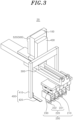
FIG. 3 is a perspective view illustrating the film cutting device ofFIG. 1 . -
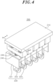
FIG. 4 is a perspective view illustrating a cutting module ofFIG. 1 . -
FIG. 5 is a cross-sectional view illustrating line I-I' ofFIG. 4 . -
FIG. 6 is a rear view and a partially enlarged view ofFIG. 4 . -
FIG. 7 is a partially perspective view illustrating the film cutting device and a cartridge ofFIG. 1 . -
FIG. 8 is a side view ofFIG. 7 . -
FIG. 9 is a rear view ofFIG. 7 . -
FIG. 10 is a diagram illustrating a state where a cutting mean rises with respect to a supporter ofFIG. 8 . -
FIG. 11 is a rear view and a partially enlarged view ofFIG. 10 . -
FIG. 12 is a flow chart illustrating a method of cutting a cover film of a container according to embodiments of a present disclosure. -
FIG. 13 is a flow chart sequentially illustrating a cutting step ofFIG. 12 . - Hereinafter, specific embodiments for implementing a spirit of the present disclosure will be described in detail with reference to the drawings.
- In describing the present disclosure, detailed descriptions of known configurations or functions may be omitted to clarify the present disclosure.
- When an element is referred to as being 'connected' to, 'supported' by, or 'supplied' to another element, it should be understood that the element may be directly connected to, supported by, or, supplied to another element, but that other elements may exist in the middle.
- The terms used in the present specification are only used for describing specific embodiments, and are not intended to limit the present disclosure. Singular expressions include plural expressions unless the context clearly indicates otherwise.
- Terms including ordinal numbers, such as first and second, may be used for describing various elements, but the corresponding elements are not limited by these terms. These terms are only used for the purpose of distinguishing one element from another element.
- In the present specification, it is to be understood that the terms such as "including" are intended to indicate the existence of the certain features, areas, integers, steps, actions, elements, combinations, and/or groups thereof disclosed in the specification, and are not intended to preclude the possibility that one or more other certain features, areas, integers, steps, actions, elements, combinations, and/or groups thereof may exist or may be added.
- A longitudinal direction, a transverse direction, and a vertical direction used in the present specification mean directions that are perpendicular to each other. That is, each of the directions is orthogonal to each other. The longitudinal direction, the transverse direction, and the vertical direction used in the present specification are similar to the Cartesian coordinate system that is generally used to define three-dimensional directions. The expressions of directions such as the longitudinal direction, the transverse direction, and the vertical direction in the present specification are described based on the drawings and may be differently expressed if the direction of the corresponding object changes. In other words, these directions may be interchangeably used when referring to the three-dimensional directions of components. Meanwhile, the longitudinal direction, the transverse direction, and the vertical direction used in the present specification may be the direction of the coordinate axis shown in
FIG. 1 . For example, the longitudinal direction in the present specification may be a front-back direction of the coordinate axis shown inFIG. 1 . In addition, the transverse direction in the present specification may be a left-right direction of the coordinate axis shown inFIG. 1 . Further, the vertical direction in the present specification may be an up-down direction of the coordinate axis shown inFIG. 1 . - Hereinafter, a specific configuration of a cover
film cutting system 1 according to embodiments of the present disclosure will be described with reference to the drawings. - Referring to
FIG. 1 , the coverfilm cutting system 1 according to embodiments of the present disclosure may include acontainer 10 and afilm cutting device 20. - The
container 10 may accommodate a reagent for a nucleic acid extraction. For example, thecontainer 10 may be a cartridge. In addition, thecontainer 10 may be transported while accommodating the nucleic acid extraction reagent. Thecontainer 10 may include achamber 11 and acover film 12. - The
chamber 11 may accommodate the reagent for the nucleic acid extraction, and may include a plurality ofchambers 11. The plurality ofchambers 11 may be connected to each other so that the plurality ofchambers 11 are arranged in a transverse direction, and the plurality ofchambers 11 may be detachably connected to each other. In addition, the plurality ofchambers 11 may be sealed with thecover film 12 so that the reagent for the nucleic acid extraction accommodated in an inside of each of the plurality ofchambers 11 is not leaked to an outside. For example, the reagent for the nucleic acid extraction accommodated in thechamber 11 refers to a reagent used to extract a nucleic acid from a sample. The reagent for the nucleic acid extraction may be separately accommodated in each of the plurality ofchambers 11. For example, the reagent for the nucleic acid extraction may include one or more of a lysis buffer that lyses cells in the sample to expose the nucleic acid, a binding buffer that combines the exposed nucleic acid molecule with a solid particle, a washing buffer that is not substantially affected in the combination of the solid particle and the nucleic acid molecule, and an elution buffer that separates the nucleic acid molecule from the solid particles. - In the present specification, the term "sample" may include a biological sample (e.g., cells, tissues, and fluids from biological sources) and a non-biological sample (e.g., food, water, and soil). In addition, the biological sample may include viruses, bacteria, tissues, cells, blood (e.g., whole blood, plasma, and serum), lymph, bone marrow fluid, saliva, sputum, swabs, aspirations, milk, urine, feces, eye fluid, semen, brain extracts, spinal fluid, joint fluid, thymus fluid, bronchial washings, ascites, and amniotic fluid.
- The
cover film 12 may seal the plurality ofchambers 11. For example, thecover film 12 may be adhered to an upper portion of each of the plurality ofchambers 11 to seal the plurality ofchambers 11, so that the inside of each of the plurality ofchambers 11 may be blocked from an outside of the plurality ofchambers 11. Here, a meaning of thecover film 12 sealing the plurality ofchambers 11 may be understood as a state where the inside and outside of the plurality ofchambers 11 are blocked by thecover film 12, so that there is not an inflow or outflow of a fluid into the plurality ofchambers 11. Thecover film 12 may be cut into multiple pieces by afilm cutting device 20. In addition, when thecover film 12 is cut by thefilm cutting device 20, the plurality ofchambers 11 may be separated from each other. - Referring to
FIGS. 1 and2 , thefilm cutting device 20 may cut thecover film 12. Thefilm cutting device 20 may include abase frame 100, acutting module 200, atransfer module 300, apressing module 400, aguide unit 500, adriving unit 600, and acontroller 700. - The
base frame 100 may support thecutting module 200, thetransfer module 300, and thepressing module 400. In addition, thebase frame 100 is movably supported on theguide unit 500, and a movement in the transverse direction may be guided by theguide unit 500. Thebase frame 100 together with thecutting module 200, thetransfer module 300, and thepressing module 400 may be moved in the transverse direction. For example, thebase frame 100 may be moved by the drivingunit 600. As another example, thebase frame 100 may be fixed and supported on theguide unit 500. If the position movement in the transverse direction of thebase frame 100 is used only for a purpose of a setting a reference position in the transverse direction of thecutting module 200 according to the a cutting position of thecontainer 10 and thecover film 12, thebase frame 100 moves when a device is initially set up, and there is no need to move in the transverse direction during a cutting process of thecover film 12 of thecontainer 10. Accordingly, thebase frame 100 may be fixed and supported on theguide unit 500 without moving by a power of thedriving unit 600. In this case, thecutting module 200 may cut thecover film 12 by moving in a longitudinal direction while a position of thecutting module 200 in the transverse direction is fixed. - Referring to
FIGS. 3 and4 , thecutting module 200 may cut thecover film 12 into multiple pieces. Thecutting module 200 may be moved along the longitudinal direction by thetransfer module 300. For example, thecutting module 200 may cut thecover film 12 while thecutting module 200 is moved from a rear end of thecontainer 10 to a front end of thecontainer 10. Thecutting module 200 may include asupporter 210, a cutting mean 220, anelastic member 230, and astopper 240. - The
supporter 210 may be configured to be movable so that the cutting mean 220 cuts thecover film 12. Thesupporter 210 may be supported from thetransfer module 300, and thesupporter 210 may be moved in the longitudinal direction by thetransfer module 300. For example, thesupporter 210 may be moved along the longitudinal direction while thesupporter 210 supports the cutting mean 220. In addition, thesupporter 210 may support a plurality of cutting means 220. The cutting mean 220 supported from thesupporter 210 may be configured to be relatively movable with respect to thesupporter 210. - Referring to
FIG. 5 , asupport hole 211 may be formed in thesupporter 210, and thestopper 240 may penetrate thesupport hole 211. Thesupport hole 211 may penetrate thesupporter 210 along a vertical direction. In addition, thestopper 240 may be inserted into thesupport hole 211, and a width of thesupport hole 211 may be greater than a diameter of thestopper 240. - A
guide hole 212 may be provided as a plurality of guide holes 212, and the plurality of guide holes 212 may be disposed in a front of thesupport hole 211 and a rear of thesupport hole 211. Theguide hole 212 may penetrate thesupporter 210 along the vertical direction. In addition, aguide pin 223, which will be described below, may be inserted into theguide hole 212. - The cutting mean 220 may cut the
cover film 12 of thecontainer 10. The cutting mean 220 may be supported from thesupporter 210 so that the cutting mean 220 is relatively movable in the vertical direction with respect to thesupporter 210. For example, the cutting mean 220 together with thesupporter 210 may be moved down while the cutting mean 220 is supported from thesupporter 210, and the cutting mean 220 may relatively rise with respect to thesupporter 210 when cutting thecover film 12. - The cutting mean 220 may be placed in a first position while not cutting the
cover film 12. Here, the first position of the cutting mean 220 may be a position where acutting blade 222, which will be described below, is furthest away from thesupporter 210, the first position of the cutting mean 220 means a relative position with respect to thesupporter 210. For example, when the cutting mean 220 is moved in the longitudinal direction without being moved up or being moved down with respect to thesupporter 210, the cutting mean 220 may be maintained in the first position. In addition, when the cutting mean 220 is placed in the first position, thestopper 240 may be maintained in a position while being caught on thesupporter 210, and theelastic member 230 may be decompressed. - In addition, the cutting mean 220 may be provided as a plurality of cutting means 220, and the plurality of cutting means 220 may be supported from the
supporter 210 so that the plurality of cutting means 220 are spaced apart from each other along the transverse direction. For example, the plurality of cutting means 220 may be arranged so that a plurality of cuttingblades 222 are spaced apart from each other along the transverse direction. In addition, the plurality of cutting means 220 may be spaced apart from each other by a predetermined distance in the transverse direction between a plurality of pressingmembers 420 . For example, the predetermined distance may be an interval where each of thecutting blades 222 is positioned between thechambers 11. In addition, for example, the predetermined distance may be a width of each of the chambers 11 (e.g., a size of each of the plurality ofchambers 11 in the transverse direction). In this way, thecover film 12 of thecontainer 10 may be cut for each chamber by thecutting blade 222, and when a user separates somechamber 11 from thecontainer 10, thechamber 11 may be separated while being sealed by thecover film 12. - The plurality of cutting means 220 may be simultaneously moved down in response to the moving down of the
supporter 210. In addition, the plurality of cutting means 220 may be independently moved in the vertical direction with respect to thesupporter 210. In other words, the plurality of cutting means 220 may be supported from thesupporter 210 so that each of the plurality of cutting means 220 are independently movable up and down. For example, the plurality of cutting means 220 may be independently moved in the vertical direction in response to a height difference of thecontainer 10 when cutting thecover film 12, and the plurality of cutting means 220 may cut thecover film 12 at different heights. In this case, although heights between the plurality ofchambers 11 are different, the plurality of cutting means 220 may cut thecover film 12 in response to the heights. - Meanwhile, each of the plurality of cutting means 220 may include a
cutting frame 221, thecutting blade 222, and theguide pin 223. - The cutting
frame 221 may be supported from thesupporter 210 so that thecutting frame 221 may be relatively movable in the vertical direction with respect to thesupporter 210. In addition, the cuttingframe 221 may rotatably support thecutting blade 222. For example, a bearing (not shown ) connected to thecutting blade 222 may be equipped in thecutting frame 221, and thecutting blade 222 may be supported from the cuttingframe 221 through the bearing. The cuttingframe 221 may be spaced apart from theadjacent cutting frame 221 in the transverse direction. In addition, the cuttingframe 221 may be supported from thesupporter 210 by thestopper 240, and thecutting frame 221 may be prevented from being separated from thesupporter 210 by thestopper 240. - Meanwhile, a movement in the vertical direction of the
cutting frame 221 may be guided by theguide pin 223. In addition, as the movement in the vertical direction of thecutting frame 221 is guided by theguide pin 223, the cuttingframe 221 may be moved up and down while maintaining a level without inclining toward front or rear side. In this case, as the cuttingframe 221 maintains the level, thecutting blade 222 may stably cut thecover film 12. - Referring
FIG. 6 , thecutting blade 222 may cut thecover film 12 into multiple pieces. Thecutting blade 222 may cut thecover film 12 by moving from the rear side of thecover film 12 to the front side of thecover film 12 in response to the movement of thecutting frame 221. In addition, thecutting blade 222 may be rotatably supported from the cuttingframe 221. That is, thecutting blade 222 may be supported from the cuttingframe 221 so as to be freely rotatable a rotation axis, which extends in one direction C, as a rotation center. For example, thecutting blade 222 may be rotated around the rotation axis by the bearing equipped in thecutting frame 221. In addition, thecutting blade 222 may be provided as a circular shape. Meanwhile, thecutting blade 222 may include acutting edge 222a and aninclined surface 222b. - The
cutting edge 222a may be formed in an end of thecutting blade 222, and thecutting edge 222a may extend along an edge of thecutting blade 222 in a circumferential direction. For example, thecutting edge 222a may be a blade portion that cuts thecover film 12 while being in contact with thecover film 12. In addition, thecutting edge 222a may have a predetermined thickness in the transverse direction. The thickness of thecutting edge 222a may be thinner than an interval betweenadjacent chambers 11. For example, while thecutting blade 222 moves to cut thecover film 12, a part of thecutting edge 222a may be inserted between theadjacent chambers 11, and thecutting blade 222 may be moved forward (or to the front side). In this case, thecover film 12 may be cut by thecutting edge 222a. - The
inclined surface 222b may be a portion of thecutting blade 222 other than thecutting edge 222a, and theinclined surface 222b may extend from thecutting edge 222a toward a rotation axis of thecutting blade 222. For example, theinclined surface 222b may be a portion that support thecutting edge 222a. In addition, theinclined surface 222b may be inclined with respect to a direction perpendicular to a direction the rotation axis. That is, theinclined surface 222b may be inclined with respect to a direction perpendicular to a direction where the rotation center of thecutting blade 222 is extended. - Meanwhile, the
inclined surface 222b may have a predetermined thickness in the transverse direction, and a thickness of theinclined surface 222b may be greater than a thickness of thecutting edge 222a. In addition, the thickness of theinclined surface 222b may be increased as theinclined surface 222b moves away from thecutting edge 222a. In other words, a thickness of a portion that is adjacent to thecutting edge 222a of theinclined surface 222b may be less than a thickness of a portion that is adjacent to the rotation axis of theinclined surface 222b. In this case, theinclined surface 222b may be supported from thechamber 11 while being inserted between thechambers 11 that is adjacent to a part of theinclined surface 222b. For example, when thecutting edge 222a of thecutting blade 222 is placed betweenadjacent chambers 11 to cut thecover film 12, theinclined surface 222b may rise along thechamber 11, and theinclined surface 222b may be supported from an upper end of thechamber 11. In this case, theinclined surface 222b passes between thechambers 11 adjacent to thecutting edge 222a, and theinclined surface 222b may be supported from the upper end of thechamber 11 and be moved to the front side while being cut thecover film 12. In other words, theinclined surface 222b may be configured to be in contact with the upper end of thechamber 11 when thecutting edge 222a cuts thecover film 12. - Meanwhile, the
cutting blade 222 together with the cuttingframe 221 may be moved up and down with respect to thesupporter 210. In addition, thecutting blade 222 may rise more when cutting thecover film 12 between thechambers 11 than when cutting the rear end of thecontainer 10. For example, when cutting the rear end of thecontainer 10, thecutting blade 222 may be moved forward while thecutting blade 222 is placed in the first position. In addition, when cutting thecover film 12 between thechambers 11, thecutting blade 222 may rise with theinclined surface 222b supported from the upper end of thechamber 11. In this case, thecutting blade 222 may be brought closer to thesupporter 210 than when thecutting blade 222 is placed in the first position. As another example, when thecutting blade 222 passes between thechambers 11, thecutting blade 222 may be moved down with respect to thesupporter 210, and thecutting blade 222 may be placed in the first position. In embodiments, thecutting module 200 may be moved forward so that thecover film 12 is cut from the rear end of thecover film 12, and thecutting blade 222 may be moved up more when cutting thecover film 12 between the plurality ofchambers 11 than when cutting the rear end of thecover film 12. - The
guide pin 223 may prevent thecutting frame 221 from being inclined toward the front or rear side. In other words, although thecutting frame 221 moves up and down with respect to thesupporter 210, theguide pin 223 may maintain an inclination of thecutting frame 221 with respect to thesupporter 210. Theguide pin 223 may be moved in response to thecutting frame 221 in the vertical direction while theguide pin 223 is inserted into theguide hole 212. In addition, theguide pin 223 may be provided as a plurality of guide pins 223, and the plurality of guide pins 223 may be disposed in a front of thestopper 240 and a rear of thestopper 240. For example, theguide pin 223 may be protruded upward from the cuttingframe 221. However, it is only an example, and theguide pin 223 may be protruded downward from thesupporter 210 and may be inserted into thecutting frame 221. - The
elastic member 230 may provide a restoring force to thecutting frame 221 so that thecutting blade 222 is pressed toward thecontainer 10. In addition, theelastic member 230 may provide the restoring force to the cutting mean 220 so that the cutting mean 220 moves in a direction toward the first position, when the plurality of cutting means 220 is displaced from the first position. One side of theelastic member 230 may be supported from a lower portion of thesupporter 210, and other side of theelastic member 230 may be supported from an upper portion of thecutting frame 221. In addition, theelastic member 230 may surround at least a part of thestopper 240. For example, theelastic member 230 may be more compressed when the cutting mean 220 is displaced from the first position than when the cutting mean 220 is placed in the first position. In this case, theelastic member 230 may provide the restoring force to the plurality of cutting means 220 so that the cutting mean 220 is moved to the first position. In other words, theelastic member 230 may provide a downward restoring force to the cutting mean 220. Theelastic member 230 may be provided as a plurality ofelastic members 230, and the plurality ofelastic members 230 may be provided to the plurality of cutting means 220, respectively. - The
stopper 240 may be selectively caught on thesupporter 210 so that thestopper 240 prevents thecutting frame 221 from being separated from thesupporter 210. In other words, as thestopper 240 is caught on thesupporter 210, thestopper 240 may prevent thecutting frame 221 from being excessively moved down with respect to thesupporter 210. For example, an end portion of one side of thestopper 240 may be supported from thesupporter 210, when the cutting mean 220 is moved down and is placed in the first position. In addition, when the cutting means 220 rises and is displaced from the first position, the end portion of one side of thestopper 240 may be spaced upward from thesupporter 210. A width of thestopper 240 may be less than a width of thesupport hole 211. In addition, thestopper 240 may be provided as at least one of thecutting frame 221 and thesupporter 210. For example, thestopper 240 may be protruded upward from the cuttingframe 221. In this case, thestopper 240 may be supported from thesupporter 210, when thecutting frame 221 is relatively moved down with respect to thesupporter 210. However, it is only an example, thestopper 240 may be protruded from thesupporter 210 and may be selectively caught on thecutting frame 221. - The
transfer module 300 may move thecutting module 200 along the longitudinal direction. Thetransfer module 300 may move thecutting module 200 in the longitudinal direction so that thecover film 12 is cut while thepressing module 400 presses thechamber 11 of thecontainer 10. For example, thetransfer module 300 may move thecutting module 200 to the front side so that thecover film 12 is cut while thepressing module 400 presses thecover film 12 of thecontainer 10. In addition, thetransfer module 300 may move thecutting module 200 to the rear side while thepressing module 400 is spaced apart from thecover film 12 of thecontainer 10. For example, thetransfer module 300 may include one or more of a hydraulic cylinder, an LM guide, and a ball screw motor to move thecutting module 200. Thetransfer module 300 may be coupled to at least one of thepressing module 400 and thebase frame 100. - Referring to
FIGS. 7 to 9 , as thepressing module 400 is moved down, thepressing module 400 may press both lateral portions of thecontainer 10. In other words, as thepressing module 400 is moved down, thepressing module 400 may press downward thechambers 11 located in both lateral portions of thecontainer 10. For example, thecontainer 10 may be thecontainer 10 including the plurality ofchambers 11 in the transverse direction. In this case, thechambers 11 located in both lateral portions may be thechambers 11 located in both lateral portions in the transverse direction of thecontainer 10. In addition, thepressing module 400 may be coupled to thebase frame 100 and may be movable in the vertical direction on thebase frame 100. Thepressing module 400 may include apressing frame 410, a pressingmember 420, and apressing supporter 430. - The
pressing frame 410 may be supported from thepressing supporter 430, and thepressing frame 410 may support thepressing member 420. Thepressing frame 410 together with thepressing supporter 430 may be relatively moved up and down with respect to thebase frame 100. Thepressing frame 410 may support a plurality of pressingmembers 420, and thepressing frame 410 may be configured to be movable in the vertical direction on thebase frame 100. For example, thepressing frame 410 may have a '[' shape so that both end portions of thepressing frame 410 is spaced apart from each other in the transverse direction. Meanwhile, in the present specification, thepressing frame 410 is described as being supported from thepressing supporter 430, but this is only an example, and thepressing frame 410 may be movably coupled to thebase frame 100. - The pressing
member 420 may press downward an upper portion of thecover film 12. The pressingmember 420 may be provided as a plurality of pressingmembers 420, and the plurality of pressingmembers 420 may be spaced apart from each other along the transverse direction. The plurality of pressingmembers 420 may be configured to press thecover film 12 attached to thechambers 11 located in both lateral portion of thecontainer 10 when thepressing frame 410 moves down. For example, the pressingmember 420 may extend along the longitudinal direction where thecutting module 200 is moved, and thepressing member 420 may have a flat shape. In this case, the pressingmember 420 may press the upper portion of thecover film 12 while being in surface contact with the upper portion of thecover film 12. - In addition, the plurality of pressing
members 420 may be placed outward from the cutting mean 220, which is located at an outermost side, among the plurality of cutting means 220 in the transverse direction. In addition, the plurality of pressingmembers 420 may be placed inward from an edge of thechamber 11, which is located at an outermost side, among the plurality ofchambers 11 in the transverse direction. As a more detailed example, the plurality of pressingmembers 420 may be placed further outward than a center of thechamber 11 which is located at the outermost side in the transverse direction. In this case, when the plurality of pressingmembers 420 press thecover film 12, thecover film 12 may be spread flat. - The
pressing supporter 430 may be supported from thebase frame 100, and thepressing supporter 430 may support thepressing frame 410. Thepressing supporter 430 may be coupled to thebase frame 100 and may be movable in the vertical direction. In addition, thepressing supporter 430 may support thetransfer module 300. For example, thepressing supporter 430 together with thecutting module 200 and thetransfer module 300 may be moved up and down. - The
guide unit 500 may guide a movement of thebase frame 100. Theguide unit 500 may include aguide member 510 and a movingmember 520. Theguide member 510 may extend in the transverse direction, and theguide member 510 may guide the movingmember 520 in the transverse direction. For example, theguide member 510 may be provided as a rail shape so that the movingmember 520 is supported from and is slid on theguide member 510. In addition, thebase frame 100 may be supported from the movingmember 520, and thebase frame 100 may be moved by the movingmember 520 in the transverse direction. - The driving
unit 600 may move the movingmember 520 on theguide member 510 in the transverse direction. In addition, the drivingunit 600 may move thepressing module 400 on thebase frame 100 in the vertical direction. The drivingunit 600 may include a plurality of actuators. - The
controller 700 may control an operation of thecutting module 200, thetransfer module 300, and thepressing module 400. In addition, thecontroller 700 may control an operation of thedriving unit 600. Thecontroller 700 may be implemented by a computing device including a microprocessor, a measuring device such as a sensor, etc., and a memory, and since an implementation method of thecontroller 700 is obvious to those skilled in the art, a more detailed description is omitted. - Hereinafter, an operation and an effect of the cover
film cutting system 1 according to embodiments of the present disclosure will be described. - The
film cutting device 20 may cut thecover film 12 of thecontainer 10. For example, as illustrated inFIG. 7 , when thecontainer 10 is placed in a predetermined position, thepressing supporter 430 may be moved down so that thepressing member 420 presses the upper portion of thecover film 12. When thepressing member 420 presses the upper portion of thecover film 12, thetransfer module 300 may move thecutting module 200 so that thecutting module 200 is moved from the rear side of thecontainer 10 toward the front side of the container 104. - Referring to
FIGS. 8 and9 , when thecutting module 200 is placed in the rear side of thecontainer 10, the cutting mean 220 may be placed in the first position, and the cutting mean 220 may be moved toward the front side while being placed in the first position. Thecutting blade 222 cut a part of the rear end of thecover film 12 while moving forward, and then cut thecover film 12 betweenadjacent chambers 11. For example, thecutting blade 222 cuts the rear end of thecover film 12 in an area that is not placed directly on thecontainer 10. In this case, thecutting blade 222 cuts thecover film 12 without an interference from thechamber 11 in a position spaced apart from an edge of thechamber 11. - Referring to
FIGS. 10 and11 , the cutting mean 220 is moved forward by thetransfer module 300, thecutting blade 222 may cut thecover film 12 placed in an upper side of thecontainer 10. For example, when thecutting blade 222 cuts thecover film 12 placed in the upper side of thecontainer 10, theinclined surface 222b rises along the upper end of thechamber 11, and theinclined surface 222b is supported from the upper end of thechamber 11. In this case, thecutting blade 222 rotates around the rotation axis while being supported from the upper end of thechamber 11. In addition, when thecutting blade 222 cuts thecover film 12 placed on the upper side of thecontainer 10, thecutting edge 222a passes between a plurality ofadjacent chambers 11 and cuts thecover film 12. In embodiments, while thecutting module 200 is moved forward, thecutting blade 222 is rotated by being in contact with the upper end of thechamber 11 after thecutting blade 222 cuts a part of the rear end of thecover film 12. - Afterwards, when the
cutting blade 222 is moved forward and passes between the plurality ofadjacent chambers 11, the cutting mean 220 is moved down with respect to thesupporter 210 by the restoring force of theelastic member 230. In addition, when thecover film 12 is cut by the plurality of cutting means 220, thechamber 11 may be separated from each other. - Meanwhile, when
cover film 12 seals the plurality ofchambers 11, an upper portion of a gap between the plurality ofchambers 11 sealed with thecover film 12 becomes narrower due to a heat shrinkage of thecover film 12, and a lower portion, which is opposite to the upper portion, of the gap becomes wider. Thecover film 12 may be bent. In this case, as thecutting module 200 cuts thecover film 12 while the plurality of pressingmembers 420 press both lateral portions of thecontainer 10 so that thecover film 12 becomes flat, thefilm cutting device 20 has an effect capable of evenly cutting thecover film 12 into multiple pieces. - In addition, the plurality of cutting means 220 is configured to be independently movable up on the
supporter 210, and there is an effect that may prevent thecover film 12 from being cut unevenly due to height differences between thechambers 11. - In addition, as the
cutting blade 222 may rotate freely and is provided in a circular shape, there is an effect that may prevent thecutting blade 222 from being damaged when thecutting blade 222 cuts thecover film 12. - Hereinafter, referring to
FIGS. 12 and 13 , a method S10 of cutting thecover film 12 of thecontainer 10 using thefilm cutting device 20 according to embodiments of a present disclosure will be described. The method S10 may cut thecover film 12 sealing thecontainer 10. For example, thecover film 12 of thecontainer 10 is cut by using thefilm cutting device 20. The method S10 may include a preparation step S100, a pressing step S200, and a cutting step S300. - The
preparation step S 100 may prepare thecontainer 10 so that thefilm cutting device 20 is positioned adj acent to thecontainer 10 where the plurality ofchambers 11 are sealed with thecover film 12. In thepreparation step S 100, thefilm cutting device 20 may be spaced apart from thecontainer 10, and the plurality of cutting means 220 may be placed in the first position. - The pressing step S200 may press the
container 10 by moving down thepressing module 400 . For example, in the pressurizing step S200, thepressing supporter 430 moves down along thebase frame 100, and thepressing frame 410 and thepressing member 420 which are supported from thepressing supporter 430 are moved down together with thepressing supporter 430. For example, the plurality of pressingmembers 420 may move down to pressurize thecover film 12 attached to thechambers 11, which are located in both lateral portions of thecontainer 10 , among the plurality ofchambers 11. In this case, thebent cover film 12 may be spread flat by the pressingmember 420 before thepressing member 420 pressurize thecontainer 10. Thechambers 11 located in both lateral portions may be thechambers 11 located in both lateral portions of thecontainer 10 in the transverse direction. - The cutting step S300 may cut the
cover film 12 attached to thecontainer 10 by moving thecutting module 200 by thetransfer module 300. In the cutting step S300, thecutting module 200 may cut thecover film 12 while moving from the rear side of thecontainer 10 toward the front side of thecontainer 10. Thetransfer module 300 may cut thecover film 12 attached to thecontainer 10 by moving thecutting module 200 between the plurality of pressingmembers 420. - In addition, the cutting step S300 may be performed after the pressing step S200. The cutting step S300 may include a first cutting step S310 and a second cutting step S320.
- In the first cutting step S310, the
cutting module 200 may cut a part of the rear end of thecover film 12. For example, when a size of thecover film 12 is greater than a size of the upper portion of the plurality ofchambers 11, an edge of thecover film 12 is placed outside of an edge of thechamber 11. In this case, thecutting blade 222 cuts the rear end of thecover film 12 in a position spaced apart from the edge of thechamber 11 without an interference from thechamber 11. In addition, in the first cutting step S310, thecutting blade 222 moves while being placed in the first position, and cuts thecover film 12 while a height of thecutting blade 222 is maintained. - In the second cutting step S320, the
cutting module 200 may cut thecover film 12 between the plurality ofchambers 11. In addition, thecutting blade 222 in the second cutting step S320 may move higher than thecutting blade 222 in the first cutting step S310, and may be rotated by being in contact with the upper end of thechamber 11. For example, when being changed from the first cutting step S310 to the second cutting step S320, theinclined surface 222b of thecutting blade 222 rises along the upper end of thechamber 11, and is rotated while being supported from the upper end of thechamber 11. In this case, thecutting edge 222a moves betweenadjacent chambers 11 and cuts thecover film 12. In addition, the cuttingframe 221 also rise toward thesupporter 210 due to the rise of thecutting blade 222. When the cutting step S300 is completed, the cutting mean 220 moves down to the first position by theelastic member 230. - Although the embodiments of the present disclosure have been described as specific embodiments, they are merely examples, and the present disclosure is not limited thereto, but should be interpreted to have the widest scope according to the technical idea disclosed in this specification. Those skilled in the art may implement a pattern of a shape not specified by combining/substituting the disclosed embodiments, but this also does not go beyond the scope of the present disclosure. In addition, those skilled in the art may easily change or modify the disclosed embodiments based on this specification, and it is clear that such changes or modifications also fall within the scope of the rights of the present disclosure.
- This patent application claims priority under Article 119(a) of the U.S. Patent Act (35 U.S.C § 119(a)) for
Korean Patent Application No. 10-2022-0025134 filed in Korea on Feb. 25, 2022
Claims (23)
- A film cutting device for cutting a cover film attached to a container including a plurality of chambers that are detachably connected to each other, the film cutting device comprising:a base frame;a pressing module coupled to the base frame to be movable in a vertical direction, the pressing module being configured to move down and press downward the chambers located in both lateral portions of the container;a transfer module coupled to at least one of the pressing module and the base frame; anda cutting module coupled to transfer module,wherein the cutting module includes a plurality of cutting means capable of cutting the cover film attached to the container, andwherein the transfer module is configured to move the cutting module in a longitudinal direction so that the cover film is cut while the pressing module presses the chamber of the container.
- The film cutting device of claim 1, wherein the plurality of chambers are connected to each other so that the plurality of chambers are arranged in a transverse direction.
- The film cutting device of claim 1, wherein the cutting module further includes a supporter supporting the plurality of cutting means, and
wherein each of the plurality of cutting means includes:a cutting frame supported from the supporter to be able to move up and down with respect to the supporter; anda cutting blade supported from the cutting frame. - The film cutting device of claim 3, wherein the plurality of cutting means are spaced apart from each other and are supported from the supporter so that the plurality of cutting means are independently move up and down relative to each other.
- The film cutting device of claim 3, wherein the cutting module further includes a plurality of elastic member providing a restoring force to the cutting frame so that the cutting blade is pressed toward the container.
- The film cutting device of claim 5, wherein one side of the elastic member is supported from the supporter, and other side of the elastic member is supported from the cutting frame.
- The film cutting device of claim 5, wherein a stopper is provided to at least one of the cutting frame and the supporter, and the stopper prevents the cutting frame from being separated from the supporter.
- The film cutting device of claim 7, wherein the stopper is protruded upward from the cutting frame, and the stopper is supported from the supporter when the cutting frame is relatively moved down with respect to the supporter.
- The film cutting device of claim 3, wherein the cutting blade is supported from the cutting frame so that the cutting blade is rotatable.
- The film cutting device of claim 9, wherein the cutting module is moved forward so that the cover film is cut from a rear end of the cover film, and
wherein the cutting blade moves up more when cutting the cover film between the plurality of chambers than when cutting the rear end of the cover film. - The film cutting device of claim 10, wherein while the cutting module is moved forward, the cutting blade cuts a part of the rear end of the cover film and is rotated by being in contact with an upper end of the chamber.
- The film cutting device of claim 11, wherein the cutting blade includes:a cutting edge provided at an end of the cutting blade; andan inclined surface extending from the cutting edge toward a rotation axis of the cutting blade,wherein the inclined surface is inclined with respect to a direction that is perpendicular to a direction of the rotation axis, andwherein when the cutting edge cuts the cover film, the inclined surface is in contact with the upper end of the chamber.
- The film cutting device of claim 9, wherein the cutting blade has a circular shape.
- The film cutting device of claim 3, wherein the pressing module includes:a plurality of pressing members are spaced apart from each other along a transverse direction of the cutting means, the plurality of pressing members being capable of pressing an upper portion of the cover film; anda pressing frame supporting the plurality of pressing members, the pressing frame being configured to be movable in the vertical direction on the base frame,wherein the plurality of pressing members presses the cover film attached to the chambers located in both lateral portions of the container, when the pressing frame moves down.
- The film cutting device of claim 14, wherein the plurality of cutting means are spaced apart from each other by a predetermined distance between the plurality of pressing members so that each of the cutting blades is located between the chambers.
- The film cutting device of claim 14, wherein the plurality of pressing members extend along the longitudinal direction, and each of the plurality of pressing members have a flat shape.
- The film cutting device of claim 3, wherein the plurality of chambers are arranged in a transverse direction, and the cutting blade is configured to cut the cover film with a part of the cutting blade inserted between the plurality of chambers.
- A method of cutting a cover film of a container, the method comprising:(a) a preparation step of positioning a container in a film cutting device;
wherein the container includes a plurality of chambers that are detachably connected to each other, and the film cutting device comprising:a base frame;a pressing module coupled to the base frame to be movable in a vertical direction, the pressing module being configured to move down and press downward the chambers located in both lateral portions of the container;a transfer module coupled to at least one of the pressing module and the base frame; anda cutting module coupled to transfer module,wherein the cutting module includes a plurality of cutting means capable of cutting the cover film attached to the container, andwherein the transfer module is configured to move the cutting module in a longitudinal direction so that the cover film is cut while the pressing module presses the chamber of the container,(b) a pressing step of pressing the chambers located in both lateral portions of the container by moving down the pressing module; and(c) a cutting step of cover film attached to the container after the cutting module is moved by the transfer module. - The method of claim 18, wherein (c) the cutting step is performed after (b) the pressing step.
- The method of claim 18, wherein (c) the cutting step includes:a first cutting step where the cutting module cuts a rear end of the cover film; anda second cutting step where the cutting module cuts the cover film between the plurality of chambers,wherein the cutting module is moved forward so that the cover film is cut from the rear end of the cover film, and the cutting module includes a cutting blade, andwherein the cutting blade moves up more in the second cutting step than the first cutting step.
- The method of claim 20, wherein the cutting blade is spaced apart from the chamber in the first cutting step, and the cutting blade is rotated by being in contact with an upper end of the chamber in the second cutting step.
- The method of claim 18, wherein the pressing module includes a plurality of pressing members spaced apart from each other along a transverse direction of the cutting means,wherein the container includes a plurality of chambers arranged in the transverse direction, andwherein in (b) the pressing step, the plurality of pressing members press the cover film attached to chambers, which is located in both lateral portions of the container, among the plurality of chambers by moving down the plurality of pressing members.
- The method of claim 22, wherein in (c) the cutting step, the transfer module moves the cutting module between the plurality of pressing members, and the transfer module cuts the cover film attached to the container.
Applications Claiming Priority (2)
| Application Number | Priority Date | Filing Date | Title |
|---|---|---|---|
| KR20220025134 | 2022-02-25 | ||
| PCT/KR2023/002508 WO2023163495A1 (en) | 2022-02-25 | 2023-02-22 | Film cutting apparatus and method for cutting container cover film using same |
Publications (2)
| Publication Number | Publication Date |
|---|---|
| EP4484308A1 true EP4484308A1 (en) | 2025-01-01 |
| EP4484308A4 EP4484308A4 (en) | 2026-01-21 |
Family
ID=87766416
Family Applications (1)
| Application Number | Title | Priority Date | Filing Date |
|---|---|---|---|
| EP23760369.1A Pending EP4484308A4 (en) | 2022-02-25 | 2023-02-22 | FILM CUTTING DEVICE AND METHOD FOR CUTTING A CONTAINER COVER FILM WITH IT |
Country Status (4)
| Country | Link |
|---|---|
| US (1) | US20250187774A1 (en) |
| EP (1) | EP4484308A4 (en) |
| KR (1) | KR20240138103A (en) |
| WO (1) | WO2023163495A1 (en) |
Family Cites Families (5)
| Publication number | Priority date | Publication date | Assignee | Title |
|---|---|---|---|---|
| JP5097493B2 (en) * | 2007-09-26 | 2012-12-12 | キユーピー株式会社 | Individual separation device for vertically and horizontally connected packages |
| EP3319876B1 (en) * | 2015-07-10 | 2024-08-28 | GEA Food Solutions Germany GmbH | Longitudinal cutter cassette |
| JP6527125B2 (en) * | 2016-11-29 | 2019-06-05 | Ckd株式会社 | Cutting device and blister packing machine |
| KR102079444B1 (en) * | 2018-06-05 | 2020-02-19 | 윤재중 | Apparatus for skin packaging |
| KR102344252B1 (en) * | 2020-01-30 | 2021-12-28 | 주식회사대한기계 | Film cutting device |
-
2023
- 2023-02-22 WO PCT/KR2023/002508 patent/WO2023163495A1/en not_active Ceased
- 2023-02-22 KR KR1020247028240A patent/KR20240138103A/en active Pending
- 2023-02-22 EP EP23760369.1A patent/EP4484308A4/en active Pending
- 2023-02-22 US US18/841,116 patent/US20250187774A1/en active Pending
Also Published As
| Publication number | Publication date |
|---|---|
| KR20240138103A (en) | 2024-09-20 |
| WO2023163495A1 (en) | 2023-08-31 |
| US20250187774A1 (en) | 2025-06-12 |
| EP4484308A4 (en) | 2026-01-21 |
Similar Documents
| Publication | Publication Date | Title |
|---|---|---|
| JP7581350B2 (en) | Slicable cassette with connector and embedding frame and method for preparing biopsy tissue samples - Patents.com | |
| EP1007937B1 (en) | Method and apparatus for automatically forming monolayers from particulate matter separated from fluid samples | |
| CN100518940C (en) | Cassette, embedding assembly and methods for handling tissue samples | |
| EP3335025B1 (en) | Sectionable cassette and embedding frame with tissue immobilizing separable lid, and methods for preparing biopsy tissue samples | |
| US9701957B2 (en) | Reagent holder, and kits containing same | |
| EP2214827B1 (en) | Multi-chambered tissue containment system for molecular and histology diagnostics | |
| EP2778654B1 (en) | Tissue cassette with biasing element | |
| CN204925140U (en) | System of full -automatic blood bank | |
| JP6117940B2 (en) | Specimen processing system and method for holding glass slide | |
| EP2918988B1 (en) | Block storage device and automatic thin-cutting device | |
| KR20210052586A (en) | Systems and methods for automated preparation of biological specimens | |
| US10335784B2 (en) | Device and method for dried fluid spot analysis | |
| US8597936B2 (en) | Device and method for the automated and reproducible production of cell or tissue samples that are to be analyzed and are arranged on object supports | |
| KR102721642B1 (en) | Method and apparatus for reducing the volume of a sample | |
| US11441112B2 (en) | Incubation device and system comprising incubation device and rocking platform | |
| US20250187774A1 (en) | Film cutting apparatus and method for cutting container cover film using same | |
| CN112098183B (en) | Automatic processing device and method for tissue sample dehydration embedding | |
| KR20220009548A (en) | All-in-one real time pcr apparatus | |
| EP3825005A1 (en) | Bucket insert for use in a centrifuge | |
| EP4455676A1 (en) | Seal inspecting device and container inspecting method | |
| JP7741143B2 (en) | Tissue chamber | |
| CN120333889A (en) | Seed cutting equipment | |
| CN224077357U (en) | Sample storage and processing device for gene detection | |
| US20210162349A1 (en) | Device for incubating and washing membrane/gel and method using thereof | |
| JP2004028737A (en) | Cassette for medical examinination |
Legal Events
| Date | Code | Title | Description |
|---|---|---|---|
| STAA | Information on the status of an ep patent application or granted ep patent |
Free format text: STATUS: THE INTERNATIONAL PUBLICATION HAS BEEN MADE |
|
| PUAI | Public reference made under article 153(3) epc to a published international application that has entered the european phase |
Free format text: ORIGINAL CODE: 0009012 |
|
| STAA | Information on the status of an ep patent application or granted ep patent |
Free format text: STATUS: REQUEST FOR EXAMINATION WAS MADE |
|
| 17P | Request for examination filed |
Effective date: 20240823 |
|
| AK | Designated contracting states |
Kind code of ref document: A1 Designated state(s): AL AT BE BG CH CY CZ DE DK EE ES FI FR GB GR HR HU IE IS IT LI LT LU LV MC ME MK MT NL NO PL PT RO RS SE SI SK SM TR |
|
| DAV | Request for validation of the european patent (deleted) | ||
| DAX | Request for extension of the european patent (deleted) | ||
| A4 | Supplementary search report drawn up and despatched |
Effective date: 20251223 |
|
| RIC1 | Information provided on ipc code assigned before grant |
Ipc: B65B 61/08 20060101AFI20251217BHEP Ipc: B26D 1/14 20060101ALI20251217BHEP Ipc: B26D 7/02 20060101ALI20251217BHEP Ipc: B26D 5/02 20060101ALI20251217BHEP Ipc: B26D 5/08 20060101ALI20251217BHEP |