JP7581350B2 - Slicable cassette with connector and embedding frame and method for preparing biopsy tissue samples - Patents.com - Google Patents
Slicable cassette with connector and embedding frame and method for preparing biopsy tissue samples - Patents.com Download PDFInfo
- Publication number
- JP7581350B2 JP7581350B2 JP2022527205A JP2022527205A JP7581350B2 JP 7581350 B2 JP7581350 B2 JP 7581350B2 JP 2022527205 A JP2022527205 A JP 2022527205A JP 2022527205 A JP2022527205 A JP 2022527205A JP 7581350 B2 JP7581350 B2 JP 7581350B2
- Authority
- JP
- Japan
- Prior art keywords
- frame
- cassette
- lid
- tissue
- connector
- Prior art date
- Legal status (The legal status is an assumption and is not a legal conclusion. Google has not performed a legal analysis and makes no representation as to the accuracy of the status listed.)
- Active
Links
Images


Classifications
-
- B—PERFORMING OPERATIONS; TRANSPORTING
- B01—PHYSICAL OR CHEMICAL PROCESSES OR APPARATUS IN GENERAL
- B01L—CHEMICAL OR PHYSICAL LABORATORY APPARATUS FOR GENERAL USE
- B01L9/00—Supporting devices; Holding devices
- B01L9/52—Supports specially adapted for flat sample carriers, e.g. for plates, slides, chips
-
- B—PERFORMING OPERATIONS; TRANSPORTING
- B01—PHYSICAL OR CHEMICAL PROCESSES OR APPARATUS IN GENERAL
- B01L—CHEMICAL OR PHYSICAL LABORATORY APPARATUS FOR GENERAL USE
- B01L3/00—Containers or dishes for laboratory use, e.g. laboratory glassware; Droppers
- B01L3/50—Containers for the purpose of retaining a material to be analysed, e.g. test tubes
- B01L3/508—Rigid containers without fluid transport within
- B01L3/5082—Test tubes per se
- B01L3/50825—Closing or opening means, corks, bungs
-
- B—PERFORMING OPERATIONS; TRANSPORTING
- B29—WORKING OF PLASTICS; WORKING OF SUBSTANCES IN A PLASTIC STATE IN GENERAL
- B29C—SHAPING OR JOINING OF PLASTICS; SHAPING OF MATERIAL IN A PLASTIC STATE, NOT OTHERWISE PROVIDED FOR; AFTER-TREATMENT OF THE SHAPED PRODUCTS, e.g. REPAIRING
- B29C45/00—Injection moulding, i.e. forcing the required volume of moulding material through a nozzle into a closed mould; Apparatus therefor
-
- G—PHYSICS
- G01—MEASURING; TESTING
- G01N—INVESTIGATING OR ANALYSING MATERIALS BY DETERMINING THEIR CHEMICAL OR PHYSICAL PROPERTIES
- G01N1/00—Sampling; Preparing specimens for investigation
-
- G—PHYSICS
- G01—MEASURING; TESTING
- G01N—INVESTIGATING OR ANALYSING MATERIALS BY DETERMINING THEIR CHEMICAL OR PHYSICAL PROPERTIES
- G01N1/00—Sampling; Preparing specimens for investigation
- G01N1/02—Devices for withdrawing samples
- G01N1/04—Devices for withdrawing samples in the solid state, e.g. by cutting
- G01N1/06—Devices for withdrawing samples in the solid state, e.g. by cutting providing a thin slice, e.g. microtome
-
- G—PHYSICS
- G01—MEASURING; TESTING
- G01N—INVESTIGATING OR ANALYSING MATERIALS BY DETERMINING THEIR CHEMICAL OR PHYSICAL PROPERTIES
- G01N1/00—Sampling; Preparing specimens for investigation
- G01N1/28—Preparing specimens for investigation including physical details of (bio-)chemical methods covered elsewhere, e.g. G01N33/50, C12Q
- G01N1/30—Staining; Impregnating ; Fixation; Dehydration; Multistep processes for preparing samples of tissue, cell or nucleic acid material and the like for analysis
- G01N1/31—Apparatus therefor
- G01N1/312—Apparatus therefor for samples mounted on planar substrates
-
- G—PHYSICS
- G01—MEASURING; TESTING
- G01N—INVESTIGATING OR ANALYSING MATERIALS BY DETERMINING THEIR CHEMICAL OR PHYSICAL PROPERTIES
- G01N1/00—Sampling; Preparing specimens for investigation
- G01N1/28—Preparing specimens for investigation including physical details of (bio-)chemical methods covered elsewhere, e.g. G01N33/50, C12Q
- G01N1/36—Embedding or analogous mounting of samples
-
- G—PHYSICS
- G01—MEASURING; TESTING
- G01N—INVESTIGATING OR ANALYSING MATERIALS BY DETERMINING THEIR CHEMICAL OR PHYSICAL PROPERTIES
- G01N33/00—Investigating or analysing materials by specific methods not covered by groups G01N1/00 - G01N31/00
- G01N33/48—Biological material, e.g. blood, urine; Haemocytometers
- G01N33/483—Physical analysis of biological material
- G01N33/4833—Physical analysis of biological material of solid biological material, e.g. tissue samples, cell cultures
-
- B—PERFORMING OPERATIONS; TRANSPORTING
- B01—PHYSICAL OR CHEMICAL PROCESSES OR APPARATUS IN GENERAL
- B01L—CHEMICAL OR PHYSICAL LABORATORY APPARATUS FOR GENERAL USE
- B01L2200/00—Solutions for specific problems relating to chemical or physical laboratory apparatus
- B01L2200/02—Adapting objects or devices to another
- B01L2200/025—Align devices or objects to ensure defined positions relative to each other
-
- B—PERFORMING OPERATIONS; TRANSPORTING
- B01—PHYSICAL OR CHEMICAL PROCESSES OR APPARATUS IN GENERAL
- B01L—CHEMICAL OR PHYSICAL LABORATORY APPARATUS FOR GENERAL USE
- B01L2300/00—Additional constructional details
- B01L2300/04—Closures and closing means
- B01L2300/041—Connecting closures to device or container
- B01L2300/043—Hinged closures
-
- B—PERFORMING OPERATIONS; TRANSPORTING
- B01—PHYSICAL OR CHEMICAL PROCESSES OR APPARATUS IN GENERAL
- B01L—CHEMICAL OR PHYSICAL LABORATORY APPARATUS FOR GENERAL USE
- B01L2300/00—Additional constructional details
- B01L2300/06—Auxiliary integrated devices, integrated components
- B01L2300/0609—Holders integrated in container to position an object
-
- G—PHYSICS
- G01—MEASURING; TESTING
- G01N—INVESTIGATING OR ANALYSING MATERIALS BY DETERMINING THEIR CHEMICAL OR PHYSICAL PROPERTIES
- G01N1/00—Sampling; Preparing specimens for investigation
- G01N1/28—Preparing specimens for investigation including physical details of (bio-)chemical methods covered elsewhere, e.g. G01N33/50, C12Q
- G01N1/36—Embedding or analogous mounting of samples
- G01N2001/368—Mounting multiple samples in one block, e.g. TMA [Tissue Microarrays]
Landscapes
- Health & Medical Sciences (AREA)
- Life Sciences & Earth Sciences (AREA)
- Chemical & Material Sciences (AREA)
- Physics & Mathematics (AREA)
- Analytical Chemistry (AREA)
- General Health & Medical Sciences (AREA)
- Engineering & Computer Science (AREA)
- Biochemistry (AREA)
- General Physics & Mathematics (AREA)
- Immunology (AREA)
- Pathology (AREA)
- Biomedical Technology (AREA)
- Molecular Biology (AREA)
- Hematology (AREA)
- Clinical Laboratory Science (AREA)
- Chemical Kinetics & Catalysis (AREA)
- Optics & Photonics (AREA)
- Biophysics (AREA)
- Urology & Nephrology (AREA)
- Food Science & Technology (AREA)
- Medicinal Chemistry (AREA)
- Manufacturing & Machinery (AREA)
- Mechanical Engineering (AREA)
- Sampling And Sample Adjustment (AREA)
Description
関連出願の相互参照
本出願は、その開示全体が参照により本明細書に組み込まれている、2019年11月12日に出願した米国特許出願第16/680,601号の優先権を主張するものである。
CROSS-REFERENCE TO RELATED APPLICATIONS This application claims priority to U.S. Patent Application No. 16/680,601, filed November 12, 2019, the disclosure of which is incorporated herein by reference in its entirety.
本発明は、一般に、病理解析のための組織試料を取り扱い、包埋するための支持体、より詳細には、1つまたは複数の組織試料と組織固定蓋(tissue immobilizing lid)を有する支持フレームとを受け入れることができるミクロトーム薄切可能支持体(microtome sectionable support)に関する。 The present invention relates generally to a support for handling and embedding tissue samples for pathological analysis, and more particularly to a microtome sectionable support capable of accepting one or more tissue samples and a support frame having a tissue immobilizing lid.
様々な組織疾病および病状を正確に診断するために、医療従事者は、患者の身体から組織の1つまたは複数の試料を取り出さなければならない。身体から組織を採取するこのプロセスは、生検と称されている。1つまたは複数の組織試料が取り出され、病理検査室に送られた後、組織は、組織に関連する1つまたは複数の病状を診断するために、ヒストテクニシャンにおよび最終的には、病理学者によって実施される一連の処置を経ることになる。本発明は、一般に、病理学者によって顕微鏡下で分析され得る1つまたは複数の組織試料をスライド内に準備するために通常はヒストテクニシャンによって実施される処置に関する。 To accurately diagnose various tissue diseases and conditions, medical personnel must remove one or more samples of tissue from a patient's body. This process of taking tissue from the body is called a biopsy. After one or more tissue samples are removed and sent to a pathology laboratory, the tissue will undergo a series of procedures performed by a histotechnician and ultimately a pathologist to diagnose one or more medical conditions associated with the tissue. The present invention generally relates to the procedures typically performed by a histotechnician to prepare one or more tissue samples in slides that can be analyzed under a microscope by a pathologist.
「試料」という用語は単数で、本明細書全体を通して使用されているが、この用語は、複数の「試料」を同様に包含するものとして理解されるべきである。組織試料が患者の身体から取り出された後、これは典型的には組織固定液を収容している試料容器内に載置され、次いで、容器は病理検査室に移送される。組織は、病理検査室内で「グロスイン」と称されるプロセスを経るが、このときに、ヒストテクニシャンは容器から組織試料を取り出し、典型的には、組織処理のために組織を適切なサイズに切断し、個別の試料を適切なサイズの小さいプラスチック製組織カセット内に載置し、追跡番号を各カセットに割り当てる。追跡番号の割り当ては、通常、カセットに追跡番号を印刷するか、またはその後カセットに貼られるラベルに印刷することによって行われる。次いで、これらの追跡番号は、検査室内で使用される追跡システム内に記録される。剥離物にすぎない場合もある、最小の組織試料のために、カセットは、側部と底部とに微細メッシュ開口部を備える。非常に小さい組織試料を伴う他の状況では、試料は、最小の組織試料が漏れるのを防ぐティーバッグに似たバッグ内に載置される。より大きい組織試料は、しかしながら、カセットの内側の組織試料よりも小さい、いくぶん大きいスロット付き開口部を有するカセット内に載置される。 Although the term "sample" is used throughout this specification in the singular, it should be understood to encompass the plural "samples" as well. After a tissue sample is removed from a patient's body, it is typically placed into a sample container containing a tissue fixative, and the container is then transported to a pathology laboratory. In the pathology laboratory, the tissue undergoes a process called "gross-in," during which a histotechnician removes the tissue sample from the container, typically cuts the tissue into appropriate sizes for tissue processing, places the individual samples into small plastic tissue cassettes of appropriate size, and assigns a tracking number to each cassette. Assignment of tracking numbers is typically done by printing the tracking numbers on the cassette or on a label that is then affixed to the cassette. These tracking numbers are then recorded in a tracking system used in the laboratory. For the smallest tissue samples, which may be no more than a peel, the cassettes are equipped with fine mesh openings on the sides and bottom. In other situations involving very small tissue samples, the sample is placed in a bag similar to a tea bag that prevents the smallest tissue samples from leaking. Larger tissue samples are placed in a cassette with a somewhat larger slotted opening, however, smaller than the tissue sample inside the cassette.
次いで、カセットは、ステンレス鋼製穿孔バスケット内に載置され、組織処理機に、多くの場合に一晩通される。この機械は、真空、熱、および液体試薬または化学薬品の組合せを使用して、組織内の間質液を取り除く。流体が組織試料から取り除かれた後、処理機は、組織試料を溶融パラフィン(すなわち、ワックス状)などの硬化性材料液中に浸し、組織内の間質液がパラフィンで置換されるようにする。次いで、ヒストテクニシャンは、機械からバスケットを取り出し、個別の組織カセットを取り出す。長年にわたって実践されてきた従来の処置では、ヒストテクニシャンは、各カセットから組織試料を個別に取り出す。ヒストテクニシャンは、組織のタイプに基づき、注意深く、組織試料をおおよそ組織カセットのサイズであり、部分的に溶融パラフィンで充填されるステンレス鋼製ベースモールド内に入れて向き付けなければならない。組織試料は、典型的には、鉗子を使用して、手作業でモールドの底部に押し付けられなければならない。そうしないと、ミクロトームで後から組織試料の適切な薄片を作ることができなくなる可能性がある。次いで、溶融パラフィンは、熱電クーラー(TEC)であってもよい、冷凍プレート上で急速冷却され、これにより、パラフィンを部分的固化させ、それによって組織試料をモールドの底部に適切な向きで押し付ける。 The cassette is then placed into a stainless steel perforated basket and run through a tissue processor, often overnight. This machine uses a combination of vacuum, heat, and liquid reagents or chemicals to remove the interstitial fluid within the tissue. After the fluid is removed from the tissue sample, the processor immerses the tissue sample in a hardenable liquid material such as molten paraffin (i.e., waxy), so that the interstitial fluid within the tissue is replaced with paraffin. The histotechnician then removes the basket from the machine and removes the individual tissue cassettes. In a traditional procedure that has been practiced for many years, the histotechnician removes the tissue samples from each cassette individually. Based on the type of tissue, the histotechnician must carefully orient the tissue samples into a stainless steel base mold that is roughly the size of the tissue cassette and is partially filled with molten paraffin. The tissue sample must be manually pressed against the bottom of the mold, typically using forceps. Failure to do so may prevent proper sectioning of the tissue sample later in the microtome. The molten paraffin is then rapidly cooled on a freezing plate, which may be a thermoelectric cooler (TEC), causing the paraffin to partially solidify, thereby pressing the tissue sample into the bottom of the mold in the proper orientation.
次いで、カセットは、ベースモールドの上に載置され、典型的にはパラフィン蝋でもある、包埋材料が、カセットの開かれた頂部を通してベースモールド内に注ぎ込まれる。カセットは、ミクロトーム内に装着し、ミクロトーム内の固化したパラフィンブロック(組織試料を含む)から削りくずまたは薄片を作るために、処置のこの時点において組織保持コンポーネントから固定具タイプのデバイスにその機能を変化させる。ベースモールドは溶融パラフィンのすべてが硬化するまで冷却され、ヒストテクニシャンがパラフィンおよび包埋組織のブロックからステンレス鋼製ベースモールドを取り出す。こうして、組織試料は、反対側にあるプラスチック製組織カセットとともに固形パラフィンの矩形ブロック内に包埋される。次いで、言及されているように、カセットは、ミクロトームのチャック内でホルダーまたは固定具として使用され得る。組織処理機の場合と同様に、包埋プロセスは、平均的なヒストテクニシャンが1時間当たり約40から60個のカセットを包埋組織のいくつかのブロックに分けて処理し得るバッチ方式で実行される。 The cassette is then placed on top of the base mold and the embedding material, which is also typically paraffin wax, is poured into the base mold through the open top of the cassette. The cassette is then loaded into the microtome, changing its function at this point in the procedure from a tissue-holding component to a fixture-type device in order to make shavings or sections from the solidified paraffin block (containing the tissue sample) in the microtome. The base mold is cooled until all of the molten paraffin has hardened, and the histotechnician removes the stainless steel base mold from the block of paraffin and embedded tissue. The tissue sample is now embedded in a rectangular block of solid paraffin with the plastic tissue cassette on the other side. As mentioned, the cassette may then be used as a holder or fixture in the chuck of the microtome. As with the tissue processor, the embedding process is carried out in a batch fashion where an average histotechnician may process about 40 to 60 cassettes per hour in blocks of embedded tissue.
次いで、包埋された組織試料の硬化したパラフィンのブロックは、顕微鏡用スライド上に載置できるように薄く切って極めて薄い切片にすることが容易である。ヒストテクニシャンは、包埋されたプラスチック製カセットを有するブロックの側部を受け入れるサイズを有するミクロトーム上のチャック内に包埋された組織ブロックを装着する。次いで、ヒストテクニシャンは、プラスチック製カセットの表面とは反対側に包埋されている組織試料を有するパラフィンブロックを薄く切ることを始めることができる。これにより、硬化したパラフィン内に包埋された組織の個別の薄片のリボンを形成する。ミクロトームの作用により、個別の薄片が適切になされたときにくっつき合い、その後、薄片のこれらの非常に薄いリボンは、水浴内に浮かべられ、ガラススライドが、注意深く薄片の下に載置される。次いで、各薄片は、中に包埋されている薄い薄切りされた組織試料とともに、顕微鏡用スライドの上に付着させられる。ヒストテクニシャンが組織試料から十分なスライドを得たときに、スライドは、自動染色機内に載置される。染色機は、一連の浸潤ステップを経て、スライドの異なる組織および細胞を異なる色で染色する。これは、病理学者が異なる構造を識別するのを助け、組織中に異常を見つけやすくする。染色処置が完了した後、スライドは、病理学者が分析のために顕微鏡下に載置できるようにカバースリップされ、用意される。 The hardened paraffin block with the embedded tissue sample is then easily sliced into very thin sections that can be placed on microscope slides. The histotechnician mounts the embedded tissue block in a chuck on the microtome that is sized to receive the side of the block with the embedded plastic cassette. The histotechnician can then begin slicing the paraffin block with the embedded tissue sample on the side opposite the surface of the plastic cassette. This creates ribbons of individual slices of tissue embedded in the hardened paraffin. The action of the microtome causes the individual slices to stick together when done properly, and then these very thin ribbons of slices are floated in a water bath and a glass slide is carefully placed underneath the slices. Each slice is then attached onto a microscope slide with the thin sliced tissue sample embedded within it. When the histotechnician has enough slides from the tissue sample, the slides are placed into an automatic stainer. The stainer goes through a series of infiltration steps to stain different tissues and cells on the slide with different colors. This helps the pathologist distinguish between different structures and makes it easier to spot abnormalities in the tissue. After the staining procedure is complete, the slide is coverslipped and prepared for the pathologist to place under the microscope for analysis.
上で示されている処置の要約に基づき、従来の組織試料の取り扱いおよび処理は、ヒストテクニシャンによって実行されるいくつかの手動ステップを伴う非常に労働集約的なプロセスであることは理解されるであろう。そのため、手根管症候群などの反復性のストレス障害がよく生じる。これは、組織試料包埋プロセスの場合に特に当てはまる。これらの複数の手作業および繰り返される組織取り扱いは、人間の誤りを生じる可能性を増大させ、さらに、病理学者による分析を行えるようにスライドに最終的に付着される組織試料が正確な診断を行う最適な状態および向きに置かれることを確実にするために、高度な訓練を受け、熟練したヒストテクニシャンを必要とする。 Based on the summary of procedures presented above, it will be appreciated that traditional tissue sample handling and processing is a highly labor-intensive process involving several manual steps performed by the histotechnician. As such, repetitive stress injuries such as carpal tunnel syndrome are common. This is especially true in the case of the tissue sample embedding process. These multiple manual steps and repeated tissue handling increase the potential for human error and further require highly trained and skilled histotechnicians to ensure that the tissue sample that is ultimately attached to the slide for analysis by the pathologist is in an optimal condition and orientation for accurate diagnosis.
米国特許第5,817,032号('032特許)、米国特許第7,156,814号、米国特許第7,179,424号、米国特許第7,722,810号、米国特許第7,776,274号、および米国特許第8,383,067号ならびに米国特許出願公開第2018/0156701号では、グロスイン、包埋、およびミクロトームもしくは薄切り処置の際に組織試料を保持する新しい方式を含む、この技術分野の様々な改善を開示している。'032特許、米国特許第7,156,814号、米国特許第7,179,424号、米国特許第7,722,810号、米国特許第7,776,274号、米国特許第8,383,067号、および米国特許出願公開第2018/0156701号は、参照により本明細書に完全に組み込まれている。たとえば、'032特許は、組織捕捉および支持デバイスに関するものであり、これはカセットであってよく、ミクロトームを使用してうまく薄切りされ得る。そのようなカセットが使用されるときに、組織試料は、カセット内に固定され、組織流体をパラフィンで置き換えるためのプロセスに通される。次いで、組織試料およびカセットは両方とも、顕微鏡用スライド上に後で装着するために同時に薄切りされる。組織試料は、組織処理機内で処理されたときからミクロトームで切断または薄切りされるときまでカセットから決して取り出されないので、取り扱い時間がかなり短縮される。さらに、人間の誤りまたは組織の損失の可能性も、別個の組織取り扱いステップがなくなるので、著しく低減される。'032特許および他の上記の組み込まれている特許権は、また、一般的に、プロセス全体を自動化するのに役立ち、新規性のある組織支持体(たとえば、カセット)と連動して、処置全体における取り扱いステップをさらに減らし、処置をより信頼性の高いものにすることができるさらなる改善を開示している。 Nos. 5,817,032 (the '032 patent), 7,156,814, 7,179,424, 7,722,810, 7,776,274, and 8,383,067, as well as U.S. Patent Application Publication No. 2018/0156701, disclose various improvements in this field, including new ways of holding tissue samples during grossing, embedding, and microtoming or slicing. The '032 patent, 7,156,814, 7,179,424, 7,722,810, 7,776,274, 8,383,067, and U.S. Patent Application Publication No. 2018/0156701 are incorporated herein by reference in their entireties. For example, the '032 patent is directed to a tissue capture and support device, which may be a cassette, that can be conveniently sliced using a microtome. When such a cassette is used, the tissue sample is fixed within the cassette and put through a process to replace the tissue fluid with paraffin. Both the tissue sample and the cassette are then simultaneously sliced for later mounting on a microscope slide. Because the tissue sample is never removed from the cassette from the time it is processed in the tissue processor until it is cut or sliced with the microtome, handling time is significantly reduced. Furthermore, the possibility of human error or tissue loss is also significantly reduced since a separate tissue handling step is eliminated. The '032 patent and the other above-mentioned incorporated patents also generally disclose further improvements that can help automate the entire process and, in conjunction with novel tissue supports (e.g., cassettes), further reduce handling steps in the overall procedure, making the procedure more reliable.
現行の処置の様々な短所および革新に対する制限が存在する。たとえば、カセットおよびフレームの外形の改善は、組織処理レトルト、および組織処理装置、包埋ステーション、プリンタ、およびミクロトームのための「入力デバイス」などの、組織病理実験機器の既存の制限によって制約される。これらのプロセスの多くは、ステップの自動化およびロボット取り扱いのためのシステムおよび機械と一体化され、革新に対する潜在的可能性をさらに制限する。それに加えて、材料に対するコスト、特に薄切可能カセットにおいて有用なフッ素重合体(FEP/PFA)薄切可能プラスチックに対するコストが、近年になって上昇してきている。各カセットは、薄切処置によって本質的に消費され、これが病変処置のコストに加わる。さらに、薄切可能FEP/PFA材料は剛性を有していないので、いくつかのコンポーネント(たとえば、カセット)に利用され得るが、他のコンポーネント(たとえば、フレーム)は、より硬いまたはより剛性の高い材料から作製され得る。 There are various shortcomings of current procedures and limitations to innovation. For example, improvements in cassette and frame geometry are constrained by existing limitations of histopathology laboratory equipment, such as tissue processing retorts and "input devices" for tissue processors, embedding stations, printers, and microtomes. Many of these processes are integrated with systems and machines for automation of steps and robotic handling, further limiting the potential for innovation. In addition, the cost of materials has risen in recent years, especially for fluoropolymer (FEP/PFA) sectionable plastics useful in sectionable cassettes. Each cassette is essentially consumed by the sectioning procedure, which adds to the cost of the lesion procedure. Furthermore, sectionable FEP/PFA material is not rigid and may be utilized for some components (e.g., cassettes), while other components (e.g., frames) may be made from harder or more rigid materials.
この分野では様々な進歩がなされたが、カセットおよび包埋フレームに関係する追加の改善、特に、より硬い材料から形成された他のコンポーネントに結合される比較的柔らかい材料(たとえば、薄切可能なプラスチック)から形成されたいくつかのコンポーネントを含むカセットおよびフレームアセンブリに対する必要性が存在する。 While various advances have been made in this field, a need exists for additional improvements related to cassettes and embedding frames, particularly cassette and frame assemblies that include some components formed from relatively soft materials (e.g., sectionable plastics) that are bonded to other components formed from harder materials.
一実施形態によれば、組織学的組織試料支持デバイスは、少なくとも1つの側壁と底壁とを備える陥凹部を有する組織カセットを備える。組織カセットは、ミクロトームでの薄切りに成功し得る第1の材料から形成され、組織を固定し、処理し、染色するために使用される溶媒および化学薬品による劣化に強い。デバイスは、底縁を含むフレームをさらに備え、フレームは第1の材料と異なる、また第1の材料よりも剛性が高い、第2の材料から形成される。組織カセットは、カセットと一体形成された第2の保持構造を通って少なくとも途中まで延在するフレームと一体形成された第1の保持構造を備えるフレームカセットコネクタによってフレームに結合される。デバイスは、フレームに結合されている蓋をさらに備える。蓋および組織カセットは、フレームに関して第1の位置から第2の位置に移動することができる。第2の位置において、底壁、および側壁の少なくとも一部は、ミクロトームで薄切りするためにフレームの底縁を越えて下方に延在する。フレームは、フレームカセットコネクタを分離することによってカセットから切り離すことができる。 According to one embodiment, the histological tissue sample support device includes a tissue cassette having a recess with at least one side wall and a bottom wall. The tissue cassette is formed from a first material that can be successfully sliced in a microtome and is resistant to degradation by solvents and chemicals used to fix, process, and stain the tissue. The device further includes a frame including a bottom edge, the frame being formed from a second material that is different from and more rigid than the first material. The tissue cassette is coupled to the frame by a frame-cassette connector that includes a first retaining structure integral with the frame that extends at least part way through a second retaining structure integral with the cassette. The device further includes a lid coupled to the frame. The lid and tissue cassette are movable from a first position to a second position with respect to the frame. In the second position, the bottom wall and at least a portion of the side walls extend downwardly beyond the bottom edge of the frame for slicing in a microtome. The frame can be separated from the cassette by separating the frame-cassette connector.
追加の、または代替的な態様において、第1の保持構造は、フレームと一体形成されたピンを備えてもよい。第2の保持構造は、カセットと一体形成されたフランジを備えてもよい。蓋および組織カセットを第1の位置から第2の位置へ移動することで、カセットと一体形成されたフランジを破断(break)し得る。カセットと一体形成されたフランジは、蓋および組織カセットが第1の位置から第2の位置に移動されたときに、カセットと一体形成されたフランジの破断を促すように配置構成されている応力集中部を備え得る。フレームは、底縁からほぼ上方に延在する複数の外壁を備え得る。フレームと一体形成されたピンは、複数の外壁のうちの1つからほぼ横方向内向きに延在するタブ上に配設されてもよい。フレームと一体形成されたピンは、タブからほぼ上方に延在し得る。フレームと一体形成されたピンは、タブからほぼ下方に延在し得る。複数の外壁のうちの1つから延在するタブは、複数の外壁のうちの1つに枢動可能に結合され得る。フレームと一体形成されたピンは、ほぼ円形の断面を有してもよい。フレームと一体形成されたピンは、基部と、先端幅を有する先端部と、シャフト幅を有し基部から先端部まで延びるシャフトとを備え、先端幅はシャフト幅より大きくてもよい。 In additional or alternative aspects, the first retaining structure may include a pin integrally formed with the frame. The second retaining structure may include a flange integrally formed with the cassette. Moving the lid and tissue cassette from the first position to the second position may break the flange integrally formed with the cassette. The flange integrally formed with the cassette may include a stress concentrator configured to promote breaking of the flange integrally formed with the cassette when the lid and tissue cassette are moved from the first position to the second position. The frame may include a plurality of outer walls extending generally upwardly from a bottom edge. The pin integrally formed with the frame may be disposed on a tab extending generally laterally inwardly from one of the plurality of outer walls. The pin integrally formed with the frame may extend generally upwardly from the tab. The pin integrally formed with the frame may extend generally downwardly from the tab. The tab extending from one of the plurality of outer walls may be pivotally coupled to one of the plurality of outer walls. The pin integrally formed with the frame may have a generally circular cross-section. The pin formed integrally with the frame has a base, a tip having a tip width, and a shaft having a shaft width and extending from the base to the tip, and the tip width may be greater than the shaft width.
追加の、または代替的な態様において、蓋は、蓋と一体形成された第4の保持構造を通って少なくとも途中まで延在するフレームの周辺部分と一体形成された第3の保持構造を備える蓋フレームコネクタによってフレームに結合されてもよい。蓋は、蓋フレームコネクタを分離することによって、フレームの周辺部分から切り離すことができる。第3の保持構造は、フレームの周辺部分と一体形成されたピンを備えてもよい。第4の保持構造は、蓋と一体形成されたフランジを備えてもよい。蓋および組織カセットを第1の位置から第2の位置へ移動することで、蓋と一体形成されたフランジを破断し得る。蓋は、第1の材料から形成され得る。フレームの周辺部分は、蓋を囲む複数の周壁を含んでもよい。周辺部分と一体形成されたピンは、複数の周壁のうちの1つからほぼ横方向内向きに延在するタブ上に配設されてもよい。蓋が閉鎖構成にあるときに、周辺部分と一体形成されたピンは、タブからほぼ下方に延在し得る。蓋が閉鎖構成にあるときに、周辺部分と一体形成されたピンは、タブからほぼ上方に延在し得る。複数の周壁のうちの1つから延在するタブは、複数の周壁のうちの1つに枢動可能に結合され得る。周辺部分と一体形成されたピンは、ほぼ円形の断面を有してもよい。 In additional or alternative aspects, the lid may be coupled to the frame by a lid frame connector comprising a third retention structure integral with a peripheral portion of the frame that extends at least part way through a fourth retention structure integral with the lid. The lid may be separated from the peripheral portion of the frame by separating the lid frame connector. The third retention structure may comprise a pin integral with the peripheral portion of the frame. The fourth retention structure may comprise a flange integral with the lid. Moving the lid and tissue cassette from a first position to a second position may break the flange integral with the lid. The lid may be formed from a first material. The peripheral portion of the frame may include a plurality of peripheral walls surrounding the lid. The pin integral with the peripheral portion may be disposed on a tab extending generally laterally inward from one of the plurality of peripheral walls. When the lid is in a closed configuration, the pin integral with the peripheral portion may extend generally downward from the tab. When the lid is in a closed configuration, the pin integral with the peripheral portion may extend generally upward from the tab. The tab extending from one of the peripheral walls may be pivotally coupled to one of the peripheral walls. The pin integrally formed with the peripheral portion may have a generally circular cross-section.
追加の、または代替的な態様において、組織カセットはカセット閉鎖要素を備えてもよく、蓋は蓋閉鎖要素を備えてもよく、カセット閉鎖要素および蓋閉鎖要素は、係合されたときに、蓋を組織カセットに固定するように構成される。カセット閉鎖要素および蓋閉鎖要素の一方は、第1の伸長するアーム上に配設された第1のコネクタを備えてもよく、カセット閉鎖要素および蓋閉鎖要素の他方は、第2のコネクタを備えてもよく、第1のコネクタは第2のコネクタに係合して蓋を組織カセットに固定する。蓋閉鎖要素は、第1の伸長するアーム上に配設された第1のコネクタを備えてもよく、カセット閉鎖要素は、第2のコネクタを備えてもよい。蓋閉鎖要素は、第2の伸長するアーム上に配設された第3のコネクタを備えてもよく、第1の伸長するアームおよび第2の伸長するアームは蓋がカセット上で閉鎖構成にあるときに蓋からほぼ下方に突出し、第1の伸長するアームおよび第2の伸長するアームは第1のコネクタが第3のコネクタから離れる方向に面するように離間する対向する配置構成で蓋上に配設される。カセット閉鎖要素は、第3のコネクタに係合するように配置構成された第4のコネクタを備えてもよく、第2のコネクタおよび第4のコネクタはほぼ横方向に配向されている。 In additional or alternative embodiments, the tissue cassette may include a cassette closure element and the lid may include a lid closure element, the cassette closure element and the lid closure element configured to secure the lid to the tissue cassette when engaged. One of the cassette closure element and the lid closure element may include a first connector disposed on a first extending arm and the other of the cassette closure element and the lid closure element may include a second connector, the first connector engaging with the second connector to secure the lid to the tissue cassette. The lid closure element may include a first connector disposed on a first extending arm and the cassette closure element may include a second connector. The lid closure element may include a third connector disposed on the second extending arm, the first extending arm and the second extending arm projecting generally downwardly from the lid when the lid is in a closed configuration on the cassette, the first extending arm and the second extending arm being disposed on the lid in a spaced apart opposing arrangement such that the first connector faces away from the third connector. The cassette closure element may include a fourth connector configured to engage the third connector, the second connector and the fourth connector being generally laterally oriented.
追加の、または代替的な態様において、蓋閉鎖要素は、第2の伸長するアーム上に配設された第3のコネクタを備えてもよく、第1の伸長するアームおよび第2の伸長するアームは蓋がカセット上で閉鎖構成にあるときに蓋からほぼ下方に突出し、第1の伸長するアームおよび第2の伸長するアームは第1のコネクタが第3のコネクタに向かって面するように対向する配置構成で蓋上に配設される。第2のコネクタは、ほぼ横方向に配向され、第1のコネクタおよび第3のコネクタに係合するように配置構成され得る。フレームは、底縁からほぼ上方に延在する複数の外壁と、ヒンジによって複数の外壁のうちの1つに結合された周辺部分とを備え得る。組織カセットは、複数の外壁のうちの1つに結合されてもよく、蓋は、周辺部分に結合されてもよい。複数の外壁の少なくとも1つは、フレーム閉鎖要素を備えてもよく、周辺部分は、周辺部分閉鎖要素を備えてもよく、フレーム閉鎖要素および周辺部分閉鎖要素は閉鎖構成で係合されたときに周辺部分を複数の外壁に固定するように構成される。フレーム閉鎖要素および周辺部分閉鎖要素の一方は、伸長するアーム上に配設されたラッチを備えてもよく、フレーム閉鎖要素および周辺部分閉鎖要素の他方は、フランジを備えてもよく、ラッチはフランジに係合して周辺部分を閉鎖構成で複数の外壁に固定する。周辺部分閉鎖要素は、伸長するアーム上に配設されたラッチを備えてもよく、フレーム閉鎖要素は、フランジを備えてもよい。伸長するアームは、閉鎖構成で周辺部分からほぼ下方に突出してよく、フランジは、ほぼ横方向に配向されてよい。 In additional or alternative embodiments, the lid closure element may include a third connector disposed on the second extending arm, the first and second extending arms projecting generally downward from the lid when the lid is in a closed configuration on the cassette, and the first and second extending arms disposed on the lid in an opposing arrangement such that the first connector faces toward the third connector. The second connector may be oriented generally laterally and configured to engage the first and third connectors. The frame may include a plurality of outer walls extending generally upward from a bottom edge and a peripheral portion coupled to one of the plurality of outer walls by a hinge. The tissue cassette may be coupled to one of the plurality of outer walls and the lid may be coupled to the peripheral portion. At least one of the plurality of outer walls may include a frame closure element, and the peripheral portion may include a peripheral portion closure element, and the frame closure element and the peripheral portion closure element are configured to secure the peripheral portion to the plurality of outer walls when engaged in the closed configuration. One of the frame closure element and the peripheral portion closure element may include a latch disposed on the extending arm, and the other of the frame closure element and the peripheral portion closure element may include a flange, the latch engaging the flange to secure the peripheral portion to the plurality of outer walls in the closed configuration. The peripheral portion closure element may include a latch disposed on the extending arm, and the frame closure element may include a flange. The extending arm may project generally downwardly from the peripheral portion in the closed configuration, and the flange may be oriented generally laterally.
追加の、または代替的な態様において、蓋は、組織カセットの陥凹部内に受け入れられるように構成されたプラテンを備えてもよく、プラテンは蓋が閉鎖構成にあるときに陥凹部の底壁に向かってプラテンを付勢するように配置構成されている複数の付勢部材によって蓋の周辺部分に装着される。付勢部材は、プラテンと蓋の周辺部分との間のほぼ螺旋状の配置構成およびほぼ垂直な配置構成のうちの少なくとも一方に配設され得る。 In additional or alternative aspects, the lid may include a platen configured to be received within the recess of the tissue cassette, the platen being attached to a peripheral portion of the lid by a plurality of biasing members configured to bias the platen toward a bottom wall of the recess when the lid is in a closed configuration. The biasing members may be disposed in at least one of a generally helical arrangement and a generally vertical arrangement between the platen and the peripheral portion of the lid.
別の実施形態によれば、組織学的組織試料支持デバイスは、少なくとも1つの側壁と底壁とを備える陥凹部を有する組織カセットを備える。組織カセットは、ミクロトームでの薄切りに成功し得る第1の材料から形成され、組織を固定し、処理し、染色するために使用される溶媒および化学薬品による劣化に強い。デバイスは、底縁を含むフレームをさらに備える。組織カセットは、フレームに移動可能に結合される。デバイスは、フレームに結合されている蓋をさらに備える。蓋は、組織カセットの陥凹部内に受け入れられるように構成されているプラテンを備える。プラテンは、蓋が閉鎖構成にあるときに陥凹部の底壁に向かってプラテンを付勢するように配置構成されている複数の付勢部材によって蓋の周辺部分に装着される。蓋および組織カセットは、フレームに関して第1の位置から第2の位置に移動することができる。第2の位置において、底壁、および側壁の少なくとも一部は、ミクロトームで薄切りするためにフレームの底縁を越えて延在する。 According to another embodiment, a histological tissue sample support device includes a tissue cassette having a recess with at least one sidewall and a bottom wall. The tissue cassette is formed from a first material that can be successfully sectioned in a microtome and is resistant to degradation by solvents and chemicals used to fix, process, and stain the tissue. The device further includes a frame including a bottom edge. The tissue cassette is movably coupled to the frame. The device further includes a lid coupled to the frame. The lid includes a platen configured to be received within the recess of the tissue cassette. The platen is attached to a peripheral portion of the lid by a plurality of biasing members configured to bias the platen toward the bottom wall of the recess when the lid is in a closed configuration. The lid and tissue cassette are movable from a first position to a second position relative to the frame. In the second position, the bottom wall and at least a portion of the sidewall extend beyond the bottom edge of the frame for sectioning in a microtome.
追加の、または代替的な態様において、付勢部材は、プラテンと蓋の周辺部分との間のほぼ螺旋状の配置構成で配設され得る。付勢部材は、プラテンと蓋の周辺部分との間のほぼ垂直な配置構成で配設され得る。プラテンは、蓋が閉鎖構成にあるときに陥凹部の底壁に向かって延在する複数の歯を備え得る。蓋は、第1の材料から形成され得る。フレームは第1の材料と異なる、また第1の材料よりも剛性が高い、第2の材料から形成されてもよく、組織カセットはカセットと一体形成された第2の保持構造を通って延在するフレームと一体形成された第1の保持構造を備えるフレームカセットコネクタによってフレームに結合される。第1の保持構造は、フレームと一体形成されたピンを備えてもよく、第2の保持構造は、カセットと一体形成されたフランジを備えてもよい。蓋は、蓋と一体形成された第2の保持構造を通って少なくとも途中まで延在するフレームの周辺部分と一体形成された第1の保持構造を備える蓋フレームコネクタによってフレームに結合され得る。蓋は、蓋フレームコネクタを分離することによって、フレームの周辺部分から切り離すことができる。第1の保持構造は、フレームの周辺部分と一体形成されたピンを備えてもよい。第2の保持構造は、蓋と一体形成されたフランジを備えてもよい。 In additional or alternative aspects, the biasing member may be disposed in a generally helical arrangement between the platen and a peripheral portion of the lid. The biasing member may be disposed in a generally vertical arrangement between the platen and a peripheral portion of the lid. The platen may include a plurality of teeth that extend toward a bottom wall of the recess when the lid is in a closed configuration. The lid may be formed from a first material. The frame may be formed from a second material that is different from and more rigid than the first material, and the tissue cassette is coupled to the frame by a frame-cassette connector that includes a first retention structure integral with the frame that extends through a second retention structure integral with the cassette. The first retention structure may include a pin that is integral with the frame, and the second retention structure may include a flange that is integral with the cassette. The lid may be coupled to the frame by a lid-frame connector that includes a first retention structure integral with the peripheral portion of the frame that extends at least part way through a second retention structure integral with the lid. The lid can be separated from the peripheral portion of the frame by separating the lid-frame connector. The first retention structure may include a pin integrally formed with the peripheral portion of the frame. The second retention structure may include a flange integrally formed with the lid.
本発明は、組織試料をミクロトーム内で薄切りしながら組織学的組織試料を保持する装置を製造するための方法をさらに提供する。この方法は、少なくとも1つの側壁および底壁を備える陥凹部を有する組織カセットを成形することを含み、組織カセットはミクロトームでの薄切りに成功し得る第1の材料から形成され、組織を固定し、処理し、染色するために使用される溶媒および化学薬品による劣化に強い。この方法は、底縁を含むフレームを成形することをさらに含み、フレームは第1の材料と異なる、また第1の材料よりも剛性が高い、第2の材料から形成される。この方法は、組織カセットを、カセットと一体形成された第2の保持構造を通って少なくとも途中まで延在するフレームと一体形成された第1の保持構造を備えるフレームカセットコネクタを組み立てることによってフレームに結合することをさらに含む。カセットは、フレームカセットコネクタを分離することによってフレームから切り離すことができる。 The present invention further provides a method for manufacturing an apparatus for holding a histological tissue sample while slicing the tissue sample in a microtome. The method includes molding a tissue cassette having a recess with at least one side wall and a bottom wall, the tissue cassette formed from a first material that can be successfully sliced in the microtome and is resistant to degradation by solvents and chemicals used to fix, process, and stain the tissue. The method further includes molding a frame including a bottom edge, the frame formed from a second material that is different from and more rigid than the first material. The method further includes coupling the tissue cassette to a frame by assembling a frame-cassette connector that includes a first retaining structure integral with the frame that extends at least part way through a second retaining structure integral with the cassette. The cassette can be separated from the frame by separating the frame-cassette connector.
追加の、または代替的な態様において、第1の保持構造は、フレームと一体形成されたピンを備えてもよい。第2の保持構造は、カセットと一体形成されたフランジを備えてもよい。フレームカセットコネクタを組み立てることは、フレームと一体形成されたピン上にトラス頭形状の先端部を形成してフレームと一体形成されたピン上にカセットと一体形成されたフランジを固定することを含み得る。トラス頭形状の先端部をピン上に形成することは、ピンを変形させてトラス頭形状の先端部を形成することを含み得る。ピンを変形させてトラス頭形状の先端部を形成することは、ピンが室温より高く第2の材料の溶融温度より低い温度であるときに工具を使用してトラス頭形状の先端部を形成することを含み得る。フレームカセットコネクタを組み立てることは、(1)別々に成形されたコンポーネントを組み立てること、(2)フレームとカセットとを共成形すること、および(3)フレームとカセットとを挿入成形することのうちの少なくとも1つを含んでもよい。この方法は、蓋を成形することと、蓋を、蓋と一体形成された第4の保持構造を通って延在するフレームの周辺部分と一体形成された第3の保持構造を備える蓋フレームコネクタを組み立てることによってフレームに結合することとをさらに含み得る。蓋は、蓋フレームコネクタを分離することによって、フレームの周辺部分から切り離すことができる。第3の保持構造は、フレームの周辺部分と一体形成されたピンを備えてもよい。第4の保持構造は、蓋と一体形成されたフランジを備えてもよい。蓋フレームコネクタを組み立てることは、(1)別々に成形されたコンポーネントを組み立てること、(2)蓋とフレームとを共成形すること、および(3)蓋とフレームとを挿入成形することのうちの少なくとも1つを含んでもよい。 In additional or alternative aspects, the first retaining structure may include a pin integrally formed with the frame. The second retaining structure may include a flange integrally formed with the cassette. Assembling the frame-cassette connector may include forming a truss-head shaped tip on the pin integrally formed with the frame to secure the flange integrally formed with the cassette on the pin integrally formed with the frame. Forming the truss-head shaped tip on the pin may include deforming the pin to form the truss-head shaped tip. Deforming the pin to form the truss-head shaped tip may include forming the truss-head shaped tip using a tool when the pin is at a temperature above room temperature and below the melting temperature of the second material. Assembling the frame-cassette connector may include at least one of (1) assembling separately molded components, (2) co-molding the frame and the cassette, and (3) insert molding the frame and the cassette. The method may further include molding the lid and coupling the lid to the frame by assembling a lid-frame connector comprising a third retention structure integral with a peripheral portion of the frame extending through a fourth retention structure integral with the lid. The lid may be separated from the peripheral portion of the frame by separating the lid-frame connector. The third retention structure may comprise a pin integral with the peripheral portion of the frame. The fourth retention structure may comprise a flange integral with the lid. Assembling the lid-frame connector may include at least one of (1) assembling separately molded components, (2) co-molding the lid and frame, and (3) insert molding the lid and frame.
本発明は、組織学的検査のために1つまたは複数の生検組織試料を調製する方法をさらに提供する。この方法は、組織試料を少なくとも1つの側壁および底壁を備える陥凹部を有する組織カセット内に位置決めすることを含み、組織カセットはミクロトームでの薄切りに成功し得る第1の材料から形成され、組織を固定し、処理し、染色するために使用される溶媒および化学薬品による劣化に強く、組織カセットは底縁を備えるフレーム内に配設され、組織カセットはカセットと一体形成された第2の保持構造を通って延在するフレームと一体形成された第1の保持構造を備えるフレームカセットコネクタによってフレームに結合される。この方法は、フレームの周辺部分を閉鎖することをさらに含み、フレームの周辺部分は中に配設されているカセット蓋を備える。この方法は、フレームカセットコネクタを破断することを含む蓋および組織カセットをフレームに関して第1の位置から第2の位置に移動することをさらに含む。第2の位置において、底壁、および側壁の少なくとも一部は、ミクロトームで薄切りするためにフレームの底縁を越えて下方に延在する。 The present invention further provides a method of preparing one or more biopsy tissue samples for histological examination. The method includes positioning the tissue sample in a tissue cassette having a recess with at least one side wall and a bottom wall, the tissue cassette formed from a first material capable of being successfully sectioned in a microtome and resistant to degradation by solvents and chemicals used to fix, process and stain the tissue, the tissue cassette disposed in a frame having a bottom edge, the tissue cassette coupled to the frame by a frame cassette connector having a first retaining structure integral with the frame extending through a second retaining structure integral with the cassette. The method further includes closing a peripheral portion of the frame, the peripheral portion of the frame including a cassette lid disposed therein. The method further includes moving the lid and the tissue cassette from a first position to a second position with respect to the frame, including breaking the frame cassette connector. In the second position, the bottom wall and at least a portion of the side wall extend downwardly beyond the bottom edge of the frame for sectioning in a microtome.
追加の、または代替的な態様において、第1の保持構造は、フレームと一体形成されたピンを備えてもよい。第2の保持構造は、カセットと一体形成されたフランジを備えてもよい。移動操作は、蓋と一体形成された第4の保持構造を通って延在するフレームの周辺部分と一体形成された第3の保持構造を備える蓋フレームコネクタを破断することを含み得る。第3の保持構造は、フレームの周辺部分と一体形成されたピンを備えてもよい。第4の保持構造は、蓋と一体形成されたフランジを備えてもよい。フレームは第1の材料と異なる、また第1の材料よりも剛性が高い、第2の材料から形成されてもよく、蓋は、第1の材料から形成され得る。閉鎖操作は、蓋に装着されているプラテンを使用して組織試料を陥凹部内に固定することを、陥凹部の底壁に向けてプラテンを付勢するように配置構成されている複数の付勢部材によって行うことを含み得る。 In additional or alternative embodiments, the first retaining structure may include a pin integrally formed with the frame. The second retaining structure may include a flange integrally formed with the cassette. The moving operation may include breaking the lid-frame connector, the third retaining structure being integral with a peripheral portion of the frame and extending through a fourth retaining structure integral with the lid. The third retaining structure may include a pin integrally formed with a peripheral portion of the frame. The fourth retaining structure may include a flange integrally formed with the lid. The frame may be formed from a second material that is different from and more rigid than the first material, and the lid may be formed from the first material. The closing operation may include securing the tissue sample in the recess using a platen attached to the lid by a plurality of biasing members configured to bias the platen toward a bottom wall of the recess.
本発明の様々な追加の特徴および利点は、添付図面と併せて例示的な実施形態の以下の詳細な説明を検討した後、当業者にとってより明らかなものとなる。 Various additional features and advantages of the present invention will become more apparent to those skilled in the art after reviewing the following detailed description of the illustrative embodiments in conjunction with the accompanying drawings.
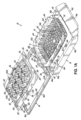
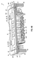
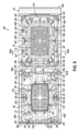
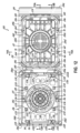
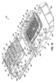
最初に図1、図1A、および図2を参照すると、本発明の例示的な実施形態により製作されたアセンブリ10が開位置にあるように図示されている。アセンブリ10は、周辺部分16を含む、フレーム14内に収められ、フレーム14に分離可能に結合されている、組織試料カセット12を備える。蓋18は、周辺部分16に分離可能に結合される。カセット12は、矩形構成を有するように示されているが、カセット12は、代替的構成を有し得ることは理解されるであろう。たとえば、カセットは、円形構成を有し得る。周辺部分16は、囲(周辺)側壁16a、16b、16c、16dの間に画成された内部11を全体として備え、蓋18は、内部に嵌合するようにサイズを決められ、構成され、囲壁16a、16b、16c、16dの少なくとも1つに分離可能に結合される。フレーム14は、囲外壁14a、14b、14c、14dと底縁14eとの間に画成された内部を全体として備え、カセット12は、上記の組み込まれている特許権において、同じ目的のために、全体として説明されているように、少なくとも第1の位置と第2の位置との間の内部の中で移動するようにサイズを決められ、構成される。第1の位置は、図3Bおよび図3Cに示されており、第2の、「ステージングされた」位置は、図3Dに示されている。第2の位置において、カセット12の下側部分は、フレーム14がミクロトームチャック内に保持されている間にカセット12および包埋された組織試料44がミクロトームで薄切りされることを可能にするようにフレーム14の底縁14eの下に露出される。
1, 1A, and 2, an
組織カセット12とフレーム14との接続は、上記の組み込まれている特許権において説明されている方式のうちのいずれかなど、多くの異なる方式で達成され得る。代替的に、カセット12は、本明細書において以下で説明されているような他の新規性のある方式でフレーム14に結合され得る。図1の例示的な実施形態において、カセット12は、囲壁14a、14b、14c、14dをカセット12に結合するフレームカセットコネクタ64を通してフレーム14に最初に分離可能に結合される。
The connection between the
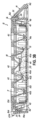
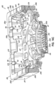
図4A~図4Cおよび図5Dを参照すると、各フレームカセットコネクタ64は、フレーム14と一体形成され、カセット12の側壁12a上など、カセット12と一体形成されたフランジ68などの、保持構造(たとえば、第2の保持構造)を通って少なくとも途中まで延在している、ピン66などの、保持構造(たとえば、第1の保持構造)を備える。各ピン66は、タブ70からほぼ上方に延在し、タブ70は外壁14a、14b、14c、14dのうちの1つからほぼ横方向内向きに延在する。ピン66は、タブ70上に配設された基部72と、フランジ68の対向面上の先端部74と、基部72からフランジ68を通って先端部74まで延在するシャフト76とを備える。先端部74は、シャフト幅80よりも大きい先端幅78を有していてもよい。全体として、先端部74およびタブ70はシャフト76よりも広く、フランジ68は先端部とタブとの間の陥凹部または下を切り取られた領域内に延在しているので、フランジは先端部とタブとによってピン66上に保持される。したがって、以下でより詳細に説明されているように、ステージング操作時にフレームカセットコネクタ64が分離(たとえば、破断)されるまで、フランジ68はピン66に固定されている。ピン66は、ほぼ円形の断面を有する直円柱または円錐台として形成され得る。この例示的な実施形態において、第1の保持構造はピン66であるが、他の実施形態では、第1の保持構造は、対応する第2の保持構造(たとえば、カセット12と一体形成されたフランジ68)を通って少なくとも途中まで延在して2つまたはそれ以上のコンポーネントを取り付けるか、または結合するように構成されている任意の形状または構造などの、他の形態を取り得ることは理解されるであろう。そのような第1の保持構造は、たとえば、また限定することなく、ペグ、バー、シャフト、ステム、スティックなどを含んでもよく、ほぼ円形、ほぼ卵形、またはほぼ多角形(たとえば、ほぼ正方形、五角形、六角形など)などの、任意の断面形状を有してもよい。それに加えて、第1の保持構造は、ほぼ真っ直ぐであるか、または1つまたは複数の湾曲部、曲がり、または角を含んでもよい。
4A-4C and 5D, each frame-
図4B(第1の位置)および図4C(第2の位置)を参照すると、この例示的な実施形態のフレームカセットコネクタ64は、壊れやすく、カセット12が第1の位置から第2の位置へ移動されると破断するように構成される。例示的な実施形態において、ピン66は、この移動の間に、フランジ68を引き裂いて出て、フランジ68を破断する。ピン66およびフランジ68に対する異なる相対的サイズまたは材料選択を有する他の実施形態では、ピン66またはタブ70は、ピン66がフランジ68を引き裂いて出る前に破断され得る。他の実施形態では、フレームカセットコネクタおよび蓋フレームコネクタ(後述)などの様々なコネクタは、破断せずに分離するように構成されてもよい。たとえば、いくつかのコネクタは、ピン、タブ、またはフランジを破断することなくピンがフランジから取り外されることを可能にする十分な弾性変形に対応できるように構成され得る。例示的な実施形態を再び参照すると、図4Bおよび図4Cのタブ70の配向を比較することによって分かるように、各タブ70は、第1の位置から第2の位置への移動時に、タブ70が下方に枢動し、フレームカセットコネクタ64の予測可能で一貫した分離(たとえば、破断)(たとえば、ピン66がフランジ68を引き裂いて出ること)を促し得るようにそのそれぞれの外壁14a、14b、14c、14dに枢動可能に結合され得る。
4B (first position) and 4C (second position), the frame-
蓋18とフレーム14の周辺部分16との接続は、上記の組み込まれている特許権において説明されている方式のうちのいずれかなど、多くの異なる方式で達成され得る。代替的に、蓋18は、本明細書において以下で説明されているような他の新規性のある方式でフレーム14の周辺部分16に結合され得る。図1の例示的な実施形態において、蓋18は、囲壁16a、16b、16c、16dを蓋18に結合する蓋フレームコネクタ36を通してフレーム14の周辺部分16に最初に分離可能に結合される。
The connection between the
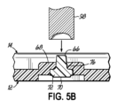
蓋フレームコネクタ36は、上で説明されているフレームカセットコネクタ64と構造および動作に関してほぼ類似しているものとしてよい。図4Cおよび図5Eを参照すると、各蓋フレームコネクタ36は、フレーム14の周辺部分16と一体形成され、蓋18と一体形成されたフランジ84などの、保持構造(たとえば、第2の保持構造)を通って少なくとも途中まで延在している、ピン82などの、保持構造(たとえば、第1の保持構造)を備える。各ピン82は、タブ86からほぼ下方に延在し、タブ86は囲壁16a、16b、16c、16dのうちの1つからほぼ横方向内向きに延在する。ピン82は、タブ86上に配設された基部88(図5E)と、フランジ84の対向面上の先端部90と、基部88からフランジ84を通って先端部90まで延在するシャフト92とを備える。先端部90は、シャフト幅96よりも大きい先端幅94を有していてもよい。ピン82は、ほぼ円形の断面を有する直円柱または円錐台として形成され得る。この例示的な実施形態において、第1の保持構造はピン82であるが、他の実施形態では、第1の保持構造は、対応する第2の保持構造(たとえば、カセット18と一体形成されたフランジ84)を通って少なくとも途中まで延在して2つまたはそれ以上のコンポーネントを取り付けるか、または結合するように構成されている任意の形状または構造などの、他の形態を取り得ることは理解されるであろう。そのような第1の保持構造は、たとえば、また限定することなく、ペグ、バー、シャフト、ステム、スティックなどを含んでもよく、ほぼ円形、ほぼ卵形、またはほぼ多角形(たとえば、ほぼ正方形、五角形、六角形など)などの、任意の断面形状を有してもよい。それに加えて、第1の保持構造は、ほぼ真っ直ぐであるか、または1つまたは複数の湾曲部、曲がり、または角を含んでもよい。
The
図4B(第1の位置)および図4C(第2の位置)を参照すると、この例示的な実施形態の蓋フレームコネクタ36は、壊れやすく、蓋18が第1の位置から第2の位置へ移動されると破断するように構成される。例示的な実施形態において、ピン82は、この移動の間に、フランジ84を引き裂いて出て、フランジ84を破断する。ピン82およびフランジ84に対する異なる相対的サイズまたは材料選択を有する他の実施形態では、ピン82またはタブ86は、ピン82がフランジ84を引き裂いて出る前に破断され得る。図4Bおよび図4Cのタブ86の配向を比較することによって分かるように、各タブ86は、第1の位置から第2の位置への移動時に、タブ86が下方に枢動し、蓋フレームコネクタ36の予測可能で一貫した分離(たとえば、破断)(たとえば、ピン82がフランジ84を引き裂いて出ること)を促し得るようにそのそれぞれの囲壁16a、16b、16c、16dに枢動可能に結合され得る。
4B (first position) and 4C (second position), the
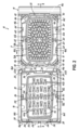
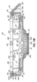
次に図2、図3A、および図3Bを参照すると、フレーム14と周辺部分16との間の接続部は、より詳しく説明されている。周辺部分16は、任意選択で壊れやすい、ヒンジ22a、22bの対によってフレーム14の壁14aに結合される。周辺部分16は、フランジ30、32などのコネクタを含み得る、フレーム閉鎖要素を伴うラッチ24、26などのコネクタを含み得る、周辺部分閉鎖要素の係合を通じて閉位置(図3B)にスナップ式に嵌合する。フックの形態を取り得る、ラッチ24は、周辺部分16の外壁16a上に位置決めされ、閉位置にあるフレーム14の壁14aのフランジ30と係合する。ラッチ26は、周辺部分16の壁16c上に位置決めされ、閉位置にあるフレーム14の壁14cのフランジ32と係合する(たとえば、スナップ式に嵌合する)。
2, 3A, and 3B, the connection between the
次に図1、図3A、および図3Bを参照すると、蓋18とカセット12との間の接続部は、より詳しく説明されている。蓋18は、ラッチ60などの、コネクタを含み得る、カセット閉鎖要素を伴う、フランジ58などの、コネクタを含み得る、蓋閉鎖要素の係合を通じて閉位置(図3B)にスナップ式に嵌合する。この実施形態では、蓋18は、閉位置にあるラッチ60の2つの対向する対とスナップ式に嵌合するように配置構成されている対向するフランジ58の対を備える。閉位置では、蓋18のフランジ58がカセット12のラッチ60と嵌合している状態で、蓋18およびカセット12は連結され、第1の位置(図3C)と第2の位置またはステージングされた位置(図3D)との間で単一のユニットとして移動する。
1, 3A, and 3B, the connection between the
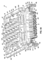
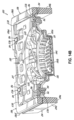
カセット12および蓋18は、図3Cおよび図3Dに最もよく示されているように、少なくとも第1の位置と第2の位置との間のフレーム14の内部内で移動するようにサイズを決められ、構成される。図2、図4B、および図4Cを参照すると、蓋18は、その4つの角の各々に蓋保持フランジ38を備えている。保持フランジ38は、フレーム14のカセット位置決め要素40と係合するように構成され、これらはフレーム14の四隅の内側隅の一部として形成される。例示的な実施形態において、各保持フランジ38は、それぞれのカセット位置決め要素40と係合する。カセット位置決め要素40は、保持フランジ38がカセット位置決め要素40のそばを(たとえば、下方に)通り過ぎるときに保持フランジ38がカセット位置決め要素40を変形させ、最終的に、たとえば、図4Cに示されているようにカセット位置決め要素40の下に「スナップ式」に嵌合するように可撓性を有し中空である。
The
図2、および図4A~図4Cに示されているように、フレーム14の各隅は、それぞれのカセット位置決め要素40の下に配置され、下方に離間する対角ストッパー46を含む。カセット12が第2の位置に到達すると、ストッパー46は、蓋18の保持フランジ38のさらなる下方への移動を妨げる。したがって、第2の位置では、蓋18の保持フランジ38は、カセット位置決め要素40(頂部)とストッパー46(底部)との間に垂直に固定される。蓋18とカセット12は、フランジ58とラッチ60によって連結されるので、これはカセット12および蓋18を第2の位置に保持し、上記の組み込まれている特許権において説明されているように、包埋およびその後のミクロトーム薄切をすぐに行えるようになっている。
2 and 4A-4C, each corner of the
図3Aに示されているように、1つまたは複数の組織試料44が、少なくとも1つの側壁12aによって囲まれ、底壁12bを含む陥凹部または内部領域11を画成するカセット12内に載置され得る。ほぼ矩形の陥凹部11が図示されているが(図2を参照)、任意の多角形(たとえば、正方形)または任意の丸い形状(たとえば、卵形もしくは円形)または組織試料44に対するトラフもしくはアラインメント特徴を有する形状などの、任意の他の形状が代わりに使用され得ることは理解されるであろう。
As shown in FIG. 3A, one or
この例示的な実施形態は、蓋18の下側に担持された弾力性のある構造も含む。弾力性のある構造は、弾力性のある指42の遠位端42aとカセット12内の1つまたは複数の組織試料44との間の可撓性係合を可能にすることを目的として湾曲した弾力性のある指42の形態を取る。弾力性のある指42は、処理時に組織試料44上に人為的痕跡を形成することなく望ましい配向および位置に組織44を保持する柔軟構造物を形成する。図4Aを参照すると、この実施形態では、弾力性のある指の遠位端42aは、蓋18が閉位置にあるときにほぼ下方に延在し得る、歯42bを備える。歯42bは、組織試料44の望ましくない移動に対する追加の安全をもたらし得る。
This exemplary embodiment also includes a resilient structure carried on the underside of the
異なる弾力性のある指42の材料または構成は、たとえば、処理され分析されるべき組織のタイプに基づき選択され得ることは理解されるであろう。たとえば、小さい粘膜組織試料は、弾力性のある指42のいくつかの配置構成を使用してうまく保持され、処理され得るが、脂肪組織などの他のタイプの組織には別の弾力性のある指42の材料または構成が使用されるとよりよい場合がある。別の例として、より大きい組織試料は、大きい表面領域上で適切に働く保持構造物を必要とし得る。それに加えて、弾力性のある指42は、組織固有の向きまたは整列保持特徴部を有し、非常に特異的な組織試料の配向を円滑にし得る。全体として、弾力性のある指は、均一もしくは不均一な配置構成または配向で蓋上に配設され得るか、形成され得るか(たとえば、形状、厚さ、もしくは長さ)、または様々なタイプ、サイズ、または厚さの組織試料を受け入れて保持することを円滑にするように望み通りに他の方法で修正され得る(たとえば、上記の組み込まれている特許権において開示されている構成に類似する)。
It will be appreciated that different
弾力性のある指42は、組織を固定し、処理し、染色するために使用される溶媒および化学薬品、ならび組織が弾力性のある指42によって保持されている間に組織を包埋するために使用される包埋材料の浸潤を可能にする。弾力性のある指42は、可撓性を有し、処理および包埋時に組織と係合し、組織を適所に保持するように構成される。さらに、弾力性のある指42は、カセットの陥凹部または内部領域がその後硬化する液化包埋材料を充填された後にミクロトームでうまく薄切りすることができる。弾力性のある指42は、たとえば、薄切可能プラスチックなどの、蓋18と同じ材料から形成されてよい。
The
次に図3Bおよび図3Cを参照すると、アセンブリ10は、周辺部分16が閉位置にあり、カセット12および蓋18が第1の位置にあるように図示されている。組織44がカセット12の内部または陥凹部11内に装填された後、周辺部分16が閉位置まで回転され得る。周辺部分16は、壊れやすいものであってもよい、ヒンジ22a、22bの周りに回転し、開位置から閉位置に移動する。ヒンジ22a、22bは、壊れやすく、そのような枢動はヒンジ22a、22bを切断し得る。周辺部分16は、ラッチ24、26がフレーム14のフランジ30、32と係合するまで回転し、周辺部分16をフレーム14にしっかり係止する。周辺部分16が閉位置にある場合に、弾力性のある指42は、組織試料44をカセット12の底壁12bの方へ付勢する。
3B and 3C, the
図3Bおよび図3Cにさらに示されているように、蓋18が閉じられたときに、弾力性のある指42は、組織試料44を圧迫し、組織試料44の周りで三次元的に変形し、組織試料44の周りに三次元空間を形成し、組織処理および包埋処置を行っているときに組織試料44を本質的に固定する。これは、また、カセット12の底壁12bに平坦に押し付けられ、それにより、底壁12bから蓋18に向かって徐々に、ミクロトーム薄片が作られるときに、組織試料44の完全な連続切片が形成されることを確実にする。試料44のすべてが薄く切断された後、次の薄片は、弾力性のある構造物42と包埋パラフィン蝋50のみを含むことになる。
3B and 3C, when the
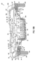
次に図3Dおよび図4Cを参照すると、カセット12および蓋18が第2の位置にあるアセンブリ10が図示されている。蓋18を下方に押すことは、蓋フレームコネクタ36およびフレームカセットコネクタ64が(上で説明されているように)分離することを引き起こし、蓋18およびカセット12を第1の位置(図3C)から第2の位置(図3D)に向かって移動することを可能にする。蓋18に対する継続的な下方の圧力は、蓋18がフレーム14の内部でさらに下方に摺動することを引き起こす。この下方への移動の間、蓋18の各隅(たとえば、保持フランジ38)は、フレーム14の内側隅上のそれぞれのカセット位置決め要素40と係合する。保持フランジ38は、カセット位置決め要素40のそばを通ったときにカセット位置決め要素40を変形させ、最終的に図4Cに示されているようにカセット位置決め要素40の下に「スナップ式に」嵌合し、これは蓋18およびカセット12の上方への移動を妨げる。カセット12が第2の位置に到達すると、ストッパー46は、蓋18のフランジ38のさらなる下方への移動を妨げる。これは、包埋およびその後のミクロトーム薄切プロセスにおいてカセット12および蓋18を第2の位置に保持する。
3D and 4C, the
第2の位置において、組織試料44、カセット12の一部、および弾力性のある指42の一部分は、ミクロトームで薄切りされるようにステージングされる。カセット位置決め要素40およびストッパー46は、蓋18の移動を第2の位置で制限するので、カセット位置決め要素40およびストッパー46は、カセット12が、カセット12の構成から独立して所定の深さまでステージングされることを確実にする。所定の深さまでステージングすることで、カセット12の底壁12bが所定の垂直間隔などで包埋モールド52に関して望み通りに位置決めされることを確実にする(図3D参照)。これは、以下で説明されているプロセスにおける自動化ミクロトームの使用を円滑にするが、それは、底壁12bに当たって保持されている組織試料44に到達する前に取り除かれなければならない包埋材料の厚さが、すべてのカセットについて実質的に同じになるからである。
In the second position, the
これらのようなアセンブリを利用して毎年数百万もの処置が遂行されているので、本発明の実施形態は、高い生産量に合わせて設計され、その結果、自動化された組織病理学プロセスでの使用に向けられる。そのような一プロセスは、自動化された包埋である。例示的な自動化包埋機は、カセットをフレームに通して、図3Cおよび図3Dに示されているような包埋モールド52内に押し込むモーター駆動ステージングデバイス48を使用する。ステージングデバイス48は、蓋18およびカセット12をフレーム14に押し通すバネ仕掛けの円筒形指または足を組み込むものとしてよい。
Because millions of procedures are performed annually utilizing assemblies such as these, embodiments of the present invention are designed for high throughput and, as a result, are directed to use in automated histopathology processes. One such process is automated embedding. An exemplary automated embedding machine uses a
使用時に、1つまたは複数の組織試料44は、図3Aに示されているように、内部空間または陥凹部内に、また特に、カセット12の底壁12bに載置される。組織試料44は、各組織試料44について病理学者によって望まれている必要な切片平面に従ってカセット12内でサイズを決められ向き付けられる。次いで、周辺部分16は閉じられ、弾力性のある指42が、図3Bに示されているような望ましい配向で底壁12bに圧接し、底壁12bに対して組織試料44を捕捉するように適所にスナップ式に嵌合される。弾力性のある指42は、三次元的に変形して組織試料44の様々なサイズおよび形状に対応できるものとしてよい。組織試料44に及ぼす弾力性のある指42の力は、組織試料44を固定し、底壁12bに対してそれを捕捉するのには十分であるが、組織試料44内にアーチファクトを誘発するのには十分でないものであるべきである。この時点で、捕捉された組織試料44を伴うアセンブリ10は、真空、熱、および化学薬品を使用して組織内の間質液を取り除き、それらの流体を溶融パラフィンなどの硬化性材料で置き換える従来の組織処理作業に通されるものとしてよい。上で述べたように、これらの処理ステップにおいて、弾力性のある指42および底壁12bは、流体が組織試料44に到達し、組織試料44内に完全に浸潤することを可能にする。
In use, one or
弾力性のある指42を含む、カセット12、フレーム14、および蓋18の例示されている構成は、組織試料44がカセットの底壁12bに当たって適切に固定されることを確実にするために使用者が蓋とカセットとの間の制限された数の特定の係合距離から選択しなければならない複雑な蓋調整手順を必要とするアセンブリに勝る改善となっている。特定の係合距離は、蓋を係合し、保持したカセットバスケットの内部にあるプリセットタブによって決定された。例示的な実施形態、特に弾力性のある指42(または本明細書において開示されている他の類似の組織付勢構造)を利用することによって、蓋に対する複雑な調整手順がなくなる。したがって、いくつかの例示的な実施形態では、蓋の閉鎖および組織試料の適切な固定化(過度の変形なし)は、組織試料の厚さにかかわらず、蓋が閉じられ、弾力性のある指42(または他の類似の付勢構造)が組織試料44を付勢してカセット12の底壁12bに押し付ける単純な「ワンスナップ」手順によって達成され得る。類似の目的を達成するために他の構成および設計が使用され得ることは理解されるであろう。
The illustrated configuration of the
組織処理が完了した後、次いで、カセット12およびフレーム14は、好適なモールド52内に載置され、パラフィン内に包埋される。カセット12および/またはフレーム14は、機械が使用されるカセット12のタイプおよびサイズを決定し、包埋のためにカセット12をどのモールドに載置するかに関する適切な決定を下すことを可能にする機械で読み取れる印を備え得る。カセット12の露出されている部分を含むアセンブリ10は全体が、パラフィン蝋の硬化したブロック内に包埋される。モールド52は、カセット12の底部12bの輪郭をほぼなぞるが、カセット12を囲むモールドの部分は、好ましくは、丸形とは反対に正方形である。これは、リボン状薄片のその後の作製を補助する。したがって、処置のこの部分は、上記の組み込まれている特許権において開示されているものに類似しているものとしてよい。次いで、そこで説明されているように、フレーム14は、包埋アセンブリ10をミクロトーム内に装着するための固定具として使用される。必要な数の薄片は、十分な切片または薄片が取られ、適切に顕微鏡用スライド上に装着され、染色され、カバースリップされるまで露出されている下側から取り去られる。
After tissue processing is complete, the
組織試料44をアセンブリ10に装填する別の方法(図示せず)が可能である。最初に、周辺部分16がフレーム14から外されるが、これは取っておく。組織試料44が弾力性のある指42上に載置され、次いで、フレーム14が蓋18の上に設置される。フレーム14が周辺部分16の上に設置されるときに、周辺部分16のラッチ24、26は、フレーム14の、それぞれ、指30、32と係合する。この方式で、周辺部分16は、フレーム14に固定される。次いで、アセンブリ10が通常の直立位置に位置決めされ得るが、弾力性のある蓋18は、フレーム14に結合されたままであり、弾力性のある指42は、組織試料44をカセット12の底壁12bに固定する。
An alternative method (not shown) of loading the
全体として、カセット12(およびいくつかの実施形態では、蓋18)は、比較的剛性の低い材料から形成されてもよく、フレーム14(およびいくつかの実施形態では、蓋18)は、比較的剛性の高い材料から形成されてもよい。カセット12は、上記の組み込まれている特許権に従って、ペルフルオロアルコキシエチレン(PFA)、またはポリエチレン(PE)系もしくはポリエチレン(PE)含有材料などの、薄切可能プラスチックから形成され得る。カセット12を形成する材料は、組織分析時に注意を逸らされないように少なくとも半透明であってよい。周辺部分16を含む、フレーム14は、アセタールなどの、剛性が高く安価なプラスチックから形成され得る。アセタールは、大量に、または数個取り射出成形モールドで成形するのがかなり容易である。図1Aを見ると分かるように、カセット12は、フレーム14とは別に成形され、次いでフレーム14内に挿入され得る。同様に、蓋18は、周辺部分16とは別に成形され、次いで周辺部分16内に挿入され得る。さらに、カセット12およびフレーム14が著しく異なる溶融温度を有する材料から作られるときに、図6A~図6Dに関連して以下で説明されているツーショット技術を使用するなどして、挿入成形または共成形され得る。いくつかの例示的な実施形態において、カセット12、蓋18、およびフレーム14は、顧客が受け取る前に一体品に組み合わされてよく、アセンブリは、組織をすぐに装填できる一体品として届く。これは、組織を装填する前にコンポーネントを使用者側で組み立てる必要があった以前のアセンブリよりも有利である。
In general, the cassette 12 (and in some embodiments, the lid 18) may be formed from a relatively less rigid material, and the frame 14 (and in some embodiments, the lid 18) may be formed from a relatively more rigid material. The
図5Eは、コネクタ64と構造的に類似しているが、ほぼ逆の構成であるピンコネクタ36を示している。
Figure 5E shows
図5A~図5Dは、特にフレームカセットコネクタ64に関連する、例示的な組立プロセスを例示している。図5Aは、フレーム14と、タブ70およびピン66を含む、それと一体形成されるコンポーネントを示している。注目すべきは、ピン66はまだその広い先端部74(図5Cおよび図5D)を含んでいないことである。ピン66は、ほぼ円錐台であってよく、これは、フレーム14および関連するコンポーネントを形成するために使用されるモールドの離型を円滑にし得る。図5Bは、ピンのシャフト76がフランジ68を通って延在するようにピン66に関して位置決めされたフランジ68を含む、カセットおよびそれと一体的に形成されたコンポーネントを示している。これは、別々に成形されたフレーム14およびカセット12を組み立てることによって達成され得るか、またはフレーム14およびカセット12を適所に順次成形することによっても達成され得る。図5Bは、また、ピン66に接近する工具98を示している。図5Cは、そのシャフト76の遠位部分が工具98の操作によって比較的広い先端部74内に形成されるピン66を示している。先端部74を形成するためのピン66のこの変形は、カセット12のフランジ68をフレーム14のピン66に固定する。いくつかの例示的なプロセスにおいて、先端部74は、シャフト76の遠位部分が工具によって容易に塑性変形され得るようにピン66が室温より高いがその溶融温度より低い温度であるときに工具98によって形成され得る。図5Dは、すでに説明されているように完成したフレームカセットコネクタ64を示している。ほぼ類似している、対応するプロセスが、蓋フレームコネクタ36を組み立てるために使用され得る。
5A-5D illustrate an exemplary assembly process, particularly as it relates to the frame-
図6A~図6D、図7A~図7C、および図7D~図7Fは、ピン/フランジコネクタおよび関連する組立方法を含む代替的な例示的保持構造を示している。図5A~図5Eに関して上で説明されている例、または図6A~図6D、図7A~図7C、および図7D~図7Fに関して以下で説明されている代替的例のいずれかは、本開示による様々な実施形態に関連して利用され得る。図6A~図6Dは、ツーショット、共成形プロセスのステップを示す代替的なピン/フランジコネクタ600の断面図である。図6Aにおいて、ピン602は、射出成形などによる第1のコンポーネント604と一体形成される。この操作は、第1の成形操作または第1のショットと称され得る。図1に例示されているアセンブリ10の文脈では、第1のコンポーネント604は、フレーム14であってもよい。図6Bにおいて、モールド/工具612が、第1のコンポーネント604に接近して示されている。図6Cを参照すると、モールド/工具612は、第1のコンポーネント604と係合してピン602を変形させ、より幅広のトラス頭形状の先端部614を形成する。いくつかの例示的なプロセスにおいて、先端部614は、ピンの遠位部分がモールド/工具によって容易に塑性変形され得るようにピン602が室温より高いがその溶融温度より低い温度であるときにモールド/工具612によって形成され得る。それに加えて、モールド/工具612は、第1のコンポーネント604と係合して、第2の材料を成形するための1つまたは複数のキャビティ610を少なくとも部分的に画成する。図6Dに示されているように、キャビティ610は、第2の成形操作または第2のショットで充填され、ピン602の周りに配設された、第2のコンポーネント608と一体形成された、フランジ606を形成する。全体として、フランジ606は、先端の下の陥凹部または下切り取り部内に、ピン602を取り囲んで、延在するので、フランジは、コネクタ600がステージング操作で分離(たとえば、破断)されるまで、ピンに固定されている。図1に例示されているアセンブリ10の文脈では、第2のコンポーネント608は、フレーム12であってもよい。そのようなツーショット成形プロセスは、たとえば、より少ない取り扱いおよび組み立てステップを伴い得るので、いくつかの他の潜在的な組立または成形プロセスと比較して有利であり得る。例示的なツーショットプロセスでは、第1のコンポーネント604は、モールド内で形成され得る。モールドから第1のコンポーネント604を取り外すことなく、モールドは、モールド/工具612を受け入れるように再構成され得る(たとえば、90度回転)。次いで、第2のコンポーネント608が成形され得る。最後に、第1のコンポーネント604および第2のコンポーネント608は、現在接続されているが、取り外され得る。したがって、この例示的なツーショットプロセスは、第1のモールドから第2のモールドへの第1のコンポーネントの移送、または別々に成形されたコンポーネントの組立を必要とし得ない。
6A-6D, 7A-7C, and 7D-7F show alternative exemplary retention structures including pin/flange connectors and associated assembly methods. Any of the examples described above with respect to FIGS. 5A-5E or alternative examples described below with respect to FIGS. 6A-6D, 7A-7C, and 7D-7F may be utilized in connection with various embodiments according to the present disclosure. FIGS. 6A-6D are cross-sectional views of an alternative pin/
他の例示的なプロセスでは、第1のコンポーネント604が形成され、次に第2のモールド内に載置され得る。次いで、第2のコンポーネント608は、共成形または挿入成形プロセスなどにより、第1のコンポーネント604上に直接的に、射出成形などによって、形成され得る。全体として、第1のコンポーネント604は、離型を円滑にするために、任意のキャビティが深さの増大とともに全体として狭くなるような形状を取り得る。同様に、ピン602は、離型を円滑にするために狭い方の端部が外を向いている、ほぼ円錐台であってもよい。
In another exemplary process, the
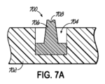
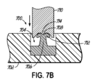
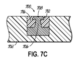
図7A~図7Cは、組立プロセスのステップを示す代替的なピン/フランジコネクタ700の断面図である。図7Aにおいて、第1のコンポーネント702は、ピン706が設置され固定される陥凹部704を備える。たとえば、ピン706は、接着剤を使用して陥凹部704内に固定され得る。第1のコンポーネント702は、第1の材料で形成されてもよく、ピン706は、第2の材料で形成されてもよい。ピン706は、ほぼ円錐台であってよく、その遠位端に陥凹部708を備える。図7Bにおいて、工具710がピン706上に先端部712を形成している。工具710は、ピン706の陥凹部708と係合するように配置構成されている中央突出部714を備える。図7Cにおいて、第2のコンポーネント716(たとえば、フランジを含む)が、射出成形などによって、ピン706の周りの陥凹部704に成形されている。第2のコンポーネント716は、第3の材料から形成され得る。したがって、コネクタ700は、第1のコンポーネント702および第2のコンポーネント716を結合する。より具体的には、第2のコンポーネント716のフランジは、先端部712の下の陥凹部または下切り取り部内に、ピン706を取り囲んで、延在するので、第2のコンポーネントは、コネクタ700がステージング操作で分離(たとえば、破断)されるまで、第1のコンポーネント702に固定されている。
7A-7C are cross-sectional views of an alternative pin/
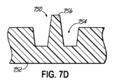
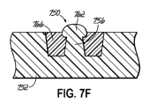
図7D~図7Fは、組立プロセスのステップを示す代替的なピン/フランジコネクタ750の断面図である。ピンコネクタ750は、ピン756が第1のコンポーネント752と一体形成され得ることを除き、ピンコネクタ700にほぼ類似しているものとしてよい。図7Dにおいて、第1のコンポーネント752は、ピン756が一体形成される陥凹部754を備える。第1のコンポーネント752およびピン756は、第1の材料から形成されてもよい。ピン756は、ほぼ円錐台であってよい。図7Bにおいて、工具760がピン756上に先端部756を形成している。代替的に、適切な幾何学的形状を有するいくつかの例示的な実施形態において、先端部762は、工具760および別個の先端部形成ステップが省かれ得るように第1のコンポーネント752の最初の成形中に成形され得る。図7Fにおいて、第2のコンポーネント766(たとえば、フランジを含む)が、第2のモールドにおける射出成形などによって、ピン756の周りの陥凹部754内に成形されている。第2のコンポーネント766は、第2の材料から形成され得る。したがって、コネクタ750は、第1のコンポーネント752および第2のコンポーネント766を結合する。より具体的には、第2のコンポーネント766のフランジは、先端部762の下の陥凹部または下切り取り部内に、ピン756を取り囲んで、延在するので、第2のコンポーネントは、コネクタ750がステージング操作で分離(たとえば、破断)されるまで、第1のコンポーネント752に固定されている。
7D-7F are cross-sectional views of an alternative pin/
いくつかの例示的なフレームカセットコネクタ、蓋フレームコネクタ、および他のコンポーネントを形成し組み立てるためのいくつかの例示的なプロセスが本明細書において説明されているが、そのようなコネクタを含む様々なデバイスおよびそれらのデバイスを使用する方法は、デバイスが上で説明されているプロセス、従来のプロセス、または将来開発されるプロセス、またはそれらの任意の組合せを使用して生産されるかどうかにかかわらず、本開示の範囲内にあり得ることは理解されるべきである。 Although several exemplary processes for forming and assembling several exemplary frame-cassette connectors, lid-frame connectors, and other components are described herein, it should be understood that various devices including such connectors and methods of using those devices may be within the scope of the present disclosure, whether the devices are produced using the processes described above, conventional processes, or future developed processes, or any combination thereof.
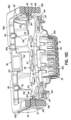
図8、図9、および図10A~図10Cは、図1、図1A、図2、図3A~図3D、および図4A~図4Cに関して図示され説明されているアセンブリ10にほぼ類似しているアセンブリ100の別の例示的な実施形態を示している。類似の参照数字は、上で図示され、説明されている類似の構造を指す。特に示されない限り、アセンブリ10に関する対応するコンポーネントの構造および機能または方法論の説明は、全体としてアセンブリ100に適用される。したがって、すでに説明されている構造物および機能または方法の説明の繰り返しは不要である。この実施形態では、アセンブリ10の弾力性のある指42は、ほぼ矩形のプラテン142および付勢部材120によって置き換えられている。さらに、アセンブリ100は、蓋閉鎖要素およびカセット閉鎖要素の異なる配置構成を含む。
8, 9, and 10A-10C show another exemplary embodiment of an
アセンブリ100は、少なくとも1つの側壁112aによって囲まれ、底壁112bを含む陥凹部または内部領域111を含む組織試料カセット112を備える。カセット112は、周辺部分116を含む、フレーム114内に収められ、フレーム114に分離可能に結合されている。蓋118は、周辺部分116に分離可能に結合される。周辺部分116は、全体として、囲(周辺)壁116a、116b、116c、116dの間に画成された内部を含み、蓋118は、内部に嵌合するようにサイズを決められ、構成され、囲壁116a、116b、116c、116dの少なくとも1つに分離可能に結合される。フレーム114は、全体として、囲外壁114a、114b、114c、114dと底縁114eとの間に画成された内部を含み、カセット112は、アセンブリ10に関連して、同じ目的に関して上で全体として説明されているように、少なくとも第1の位置と第2の位置との間で内部内を移動するようにサイズを決められ、構成される。第1の位置は、図10Bに示されており、第2の、「ステージングされた」位置は、図10Cに示されており、そこでは、カセット112の下側部分は、フレーム114がミクロトームチャック内に保持されている間にカセット112および包埋組織試料がミクロトーム内で薄切りされることを可能にするようにフレーム114の底縁114eの下に露出される。
The
組織カセット112とフレーム114との接続は、上で説明されている方式のうちのいずれかなど、多くの異なる方式で達成され得る。図8の例示的な実施形態において、カセット112は、囲壁114a、114b、114c、114dをカセット112に結合するフレームカセットコネクタ164を通してフレーム114に最初に分離可能に結合される。フレームカセットコネクタ164は、アセンブリ10に関連して上で説明されているフレームカセットコネクタ64と構造および動作が類似している。この例示的な実施形態において、フレームカセットコネクタ164は、壊れやすい。
The connection between the
蓋118とフレーム114の周辺部分116との接続は、上で説明されている方式のうちのいずれかなど、多くの異なる方式で達成され得る。図8の例示的な実施形態において、蓋118は、囲壁116a、116b、116c、116dを蓋118に結合する蓋フレームコネクタ136を通してフレーム114の周辺部分116に最初に分離可能に結合される。蓋フレームコネクタ136は、アセンブリ10に関連して上で説明されている蓋フレームコネクタ36と構造および動作が類似している。この例示的な実施形態において、蓋フレームコネクタ136は、壊れやすい。
The connection between the
次に図8および図9を参照すると、フレーム114と周辺部分116との間の接続部は、より詳しく図示されている。周辺部分116は、任意選択で壊れやすい、ヒンジ122a、122bの対によってフレーム114の壁114aに結合される。周辺部分116は、フランジ130、132などの、フレーム閉鎖要素を伴う、ラッチ124、126などの、周辺部分閉鎖要素の係合を通じて閉位置(図10B)にスナップ式に嵌合する。ラッチ124は、周辺部分116の外壁116a上に位置決めされ、閉位置にあるフレーム114の壁114aのフランジ130と係合する。ラッチ126は、周辺部分116の壁116c上に位置決めされ、閉位置にあるフレーム114の壁114cのフランジ132と係合する。
8 and 9, the connection between the
次に図8、図9、および図10Aを参照すると、蓋118とカセット112との間の接続部は、より詳しく図示されている。蓋118は、フランジ160などの、コネクタを含み得る、カセット閉鎖要素を伴う、ラッチ158などの、コネクタを含み得る、蓋閉鎖要素の係合を通じて閉位置(図10B)にスナップ式に嵌合する。この実施形態では、各ラッチ158は、それぞれの延在するアーム159上に配設される。アーム159は、蓋118が閉位置にあるとき、蓋118からほぼ下方に延在する。アーム159およびラッチ158の対応する対は、蓋118の各側面に配設され、各対のアーム159およびラッチ158はラッチ158が互いに向き合うように離間する対向配置構成で蓋上に配設される。カセット112の各フランジ160は、ほぼ横方向に配向され、アーム159の対応する対の両方のラッチ158に係合するように配置構成される。閉位置では、蓋118のラッチ158がカセット112のフランジ160と嵌合している状態で、蓋118およびカセット112は連結され、第1の位置(図10B)と第2の位置またはステージングされた位置(図10C)との間で単一のユニットとして移動する。全体として、蓋閉鎖要素は、蓋をカセットに固定し、様々な処理操作時など、蓋がカセット上に閉じられた後に蓋およびカセットが分離するのを妨げる役割を果たす。組織試料をカセットの底壁に対して付勢するように配置構成されている蓋装着コンポーネントを含むいくつかの例示的な実施形態では、蓋閉鎖要素は、蓋をカセットから分離する傾向があり得る対応する反力に耐えるように構成され得る。
8, 9, and 10A, the connection between the
カセット112および蓋118は、アセンブリ10に関して上で説明されている方式と類似の方式で図10Bおよび図10Cに最もよく示されているように、少なくとも第1の位置と第2の位置との間のフレーム114の内部内で移動するようにサイズを決められ、構成される。蓋118は、その4つの隅の各々において蓋保持フランジ138を備える。保持フランジ138は、フレーム114のカセット位置決め要素140と係合するように構成され、これらはフレーム114の四隅の内側隅の一部として形成される。例示的な実施形態において、各保持フランジ138は、それぞれのカセット位置決め要素140と係合する。カセット位置決め要素140は、保持フランジ138がカセット位置決め要素140のそばを(たとえば、下方に)通り過ぎるときに保持フランジ138がカセット位置決め要素140を変形させ、最終的に、たとえば、図10Cに示されているようにカセット位置決め要素140の下に「スナップ式」に嵌合するように可撓性を有し中空である。
The
図9および図10Bに示されているように、フレーム114の各隅は、それぞれのカセット位置決め要素140の下に配置され、下方に離間する対角ストッパー146を含む。カセット112が第2の位置に到達すると、ストッパー146は、蓋118の保持フランジ138のさらなる下方への移動を妨げる。したがって、第2の位置では、蓋118の保持フランジ138は、カセット位置決め要素140(頂部)とストッパー146(底部)との間に垂直に固定される。蓋118とカセット112は、ラッチ158およびフランジ160によって連結されるので、これはカセット112および蓋18を第2の位置に保持し、上で説明されているように、包埋およびその後のミクロトーム薄切をすぐに行えるようになっている。
9 and 10B, each corner of the
図8、図9、および図10A~図10Cを参照すると、上で説明されているアセンブリ10の弾力性のある指42の代わりに、この実施形態の蓋118は、カセット112のほぼ矩形の陥凹部111内に受け入れられるように構成されているプラテン142を備える弾力性のある構造を備える。プラテン142は、ほぼ矩形であり、複数の付勢部材120によって蓋118の周辺部分117に結合される。付勢部材120は、蓋118が閉構成にあるときに、カセット112の底壁112bに向かってプラテン142を付勢するように配置構成される。この実施形態では、付勢部材120は、プラテン142と蓋118の周辺部分117との間のほぼ垂直な配置構成で配設される。
8, 9, and 10A-10C, instead of the
全体として、付勢部材120は、プラテン142とカセット112の陥凹部111内の1つまたは複数の組織試料との間の可撓性係合を可能にするように弾性的変形可能である。プラテン142および付勢部材120は、処理時に組織試料上に人為的痕跡を形成することなく望ましい配向に組織を保持する柔軟構造物を形成する。ほぼ矩形の陥凹部111が図示されているが、任意の多角形(たとえば、正方形)または任意の丸い形状(たとえば、卵形もしくは円形)または組織試料に対するトラフもしくはアラインメント特徴を有する形状などの、任意の他の形状が代わりに使用され得ることは理解されるであろう。
Collectively, the biasing
プラテン142は、組織を固定し、処理し、染色するために使用される溶媒および化学薬品、ならび組織がプラテン142によって保持されている間に組織を包埋するために使用される包埋材料の浸潤を可能にする。プラテン142は、可撓性を有し、処理および包埋時に組織と係合し、組織を適所に保持するように構成される。さらに、プラテン142は、カセットの陥凹部111または内部領域がその後硬化する液化包埋材料を充填された後にミクロトームでうまく薄切りすることができる。プラテン142は、たとえば、薄切可能プラスチックなどの、蓋118と同じ材料から形成されてよい。
The
図10Aを参照すると、この実施形態では、プラテン142の組織接触側は、蓋118が閉位置にあるときにほぼ下方に延在し得る、歯142bを備える。歯142bは、組織試料の望ましくない移動に対する追加の安全をもたらし得る。
Referring to FIG. 10A, in this embodiment, the tissue-contacting side of the
全体として、アセンブリ100は、組織を装填され、開位置から閉位置へ移動され(壊れやすい蓋フレームコネクタ136およびフレームカセットコネクタ164を破断することを含む)、ステージングされ、さもなければ上で説明されているアセンブリ10に類似する方式で使用される。使用時に、1つまたは複数の組織試料は、内部空間または陥凹部111内に、また特に、カセット112の底壁112bに載置される。組織試料は、病理学者によって望まれている必要な切片平面に従ってカセット112内でサイズを決められ配向される。次いで、周辺部分116は閉じられ、プラテン142が、望ましい配向で底壁112bに圧接し、底壁112bに対して組織試料を捕捉するように適所にスナップ式に嵌合される。付勢部材120は、プラテン142が組織試料の様々なサイズおよび形状に対応できることを可能にするように変形する。組織試料に及ぼすプラテン142の力は、組織試料を固定するのには十分であるが、組織試料内にアーチファクトを誘発するのには十分でないものであるべきである。この時点で、捕捉された組織試料を伴うアセンブリ100は、真空、熱、および化学薬品を使用して組織内の間質液を取り除き、それらの流体を溶融パラフィンなどの硬化性材料で置き換える従来の組織処理作業に通されるものとしてよい。上で述べたように、これらの処理ステップにおいて、プラテン142および底壁112bは、流体が組織試料に到達し、組織試料内に完全に浸潤することを可能にする。それに加えて、プラテン142は、顕微鏡下でのその後の分析を妨げるおそれのある組織上のアーチファクトまたはマーキングを残すことなく底壁112bに対して組織試料を平坦に捕捉する。異なる付勢部材120およびプラテン142は、たとえば、処理され分析されるべき組織のタイプに基づき選択され得ることは理解されるであろう。たとえば、小さい粘膜組織試料は、いくつかの配置構成を使用してうまく保持され、処理され得るが、脂肪組織などの他のタイプの組織には別の材料または構成が使用されるとよりよい場合がある。たとえば、付勢部材の厚さ、形状、および個数は、組織試料に望ましい固定する力を印加するように選択され得る。
Generally, the
組織処理が完了した後、次いで、カセット112およびフレーム114は、好適なモールド内に載置され、パラフィン内に包埋される。カセット112および/またはフレーム114は、機械が使用されるカセット112のタイプおよびサイズを決定し、全体としてアセンブリ10を参照しつつ上で説明されている方式で包埋のためにカセット112をどのモールドに載置するかに関する適切な決定を下すことを可能にする機械で読み取れる印を備え得る。
After tissue processing is complete, the
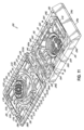
図11、図12、図13A、図13B、および図14A~図14Cは、図8、図9、および図10A~図10Cに関して図示され、説明されているアセンブリ100に類似するアセンブリ200の別の例示的実施形態さらにはアセンブリ10を示している。図11、図12、図13A、図13B、および図14A~図14Cの類似の参照番号は、上で図示され、説明されている類似の構造を指す。特に示されない限り、アセンブリ100およびアセンブリ10に関する対応するコンポーネントの構造および機能または方法論の説明は、全体としてアセンブリ200に適用される。したがって、すでに説明されている構造物および機能または方法が説明の繰り返しは不要である。この実施形態では、アセンブリ100のほぼ矩形のプラテン142は、ほぼ円形のプラテン242で置き換えられており、アセンブリ100のほぼ垂直の付勢部材120は、ほぼ螺旋状の付勢部材220で置き換えられている。さらに、アセンブリ200は、蓋閉鎖要素およびカセット閉鎖要素の異なる配置構成を含む。
11, 12, 13A, 13B, and 14A-14C show another exemplary embodiment of
アセンブリ200は、少なくとも1つの側壁212aによって囲まれ、底壁212bを含む陥凹部または内部領域211を含む組織試料カセット212を備える。カセット212は、周辺部分216を含む、フレーム214内に収められ、フレーム214に分離可能に結合されている。蓋218は、周辺部分216に分離可能に結合される。周辺部分216は、全体として、囲(周辺)壁216a、216b、216c、216dの間に画成された内部を含み、蓋218は、内部に嵌合するようにサイズを決められ、構成され、囲壁216a、216b、216c、216dの少なくとも1つに分離可能に結合される。フレーム214は、全体として、囲外壁214a、214b、214c、214dと底縁214eとの間に画成された内部を含み、カセット212は、アセンブリ100に関連して、同じ目的に関して上で全体として説明されているように、少なくとも第1の位置と第2の位置との間で内部内を移動するようにサイズを決められ、構成される。第1の位置は、図14Bに示されており、第2の、「ステージングされた」位置は、図14Cに示されており、そこでは、カセット212の下側部分は、フレーム214がミクロトームチャック内に保持されている間にカセット212および包埋組織試料がミクロトーム内で薄切りされることを可能にするようにフレーム214の底縁214eの下に露出される。
The
組織カセット212とフレーム214との接続は、上で説明されている方式のうちのいずれかなど、多くの異なる方式で達成され得る。図11の例示的な実施形態において、カセット212は、囲壁214a、214b、214c、214dをカセット212に結合するフレームカセットコネクタ264を通してフレーム214に最初に分離可能に結合される。フレームカセットコネクタ264は、アセンブリ100に関連して上で説明されているフレームカセットコネクタ164と構造および動作が類似している。この例示的な実施形態において、フレームカセットコネクタ264は、壊れやすい。
The connection between the
蓋218とフレーム214の周辺部分216との接続は、上で説明されている方式のうちのいずれかなど、多くの異なる方式で達成され得る。図11の例示的な実施形態において、蓋218は、囲壁216a、216b、216c、216dを蓋218に結合する蓋フレームコネクタ236を通してフレーム214の周辺部分216に最初に分離可能に結合される。蓋フレームコネクタ236は、アセンブリ100に関連して上で説明されている蓋フレームコネクタ136と構造および動作が類似している。この例示的な実施形態において、蓋フレームコネクタ236は、壊れやすい。
The connection between the
次に図11、図12、および図13Aを参照すると、フレーム214と周辺部分216との間の接続部は、より詳しく図示されている。周辺部分216は、任意選択で壊れやすい、ヒンジ222a、222bの対によってフレーム214の壁214aに結合される。周辺部分216は、フランジ230、232などの、フレーム閉鎖要素を伴う、ラッチ224、226などの、周辺部分閉鎖要素の係合を通じて閉位置(図14B)にスナップ式に嵌合する。ラッチ224は、周辺部分216の外壁216a上に位置決めされ、閉位置にあるフレーム214の壁214aのフランジ230と係合する。ラッチ226は、周辺部分216の壁216c上に位置決めされ、閉位置にあるフレーム214の壁214cのフランジ232と係合する。
11, 12, and 13A, the connection between the
次に図11、図12、および図14Aを参照すると、蓋218とカセット212との間の接続部は、より詳しく図示されている。蓋218は、フランジ260などの、コネクタを含み得る、カセット閉鎖要素を伴う、ラッチ258などの、コネクタを含み得る、蓋閉鎖要素の係合を通じて閉位置(図14B)にスナップ式に嵌合する。この実施形態では、4つのラッチ258の各々は、それぞれの延在するアーム259上に配設される。アーム259は、蓋218が閉位置にあるとき、蓋218からほぼ下方に延在する。アーム259は、プラテン242をほぼ囲む離間する配置構成に配設され、ラッチ258は、それぞれのアームからほぼ横方向外向きに面する。カセット212の4つのフランジ260の各々は、ほぼ横方向に配向され、1つのラッチ258と係合するように配置構成される。閉位置では、蓋218のラッチ258がカセット212のフランジ260と嵌合している状態で、蓋218およびカセット212は連結され、第1の位置(図14B)と第2の位置またはステージングされた位置(図14C)との間で単一のユニットとして移動する。
11, 12, and 14A, the connection between the
カセット212および蓋218は、アセンブリ100に関して上で説明されている方式と類似の方式で図14Bおよび図14Cに最もよく示されているように、少なくとも第1の位置と第2の位置との間のフレーム214の内部内で移動するようにサイズを決められ、構成される。蓋218は、その4つの隅の各々において蓋保持フランジ238を備える。保持フランジ238は、フレーム214のカセット位置決め要素240と係合するように構成され、これらはフレーム214の四隅の内側隅の一部として形成される。例示的な実施形態において、各保持フランジ238は、それぞれのカセット位置決め要素240と係合する。カセット位置決め要素240は、保持フランジ238がカセット位置決め要素240のそばを(たとえば、下方に)通り過ぎるときに保持フランジ238がカセット位置決め要素240を変形させ、最終的に、たとえば、図14Cに示されているようにカセット位置決め要素240の下に「スナップ式」に嵌合するように可撓性を有し中空である。
The
図14Aに示されているように、フレーム214の各隅は、それぞれのカセット位置決め要素240の下に配置され、下方に離間する対角ストッパー246を含む。カセット212が第2の位置に到達すると、ストッパー246は、蓋218の保持フランジ238のさらなる下方への移動を妨げる。したがって、第2の位置では、蓋218の保持フランジ238は、カセット位置決め要素240(頂部)とストッパー246(底部)との間に垂直に固定される。蓋218とカセット212は、ラッチ258とフランジ260によって連結されるので、これはカセット212および蓋218を第2の位置に保持し、上記の組み込まれている特許権において説明されているように、包埋およびその後のミクロトーム薄切をすぐに行えるようになっている。
14A, each corner of the
図11、図12、図13A、図13B、および図14A~図14Cを参照すると、上で説明されているアセンブリ10のほぼ矩形のプラテン142の代わりに、この実施形態の蓋218は、カセット211のほぼ円形の陥凹部212内に受け入れられるように構成されているほぼ円形のプラテン242を備える弾力性のある構造を備える。プラテン142は、複数の付勢部材220によって蓋218の周辺部分217に結合される。付勢部材220は、蓋218が閉構成にあるときに、カセット212の底壁212bに向かってプラテン242を付勢するように配置構成される。この実施形態では、付勢部材220は、角度を付けられた配置構成、およびより具体的には、プラテン242と蓋218の周辺部分217との間のほぼ螺旋状の配置構成で配設される。
11, 12, 13A, 13B, and 14A-14C, instead of the generally
全体として、付勢部材220は、プラテン242とカセット212の陥凹部211内の1つまたは複数の組織試料との間の可撓性係合を可能にするように弾性的変形可能である。プラテン242および付勢部材220は、処理時に組織試料上に人為的痕跡を形成することなく望ましい配向に組織を保持する柔軟構造物を形成する。ほぼ円形の陥凹部211が図示されているが、任意の多角形(たとえば、正方形もしくは矩形)または任意の丸い形状(たとえば、卵形)または組織試料に対するトラフもしくはアラインメント特徴を有する形状などの、任意の他の形状が代わりに使用され得ることは理解されるであろう。
Collectively, the biasing
プラテン242は、組織を固定し、処理し、染色するために使用される溶媒および化学薬品、ならび組織がプラテン242によって保持されている間に組織を包埋するために使用される包埋材料の浸潤を可能にする。プラテン242は、可撓性を有し、処理および包埋時に組織と係合し、組織を適所に保持するように構成される。さらに、プラテン242は、カセットの陥凹部211または内部領域がその後硬化する液化包埋材料を充填された後にミクロトームでうまく薄切りすることができる。プラテン242は、たとえば、薄切可能プラスチックなどの、蓋218と同じ材料から形成されてよい。
The
図14Aを参照すると、この実施形態では、プラテン242の組織接触側は、蓋218が閉位置にあるときにほぼ下方に延在し得る、歯242bを備える。歯242bは、組織試料の望ましくない移動に対する追加の安全をもたらし得る。
Referring to FIG. 14A, in this embodiment, the tissue-contacting side of the
全体として、アセンブリ200は、組織を装填され、開位置から閉位置へ移動され(壊れやすい蓋フレームコネクタ236およびフレームカセットコネクタ264を破断することを含む)、ステージングされ、さもなければ上で説明されているアセンブリ100およびアセンブリ10に類似する方式で使用される。使用時に、1つまたは複数の組織試料は、内部空間または陥凹部211内に、また特に、カセット212の底壁212bに載置される。組織試料は、病理学者によって望まれている必要な切片平面に従ってカセット212内でサイズを決められ配向される。次いで、周辺部分216は閉じられ、プラテン242が、望ましい配向で底壁212bに圧接し、底壁112bに対して組織試料を捕捉するように適所にスナップ式に嵌合される。付勢部材220は、プラテン242が組織試料の様々なサイズおよび形状に対応できることを可能にするように変形し得る。組織試料に及ぼすプラテン242の力は、組織試料を固定するのには十分であるが、組織試料内にアーチファクトを誘発するのには十分でないものであるべきである。この時点で、捕捉された組織試料を伴うセンブリ200は、真空、熱、および化学薬品を使用して組織内の間質液を取り除き、それらの流体を溶融パラフィンなどの硬化性材料で置き換える従来の組織処理作業に通されるものとしてよい。上で述べたように、これらの処理ステップにおいて、プラテン242および底壁212bは、流体が組織試料に到達し、組織試料内に完全に浸潤することを可能にする。それに加えて、プラテン242は、顕微鏡下でのその後の分析を妨げるおそれのある組織上のアーチファクトまたはマーキングを残すことなく底壁212bに対して組織試料を平坦に捕捉する。異なる付勢部材220およびプラテン242は、たとえば、処理され分析されるべき組織のタイプに基づき選択され得ることは理解されるであろう。たとえば、小さい粘膜組織試料は、いくつかの配置構成を使用してうまく保持され、処理され得るが、脂肪組織などの他のタイプの組織には別の材料または構成が使用されるとよりよい場合がある。たとえば、付勢部材220の厚さ、形状、および個数は、組織試料に望ましい固定する力を印加するように選択され得る。
In general, the
組織処理が完了した後、次いで、カセット212およびフレーム214は、好適なモールド内に載置され、パラフィン内に包埋される。カセット212および/またはフレーム214は、機械が使用されるカセット212のタイプおよびサイズを決定し、全体としてアセンブリ100およびアセンブリ10を参照しつつ上で説明されている方式で包埋のためにカセット212をどのモールドに載置するかに関する適切な決定を下すことを可能にする機械で読み取れる印を備え得る。
After tissue processing is complete, the
図15、図16A、および図16Bは、図1、図1A、図2、図3A~図3D、および図4A~図4Cに関して図示され説明されているアセンブリ10にほぼ類似しているアセンブリ300の別の例示的な実施形態、さらには本明細書において説明されている他の例示的な実施形態を示している。類似の参照数字は、上で図示され、説明されている類似の構造を指す。特に示されない限り、アセンブリ10および他の例示的な実施形態に関する対応するコンポーネントの構造および機能または方法論の説明は、全体としてアセンブリ300に適用される。したがって、すでに説明されている構造物および機能または方法の説明の繰り返しは不要である。
Figures 15, 16A, and 16B show another exemplary embodiment of
アセンブリ300では、アセンブリ10の蓋フレームコネクタ36およびフレームカセットコネクタ64は、それぞれ、蓋フレームコネクタ336およびフレームカセットコネクタ364に置き換えられており、これらは全体として蓋フレームコネクタ36およびフレームカセットコネクタ64の反転されたバージョンを含む。また、アセンブリ300は、フランジ384内に応力集中部385を含む。さらに、アセンブリ300は、側面囲(周辺)壁316b、316dを側面囲外壁314b、314dにそれぞれ結合するように配置構成されている周辺部分閉鎖要素(たとえば、ラッチ25およびフランジ31)を備える。これらの特徴のうちの任意の1つまたは複数が、任意選択で、任意の他の例示的な実施形態に含まれ得る。
In the
アセンブリ300は、試料カセット12にほぼ類似している組織試料カセット312を含む。カセット312は、周辺部分316を含み、フレーム14および周辺部分16にほぼ類似しているフレーム314内に入れられ、フレーム314に分離可能に結合される。蓋318(ほぼ蓋18に類似している)は、周辺部分316に分離可能に結合される。周辺部分316は、全体として、囲(周辺)壁316a、316b、316c、316dの間に画成された内部を含み、蓋318は、内部に嵌合するようにサイズを決められ、構成され、囲壁316a、316b、316c、316dの少なくとも1つに分離可能に結合される。フレーム314は、全体として、囲外壁314a、314b、314c、314dの間に画成された内部を含み、カセット312は、アセンブリ10に関連して、同じ目的に関して上で全体として説明されているように、少なくとも第1の位置と第2の位置との間で内部内を移動するようにサイズを決められ、構成される。
組織カセット312とフレーム314との接続は、上で説明されている方式のうちのいずれかなど、多くの異なる方式で達成され得る。図15の例示的な実施形態において、カセット312は、囲壁314a、314b、314c、314dをカセット312に結合するフレームカセットコネクタ364を通してフレーム314に最初に分離可能に結合される。フレームカセットコネクタ364は、その配向が反転されていることを除き、アセンブリ10に関連して上で説明されているフレームカセットコネクタ64と構造および動作が類似している。
The connection between the
特に、各フレームカセットコネクタ364は、フレーム314と一体形成され、カセット312と一体形成されたフランジ368などの、保持構造(たとえば、第2の保持構造)を通って少なくとも途中まで延在している、ピン366などの、保持構造(たとえば、第1の保持構造)を備える。各ピン366は、タブ370からほぼ下方に(アセンブリ10ではほぼ上方であることと比較して)延在し、タブ70は外壁314a、314b、314c、314dのうちの1つからほぼ横方向内向きに延在する。全体として、ピン366の先端部およびタブ370は、その間に延在するシャフトよりも広く、フランジ368は先端部とタブとの間の陥凹部または下を切り取られた領域内に延在しているので、フランジは先端部およびタブによってピン上に保持される。したがって、ステージング操作時にフレームカセットコネクタ364が分離(たとえば、破断)されるまで、フランジ368はピン366に固定されている。
In particular, each
この例示的な実施形態のフレームカセットコネクタ364は、壊れやすく、アセンブリ10に関連して上で説明されているようにカセット312が第1の位置から第2の位置の方へ移動されるときに破断するように構成される。この例示的な実施形態において、ピン366は、この移動の間に、フランジ368を引き裂いて出て、フランジ368を破断する。各タブ370は、第1の位置から第2の位置への移動時に、タブ370が下方に枢動し、フレームカセットコネクタ364の予測可能で一貫した分離(たとえば、破断)(たとえば、ピン366がフランジ368を引き裂いて出ること)を促し得るようにそのそれぞれの外壁314a、314b、314c、314dに枢動可能に結合され得る。
The
蓋318とフレーム314の周辺部分316との接続は、上で説明されている方式のうちのいずれかなど、多くの異なる方式で達成され得る。図15の例示的な実施形態において、蓋318は、囲壁316a、316b、316c、316dを318に結合する蓋フレームコネクタ336を通してフレーム314の周辺部分316に最初に分離可能に結合される。蓋フレームコネクタ336は、その配向が反転されていることを除き、アセンブリ10に関連して上で説明されている蓋フレームコネクタ36と構造および動作が類似している。
The connection between the
特に、蓋フレームコネクタ336は、上で説明されているフレームカセットコネクタ364と構造および動作に関してほぼ類似しているものとしてよい。各蓋フレームコネクタ336は、周辺部分316と一体形成され、蓋318と一体形成されたフランジ384などの、保持構造(たとえば、第2の保持構造)を通って少なくとも途中まで延在している、ピン382などの、保持構造(たとえば、第1の保持構造)を備える。開位置において、各ピン382は、タブ386からほぼ下方に(アセンブリ10ではほぼ上方であることと比較して)延在し、タブ386は囲壁316a、316b、316c、316dのうちの1つからほぼ横方向内向きに延在する。同様に、閉鎖構成において(たとえば、図3Bに類似している)、ピン382は、タブ386からほぼ上方に延在する。ピン382は、タブ386上に配設された基部と、フランジ384の対向面上の先端部と、基部からフランジ384を通って先端部まで延在するシャフトとを備える。
In particular, the
この例示的な実施形態の蓋フレームコネクタ336は、壊れやすく、アセンブリ10に関連して上で説明されているように蓋318が第1の位置から第2の位置の方へ移動されるときに破断するように構成される。この例示的な実施形態において、ピン382は、この移動の間に、フランジ384を引き裂いて出て、フランジ384を破断する。各タブ386は、第1の位置から第2の位置への移動時に、タブ386が下方に枢動し、蓋フレームコネクタ336の予測可能で一貫した分離(たとえば、破断)(たとえば、ピン382がフランジ384を引き裂いて出ること)を促し得るようにそのそれぞれの囲壁316a、316b、316c、316dに枢動可能に結合され得る。
The
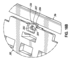
本明細書において説明されている任意の例示的な壊れやすいコネクタは、コネクタのどのコンポーネントが最初に破断するか、および/または破断の位置など、特定の故障モードを促すように配置構成された1つまたは複数の応力集中部を含み得る。図16は、フランジ384内の、例示的な応力集中部、具体的にはノッチ385を例示している。ステージング時に(たとえば、第1の位置から第2の位置への移動時に)、ノッチ385は、フランジ384の破断を促し、それによって、フレーム314の周辺部分316からの蓋318の予測可能で一貫した分離を円滑にし得る。
Any of the example frangible connectors described herein may include one or more stress concentrators arranged to encourage a particular failure mode, such as which component of the connector breaks first and/or the location of the break. FIG. 16 illustrates an example stress concentrator, specifically a
図15を再び参照すると、周辺部分316は、フランジ31などの、フレーム閉鎖要素を伴う、ラッチ25などの、周辺部分閉鎖要素の係合を通じて閉位置(たとえば、図3Bに類似する)にスナップ式に嵌合する。アセンブリ300において、ラッチ25は、側面囲壁316b、316dから延在し、対応するフランジ31は、側面囲外壁314b、314dに配設される。様々な実施形態において、側面壁上の閉鎖要素(たとえば、ラッチ25およびフランジ31)は、端壁上の閉鎖要素(たとえば、アセンブリ10のラッチ24、26およびフランジ30、32)に加えて、またはその代わりに提供され得る。
Referring again to FIG. 15, the
本発明は特定の実施形態の説明により例示され、実施形態は相当詳細に説明されているが、付属の請求項の範囲をそのような詳細に制限するか、またはどのような形であれ限定することは意図されていない。本明細書で説明されている様々な特徴は、単独で、または様々な実施形態の中の、および様々な実施形態の間の任意の組合せで使用されてよい。追加の利点および修正は、当業者が容易に思いつくものである。したがって、本発明はそのより広い態様において、図示し説明されている特定の詳細、代表的な装置および方法、ならびに説明に役立つ例に限定されない。したがって、一般的な発明の概念の範囲または精神から逸脱することなく、そのような詳細からの逸脱を行うことができる。 While the present invention has been illustrated by the description of certain embodiments, and the embodiments have been described in considerable detail, it is not intended to restrict or in any way limit the scope of the appended claims to such details. The various features described herein may be used alone or in any combination within and between the various embodiments. Additional advantages and modifications will readily occur to those skilled in the art. Thus, the invention in its broader aspects is not limited to the specific details, representative apparatus and methods, and illustrative examples shown and described. Accordingly, departures may be made from such details without departing from the scope or spirit of the general inventive concept.
10 アセンブリ
11 内部
12 組織試料カセット
12a 側壁
12b 底壁
14 フレーム
14a、14b、14c、14d 囲外壁
14e 底縁
16 周辺部分
16a、16b、16c、16d 囲側壁
18 蓋
22a、22b ヒンジ
24、26 ラッチ
30、32 フランジ
36 蓋フレームコネクタ
38 保持フランジ
40 カセット位置決め要素
42 弾力性のある指
42a 遠位端
42b 歯
44 包埋された組織試料
46 対角ストッパー
48 ステージングデバイス
50 包埋パラフィン蝋
52 包埋モールド
58 フランジ
60 ラッチ
64 フレームカセットコネクタ
66 ピン
68 フランジ
70 タブ
72 基部
74 先端部
76 シャフト
80 シャフト幅
82 ピン
84 フランジ
86 タブ
88 基部
90 先端部
92 シャフト
94 先端幅
96 シャフト幅
98 工具
100 アセンブリ
111 陥凹部または内部領域
112 組織試料カセット
112a 側壁
112b 底壁
114 フレーム
114a、114b、114c、114d 囲外壁
114e 底縁
116 周辺部分
116a、116b、116c、116d 囲(周辺)壁
117 周辺部分
118 蓋
120 付勢部材
122a、122b ヒンジ
124、126 ラッチ
130、132 フランジ
136 蓋フレームコネクタ
138 蓋保持フランジ
140 カセット位置決め要素
142 ほぼ矩形のプラテン
146 下方に離間する対角ストッパー
158 ラッチ
159 アーム
160 フランジ
164 フレームカセットコネクタ
200 アセンブリ
211 陥凹部または内部領域
212 組織試料カセット
212a 側壁
212b 底壁
214 フレーム
214a、214b、214c、214d 囲外壁
214e 底縁
216 周辺部分
216a、216b、216c、216d 囲(周辺)壁
218 蓋
220 ほぼ螺旋状の付勢部材
222a、222b ヒンジ
224、226 ラッチ
230、232 フランジ
236 蓋フレームコネクタ
238 蓋保持フランジ
240 カセット位置決め要素
242 ほぼ円形のプラテン
242b 歯
246 対角ストッパー
258 ラッチ
259 アーム
260 フランジ
264 フレームカセットコネクタ
300 アセンブリ
312 組織試料カセット
314 フレーム
314a、314b、314c、314d 囲外壁
314b、314d 側面囲外壁
316 周辺部分
316a、316b、316c、316d 囲(周辺)壁
318 蓋
336 蓋フレームコネクタ
364 フレームカセットコネクタ
366 ピン
368 フランジ
370 タブ
382 ピン
384 フランジ
385 ノッチ
386 タブ
385 応力集中部
600 ピン/フランジコネクタ
602 ピン
604 第1のコンポーネント
606 フランジ
608 第2のコンポーネント
610 キャビティ
612 モールド/工具
614 幅広のトラス頭形状の先端部
700 ピン/フランジコネクタ
702 第1のコンポーネント
704 陥凹部
706 ピン
708 陥凹部
710 工具
712 先端部
714 中央突出部
716 第2のコンポーネント
750 ピン/フランジコネクタ
752 第1のコンポーネント
754 陥凹部
756 ピン
766 第2のコンポーネント
10 Assembly
11. Inside
12 Tissue Sample Cassette
12a Side Wall
12b Bottom wall
14 Frame
14a, 14b, 14c, 14d Enclosure walls
14e Bottom edge
16 Periphery
16a, 16b, 16c, 16d Enclosure side walls
18 Lid
22a, 22b hinge
24, 26 Latch
30, 32 flange
36 Lid Frame Connector
38 Retaining flange
40 Cassette positioning element
42 Elastic Fingers
42a Distal end
42b Teeth
44 Embedded tissue samples
46 Diagonal stopper
48 Staging Devices
50 Embedding Paraffin Wax
52 Embedding Mold
58 Flange
60 Latch
64 Frame Cassette Connector
66 pin
68 Flange
70 Tabs
72 Base
74 Tip
76 Shaft
80 Shaft width
82 pin
84 Flange
86 Tabs
88 Base
90 Tip
92 Shaft
94 Tip width
96 Shaft width
98 Tools
100 Assembly
111 Recessed or internal areas
112 Tissue Sample Cassette
112a Side wall
112b Bottom wall
114 Frames
114a, 114b, 114c, 114d Enclosure walls
114e Bottom edge
116 Periphery
116a, 116b, 116c, 116d Surrounding walls
117 Periphery
118 Lid
120 biasing member
122a, 122b hinge
124, 126 Latch
130, 132 flange
136 Lid frame connector
138 Lid Retaining Flange
140 Cassette positioning element
142 Nearly rectangular platen
146 Diagonal stopper spaced downwards
158 Latch
159 Arm
160 Flange
164 Frame Cassette Connector
200 Assembly
211 Recessed or internal areas
212 Tissue Sample Cassette
212a Side wall
212b Bottom wall
214 Frames
214a, 214b, 214c, 214d Enclosure walls
214e Bottom edge
216 Periphery
216a, 216b, 216c, 216d Surrounding walls
218 Lid
220 A substantially helical biasing member
222a, 222b hinge
224, 226 Latch
230, 232 flange
236 Lid Frame Connector
238 Lid Retaining Flange
240 Cassette Positioning Element
242 Nearly circular platen
242b Teeth
246 Diagonal Stopper
258 Latch
259 Arm
260 Flange
264 Frame Cassette Connector
300 Assembly
312 Tissue Sample Cassette
314 Frames
314a, 314b, 314c, 314d Enclosure walls
314b, 314d Side enclosure wall
316 Periphery
316a, 316b, 316c, 316d Surrounding (perimeter) walls
318 Lid
336 Lid Frame Connector
364 Frame Cassette Connector
366 Pins
368 Flange
370 tabs
382 Pins
384 Flange
385 Notch
386 tabs
385 Stress concentration area
600 pin/flange connector
602 Pin
604 First Component
606 Flange
608 Second Component
610 Cavity
612 Molds/Tools
614 Wide truss head shaped tip
700 pin/flange connector
702 First Component
704 Depression
706 Pins
708 Depression
710 Tools
712 Tip
714 Central protrusion
716 Second Component
750 Pin/Flange Connector
752 First Component
754 Depression
756 Pins
766 Second Component
Claims (39)
少なくとも1つの側壁と底壁とを備える陥凹部を有する組織カセットであって、前記組織カセットはミクロトームでの薄切りに成功し得る第1の材料から形成され、組織を固定し、処理し、染色するために使用される溶媒および化学薬品による劣化に強い、組織カセットと、
底縁を備えるフレームであって、前記フレームは前記第1の材料と異なる、また前記第1の材料よりも剛性が高い、第2の材料から形成され、前記組織カセットは前記カセットと一体形成された第2の保持構造を通って少なくとも途中まで延在する前記フレームと一体形成された第1の保持構造を備えるフレームカセットコネクタによって前記フレームに結合される、フレームと、
前記フレームに結合されている蓋とを備え、
前記蓋および前記組織カセットは、前記フレームに関して第1の位置から第2の位置に移動することができ、前記第2の位置において、前記底壁および前記側壁の少なくとも一部は、前記ミクロトームで薄切りするために前記フレームの前記底縁を越えて下方に延在し、
前記フレームは、前記フレームカセットコネクタを分離することによって前記カセットから切り離すことができ、
前記第1の保持構造は、前記フレームと一体形成されたピンを備え、前記第2の保持構造は、前記カセットと一体形成されたフランジを備える、組織学的組織試料支持デバイス。 1. A histological tissue sample support device comprising:
a tissue cassette having a recess with at least one side wall and a bottom wall, said tissue cassette being formed from a first material that can be successfully sectioned in a microtome and that is resistant to degradation by solvents and chemicals used to fix, process and stain the tissue;
a frame having a bottom edge, the frame being formed from a second material different from and more rigid than the first material, the tissue cassette being coupled to the frame by a frame cassette connector comprising a first retaining structure integral with the frame that extends at least part way through a second retaining structure integral with the cassette;
a lid coupled to the frame;
the lid and the tissue cassette are movable from a first position to a second position relative to the frame, and in the second position, at least a portion of the bottom wall and the side wall extend downwardly beyond the bottom edge of the frame for slicing with the microtome;
the frame can be separated from the cassette by separating the frame-cassette connectors ;
A histological tissue sample support device, wherein the first retaining structure comprises a pin integrally formed with the frame and the second retaining structure comprises a flange integrally formed with the cassette .
前記フレームと一体形成された前記ピンは、前記複数の外壁のうちの1つからほぼ横方向内向きに延在するタブ上に配設される請求項1に記載の支持デバイス。 the frame further comprises a plurality of outer walls extending generally upwardly from the bottom edge;
The support device of claim 1 , wherein the pin integral with the frame is disposed on a tab extending generally laterally inward from one of the outer walls.
前記先端幅は、前記シャフト幅より大きい請求項1に記載の支持デバイス。 the pin formed integrally with the frame includes a base portion, a tip portion having a tip width, and a shaft having a shaft width and extending from the base portion to the tip portion;
The support device of claim 1 , wherein the tip width is greater than the shaft width.
少なくとも1つの側壁と底壁とを備える陥凹部を有する組織カセットであって、前記組織カセットはミクロトームでの薄切りに成功し得る第1の材料から形成され、組織を固定し、処理し、染色するために使用される溶媒および化学薬品による劣化に強い、組織カセットと、
底縁を備えるフレームであって、前記フレームは前記第1の材料と異なる、また前記第1の材料よりも剛性が高い、第2の材料から形成され、前記組織カセットは前記カセットと一体形成された第2の保持構造を通って少なくとも途中まで延在する前記フレームと一体形成された第1の保持構造を備えるフレームカセットコネクタによって前記フレームに結合される、フレームと、
前記フレームに結合されている蓋とを備え、
前記蓋および前記組織カセットは、前記フレームに関して第1の位置から第2の位置に移動することができ、前記第2の位置において、前記底壁および前記側壁の少なくとも一部は、前記ミクロトームで薄切りするために前記フレームの前記底縁を越えて下方に延在し、
前記フレームは、前記フレームカセットコネクタを分離することによって前記カセットから切り離すことができ、
前記蓋は、前記蓋と一体形成された第4の保持構造を通って少なくとも途中まで延在する前記フレームの周辺部分と一体形成された第3の保持構造を備える蓋フレームコネクタによって前記フレームに結合され、
前記蓋は、前記蓋フレームコネクタを分離することによって前記フレームの前記周辺部分から切り離すことができ、
前記第3の保持構造は、前記フレームの前記周辺部分と一体形成されたピンを備え、前記第4の保持構造は、前記蓋と一体形成されたフランジを備える、支持デバイス。 1. A histological tissue sample support device comprising:
a tissue cassette having a recess with at least one side wall and a bottom wall, said tissue cassette being formed from a first material that can be successfully sectioned in a microtome and that is resistant to degradation by solvents and chemicals used to fix, process and stain the tissue;
a frame having a bottom edge, the frame being formed from a second material different from and more rigid than the first material, the tissue cassette being coupled to the frame by a frame cassette connector comprising a first retaining structure integral with the frame that extends at least part way through a second retaining structure integral with the cassette;
a lid coupled to the frame;
the lid and the tissue cassette are movable from a first position to a second position relative to the frame, and in the second position, at least a portion of the bottom wall and the side wall extend downwardly beyond the bottom edge of the frame for slicing with the microtome;
the frame can be separated from the cassette by separating the frame-cassette connectors;
the lid is coupled to the frame by a lid frame connector including a third retention structure integral with a peripheral portion of the frame that extends at least part way through a fourth retention structure integral with the lid;
the lid can be separated from the peripheral portion of the frame by separating the lid-frame connector;
A support device , wherein the third retention structure comprises a pin integrally formed with the peripheral portion of the frame and the fourth retention structure comprises a flange integrally formed with the lid.
前記周辺部分と一体形成された前記ピンは、前記複数の周壁のうちの1つからほぼ横方向内向きに延在するタブ上に配設される請求項10に記載の支持デバイス。 the peripheral portion of the frame includes a plurality of peripheral walls surrounding the lid;
The support device of claim 10 , wherein the pin integral with the peripheral portion is disposed on a tab extending generally laterally inward from one of the peripheral walls.
前記カセット閉鎖要素は、前記第3のコネクタに係合するように配置構成された第4のコネクタをさらに備え、前記第2のコネクタおよび前記第4のコネクタはほぼ横方向に配向されている請求項20に記載の支持デバイス。 the lid closure element further comprises a third connector disposed on a second elongated arm, the first elongated arm and the second elongated arm projecting generally downwardly from the lid when the lid is in a closed configuration on the cassette, the first elongated arm and the second elongated arm being disposed on the lid in a spaced apart opposing arrangement such that the first connector faces away from the third connector;
21. The support device of claim 20, wherein the cassette closure element further comprises a fourth connector configured to engage with the third connector, the second connector and the fourth connector being oriented generally laterally.
前記第2のコネクタは、ほぼ横方向に配向され、前記第1のコネクタおよび前記第3のコネクタに係合するように配置構成される請求項20に記載の支持デバイス。 the lid closure element further comprises a third connector disposed on a second elongated arm, the first elongated arm and the second elongated arm projecting generally downwardly from the lid when the lid is in a closed configuration on the cassette, the first elongated arm and the second elongated arm being disposed on the lid in an opposing arrangement such that the first connector faces toward the third connector;
21. The support device of claim 20 , wherein the second connector is oriented generally laterally and configured to engage the first connector and the third connector.
前記フレームは、ヒンジによって前記複数の外壁のうちの1つに結合された周辺部分をさらに備え、
前記組織カセットは、前記複数の外壁のうちの1つに結合され、前記蓋は、前記周辺部分に結合され、
前記複数の外壁の少なくとも1つは、フレーム閉鎖要素を備え、前記周辺部分は、周辺部分閉鎖要素を備え、前記フレーム閉鎖要素および前記周辺部分閉鎖要素は閉鎖構成で係合されたときに前記周辺部分を前記複数の外壁に固定するように構成される請求項1又は10に記載の支持デバイス。 the frame further comprises a plurality of outer walls extending generally upwardly from the bottom edge;
the frame further comprising a peripheral portion coupled to one of the outer walls by a hinge;
the tissue cassette is coupled to one of the plurality of outer walls and the lid is coupled to the peripheral portion;
11. The support device of claim 1 or 10, wherein at least one of the plurality of outer walls comprises a frame closure element and the peripheral portion comprises a peripheral portion closure element, the frame closure element and the peripheral portion closure element configured to secure the peripheral portion to the plurality of outer walls when engaged in a closed configuration.
少なくとも1つの側壁と底壁とを備える陥凹部を有する組織カセットを成形するステップであって、前記組織カセットはミクロトームでの薄切りに成功し得る第1の材料から形成され、組織を固定し、処理し、染色するために使用される溶媒および化学薬品による劣化に強い、ステップと、
底縁を備えるフレームを成形するステップであって、前記フレームは前記第1の材料と異なる、また前記第1の材料よりも剛性が高い、第2の材料から形成される、ステップと、
前記組織カセットを、前記カセットと一体形成された第2の保持構造を通って少なくとも途中まで延在する前記フレームと一体形成された第1の保持構造を備えるフレームカセットコネクタを組み立てることによって前記フレームに結合するステップであって、前記フレームは、前記フレームカセットコネクタを分離することによって前記カセットから切り離すことができる、ステップとを含み、
前記第1の保持構造は、前記フレームと一体形成されたピンを備え、前記第2の保持構造は、前記カセットと一体形成されたフランジを備える、方法。 1. A method for manufacturing an apparatus for holding a histological tissue sample while the tissue sample is sliced in a microtome, comprising the steps of:
molding a tissue cassette having a recess with at least one side wall and a bottom wall, said tissue cassette being formed from a first material that can be successfully sectioned in a microtome and that is resistant to degradation by solvents and chemicals used to fix, process and stain tissue;
molding a frame having a bottom edge, the frame being formed from a second material that is different from and more rigid than the first material;
coupling the tissue cassette to the frame by assembling a frame-cassette connector comprising a first retaining structure integral with the frame extending at least part way through a second retaining structure integral with the cassette, the frame being separable from the cassette by separating the frame-cassette connector ;
The method , wherein the first retention structure comprises a pin integrally formed with the frame and the second retention structure comprises a flange integrally formed with the cassette .
少なくとも1つの側壁と底壁とを備える陥凹部を有する組織カセットを成形するステップであって、前記組織カセットはミクロトームでの薄切りに成功し得る第1の材料から形成され、組織を固定し、処理し、染色するために使用される溶媒および化学薬品による劣化に強い、ステップと、
底縁を備えるフレームを成形するステップであって、前記フレームは前記第1の材料と異なる、また前記第1の材料よりも剛性が高い、第2の材料から形成される、ステップと、
前記組織カセットを、前記カセットと一体形成された第2の保持構造を通って少なくとも途中まで延在する前記フレームと一体形成された第1の保持構造を備えるフレームカセットコネクタを組み立てることによって前記フレームに結合するステップであって、前記フレームは、前記フレームカセットコネクタを分離することによって前記カセットから切り離すことができる、ステップと、
蓋を成形するステップと、
前記蓋を、前記蓋と一体形成された第4の保持構造を通って少なくとも途中まで延在する前記フレームの周辺部分と一体形成された第3の保持構造を備える蓋フレームコネクタを組み立てることによって前記フレームに結合するステップであって、前記蓋は、前記蓋フレームコネクタを分離することによって前記カセットの前記周辺部分から切り離すことができる、ステップとを含み、
前記第3の保持構造は、前記フレームの前記周辺部分と一体形成されたピンを備え、前記第4の保持構造は、前記蓋と一体形成されたフランジを備える、方法。 1. A method for manufacturing an apparatus for holding a histological tissue sample while the tissue sample is sliced in a microtome, comprising the steps of:
molding a tissue cassette having a recess with at least one side wall and a bottom wall, said tissue cassette being formed from a first material that can be successfully sectioned in a microtome and that is resistant to degradation by solvents and chemicals used to fix, process and stain tissue;
molding a frame having a bottom edge, the frame being formed from a second material that is different from and more rigid than the first material;
coupling the tissue cassette to the frame by assembling a frame-cassette connector comprising a first retaining structure integral with the frame that extends at least part way through a second retaining structure integral with the cassette, the frame being separable from the cassette by separating the frame-cassette connector;
forming a lid;
coupling the lid to the frame by assembling a lid frame connector comprising a third retention structure integral with a peripheral portion of the frame that extends at least part way through a fourth retention structure integral with the lid, the lid being separable from the peripheral portion of the cassette by separating the lid frame connector;
The method of claim 1, wherein the third retention structure comprises a pin integrally formed with the peripheral portion of the frame and the fourth retention structure comprises a flange integrally formed with the lid .
組織試料を少なくとも1つの側壁および底壁を備える陥凹部を有する組織カセット内に位置決めするステップであって、前記組織カセットはミクロトームでの薄切りに成功し得る第1の材料から形成され、組織を固定し、処理し、染色するために使用される溶媒および化学薬品による劣化に強く、前記組織カセットは底縁を備えるフレーム内に配設され、前記組織カセットは前記カセットと一体形成された第2の保持構造を通って延在する前記フレームと一体形成された第1の保持構造を備えるフレームカセットコネクタによってフレームに結合される、ステップと、
前記フレームの周辺部分を閉鎖するステップであって、前記フレームの前記周辺部分は中に配設されているカセット蓋を備える、ステップと、
前記フレームカセットコネクタを破断することを含む前記蓋および前記組織カセットを前記フレームに関して第1の位置から第2の位置に移動するステップであって、前記第2の位置において、前記底壁、および前記側壁の少なくとも一部は、前記ミクロトームで薄切りするために前記フレームの前記底縁を越えて下方に延在する、ステップとを含み、
前記第1の保持構造は、前記フレームと一体形成されたピンを備え、前記第2の保持構造は、前記カセットと一体形成されたフランジを備える、方法。 1. A method of preparing one or more biopsy tissue samples for histological examination, comprising the steps of:
positioning a tissue sample in a tissue cassette having a recess with at least one side wall and a bottom wall, the tissue cassette formed from a first material that can be successfully sectioned in a microtome and that is resistant to degradation by solvents and chemicals used to fix, process and stain tissue, the tissue cassette disposed in a frame having a bottom edge, the tissue cassette coupled to the frame by a frame cassette connector comprising a first retaining structure integral with the frame extending through a second retaining structure integral with the cassette;
closing a peripheral portion of the frame, the peripheral portion of the frame having a cassette lid disposed therein;
moving the lid and the tissue cassette from a first position to a second position with respect to the frame, including breaking the frame-cassette connector, wherein in the second position the bottom wall and at least a portion of the side walls extend downwardly beyond the bottom edge of the frame for slicing with the microtome ;
The method , wherein the first retention structure comprises a pin integrally formed with the frame and the second retention structure comprises a flange integrally formed with the cassette .
組織試料を少なくとも1つの側壁および底壁を備える陥凹部を有する組織カセット内に位置決めするステップであって、前記組織カセットはミクロトームでの薄切りに成功し得る第1の材料から形成され、組織を固定し、処理し、染色するために使用される溶媒および化学薬品による劣化に強く、前記組織カセットは底縁を備えるフレーム内に配設され、前記組織カセットは前記カセットと一体形成された第2の保持構造を通って延在する前記フレームと一体形成された第1の保持構造を備えるフレームカセットコネクタによってフレームに結合される、ステップと、
前記フレームの周辺部分を閉鎖するステップであって、前記フレームの前記周辺部分は中に配設されているカセット蓋を備える、ステップと、
前記フレームカセットコネクタを破断することを含む前記蓋および前記組織カセットを前記フレームに関して第1の位置から第2の位置に移動するステップであって、前記第2の位置において、前記底壁、および前記側壁の少なくとも一部は、前記ミクロトームで薄切りするために前記フレームの前記底縁を越えて下方に延在する、ステップとを含み、
前記移動の操作は、前記蓋と一体形成された第4の保持構造を通って延在する前記フレームの前記周辺部分と一体形成された第3の保持構造を備える蓋フレームコネクタを破断するステップを含み、
前記第3の保持構造は、前記フレームの前記周辺部分と一体形成されたピンを備え、前記第4の保持構造は、前記蓋と一体形成されたフランジを備える、方法。 1. A method of preparing one or more biopsy tissue samples for histological examination, comprising the steps of:
positioning a tissue sample in a tissue cassette having a recess with at least one side wall and a bottom wall, the tissue cassette formed from a first material that can be successfully sectioned in a microtome and that is resistant to degradation by solvents and chemicals used to fix, process and stain tissue, the tissue cassette disposed in a frame having a bottom edge, the tissue cassette coupled to the frame by a frame cassette connector comprising a first retaining structure integral with the frame extending through a second retaining structure integral with the cassette;
closing a peripheral portion of the frame, the peripheral portion of the frame having a cassette lid disposed therein;
moving the lid and the tissue cassette from a first position to a second position with respect to the frame, including breaking the frame-cassette connector, wherein in the second position the bottom wall and at least a portion of the side walls extend downwardly beyond the bottom edge of the frame for slicing with the microtome;
the moving operation includes breaking a lid frame connector including a third retention structure integral with the peripheral portion of the frame extending through a fourth retention structure integral with the lid;
The method of claim 1, wherein the third retention structure comprises a pin integrally formed with the peripheral portion of the frame and the fourth retention structure comprises a flange integrally formed with the lid .
前記蓋は、前記第1の材料から形成される請求項36又は37に記載の方法。 the frame is formed from a second material that is different from and more rigid than the first material;
38. A method according to claim 36 or 37 , wherein the lid is formed from the first material.
Priority Applications (1)
| Application Number | Priority Date | Filing Date | Title |
|---|---|---|---|
| JP2024190968A JP2025026867A (en) | 2019-11-12 | 2024-10-30 | Slicable cassette with connector and embedding frame and method for preparing biopsy tissue samples - Patents.com |
Applications Claiming Priority (3)
| Application Number | Priority Date | Filing Date | Title |
|---|---|---|---|
| US16/680,601 US11498077B2 (en) | 2019-11-12 | 2019-11-12 | Sectionable cassette and embedding frame with connectors, and methods for preparing biopsy tissue samples |
| US16/680,601 | 2019-11-12 | ||
| PCT/US2020/059455 WO2021096779A1 (en) | 2019-11-12 | 2020-11-06 | Sectionable cassette and embedding frame with connectors, and methods for preparing biopsy tissue samples |
Related Child Applications (1)
| Application Number | Title | Priority Date | Filing Date |
|---|---|---|---|
| JP2024190968A Division JP2025026867A (en) | 2019-11-12 | 2024-10-30 | Slicable cassette with connector and embedding frame and method for preparing biopsy tissue samples - Patents.com |
Publications (2)
| Publication Number | Publication Date |
|---|---|
| JP2023502592A JP2023502592A (en) | 2023-01-25 |
| JP7581350B2 true JP7581350B2 (en) | 2024-11-12 |
Family
ID=75847471
Family Applications (2)
| Application Number | Title | Priority Date | Filing Date |
|---|---|---|---|
| JP2022527205A Active JP7581350B2 (en) | 2019-11-12 | 2020-11-06 | Slicable cassette with connector and embedding frame and method for preparing biopsy tissue samples - Patents.com |
| JP2024190968A Pending JP2025026867A (en) | 2019-11-12 | 2024-10-30 | Slicable cassette with connector and embedding frame and method for preparing biopsy tissue samples - Patents.com |
Family Applications After (1)
| Application Number | Title | Priority Date | Filing Date |
|---|---|---|---|
| JP2024190968A Pending JP2025026867A (en) | 2019-11-12 | 2024-10-30 | Slicable cassette with connector and embedding frame and method for preparing biopsy tissue samples - Patents.com |
Country Status (10)
| Country | Link |
|---|---|
| US (5) | US11498077B2 (en) |
| EP (2) | EP4058193B1 (en) |
| JP (2) | JP7581350B2 (en) |
| CN (2) | CN118477707A (en) |
| AU (2) | AU2020382761B2 (en) |
| BR (1) | BR112022008992A2 (en) |
| CA (1) | CA3158946A1 (en) |
| DK (1) | DK4058193T3 (en) |
| ES (1) | ES2995235T3 (en) |
| WO (1) | WO2021096779A1 (en) |
Families Citing this family (12)
| Publication number | Priority date | Publication date | Assignee | Title |
|---|---|---|---|---|
| US11498077B2 (en) | 2019-11-12 | 2022-11-15 | Biopath Automation, Llc | Sectionable cassette and embedding frame with connectors, and methods for preparing biopsy tissue samples |
| WO2022261938A1 (en) * | 2021-06-18 | 2022-12-22 | Leica Biosystems Nussloch Gmbh | Cassette for holding and orienting tissue sample |
| US20240286133A1 (en) * | 2021-06-18 | 2024-08-29 | Leica Biosystems Nussloch Gmbh | Cassette for holding and orienting tissue sample |
| EP4356103A4 (en) * | 2021-06-18 | 2025-03-05 | Leica Biosystems Nussloch GmbH | CASSETTE FOR CAPTURING AND ALIGNING A TISSUE SAMPLE |
| US20230149919A1 (en) * | 2021-11-15 | 2023-05-18 | Tissue Testing Technologies Llc | Cassette for preservation of natural and bioengineered tissues |
| CN118974535A (en) * | 2022-03-31 | 2024-11-15 | 莱卡生物系统努斯洛赫有限责任公司 | Device for pressing box and embedding machine having the same |
| US20240246079A1 (en) * | 2023-01-23 | 2024-07-25 | Cellpath Ltd | Cassette Assembly |
| WO2024207280A1 (en) * | 2023-04-06 | 2024-10-10 | Leica Biosystems Nussloch Gmbh | Cassette for auto-embedder |
| WO2024212121A1 (en) * | 2023-04-12 | 2024-10-17 | Leica Biosystems Nussloch Gmbh | Tissue cassette |
| WO2024221380A1 (en) * | 2023-04-28 | 2024-10-31 | Leica Biosystems Nussloch Gmbh | Tissue cassette and tissue embedding assembly |
| WO2025107254A1 (en) * | 2023-11-23 | 2025-05-30 | Leica Biosystems Nussloch Gmbh | Device for immobilizing multiple tissues for automated embedder |
| WO2025222364A1 (en) * | 2024-04-23 | 2025-10-30 | Leica Biosystems Nussloch Gmbh | Device for immobilizing tissue specimen or tissue specimens for automated embedder |
Citations (2)
| Publication number | Priority date | Publication date | Assignee | Title |
|---|---|---|---|---|
| JP2011503519A (en) | 2006-12-12 | 2011-01-27 | バイオパス・オートメーション・エル・エル・シー | Biopsy support with sectionable elastic foam material |
| JP2018526632A (en) | 2015-08-04 | 2018-09-13 | バイオパス・オートメーション・エル・エル・シー | Slicable cassette and embedded frame with tissue-fixable separable lid and method for preparing biopsy tissue samples |
Family Cites Families (51)
| Publication number | Priority date | Publication date | Assignee | Title |
|---|---|---|---|---|
| US4301814A (en) * | 1977-04-26 | 1981-11-24 | Meer Sneer | Cassette implant |
| US4421246A (en) | 1982-06-21 | 1983-12-20 | Allied Corporation | Biological tissue cassette |
| GB2127577B (en) * | 1982-09-20 | 1985-12-11 | V Tech Inc | Wet-mount microscopic examination slide |
| JPH0540449Y2 (en) * | 1987-10-14 | 1993-10-14 | ||
| US5127537A (en) | 1991-06-05 | 1992-07-07 | Graham Donald R | Tissue cassette with a living hinge |
| US5427742A (en) | 1994-04-26 | 1995-06-27 | Holland; Wayne | Tissue processing cassette |
| CA2117314C (en) * | 1994-06-09 | 1999-09-28 | Andre Lafond | Biological specimen cassette |
| JP3049537B2 (en) | 1995-02-03 | 2000-06-05 | 悌二 竹崎 | Fixation support method for biopsy sample, fixation support agent and embedding cassette |
| US5817032A (en) | 1996-05-14 | 1998-10-06 | Biopath Automation Llc. | Means and method for harvesting and handling tissue samples for biopsy analysis |
| CA2633945C (en) * | 1998-10-05 | 2010-07-13 | Biopath Automation, L.L.C. | Apparatus and method for harvesting and handling tissue samples for biopsy analysis |
| US20070166834A1 (en) | 1998-10-05 | 2007-07-19 | Biopath Automation, L.L.C. | Apparatus and method for harvesting and handling tissue samples for biopsy analysis |
| WO2000049392A1 (en) * | 1999-02-17 | 2000-08-24 | Lucid, Inc. | Cassette for facilitating optical sectioning of a retained tissue specimen |
| US6395234B1 (en) * | 2000-02-08 | 2002-05-28 | Triangle Biomedical Sciences, Inc. | Sample cassette having utility for histological processing of tissue samples |
| US6615763B2 (en) * | 2000-05-12 | 2003-09-09 | Innovative Science Limited | Printing on microscope slides and histology cassettes |
| DE20104158U1 (en) * | 2001-03-09 | 2001-08-02 | Leica Microsystems Nussloch GmbH, 69226 Nußloch | Cassette stack with cassettes for histological preparations |
| DE10115065A1 (en) * | 2001-03-27 | 2002-10-02 | Leica Microsystems | Method and device for printing on cassettes or slides for histological preparations |
| US6513673B2 (en) * | 2001-05-04 | 2003-02-04 | Kenneth A. Alley | Multiple-compartment biological specimen cassette |
| DE10223412B4 (en) * | 2002-05-25 | 2011-11-10 | Leica Biosystems Nussloch Gmbh | Tableau for holding cassettes and / or slides for histological or cytological preparations |
| US7179424B2 (en) | 2002-09-26 | 2007-02-20 | Biopath Automation, L.L.C. | Cassette for handling and holding tissue samples during processing, embedding and microtome procedures, and methods therefor |
| EP1545775B1 (en) * | 2002-09-26 | 2010-06-16 | BioPath Automation, L.L.C. | Cassette and embedding assembly, staging devices, and methods for handling tissue samples |
| US8043303B2 (en) * | 2002-10-04 | 2011-10-25 | Cook Medical Technologies Llc | Handle for interchangeable medical device |
| US20040166030A1 (en) * | 2003-02-26 | 2004-08-26 | Andre Lafond | Biological specimen cassette |
| DE10342264C5 (en) * | 2003-09-12 | 2012-10-31 | Leica Biosystems Nussloch Gmbh | System for uniquely assigning histological cassettes and slides |
| US20070116612A1 (en) | 2005-11-02 | 2007-05-24 | Biopath Automation, L.L.C. | Prefix tissue cassette |
| US7927564B2 (en) | 2005-12-19 | 2011-04-19 | Leica Biosystems Richmond, Inc. | Histological specimen cassette |
| US8162140B2 (en) | 2006-04-06 | 2012-04-24 | 2 View, Llc | Specimen retention container |
| EP2069750B1 (en) * | 2006-08-15 | 2014-07-02 | Cytyc Corporation | Cell block embedding system |
| US20080044895A1 (en) * | 2006-08-17 | 2008-02-21 | Oxyphen Ag | Filter support for use with a tissue cassette for collecting and embedding cells |
| US20110008884A1 (en) * | 2008-08-27 | 2011-01-13 | Morales Azorides R | Pathology grossing tool, cassette, and board |
| JP2010054480A (en) * | 2008-08-29 | 2010-03-11 | Seiko Instruments Inc | Embedding cassette printing apparatus |
| DE102008050530B4 (en) * | 2008-10-06 | 2012-01-19 | Leica Biosystems Nussloch Gmbh | A method for the common confusion-safe handling of slides and at least one sample cassette |
| BRPI1006958B1 (en) | 2009-01-22 | 2019-11-19 | Biopath Automation Llc | histological tissue specimen support and guidance devices and methods of preparing one or more elongated biopsy tissue samples for histological examination |
| US8241746B2 (en) * | 2009-01-28 | 2012-08-14 | Brady Worldwide, Inc. | Tissue cassette label |
| EP2616246A4 (en) * | 2010-09-13 | 2016-08-17 | Primera Technology Inc | Color printer system for histological specimen slides and cassettes |
| ITBO20110304A1 (en) * | 2011-05-26 | 2012-11-27 | Mario Cinti | MARKING EQUIPMENT FOR HISTOLOGICAL INCLUSION CASSETTE |
| US9546937B2 (en) | 2012-01-26 | 2017-01-17 | Richard-Allan Scientific Company | Tissue cassette assembly |
| US9801953B2 (en) * | 2012-10-15 | 2017-10-31 | Emory University | Nanoparticles carrying nucleic acid cassettes for expressing RNA |
| US9097629B2 (en) * | 2013-03-15 | 2015-08-04 | Leica Biosystems Nussloch Gmbh | Tissue cassette with retractable member |
| CA2845832C (en) * | 2013-03-15 | 2020-09-22 | Leica Biosystems Nussloch Gmbh | Tissue cassette with biasing element |
| FR3010818B1 (en) * | 2013-09-17 | 2016-12-09 | Dreampath Diagnostics | METHOD FOR DETECTING THE POSITION OF A CASSETTE AND ITS DEVICE |
| GB2518440B (en) * | 2013-09-23 | 2019-03-06 | Cellpath Ltd | Histology cassette with larger width and length dimensions |
| GB2518439B (en) * | 2013-09-23 | 2019-01-16 | Cellpath Ltd | Large Histology Processing Cassette |
| CN203908850U (en) | 2014-01-10 | 2014-10-29 | 刘勇 | Integrated pathological tissue embedding box |
| GB2523556A (en) * | 2014-02-26 | 2015-09-02 | Cellpath Ltd | Histology cassette stack |
| CN204855183U (en) | 2015-07-24 | 2015-12-09 | 南通大学附属医院 | Eyeball pathologic sampling mould |
| CN111417348A (en) * | 2017-08-29 | 2020-07-14 | 莱维特医疗公司 | Biopsy sample cassettes and related systems and methods |
| US12484884B2 (en) * | 2017-10-09 | 2025-12-02 | Sakura Finetek U.S.A., Inc. | Tissue cassette reader |
| US20190183465A1 (en) * | 2017-12-19 | 2019-06-20 | Devicor Medical Products, Inc. | Variable tissue collection and processing cassette |
| US11460382B2 (en) * | 2017-12-19 | 2022-10-04 | Devicor Medical Products, Inc. | Tissue collection and processing cassette |
| WO2019126180A1 (en) * | 2017-12-19 | 2019-06-27 | Devicor Medical Products, Inc. | Tissue collection and processing cassette with applied imaging |
| US11498077B2 (en) | 2019-11-12 | 2022-11-15 | Biopath Automation, Llc | Sectionable cassette and embedding frame with connectors, and methods for preparing biopsy tissue samples |
-
2019
- 2019-11-12 US US16/680,601 patent/US11498077B2/en active Active
-
2020
- 2020-11-06 EP EP20886503.0A patent/EP4058193B1/en active Active
- 2020-11-06 WO PCT/US2020/059455 patent/WO2021096779A1/en not_active Ceased
- 2020-11-06 JP JP2022527205A patent/JP7581350B2/en active Active
- 2020-11-06 ES ES20886503T patent/ES2995235T3/en active Active
- 2020-11-06 CN CN202410636846.8A patent/CN118477707A/en active Pending
- 2020-11-06 CA CA3158946A patent/CA3158946A1/en active Pending
- 2020-11-06 BR BR112022008992A patent/BR112022008992A2/en unknown
- 2020-11-06 EP EP24180996.1A patent/EP4425176A3/en active Pending
- 2020-11-06 DK DK20886503.0T patent/DK4058193T3/en active
- 2020-11-06 CN CN202080077716.5A patent/CN114728284B/en active Active
- 2020-11-06 AU AU2020382761A patent/AU2020382761B2/en active Active
-
2022
- 2022-10-17 US US17/967,485 patent/US12303904B2/en active Active
- 2022-10-20 US US17/970,042 patent/US11872565B2/en active Active
- 2022-10-20 US US17/970,031 patent/US20230041034A1/en active Pending
- 2022-10-20 US US17/970,007 patent/US20230040801A1/en active Pending
-
2024
- 2024-10-30 JP JP2024190968A patent/JP2025026867A/en active Pending
-
2025
- 2025-11-10 AU AU2025263893A patent/AU2025263893A1/en active Pending
Patent Citations (2)
| Publication number | Priority date | Publication date | Assignee | Title |
|---|---|---|---|---|
| JP2011503519A (en) | 2006-12-12 | 2011-01-27 | バイオパス・オートメーション・エル・エル・シー | Biopsy support with sectionable elastic foam material |
| JP2018526632A (en) | 2015-08-04 | 2018-09-13 | バイオパス・オートメーション・エル・エル・シー | Slicable cassette and embedded frame with tissue-fixable separable lid and method for preparing biopsy tissue samples |
Also Published As
| Publication number | Publication date |
|---|---|
| EP4058193A1 (en) | 2022-09-21 |
| US20230041994A1 (en) | 2023-02-09 |
| CN114728284B (en) | 2024-05-31 |
| US20230040801A1 (en) | 2023-02-09 |
| CN118477707A (en) | 2024-08-13 |
| US11872565B2 (en) | 2024-01-16 |
| US11498077B2 (en) | 2022-11-15 |
| CN114728284A (en) | 2022-07-08 |
| AU2020382761B2 (en) | 2025-09-04 |
| US12303904B2 (en) | 2025-05-20 |
| EP4058193A4 (en) | 2022-12-28 |
| EP4058193B1 (en) | 2024-10-09 |
| JP2023502592A (en) | 2023-01-25 |
| WO2021096779A1 (en) | 2021-05-20 |
| JP2025026867A (en) | 2025-02-26 |
| BR112022008992A2 (en) | 2022-10-25 |
| US20210138476A1 (en) | 2021-05-13 |
| AU2025263893A1 (en) | 2025-12-04 |
| AU2020382761A1 (en) | 2022-04-21 |
| ES2995235T3 (en) | 2025-02-07 |
| US20230035804A1 (en) | 2023-02-02 |
| EP4425176A3 (en) | 2024-11-20 |
| DK4058193T3 (en) | 2024-11-04 |
| CA3158946A1 (en) | 2021-05-20 |
| US20230041034A1 (en) | 2023-02-09 |
| EP4425176A2 (en) | 2024-09-04 |
Similar Documents
| Publication | Publication Date | Title |
|---|---|---|
| JP7581350B2 (en) | Slicable cassette with connector and embedding frame and method for preparing biopsy tissue samples - Patents.com | |
| JP7278348B2 (en) | Slicable Cassette and Embedding Frame with Tissue-fixing Separable Lid and Method for Preparing Biopsy Tissue Sample | |
| JP5259619B2 (en) | Biopsy support with sectionable elastic foam material | |
| AU2002341872B2 (en) | Cassette and embedding assembly, staging devices, and methods for handling tissue samples |
Legal Events
| Date | Code | Title | Description |
|---|---|---|---|
| A621 | Written request for application examination |
Free format text: JAPANESE INTERMEDIATE CODE: A621 Effective date: 20230920 |
|
| A977 | Report on retrieval |
Free format text: JAPANESE INTERMEDIATE CODE: A971007 Effective date: 20240405 |
|
| A131 | Notification of reasons for refusal |
Free format text: JAPANESE INTERMEDIATE CODE: A131 Effective date: 20240408 |
|
| A521 | Request for written amendment filed |
Free format text: JAPANESE INTERMEDIATE CODE: A523 Effective date: 20240705 |
|
| TRDD | Decision of grant or rejection written | ||
| A01 | Written decision to grant a patent or to grant a registration (utility model) |
Free format text: JAPANESE INTERMEDIATE CODE: A01 Effective date: 20240930 |
|
| A61 | First payment of annual fees (during grant procedure) |
Free format text: JAPANESE INTERMEDIATE CODE: A61 Effective date: 20241030 |
|
| R150 | Certificate of patent or registration of utility model |
Ref document number: 7581350 Country of ref document: JP Free format text: JAPANESE INTERMEDIATE CODE: R150 |