EP4484084A1 - Haarschneidegerät - Google Patents
Haarschneidegerät Download PDFInfo
- Publication number
- EP4484084A1 EP4484084A1 EP23182300.6A EP23182300A EP4484084A1 EP 4484084 A1 EP4484084 A1 EP 4484084A1 EP 23182300 A EP23182300 A EP 23182300A EP 4484084 A1 EP4484084 A1 EP 4484084A1
- Authority
- EP
- European Patent Office
- Prior art keywords
- cutter
- leaf spring
- cutter unit
- axis
- unit
- Prior art date
- Legal status (The legal status is an assumption and is not a legal conclusion. Google has not performed a legal analysis and makes no representation as to the accuracy of the status listed.)
- Pending
Links
Images


Classifications
-
- B—PERFORMING OPERATIONS; TRANSPORTING
- B26—HAND CUTTING TOOLS; CUTTING; SEVERING
- B26B—HAND-HELD CUTTING TOOLS NOT OTHERWISE PROVIDED FOR
- B26B19/00—Clippers or shavers operating with a plurality of cutting edges, e.g. hair clippers, dry shavers
- B26B19/02—Clippers or shavers operating with a plurality of cutting edges, e.g. hair clippers, dry shavers of the reciprocating-cutter type
- B26B19/04—Cutting heads therefor; Cutters therefor; Securing equipment thereof
- B26B19/046—Cutters being movable in the cutting head
-
- B—PERFORMING OPERATIONS; TRANSPORTING
- B26—HAND CUTTING TOOLS; CUTTING; SEVERING
- B26B—HAND-HELD CUTTING TOOLS NOT OTHERWISE PROVIDED FOR
- B26B19/00—Clippers or shavers operating with a plurality of cutting edges, e.g. hair clippers, dry shavers
- B26B19/02—Clippers or shavers operating with a plurality of cutting edges, e.g. hair clippers, dry shavers of the reciprocating-cutter type
- B26B19/04—Cutting heads therefor; Cutters therefor; Securing equipment thereof
- B26B19/06—Cutting heads therefor; Cutters therefor; Securing equipment thereof involving co-operating cutting elements both of which have shearing teeth
- B26B19/063—Movable or adjustable cutting head
-
- B—PERFORMING OPERATIONS; TRANSPORTING
- B26—HAND CUTTING TOOLS; CUTTING; SEVERING
- B26B—HAND-HELD CUTTING TOOLS NOT OTHERWISE PROVIDED FOR
- B26B19/00—Clippers or shavers operating with a plurality of cutting edges, e.g. hair clippers, dry shavers
- B26B19/28—Drive layout for hair clippers or dry shavers, e.g. providing for electromotive drive
Definitions
- the present invention relates to cutting body hair such as beard stubbles. More particularly, the present invention relates to a hair cutter such as an electric shaver and/or trimmer, comprising a handle and a cutter head attached thereto, and at least one cutter unit including a pair of drivable and stationary cutter elements cooperating with each other, said cutter unit being adjustably supported by means of a support structure including a spring mechanism to allow for self-adaption of the cutter unit to the skin contour in terms of diving and/or tilting of the cutter unit relative to a cutter head frame, said spring mechanism including at least one elongated leaf spring.
- a hair cutter such as an electric shaver and/or trimmer
- Electric shavers and trimmers utilize various mechanisms to provide hair cutting functionality.
- Some electric shavers use one or more cutter units including a perforated shear foil cooperating with an undercutter movable relative thereto so as to cut hairs entering the perforations in the shear foil.
- Such shear foil type shavers are often used on a daily basis to provide for a clean shave wherein short beard stubbles are cut immediately at the skin surface.
- cutter units including a pair of cooperating cutting elements with comb-like edges including one or more rows of comb-like or rake-like cutting teeth reciprocating or rotating relative to each other, are often used for cutting longer beard stubbles or problem hair that is difficult to cut due to, for example, a very small angle to the skin or growing from very resilient skin.
- the teeth of such comb-like or rake-like cutting elements usually project substantially parallel to each other or substantially radially, depending on the type of driving motion, and may cut hairs entering into the gaps between the cutting teeth, wherein cutting or shearing is achieved in a scissor-like way when the cutting teeth of the cooperating elements close the gap between the finger-like cutting teeth and pass over each other.
- Such cutter units for longer hairs may be integrated into electric shavers or trimmers which at the same time may be provided with the aforementioned shear foil cutter units.
- a cutter head may include one or two cutter units with comb-like cutting teeth and, for example, at opposite sides of such comb-like cutters a pair of cutting units of the shear foil type, wherein, however, other arrangements and combinations may be used.
- a well-set and close-fitting skin contact without undue skin contact pressure helps to achieve an efficient cutting action and to avoid skin irritations
- a resilient support structure allowing for self-adaption of the cutter units to the skin contour may be used to achieve such goals.
- the entire cutter head may be movably supported by the handle head portion to allow swiveling and/or tilting and or diving of the cutter elements such as the shear foil and/or the comb-like blades relative to the handle head portion.
- Such swiveling and/or tilting of the cutter head allows the skin contact surface of the cutter head to smoothly follow the skin contour and compensate misalignment or misorientation of the handle.
- the cutter units may be movably supported relative to a cutter head frame to allow for further adapting movements of the cutter units relative to the cutter head frame, in addition to or in the alternative to adapting movements of the entire cutter head relative to the handle.
- Such additional self-adaption in terms of movability of the cutter units relative to the cutter head frame is in particular helpful when more than one cutter unit is provided at the cutter head, wherein the support structure for movably supporting the cutter units relative to the cutter head frame may allow for individual movements of the cutter units relative to each other and relative to the cutter head frame.
- a leading cutter unit may contact a skin portion differently inclined or curved than a skin portion touched by a trailing cutter unit so a better adaption to the skin contour may be achieved when the leading cutter unit tilts or dives in a way different from tilting or diving of the trailing cutter unit.
- the support structure allowing for self-adaption movements of the cutter units relative to the cutter head frame may be configured to allow for diving of one or more cutter units along one or more diving axes substantially perpendicular to the skin contact surface of the cutter head and cutter units, respectively, and/or allow for tilting of one or more cutter units about one or more tilt axes extending substantially parallel to said skin contact surface and perpendicular to a longitudinal or main axis of the respective cutter unit. More particularly, such tilt axes may extend substantially perpendicular to the usual travelling axes of the cutter head along the skin surface when the hair cutter is used in a usual way to effect cutting action.
- Such individual diving and/or tilting of the cutter units relative to the cutter head frame is sometimes called microdiving and microtilting.
- the cutter units usually include a stationary cutter element and a drivable cutter element which is driven to reciprocate or rotatorily oscillate relative to the stationary cutter element.
- a stiff, rigid support of the stationary cutting element is desired with regard to the driving axis, so the stationary cutting element does not follow movements of the driven cutting element along said driving axis, whereas on the other hand the cutter unit including the stationary cutting element should be easily movable to tilt and/or dive with limited resistance and/or limited restoring forces to allow for light footed self-adaption.
- the support structure supporting the cutter units needs to fulfill quite diverging demands:
- the support structure should be stiff and rigid, whereas the support structure should be soft and resilient with regard to the tilt and/or dive axis.
- Such underlying problem is intensified due to the fact that the drivable and stationary cutter elements cooperating with each other usually need some contact pressure and/or closeness to each other to achieve efficient shearing and cutting of the hair stubbles.
- a biasing mechanism is provided for urging the cooperating cutter elements against each other, wherein the biasing mechanism should not impair the self-adaption movements.
- such biasing mechanism includes a spring mechanism applying a spring force onto one of the cutting elements to urge it against the other cutter element cooperating therewith.
- the stationary cutter element should be held rigidly against movements along or about the driving axis of the driving mechanism to achieve efficient driving.
- the support structure usually includes additional support elements such as guide pins received in slot-like pockets to fixedly hold the stationary cutter element in the direction of the driving movements such as reciprocating movements, but allowing for tilting and/or diving.
- such guide pins should have a tight fit in such pockets, whereas, however, such tight fit makes the support structure sluggish and rough-running with regard to self-adaption movements such as diving and/or tilting.
- an underlying problem is noise of the drive train which also needs to allow for the self-adaption movements of the cutter units, wherein a sphere-shaped or cone-like drive pin may be received in a spherical or cone-shaped recess to allow for multi-axial pivoting, but still transmitting driving forces perpendicular thereto.
- a cone-shaped drive pin matches a cone-shaped recess, the recess may have a larger opening angle than the drive pin to form a pivoting joint.
- the biasing mechanism for biasing the cooperating cutter elements against each other may be incorporated into or associated with such pivotable drive train joint.
- a biasing element such as a spring may be provided to urge the sphere-shaped or cone-line drive pin into the corresponding recess to achieve a reliable connection for transmission of forces and, at the same time, bias the drivable cutter element against the stationary cutter element.
- biasing of the drive train joint to achieve, at the same time, biasing of the cutter elements against each other may be, however, detrimental to the desired light footedness of self-adaption, whereas on the other hand, when the biasing forces are reduced, vibrations and rattling noises due to micro-play in the transmission train may occur.
- document US 3,950,847 B discloses a hair cutter in terms of a dry shaver having a reciprocating drive cutter that cooperates with a stationary counter cutter, the later being resiliently mounted on a stationary part of the drive shaver housing and urged against the driven cutter.
- the stationary shear foil is supported at the cutter head frame by means of a leaf spring which is connected, with its distal end portions, to the cutter head frame and, with a center portion, to a shear foil carrier.
- a transmitter for transmitting driving forces/torque from a motor to the drivable cutter elements extends through a recess in said leaf spring and is connected to the drivable cutter element.
- a more particular objective underlying the invention is to provide for a good adaption of the cutter system to the skin contour.
- Another objective underlying the present invention is to provide for an improved suspension of the cutter units to allow for light footed, individual micro-self-adaption of the cutter units to the skin contour and at the same time, achieve efficient driving of the cooperating cutter elements relative to each other.
- self-adaption of the cutter units to the skin contour with low skin contact pressure should be achieved without sacrificing efficient transmission of driving forces to avoid rattling noises and vibrations.
- the spring mechanism of the support structure that allows self-adaption of the at least one cutter unit to the skin contour, includes an elongated leaf spring holding the at least one cutter unit at the cutter head frame in an elastic way to allow for self-adaption of the cutter unit to the skin contour and stiffening the suspension of the cutter unit with regard to the driving motion of the drivable cutter element relative to the stationary cutter element to improve driving efficiency and vibrations.
- said leaf spring is rigidly attached, with one end portion, to a first end portion or edge portion of said cutter unit and, with another end portion, to said cutter head frame at a spring support portion thereof adjacent to a second end portion or edge portion of the cutter unit opposite to the aforementioned first end portion or edge portion thereof.
- the leaf spring may extend, from its fixation point at the cutter head frame, across or along the cutter unit to hold said cutter unit at an end/edge portion at the opposite side away from the leaf spring fixation point at the cutter head. Due to the rigid attachment at both end portions, the leaf spring stabilizes the cutter unit with regard to driving motions of the drivable cutter element relative to this stationary cutter element, whereas at the same time self-adaption movements are allowed by means of bending the leaf spring.
- said leaf spring may form a sort of double cantilever support structure for the cutter unit, wherein the leaf spring itself is cantilevered at the cutter head frame and forms a cantilever, beam-like element projecting from the cutter head frame and is fixedly attached thereto.
- the cutter unit is cantilevered at the opposite end portion of the leaf spring and forms a sort of cantilevered element projecting from the leaf spring and fixedly attached thereto.
- the leaf spring together with the cutter unit and the cutter head frame attached to opposite ends of the leaf spring may form a z-shaped support structure allowing for diving and tilting of the cutter unit relative to the cutter head frame along a diving axis and about a tilt axis due to elastic bending of the leaf spring, whereas said leaf spring may substantially rigidly hold the cutter unit in a direction perpendicular to the diving axis and to the tilt axis, thereby increasing driving efficiency.
- the support structure including the leaf spring may form an eccentric structure holding the cutter unit elastically relative to the cutter head frame, wherein movements of the cutter head unit necessitate bending of the leaf spring due to rigidly attaching the end portions of the leaf spring to the cutter head frame on the one head and to the cutter unit on the other hand.
- Such leaf spring support structure is particularly advantageous in that a low number of parts is sufficient to suspend the cutter unit in a self-adaptive way, wherein the support structure may have a soft, elastic and resilient characteristic with regard to self-adaption movements, thereby achieving good contour adaption without necessitating high skin contact pressure, and at the same time a stiff support of the cutter unit with regard to driving motions with no or very little play, thereby avoiding losses in the transmission of driving forces/torque and vibration amplitude and furthermore, avoiding rattling noise and vibrations.
- the diving axis and tilt axis for micro-diving and micro-tilting of the at least one cutter unit relative to the cutter head frame may extend substantially perpendicular to each other, wherein the suspension structure may be configured to allow translation of the cutter unit along said diving axis and rotation or rotatory tilting about the tilt axis.
- the dive axis may extend substantially perpendicular to a skin contact surface of the cutter head touching the skin to be treated, and more or less parallel to a longitudinal handle axis, depending on the inclination of the cutter head to the handle as the the cutter head may have a variably or constantly cranked orientation relative to the handle.
- the tilt axis may extend substantially parallel to the skin contact surface and more particularly, parallel to the direction of strokes moving the hair cutter over the skin surface in a sort of natural behavior.
- the tilt axis may extend parallel to a virtual plane containing the longitudinal axis of the handle and being substantially parallel to the natural, usually reciprocating shaving movements.
- said tilt axis may extend perpendicular to said leading edge and trailing edge.
- the tilt axis may extend perpendicular to such main axis.
- the cutter head in its entirety may be movably supported relative to the handle to allow for rotatory self-adjustment of the cutter head to the skin contour to be shaved or trimmed.
- the support structure connecting the cutter head to the handle head portion is provided with at least one rotatory degree of freedom allowing for rotatory movements of the cutter head relative to the handle head portion about at least one axis of rotation perpendicular to the longitudinal axis of the handle.
- the support structure connecting the cutter head to the handle head portion may include a swivel axis allowing for swiveling of the cutter head relative to the handle head portion and a tilting axis allowing for tilting of the cutter head relative to the handle head portion.
- Said swiveling and tilting axes may extend substantially perpendicular to each other and, at the same time, substantially perpendicular to the longitudinal axis of the handle head portion and/or substantially parallel to a skin contact surface of the cutter head.
- Said tilt axis may extend substantially parallel to a plane containing the longitudinal axis of the handle and being substantially parallel to the natural, usually reciprocating shaving movements.
- said tilt axis may extend perpendicular to said leading edge and trailing edge.
- said swivel axis may extend perpendicular to the direction in which the cutter head is moved along the skin to be shaved and thus, substantially parallel to said trailing edge and leading edge.
- an improved support structure is suggested to reduce skin contact pressure necessary to effect adaption, and, at the same time, to allow for efficient driving of the cooperating cutter elements with low mechanical losses and less noise.
- the swing mechanism of the support structure that allows self-adaption of the at least one cutter unit to the skin contour, includes an elongated leaf spring holding the at least one cutter unit at the cutter head frame in an elastic way to allow for self-adaption of the cutter unit to the skin contour and stiffening the suspension of the cutter unit with regard to the driving motion of the drivable cutter element relative to the stationary cutter element to improve driving efficiency and vibrations.
- said leaf spring is rigidly attached, with one end portion, to a first end portion or edge portion of said cutter unit and, with another end portion, to said cutter head frame at a spring support portion thereof adj acent to a second end portion or edge portion of the cutter unit opposite to the aforementioned first end portion or edge portion thereof.
- the leaf spring may extend, from its fixation point at the cutter head frame, across or along the cutter unit to hold said cutter unit at an end/edge portion at the opposite side away from the leaf spring fixation point at the cutter head. Due to the rigid attachment at both end portions, the leaf spring stabilizes the cutter unit with regard to driving motions of the drivable cutter element relative to this stationary cutter element, whereas at the same time self-adaption movements are allowed by means of bending the leaf spring.
- said leaf spring may form a sort of double cantilever support structure for the cutter unit, wherein the leaf spring itself is cantilevered at the cutter head frame and forms a cantilever, beam-like element projecting from the cutter head frame and is fixedly attached thereto.
- the cutter unit is cantilevered at the opposite end portion of the leaf spring and forms a sort of cantilevered element projecting from the leaf spring and fixedly attached thereto.
- the leaf spring together with the cutter unit and the cutter head frame attached to opposite ends of the leaf spring may form a z-shaped support structure allowing for diving and tilting of the cutter unit relative to the cutter head frame along a diving axis and about a tilt axis due to elastic bending of the leaf spring, whereas said leaf spring may substantially rigidly hold the cutter unit in a direction perpendicular to the diving axis and to the tilt axis, thereby increasing driving efficiency.
- the support structure including the leaf spring may form an eccentric holding the cutter unit elastically relative to the cutter head frame, wherein movements of the cutter head unit necessitate bending of the leaf spring due to rigidly attaching the end portions of the leaf spring to the cutter head frame on the one head and to the cutter unit on the other hand.
- Such leaf spring support structure is particularly advantageous in that a low number of parts is sufficient to suspend the cutter unit in a self-adaptive way, wherein the support structure may have a soft, elastic and resilient characteristic with regard to self-adaption movements, thereby achieving good contour adaption without necessitating high skin contact pressure, and at the same time a stiff support of the cutter unit with regard to driving motions with no or very little play, thereby avoiding losses in the transmission of driving forces/torque and vibration amplitude and furthermore, avoiding rattling noise and vibrations.
- the spring mechanism of the support structure enabling micro diving and/or micro tilting of the at least one cutter unit basically could include a pair of leaf springs which may be arranged in an x-like configuration, wherein the two leaf springs could be rigidly attached to opposite end portions or edge portions of the cutter unit on the one hand and two portions of the cutter head frame opposite to each other and adjacent to the opposite end/edge portions of the cutter unit. Both leaf springs can bend to allow for micro diving and/or micro tilting of the cutter unit relative to the cutter head frame.
- Such double leaf spring arrangement can form a symmetrical suspension structure for elastically suspending the cutter unit at the cutter head frame.
- the support structure and more particularly the spring mechanism thereof, can be an asymmetric one, wherein only one leaf spring may be provided so that only one end portion or edge portion of the cutter unit is mounted to a leaf spring and/or elastically held by a spring.
- the elastic support structure of the at least one cutter unit nevertheless may be configured to provide for a symmetric self-adaption, in particular symmetric micro diving and/or micro tilting.
- the leaf spring may provide for the same tilt resistance and/or same dive resistance for both right and left cutter unit portions. More particularly, the leaf spring may be configured such that the cutter unit, despite the eccentric attachment of the leaf spring to the cutter unit, dives along a diving axis without tilting about a tilt axis when the cutter unit is subject to skin contact pressure represented by a resultant skin contact force going through the center of the cutter unit.
- the cutter unit when a skin contact force is supplied to the center of the skin contact surface of the cutter unit, the cutter unit does not tilt to the left side or to the right side, but dives translationally or uniformly at both ends, i.e. opposite end portions of the cutter unit dive the same distance.
- the bending characteristic of the leaf spring may be configured such that the response of the cutter unit to skin contact pressure in terms of micro diving and/or micro tilting movements is symmetric and/or proportional or corresponding to the distribution of the skin contact pressure along the skin contact surface of the cutter unit.
- the leaf spring may have bending portion adjacent to the end portions of the leaf spring which are attached to the cutter head and the cutter unit, respectively, wherein said bending portions may provide for substantially identical bending stiffnesses and have substantially the same length. More particularly, such bending portions may be arranged symmetrical and may provide for identical bending characteristics of the leaf spring in the leaf spring region neighboring the cutter unit and/or the cutter unit attachment point on the one hand and neighboring the cutter head and/or cutter head attachment point on the other hand.
- the leaf spring may include a center portion separating said bending portions and configured to have a more rigid characteristic than the bending portions.
- said center portion of the leaf spring may have a center thickness larger than the thicknesses of the bending portions.
- the center portion may have a center width which is larger than the width of the bending portions of the leaf spring. Due to increased center thickness and/or increased center width, the center portion is significantly more rigid and/or stiffer than the bending portions so bending of the leaf spring due to skin contact pressure of the cutter unit occurs at well-defined portions and/or positions so micro diving and/or micro tilting of the cutter unit due to bending of the leaf spring is well-controlled.
- one or more reinforcement ribs may be provided at such center portion to increase thickness and/or width of said center portion.
- the leaf spring may be configured to be active along the entire diving path of the cutter unit and/or control diving movement of the cutter unit along the entire diving path. More particularly, the leaf spring may be configured to provide for a diving restoring force trying to restore the cutter unit into its neutral/starting position after having been diving, wherein such restoring force may have a characteristic proportional to the diving path, i.e. the restoring force may increase constantly with increasing diving movement.
- the leaf spring may provide for a restoring force larger than zero even when the cutter unit is in its home or starting position so at least some skin contact pressure is necessary to start diving of the cutter unit, wherein the restoring force may continuously increase the deeper the cutting unit dives.
- other restoring force characteristics are possible, for example in terms of a non-linear increase over diving path.
- the leaf spring may be the only spring providing for a restoring force counteracting diving.
- the spring mechanism may include one or more further springs counteracting diving movements. More particularly, at least one further spring may be provided for adjusting the restoring force characteristic provided by the leaf spring.
- such further spring may be configured to be active only for a portion of the diving path of the cutter unit. More particularly, such further spring may be inactive and/or provide for no restoring force when the cutter unit is in its neutral/starting position and/or has not yet dived, and/or may be inactive along a first part of the diving path available to the cutter unit. In other words, such further spring may be configured to become active only after the cutter unit has started diving over a certain distance out of the neutral/starting position.
- the further spring may be out of engagement with the cutter unit and/or out of engagement with the cutter head frame, as long as the cutter unit is in its neutral/starting position and/or has not yet dived a certain distance, and/or a gap or play may be provided between the further spring and the cutter unit when the cutter unit is in its neutral/starting position.
- Such further spring may be configured to provide for only a restoring force counteracting diving, but not counteracting tilting movements.
- the further spring may be in engagement with a central portion of the cutter unit.
- the leaf spring may be inclined relative to the skin contact surface of the cutter unit and/or to the driving axes along which the cutter elements reciprocate or move relative to each other, at a relatively small angle of inclination which, in some diving/tilting position, even may become zero.
- the leaf spring when the cutter unit has not yet dived and/or is still in its neutral or starting position not subject to any skin contact pressure, the leaf spring, with its longitudinal axis, and/or a virtual connection line going through the end portions of the leaf spring may extend at an acute angle to a virtual plane perpendicular to the diving axis and/or parallel to the skin contact surface of the cutter head, wherein such acute angle may be less than 30° or less than 20° or less than 10°, wherein it is also an option that the acute angle is 0 in the aforementioned starting position of the cutter unit so, in other words, the leaf spring may extend parallel to the skin contact surface before diving has started.
- the leaf spring may be inclined at a negative acute angle or at a positive acute angle, when the cutter unit is in its neutral/starting position.
- the leaf spring's connections point to the cutter unit may be higher or lower than the leaf spring's connection point to the cutter head frame, wherein higher or lower or more generally, the height dimension may be considered in a direction perpendicular to the skin contact surface of the cutter head.
- the leaf spring's connections point to the cutter unit may be closer to or further away from the skin contact surface or than the leaf spring's connection point to the cutter head frame, when the cutter unit is in its home position.
- the leaf spring's connection points to the cutter unit and to the cutter head frame, respectively may be arranged at the same height and/or the same distance away from the skin contact surface when the cutter head is in its neutral/starting position.
- the leaf spring may have a straight longitudinal axis, wherein in such case the aforementioned virtual connection line going through the end portions of the leaf spring coincides with such straight longitudinal axis.
- the leaf spring has one or more curved portions and/or one or more angled portions so the longitudinal axis may have a curved and/or angled configuration. In such case, the aforementioned virtual line connecting the end portions of the leaf spring is not co-incident with the longitudinal axis.
- the leaf spring may have a straight longitudinal axis almost parallel to or only slightly inclined relative to the driving axis so the leaf spring shows significant resistance against reaction forces implied by the driving movements of the cutter elements.
- the driving axes of the cutter elements may extend substantially parallel to the skin contact surface, in particular when the cutter elements have an elongated configuration, wherein the cutter elements may reciprocate relative to each other along such driving axis.
- the driving axis also may extend substantially perpendicular to the skin contact surface to allow for rotation of the cooperating cutter elements relative to each other, for example in terms of rotatory oscillation.
- the leaf spring may be arranged in a common plane containing the driving axis and the longitudinal leaf spring axis.
- a skew-whiff arrangement of the leaf spring with regard to the driving axes may be avoided.
- the leaf spring, with its longitudinal axes may extend in a virtual plane containing the driving axes of the cutter elements and/or perpendicular to the skin contact surface and/or containing the diving axes.
- the leaf spring may extend in such virtual plane
- the leaf spring with its width direction, may be arranged substantially perpendicular to the virtual plane so that movements of the leaf spring due to bending thereof occur substantially parallel to such virtual plane.
- the cutter head in its entirety may be movably supported relative to the handle to allow for rotatory self-adjustment of the cutter head to the skin contour to be shaved or trimmed.
- the support structure connecting the cutter head to the handle head portion is provided with at least one rotatory degree of freedom allowing for rotatory movements of the cutter head relative to the handle head portion about at least one axis of rotation perpendicular to the longitudinal axis of the handle.
- the support structure connecting the cutter head to the handle head portion may include a swivel axis allowing for swiveling of the cutter head relative to the handle head portion and a tilting axis allowing for tilting of the cutter head relative to the handle head portion.
- Said swiveling and tilting axis may extend substantially perpendicular to each other and, at the same time, substantially perpendicular to the longitudinal axis of the handle head portion and/or substantially parallel to a skin contact surface of the cutter head.
- Said tilt axis may extend substantially parallel to a plane containing the longitudinal axis of the handle and being substantially parallel to the natural, usually reciprocating shaving movements. For example, when the cutter head has a leading edge and a trailing edge moved along the skin to be shaved, said tilt axis may extend perpendicular to said leading edge and trailing edge.
- said swivel axis may extend perpendicular to the direction in which the cutter head is moved along the skin to be shaved and thus, substantially parallel to said trailing edge and leading edge.
- the cutter head may be urged by a restoring mechanism towards a neutral and/or starting position when no skin contact pressure is applied to the cutter head, wherein such restoring mechanism may include a biasing mechanism or spring mechanism applying a biasing force and/or biasing torque trying to restore the starting position of the cutter head relative to the handle.
- restoring forces need to be overcome by skin contact pressure to have tilting and/or swiveling and/or diving.
- Such biasing mechanism of the restoring mechanism may include a spring device configured deflectable from a resting position or home position into opposite directions, wherein deflection into each of said opposite directions creates a restoring force back towards the home position. Depending on the direction of twisting and thus, the direction of deflection of the spring device, restoring forces into opposite directions are created.
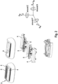
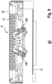
- the hair cutter 1 may be configured as an electric shaver and/or electric trimmer having one or more cutter units 3 which may be part of a cutter head 2 attached to a handle 10 of the hair cutter 1. More particularly, the hair cutter 1 may include an elongated handle 10 accommodating electronic and/or electric components such as a control unit, an electric drive motor 30 or a magnetic drive motor, and a drive train for transmitting the driving action of the motor to the cutter system 3 at the cutter head 2 which cutter head 2 may be positioned at one end of the elongated handle 10, cf. figure 1 .
- the cutter system 3 may include one or more shear foil cutters 4 for short stubbles and/or one or more comb-like cutter units 5 for longer stubbles or problem hair, wherein, for example, the cutter head 2 may have two elongated, comb-like long hair cutters 5 positioned between a pair of shear foil cutters 4, or, in the alternative, at outer edge portions of such a shear foil cutters.
- the cutter head 2 may include elongated cutter units with cooperating cutter elements which may reciprocate relative to each other along a linear path defining driving axis 20 so as to effect the cutting action by passing over each other.
- the cutter head 2 also may include rounded or circular cutter units with cooperating cutter elements rotating relative to each other to effect the cutting action which is basically similar to reciprocating cutting elements as radially extending teeth and/or a disk-like shear foil copperating with a disk-like blade element, when rotating and/or rotatorily oscillating, pass over each other, thereby effecting the cutting action.
- the drive system may include a motor 30 the shaft of which may rotate an eccentric drive pin which is received between the channel-like contours of a driver 18 of, for example an oscillating bridge which is connected to one or more of the cutting units 4 and 5 which is/are caused to reciprocate due to the engagement of the rotating eccentric drive pin with the contours of said driver 18.
- a motor 30 the shaft of which may rotate an eccentric drive pin which is received between the channel-like contours of a driver 18 of, for example an oscillating bridge which is connected to one or more of the cutting units 4 and 5 which is/are caused to reciprocate due to the engagement of the rotating eccentric drive pin with the contours of said driver 18.
- the cooperating cutting elements 11, 12 of the long hair cutters 5 basically may have - at least roughly - a plate-shaped configuration, wherein each cutting element may include one or more rows of cutting teeth.
- the cutting elements may be supported and positioned with their flat sides lying onto one another, so the cutting teeth of the cutting elements may touch each other back to back like the blades of a scissor.
- the cutter units 4 of the shear foil type may include a shear foil 12 provided with at least one field of cutting perforations and defining a skin contact surface of the cutter unit and a blade element having a plurality of cutting blades 11 moving under said shear foil to cooperate with the perforations thereof.
- the shear foil 12 may be a stationary cutter element, whereas the cutting blades may be drivable cutter elements driven via the aforementioned driver 18 by motor 30 to reciprocate along driving axis 20.
- the aforementioned long hair or comb-like cutter unit 5, more particularly the cutter elements 11 and 12 may be driven relative to each other along such driving axis 20.
- Such driving axis 20 may extend basically parallel to the skin contact surface 21 and substantially parallel to the longitudinal axis of the substantially elongated cutter units 4, 5 to allow for reciprocating of the elongated cutter elements 11, 12 relative to each other.
- Said cutter head 2 is attached to the handle 10, wherein the cutter head 2 may be slewably supported about a swiveling axis and about a tilting axis which swiveling and tilting axes may extend substantially perpendicular to each other and perpendicular to a longitudinal handle axis of the handle 10.
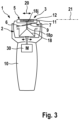
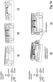
- each cutter unit 4, 5 are suspended movably relative to a cutter head frame 6 so as to allow for micro-diving and micro-tilting of the cutter head units 4 relative to the cutter head frame 6 and relative to each other. More particularly, each cutter unit 4, 5 may individually dive along a diving axis z which may extend substantially perpendicular to the skin contact surface 21, cf. figure 2 .
- each of the cutter units 4, 5 may individually tilt about a tilt axis y which extends substantially perpendicular to the aforementioned diving axis z and thus, substantially parallel to the skin contact surface 21 and at the same time, substantially perpendicular to a main axis of the corresponding cutter unit which main axis may be a longitudinal axis of the cutter unit when such cutter unit has an elongated shape, cf. figures 1 , 2 and 3 .
- the tilting axis y may extend perpendicular to such main axis 40 and substantially parallel to the skin contact surface 21.
- Such main axis 40 may extend in parallel to the longer side edges of the cutter head 2 and/or in parallel with a longitudinal axis of the elongated cutter elements 4, 5 and/or substantially perpendicular to the longitudinal handle axis of the handle 2.
- the cutter head 2 may have a - roughly speaking - substantially rectangular plate- or block-like shape with a pair of longer side edges arranged on opposite sides of the functional or skin-contact surface 13 which is facing away from handle 2.
- the dive axis z may extend substantially perpendicular to the skin contact surface 21.
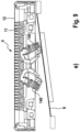
- an elastic support structure 7 including a spring mechanism 8 is provided to elastically support each of the cutter units 4, 5 at the cutter head frame 6.
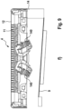
- the spring mechanism 8 of said support structure 7 includes a leaf spring 9 for each of the cutter units 4, 5.
- Such leaf spring may have an elongated, substantially bar-shaped or plate-like configuration, cf. for example figure 4 and figure 5 , wherein figure 4 shows a leaf spring 9 for elastically suspending a shear foil-type cutter unit 4 and figure 5 shows two leaf springs 9 for elastically suspending the long hair cutter units 5.
- a pair of leaf springs 9 may be connected to each other at one end thereof so both leaf springs 9 may have a common attachment point at the cutter head frame 6. Nevertheless, the leaf springs 9 may end and thus move individually to allow for individual self-adaption of the cutter unit supported thereby.
- each of the cutter units 4 and 5 may have its "own" leaf spring 9, wherein exactly one leaf spring 9 can be provided for each cutter unit 4, 5.
- said leaf spring 9 is rigidly attached, with one end portion 14, to a first end portion 4a, 5a or edge portion of said cutter unit 4, 5 and, with the other, opposite end portion 13, to said cutter head frame 6 at a spring support portion 17 thereof adjacent to a second end portion 4b, 5b or edge portion of the cutter unit 4, 5 opposite to the aforementioned first end portion 4a, 5a or edge portion thereof.
- the leaf spring 9 may extend, from its fixation point at the cutter head frame 6, across or along the cutter unit 4, 5 to hold said cutter unit 4, 5 at an end/edge portion at the opposite side away from the leaf spring fixation point at the cutter head 2. Due to the rigid attachment at both end portions, the leaf spring 9 stabilizes the cutter unit with regard to driving motions of the drivable cutter element 11 relative to this stationary cutter element 12, whereas at the same time self-adaption movements are allowed by means of bending the leaf spring 9.
- said leaf spring 9 may form a sort of double cantilever support structure for the cutter unit 4, 5, wherein the leaf spring 9 itself is cantilevered at the cutter head frame 6 and forms a cantilever, beam-like element projecting from the cutter head frame 6 and is fixedly attached thereto.
- the cutter unit 4, 5 is cantilevered at the opposite end portion of the leaf spring 9 and forms a sort of cantilevered element projecting from the leaf spring and fixedly attached thereto.
- the leaf spring 9 together with the cutter unit 4, 5 and the cutter head frame 6 attached to opposite ends 13, 14 of the leaf spring 9 may form a z-shaped support structure 7 allowing for diving and tilting of the cutter unit 4, 5 relative to the cutter head frame 6 along diving axis z and about tilt axis y due to elastic bending of the leaf spring 9, whereas said leaf spring may substantially rigidly hold the cutter unit in the direction of driving axis 20, i.e. perpendicular to the diving axis and to the tilt axis, thereby increasing driving efficiency.
- the support structure 7, and more particularly the spring mechanism 8 thereof, can be an asymmetric one, wherein only one leaf spring 9may be provided, as shown by the figures, so that only one end portion 4a, 5a or edge portion of the cutter unit 4, 5 is mounted to a leaf spring 9 and/or elastically held by a spring.
- the elastic support structure of the at least one cutter unit nevertheless may be configured to provide for a symmetric self-adaption, in particular symmetric micro diving and/or micro tilting.
- the leaf spring 9 may provide for the same tilt resistance and/or same dive resistance for both right and left cutter unit portions 4a and 4b, and 5a and 5b. More particularly, the leaf spring 9 may be configured such that the cutter unit 4, 5, despite the eccentric attachment of the leaf spring to the cutter unit, dives along a diving axis without tilting about a tilt axis when the cutter unit is subject to skin contact pressure represented by a resultant skin contact force going through the center of the cutter unit.
- the cutter unit when a skin contact force is supplied to the center of the skin contact surface of the cutter unit, the cutter unit does not tilt to the left side or to the right side, but dives translationally or uniformly at both ends, i.e. opposite end portions of the cutter unit dive the same distance, cf. Fig. 9b .
- the bending characteristic of the leaf spring 9 may be configured such that the response of the cutter unit 4, 5 to skin contact pressure in terms of micro diving and/or micro tilting movements is symmetric.
- the cutter unit 4, 5 dives translationally without tilting.
- the cutter unit may dive and tilt clockwise or only tilt clockwise.
- there may be diving and counter-clockwise tilting or only counter-clockwise tilting.
- the leaf spring 9 may have bending portions 9b adjacent to the end portions 13, 14 of the leaf spring which are attached to the cutter head 2 and the cutter unit 4, 5, respectively, wherein said bending portions 9b may provide for substantially identical bending stiffnesses and have substantially the same length. More particularly, such bending portions 9b may be arranged symmetrical and may provide for identical bending characteristics of the leaf spring 9 in the leaf spring region neighboring the cutter unit 4, 5and/or the cutter unit attachment point on the one hand and neighboring the cutter head 2 and/or cutter head attachment point on the other hand.
- the leaf spring 9 may include a center portion 9c connecting said bending portions 9b and configured to have a more rigid characteristic than the bending portions 9b.
- said center portion 9c of the leaf spring 9 may have a center thickness 9ct larger than the thicknesses of the bending portions 9b.
- the center portion may have a center width 9cw which is larger than the width of the bending portions of the leaf spring, cf. Fig. 4 .
- the center portion 9c is significantly more rigid and/or stiffer than the bending portions s9b o bending of the leaf spring 9 due to skin contact pressure of the cutter unit occurs at well-defined portions and/or positions so micro diving and/or micro tilting of the cutter unit 4, 5 due to bending of the leaf spring 9 is well-controlled.
- one or more reinforcement ribs may be provided at such center portion 9c to increase thickness and/or width of said center portion.
- the leaf spring 9 may be inclined relative to the skin contact surface 21 of the cutter unit 4, 5 and/or to the driving axis 20 along which the cutter elements reciprocate or move relative to each other, at a relatively small angle ⁇ of inclination which, in some diving/tilting position, and/or in a starting or home position, even may become zero.
- the leaf spring 9, with its longitudinal axis, and/or a virtual connection line going through the end portions 13, 14 of the leaf spring 9 may extend parallel to or at an acute angle to a virtual plane perpendicular to the diving axis and/or parallel to the skin contact surface 21 of the cutter head 2, wherein such acute angle ⁇ may be less than 30° or less than 20° or less than 10°, when the cutter unit 4, 5 is in its sort of resting position when no skin contact pressure is applied to the cutter unit.
- the leaf spring may be inclined to said virtual plane at a positive acute angle or at a negative acute angle ⁇ .
- figure 9e shows that the connection point of the leaf spring 9 to the cutter unit 4, 5 may be positioned higher than the connection point of the leaf spring 9 to the cutter head frame, when height is considered the direction perpendicular to the skin contact surface 21.
- the leaf spring's connection point to the cutter unit 4, 5 may be positioned lower than the leaf spring's connection point to the cutter head frame, in the alternative to figure 9e , when the cutter unit is in its home position not yet subject to skin contact pressure.
- leaf spring 9 may extend substantially parallel to the skin contact surface 21 when the cutter unit is in its neutral position subject to zero skin contact pressure.
- the leaf spring's connection points to the cutter unit 4, 5 on the one hand and to the cutter head frame on the other hand may be arranged at substantially the same height, cf. figure 9g .
- the leaf spring 9 may have a substantially straight longitudinal axis, cf. Fig. 4 and 5 , so as to have a stiff and rigid configuration of the leaf spring 9 with regard to driving movements, wherein such straight longitudinal axis may extend almost parallel to or only slightly inclined relative to the driving axis 20 so the leaf spring 9 shows significant resistance against reaction forces implied by the driving movements of the cutter elements.
- the driving axis of the cutter elements may extend substantially parallel to the skin contact surface 21, in particular when the cutter elements have an elongated configuration, wherein the cutter elements may reciprocate relative to each other along such driving axis.
- the leaf spring 9 may be arranged in a common plane containing the driving axis and the longitudinal leaf spring axis, cf. Fig. 6 and 7 . More particularly, although the longitudinal axis of the leaf spring may extend in such virtual plane, the leaf spring, with its width direction, may be arranged substantially perpendicular to the virtual plane so that movements of the leaf spring due to bending thereof occur substantially parallel to such virtual plane.
- the leaf spring 9 does not have to provide for biasing pressure or biasing forces urging the reciprocating cutting elements 11, 12 onto each other, but separate biasing means such as one or more springs 140 such as screw springs may be provided for pressing the cooperating stationary and drivable cutter elements 11, 12 onto each other.
- one or more springs 140 such as screw springs may be active between the drivable cutter element 11 and the stationary cutter element 12 to urge them towards each other.
- said springs 40 may be supported at a shear foil carrier or a stationary cutter support frame on the one hand and apply a spring force onto the drivable cutter element 11 so as to urge the drivable cutter element 11 onto the stationary cutter element 12.
- the aforementioned leaf spring 9 of the spring mechanism 8 of the support structure 7 may exclusively serve the function to adjust the resistance and/or restoring and/or elasticity of the cutter units 4, 5 with regard to the micro-diving and micro-tilting or more generally, the desired self-adaption movements.
- the driving resistance in terms of friction of the movable and stationary cutter elements relative to each other may be independent of the leaf spring, wherein such driving resistance in terms of friction may depend on the contact pressure between the movable and stationary cutter elements which may be controlled by the one or more springs 140 shown by figures 5 , 7 and 9 .
- the drive pin 18p of transmitter 18, cf. figure 3 does not have to be elastically urged towards the drivable cutter element 11, but may be received in a transmission joint 18j of the drivable cutter unit 11 in an axially loose way.
- the transmission joint 18j may be configured to only transmit forces and/or torque along or about the driving axis 20, whereas no forces or torques are transmitted in directions perpendicular thereto. In particular, no forces need to be transmitted in the longitudinal direction of the drive pin 18p of drive bridge 18.
- the drive joint 18j still may be configured to transmit biasing forces urging the drivable cutter unit 11 against the stationary cutter element 12.
- the transmitter joint 18p may include a cone-shaped drive pin and a cone-shaped recess receiving the drive pin, or a spherical drive pin received in a spherical recess, wherein such drive pin may be urged in a direction perpendicular to the skin contact surface 21 to press the drivable cutter element 11 towards the stationary cutter element 12.
- the leaf spring 9 may be configured to apply a biasing force onto the stationary cutter element 12 going into the opposite direction, for example the leaf spring 9 may urge the stationary cutter element 12 towards the handle 10 to balance the drive pin biasing to some extent.
- a light-footed self-adaption with very little skin contact pressure may be achieved.
- diving resistance may be controlled exclusively by the leaf spring 9, in particular when there is no biasing of the aforementioned drive joint.
- additional spring 150 for controlling diving may be configured to be inactive in the cutter unit's neutral or home position when there is no skin contact pressure, and/or inactive over a first portion of the diving path out of said neutral or home position.
- the additional spring 150 may be inactive as long as the cutter unit 4, 5 has not yet covered a certain diving distance.
- FIG. 9h there may be some play or distance between spring 150 and cutter unit 4, 5 when the cutter unit is in its neutral or home position. More particularly, such play or distance 160 may be provided between a contact element 161 which is provided at one end of the spring 150 and is configured to contact the cutter unit 4, 5.
- Such contact element 161 may have a spherical shape or at least a partly spherical contact surface to avoid influence of the spring 150 on to tilting movements and/or to allow control of tilting movements exclusively by the leaf spring 9.
- the aforementioned contact element 161 and its counterpart 162 at the cutter unit 4, 5 may be configured to transmit forces in a direction substantially perpendicular to the skin contact surface, but no torques and no forces trying to tilt or pivot the cutter unit 4, 5.
- the additional spring 150 may become active for a second or last portion of the diving path.
- the contact element 161 gets into engagement with the cutter unit 4, 5, in particular the cone-shaped engagement element 162 so the cutter unit needs to deflect not only the leaf spring 9, but also the additional spring 150 to further dive.
- the restoring characteristic of the spring mechanism 8 with regard to the diving adjustments may have a two-step configuration.
- a linear restoring characteristic may be provided by the leaf spring 9 only, whereas for a final portion of the diving path a linear, but stronger restoring characteristic may be provided by the leaf spring 9 together with the additional spring 150.
- the leaf spring 9 may be configured to allow for light-footed self-adaption in terms of micro-tilting and micro-diving with very little skin contact pressure.
- the entire cutter head 2 may move relative to the handle 2.
Landscapes
- Life Sciences & Earth Sciences (AREA)
- Forests & Forestry (AREA)
- Engineering & Computer Science (AREA)
- Mechanical Engineering (AREA)
- Dry Shavers And Clippers (AREA)
Priority Applications (9)
| Application Number | Priority Date | Filing Date | Title |
|---|---|---|---|
| EP23182300.6A EP4484084A1 (de) | 2023-06-29 | 2023-06-29 | Haarschneidegerät |
| US18/756,480 US20250001628A1 (en) | 2023-06-29 | 2024-06-27 | Hair cutter |
| PCT/IB2024/056254 WO2025003940A1 (en) | 2023-06-29 | 2024-06-27 | Hair cutter |
| EP24184985.0A EP4484086A1 (de) | 2023-06-29 | 2024-06-27 | Haarschneidegerät |
| US18/756,377 US20250001626A1 (en) | 2023-06-29 | 2024-06-27 | Hair cutter |
| PCT/IB2024/056253 WO2025003939A1 (en) | 2023-06-29 | 2024-06-27 | Hair cutter |
| PCT/IB2024/056252 WO2025003938A1 (en) | 2023-06-29 | 2024-06-27 | Hair cutter |
| EP24184984.3A EP4484085A1 (de) | 2023-06-29 | 2024-06-27 | Haarschneidegerät |
| US18/756,440 US20250001627A1 (en) | 2023-06-29 | 2024-06-27 | Hair cutter |
Applications Claiming Priority (1)
| Application Number | Priority Date | Filing Date | Title |
|---|---|---|---|
| EP23182300.6A EP4484084A1 (de) | 2023-06-29 | 2023-06-29 | Haarschneidegerät |
Publications (1)
| Publication Number | Publication Date |
|---|---|
| EP4484084A1 true EP4484084A1 (de) | 2025-01-01 |
Family
ID=87060657
Family Applications (3)
| Application Number | Title | Priority Date | Filing Date |
|---|---|---|---|
| EP23182300.6A Pending EP4484084A1 (de) | 2023-06-29 | 2023-06-29 | Haarschneidegerät |
| EP24184985.0A Pending EP4484086A1 (de) | 2023-06-29 | 2024-06-27 | Haarschneidegerät |
| EP24184984.3A Pending EP4484085A1 (de) | 2023-06-29 | 2024-06-27 | Haarschneidegerät |
Family Applications After (2)
| Application Number | Title | Priority Date | Filing Date |
|---|---|---|---|
| EP24184985.0A Pending EP4484086A1 (de) | 2023-06-29 | 2024-06-27 | Haarschneidegerät |
| EP24184984.3A Pending EP4484085A1 (de) | 2023-06-29 | 2024-06-27 | Haarschneidegerät |
Country Status (3)
| Country | Link |
|---|---|
| US (3) | US20250001627A1 (de) |
| EP (3) | EP4484084A1 (de) |
| WO (3) | WO2025003938A1 (de) |
Citations (4)
| Publication number | Priority date | Publication date | Assignee | Title |
|---|---|---|---|---|
| US3950847A (en) | 1973-07-10 | 1976-04-20 | U.S. Philips Corporation | Dry shaver |
| US5185926A (en) * | 1992-02-07 | 1993-02-16 | Remington Products, Inc. | Multiple foil and cutting blade assembly for electric dry shavers |
| DE102008031135A1 (de) * | 2008-07-01 | 2010-01-07 | Braun Gmbh | Schneideinrichtung zum Entfernen von Haaren sowie Federelement hierzu |
| US20230031671A1 (en) * | 2021-07-29 | 2023-02-02 | Braun Gmbh | Personal care device |
Family Cites Families (2)
| Publication number | Priority date | Publication date | Assignee | Title |
|---|---|---|---|---|
| DE10330978A1 (de) | 2003-07-09 | 2005-02-10 | Braun Gmbh | Elektrisches Kleingerät mit einem Elektromotor zur Erzeugung einer oszillierenden Bewegung |
| EP3396826B1 (de) * | 2017-04-27 | 2022-10-19 | Braun GmbH | Elektrogerät zur körperpflege |
-
2023
- 2023-06-29 EP EP23182300.6A patent/EP4484084A1/de active Pending
-
2024
- 2024-06-27 WO PCT/IB2024/056252 patent/WO2025003938A1/en active Pending
- 2024-06-27 WO PCT/IB2024/056253 patent/WO2025003939A1/en active Pending
- 2024-06-27 EP EP24184985.0A patent/EP4484086A1/de active Pending
- 2024-06-27 WO PCT/IB2024/056254 patent/WO2025003940A1/en active Pending
- 2024-06-27 US US18/756,440 patent/US20250001627A1/en active Pending
- 2024-06-27 EP EP24184984.3A patent/EP4484085A1/de active Pending
- 2024-06-27 US US18/756,377 patent/US20250001626A1/en active Pending
- 2024-06-27 US US18/756,480 patent/US20250001628A1/en active Pending
Patent Citations (4)
| Publication number | Priority date | Publication date | Assignee | Title |
|---|---|---|---|---|
| US3950847A (en) | 1973-07-10 | 1976-04-20 | U.S. Philips Corporation | Dry shaver |
| US5185926A (en) * | 1992-02-07 | 1993-02-16 | Remington Products, Inc. | Multiple foil and cutting blade assembly for electric dry shavers |
| DE102008031135A1 (de) * | 2008-07-01 | 2010-01-07 | Braun Gmbh | Schneideinrichtung zum Entfernen von Haaren sowie Federelement hierzu |
| US20230031671A1 (en) * | 2021-07-29 | 2023-02-02 | Braun Gmbh | Personal care device |
Also Published As
| Publication number | Publication date |
|---|---|
| EP4484086A1 (de) | 2025-01-01 |
| WO2025003939A1 (en) | 2025-01-02 |
| US20250001626A1 (en) | 2025-01-02 |
| US20250001628A1 (en) | 2025-01-02 |
| EP4484085A1 (de) | 2025-01-01 |
| WO2025003938A1 (en) | 2025-01-02 |
| WO2025003940A1 (en) | 2025-01-02 |
| US20250001627A1 (en) | 2025-01-02 |
Similar Documents
| Publication | Publication Date | Title |
|---|---|---|
| EP3907046B1 (de) | Elektrischer bartschneider | |
| EP3907043B1 (de) | Elektrischer bartschneider | |
| JP5643653B2 (ja) | 枢動可能に配置された切断素子のアセンブリを有するシェービング装置 | |
| EP3907049B1 (de) | Elektrischer bartschneider | |
| CN110303527B (zh) | 毛发移除装置 | |
| CN100551646C (zh) | 具有位于外壳和剃须头之间的铰链的剃须刀 | |
| EP3907048B1 (de) | Elektrischer bartschneider | |
| KR20010024283A (ko) | 건식 전기 면도기 | |
| EP4484084A1 (de) | Haarschneidegerät | |
| JP6892468B2 (ja) | 電気的駆動装置 | |
| CN115551685B (en) | Electric beard trimmer | |
| JP3210722B2 (ja) | 往復式電気かみそり |
Legal Events
| Date | Code | Title | Description |
|---|---|---|---|
| PUAI | Public reference made under article 153(3) epc to a published international application that has entered the european phase |
Free format text: ORIGINAL CODE: 0009012 |
|
| STAA | Information on the status of an ep patent application or granted ep patent |
Free format text: STATUS: THE APPLICATION HAS BEEN PUBLISHED |
|
| AK | Designated contracting states |
Kind code of ref document: A1 Designated state(s): AL AT BE BG CH CY CZ DE DK EE ES FI FR GB GR HR HU IE IS IT LI LT LU LV MC ME MK MT NL NO PL PT RO RS SE SI SK SM TR |
|
| STAA | Information on the status of an ep patent application or granted ep patent |
Free format text: STATUS: REQUEST FOR EXAMINATION WAS MADE |
|
| 17P | Request for examination filed |
Effective date: 20250625 |
|
| GRAP | Despatch of communication of intention to grant a patent |
Free format text: ORIGINAL CODE: EPIDOSNIGR1 |
|
| STAA | Information on the status of an ep patent application or granted ep patent |
Free format text: STATUS: GRANT OF PATENT IS INTENDED |
|
| INTG | Intention to grant announced |
Effective date: 20250923 |