EP4484047A1 - Electric resistance welded pipe and method for manufacturing same - Google Patents
Electric resistance welded pipe and method for manufacturing same Download PDFInfo
- Publication number
- EP4484047A1 EP4484047A1 EP22933652.4A EP22933652A EP4484047A1 EP 4484047 A1 EP4484047 A1 EP 4484047A1 EP 22933652 A EP22933652 A EP 22933652A EP 4484047 A1 EP4484047 A1 EP 4484047A1
- Authority
- EP
- European Patent Office
- Prior art keywords
- tube
- pipe
- electric resistance
- less
- resistance welded
- Prior art date
- Legal status (The legal status is an assumption and is not a legal conclusion. Google has not performed a legal analysis and makes no representation as to the accuracy of the status listed.)
- Pending
Links
Images



Classifications
-
- B—PERFORMING OPERATIONS; TRANSPORTING
- B23—MACHINE TOOLS; METAL-WORKING NOT OTHERWISE PROVIDED FOR
- B23K—SOLDERING OR UNSOLDERING; WELDING; CLADDING OR PLATING BY SOLDERING OR WELDING; CUTTING BY APPLYING HEAT LOCALLY, e.g. FLAME CUTTING; WORKING BY LASER BEAM
- B23K11/00—Resistance welding; Severing by resistance heating
- B23K11/08—Seam welding not restricted to one of the preceding subgroups
- B23K11/087—Seam welding not restricted to one of the preceding subgroups for rectilinear seams
- B23K11/0873—Seam welding not restricted to one of the preceding subgroups for rectilinear seams of the longitudinal seam of tubes
-
- B—PERFORMING OPERATIONS; TRANSPORTING
- B21—MECHANICAL METAL-WORKING WITHOUT ESSENTIALLY REMOVING MATERIAL; PUNCHING METAL
- B21C—MANUFACTURE OF METAL SHEETS, WIRE, RODS, TUBES, PROFILES OR LIKE SEMI-MANUFACTURED PRODUCTS OTHERWISE THAN BY ROLLING; AUXILIARY OPERATIONS USED IN CONNECTION WITH METAL-WORKING WITHOUT ESSENTIALLY REMOVING MATERIAL
- B21C37/00—Manufacture of metal sheets, rods, wire, tubes, profiles or like semi-manufactured products, not otherwise provided for; Manufacture of tubes of special shape
- B21C37/06—Manufacture of metal sheets, rods, wire, tubes, profiles or like semi-manufactured products, not otherwise provided for; Manufacture of tubes of special shape of tubes or metal hoses; Combined procedures for making tubes, e.g. for making multi-wall tubes
- B21C37/08—Making tubes with welded or soldered seams
-
- B—PERFORMING OPERATIONS; TRANSPORTING
- B23—MACHINE TOOLS; METAL-WORKING NOT OTHERWISE PROVIDED FOR
- B23K—SOLDERING OR UNSOLDERING; WELDING; CLADDING OR PLATING BY SOLDERING OR WELDING; CUTTING BY APPLYING HEAT LOCALLY, e.g. FLAME CUTTING; WORKING BY LASER BEAM
- B23K13/00—Welding by high-frequency current heating
-
- B—PERFORMING OPERATIONS; TRANSPORTING
- B23—MACHINE TOOLS; METAL-WORKING NOT OTHERWISE PROVIDED FOR
- B23K—SOLDERING OR UNSOLDERING; WELDING; CLADDING OR PLATING BY SOLDERING OR WELDING; CUTTING BY APPLYING HEAT LOCALLY, e.g. FLAME CUTTING; WORKING BY LASER BEAM
- B23K13/00—Welding by high-frequency current heating
- B23K13/01—Welding by high-frequency current heating by induction heating
-
- B—PERFORMING OPERATIONS; TRANSPORTING
- B23—MACHINE TOOLS; METAL-WORKING NOT OTHERWISE PROVIDED FOR
- B23K—SOLDERING OR UNSOLDERING; WELDING; CLADDING OR PLATING BY SOLDERING OR WELDING; CUTTING BY APPLYING HEAT LOCALLY, e.g. FLAME CUTTING; WORKING BY LASER BEAM
- B23K13/00—Welding by high-frequency current heating
- B23K13/01—Welding by high-frequency current heating by induction heating
- B23K13/02—Seam welding
- B23K13/025—Seam welding for tubes
-
- B—PERFORMING OPERATIONS; TRANSPORTING
- B23—MACHINE TOOLS; METAL-WORKING NOT OTHERWISE PROVIDED FOR
- B23K—SOLDERING OR UNSOLDERING; WELDING; CLADDING OR PLATING BY SOLDERING OR WELDING; CUTTING BY APPLYING HEAT LOCALLY, e.g. FLAME CUTTING; WORKING BY LASER BEAM
- B23K31/00—Processes relevant to this subclass, specially adapted for particular articles or purposes, but not covered by any single one of main groups B23K1/00 - B23K28/00
- B23K31/02—Processes relevant to this subclass, specially adapted for particular articles or purposes, but not covered by any single one of main groups B23K1/00 - B23K28/00 relating to soldering or welding
- B23K31/027—Making tubes by soldering or welding
-
- B—PERFORMING OPERATIONS; TRANSPORTING
- B23—MACHINE TOOLS; METAL-WORKING NOT OTHERWISE PROVIDED FOR
- B23K—SOLDERING OR UNSOLDERING; WELDING; CLADDING OR PLATING BY SOLDERING OR WELDING; CUTTING BY APPLYING HEAT LOCALLY, e.g. FLAME CUTTING; WORKING BY LASER BEAM
- B23K31/00—Processes relevant to this subclass, specially adapted for particular articles or purposes, but not covered by any single one of main groups B23K1/00 - B23K28/00
- B23K31/10—Processes relevant to this subclass, specially adapted for particular articles or purposes, but not covered by any single one of main groups B23K1/00 - B23K28/00 relating to cutting or desurfacing
-
- B—PERFORMING OPERATIONS; TRANSPORTING
- B23—MACHINE TOOLS; METAL-WORKING NOT OTHERWISE PROVIDED FOR
- B23K—SOLDERING OR UNSOLDERING; WELDING; CLADDING OR PLATING BY SOLDERING OR WELDING; CUTTING BY APPLYING HEAT LOCALLY, e.g. FLAME CUTTING; WORKING BY LASER BEAM
- B23K33/00—Specially-profiled edge portions of workpieces for making soldering or welding connections; Filling the seams formed thereby
- B23K33/004—Filling of continuous seams
- B23K33/006—Filling of continuous seams for cylindrical workpieces
-
- C—CHEMISTRY; METALLURGY
- C22—METALLURGY; FERROUS OR NON-FERROUS ALLOYS; TREATMENT OF ALLOYS OR NON-FERROUS METALS
- C22C—ALLOYS
- C22C38/00—Ferrous alloys, e.g. steel alloys
- C22C38/002—Ferrous alloys, e.g. steel alloys containing In, Mg, or other elements not provided for in one single group C22C38/001 - C22C38/60
-
- C—CHEMISTRY; METALLURGY
- C22—METALLURGY; FERROUS OR NON-FERROUS ALLOYS; TREATMENT OF ALLOYS OR NON-FERROUS METALS
- C22C—ALLOYS
- C22C38/00—Ferrous alloys, e.g. steel alloys
- C22C38/02—Ferrous alloys, e.g. steel alloys containing silicon
-
- C—CHEMISTRY; METALLURGY
- C22—METALLURGY; FERROUS OR NON-FERROUS ALLOYS; TREATMENT OF ALLOYS OR NON-FERROUS METALS
- C22C—ALLOYS
- C22C38/00—Ferrous alloys, e.g. steel alloys
- C22C38/04—Ferrous alloys, e.g. steel alloys containing manganese
-
- C—CHEMISTRY; METALLURGY
- C22—METALLURGY; FERROUS OR NON-FERROUS ALLOYS; TREATMENT OF ALLOYS OR NON-FERROUS METALS
- C22C—ALLOYS
- C22C38/00—Ferrous alloys, e.g. steel alloys
- C22C38/08—Ferrous alloys, e.g. steel alloys containing nickel
-
- C—CHEMISTRY; METALLURGY
- C22—METALLURGY; FERROUS OR NON-FERROUS ALLOYS; TREATMENT OF ALLOYS OR NON-FERROUS METALS
- C22C—ALLOYS
- C22C38/00—Ferrous alloys, e.g. steel alloys
- C22C38/12—Ferrous alloys, e.g. steel alloys containing tungsten, tantalum, molybdenum, vanadium, or niobium
-
- C—CHEMISTRY; METALLURGY
- C22—METALLURGY; FERROUS OR NON-FERROUS ALLOYS; TREATMENT OF ALLOYS OR NON-FERROUS METALS
- C22C—ALLOYS
- C22C38/00—Ferrous alloys, e.g. steel alloys
- C22C38/14—Ferrous alloys, e.g. steel alloys containing titanium or zirconium
-
- C—CHEMISTRY; METALLURGY
- C22—METALLURGY; FERROUS OR NON-FERROUS ALLOYS; TREATMENT OF ALLOYS OR NON-FERROUS METALS
- C22C—ALLOYS
- C22C38/00—Ferrous alloys, e.g. steel alloys
- C22C38/16—Ferrous alloys, e.g. steel alloys containing copper
-
- C—CHEMISTRY; METALLURGY
- C22—METALLURGY; FERROUS OR NON-FERROUS ALLOYS; TREATMENT OF ALLOYS OR NON-FERROUS METALS
- C22C—ALLOYS
- C22C38/00—Ferrous alloys, e.g. steel alloys
- C22C38/18—Ferrous alloys, e.g. steel alloys containing chromium
-
- B—PERFORMING OPERATIONS; TRANSPORTING
- B23—MACHINE TOOLS; METAL-WORKING NOT OTHERWISE PROVIDED FOR
- B23K—SOLDERING OR UNSOLDERING; WELDING; CLADDING OR PLATING BY SOLDERING OR WELDING; CUTTING BY APPLYING HEAT LOCALLY, e.g. FLAME CUTTING; WORKING BY LASER BEAM
- B23K2101/00—Articles made by soldering, welding or cutting
- B23K2101/04—Tubular or hollow articles
- B23K2101/06—Tubes
-
- B—PERFORMING OPERATIONS; TRANSPORTING
- B23—MACHINE TOOLS; METAL-WORKING NOT OTHERWISE PROVIDED FOR
- B23K—SOLDERING OR UNSOLDERING; WELDING; CLADDING OR PLATING BY SOLDERING OR WELDING; CUTTING BY APPLYING HEAT LOCALLY, e.g. FLAME CUTTING; WORKING BY LASER BEAM
- B23K2103/00—Materials to be soldered, welded or cut
- B23K2103/02—Iron or ferrous alloys
- B23K2103/04—Steel or steel alloys
Definitions
- the present disclosure relates to an electric resistance welded pipe or tube and a method of producing the same.
- the present disclosure especially relates to an electric resistance welded pipe or tube suitable for use as an outer pipe or tube of a double (i.e. double-walled) pipe or tube formed by layering different metal materials on the inside and outside, and a method of producing the same.
- Metal pipes or tubes are usually single (i.e. single-walled) pipes or tubes made up of one type of metal material. Depending on the application, however, double pipes or tubes made up of two different types of metal materials may be used to provide functionality to the inner or outer surface of the metal pipe or tube.
- a double pipe or tube is often used in which a high corrosion resistant alloy such as a Ni-based alloy is used for the inner pipe or tube and a low-carbon low-alloy steel pipe or tube is used for the open pipe or tube, which is a cylindrical strip before welding, of the outer pipe or tube.
- a high corrosion resistant alloy such as a Ni-based alloy
- a low-carbon low-alloy steel pipe or tube is used for the open pipe or tube, which is a cylindrical strip before welding, of the outer pipe or tube.
- JP S58-41611 A proposes a method in which cold drawing is performed using a tapered die, an inner pipe or tube is inserted inside an outer pipe or tube, then diameter reduction is performed so that the gap between the outer and inner pipes or tubes will be 0.02 mm or less, and further diameter expansion is performed using an inside expansion plug to expand the inner diameter of the inner pipe or tube and fit the outer and inner pipes or tubes together.
- the cutting residual part convexly raised in the wall thickness direction after cutting the weld bead on the inner side is the weld metal part and the heat-affected zone (which are also collectively referred to as "weld portion" in the present disclosure) around the joint deformed by high temperature in the wall thickness direction by pressing (upset) by the squeeze rolls of the welding stand.
- FIG. 1 is a schematic diagram illustrating an example of a welding process in production of electric resistance welded pipes or tubes.
- a steel strip 1 as material is straightened on the entry side by a leveler 2 for example, then subjected to intermediate forming into an open pipe or tube by a cage roll group 3 composed of a plurality of rolls, and then subjected to finish forming into a pipe or tube shape by a fin pass roll group 4 composed of a plurality of rolls.
- electric resistance welding is performed on the widthwise end surfaces of the steel strip 1 (i.e. the circumferential end surfaces of the open pipe or tube) using a welder 6 while pressing with squeeze rolls 5, to yield an electric resistance welded pipe or tube 7.
- An example of the steel strip 1 is a hot-rolled steel sheet of carbon steel.
- induction heating whereby, while passing the steel strip 1 which has been finished into a pipe or tube shape through a work coil provided with an impeder, the widthwise ends of the steel strip 1 are heated; and direct current heating whereby a contact tip is brought into direct contact with the widthwise ends of the steel strip 1 to heat the widthwise ends of the steel strip 1.
- the high-frequency current used during electric resistance welding is mainly 400 kHz or less.
- the frequency is selected for each welder depending on the application of the product pipe or tube.
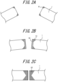
- FIGS. 2A to 2C illustrate a process of heating the widthwise end surfaces of the steel strip 1 (the circumferential end surfaces of the open pipe or tube, hereafter also simply referred to as "end surfaces") in electric resistance welding in conventional technology.
- skin effect heat is concentrated at the corners of each end surface (see FIG. 2A ).
- proximity effect heat is concentrated at the corners of each end surface (see FIG. 2B ).
- a heating phenomenon specific to high-frequency heating occurs in which proximity effect is exerted on the entire end surface (heat-affected zone 63 immediately before electric resistance welding) (see FIG. 2C ).
- heat generation through high-frequency heating is caused by hysteresis loss and eddy current loss in the heated object.
- eddy current which causes eddy current loss flows concentratedly on the surface of the heated object when the frequency of the current increases.
- the depth from the surface of the heated object to which heating due to eddy current loss reaches is called the penetration depth.
- the penetration depth is inversely proportional to the square root of the frequency of the current.
- the high-temperature deformation of the heat-affected zones of the ends can be localized in the upset of the squeeze rolls 5 (see FIG. 1 ) downstream of the heating process, with it being possible to make the weld bead smaller.
- locally concentrating the high-temperature deformation of the heat-affected zones of the ends increases the pressure of the upset and promotes the discharge of molten metal containing oxides, so that the quality of the weld portion is improved.
- FIGS. 3A to 3C schematically illustrate an example of the heating state of the end surfaces 10 (ends) of the steel strip 1 before electric resistance welding in the present disclosure.
- direction R1 is the radially outward direction of the open pipe or tube to be worked into an electric resistance welded pipe or tube
- direction R2 is the radially inward direction of the open pipe or tube.
- the heat generated at the corners due to skin effect in the initial stage of the heating process (see FIGS. 3A to 3C ) is dispersed to the surroundings of the corners of each end surface 10.
- the heat generated at the corners is dispersed over a wider range.
- This action expands the heat generation range (heated part 61 due to skin effect) to the wall thickness center part (i.e. the center of the root face 52) of the end surface 10 of the steel strip 1, and reduces the temperature difference between the faces 50 which are the inner and outer surfaces (the inward facing surface and the outward facing surface) of the end surface 10 and the wall thickness center part (the center of the root face 52). Subsequently, when proximity effect occurs (see FIG. 3B ), the end surface 10 has an approximately uniform temperature distribution.
- the groove shape is a double V groove in which the width of the root face 52 in the wall thickness direction of the steel strip 1 is 50 % or more and 80 % or less of the average wall thickness of the steel strip 1.
- the width of the root face 52 in the wall thickness direction of the steel strip 1 is hereafter simply referred to as the "width of the root face 52".
- the wall thickness direction of the steel strip 1 and the thickness direction of the pipe or tube wall of the electric resistance welded pipe or tube formed from the steel strip 1 are hereafter collectively referred to as "wall thickness direction”.
- the width of the root face 52 is less than 50 % of the average wall thickness, the volume of the end of the steel strip 1 that melts during electric resistance welding is excessively small, so that molten metal sufficient to discharge oxides to the outside by upset cannot be obtained. If the width of the root face 52 is more than 80 % of the average wall thickness, the distance of heat transfer from the heated part 61 due to skin effect at the corners on the faces 50, which are the inner and outer surfaces of the end surface 10 with the groove shape, to the wall thickness center part is long, making it impossible to sufficiently heat the wall thickness center part through heat transfer from the heated part 61 due to skin effect.
- the width of the root face 52 of the groove shape is preferably 60 % or more.
- the width of the root face 52 of the groove shape is preferably 70 % or less.
- the average wall thickness of the electric resistance welded pipe or tube refers to the average value of the pipe or tube wall thickness at three points of ⁇ 90° and 180° in the circumferential direction of the electric resistance welded pipe or tube (hereafter simply referred to as "circumferential direction") from the circumferential center of the weld portion 60 (see FIG. 4 ) of the electric resistance welded pipe or tube after welding.
- the bevel angle of each of the faces 50 which are the inner and outer surfaces of the groove machined onto the end surface 10 and the pipe or tube inner and outer surfaces connected to the end surface 10, is 10° or more and 30° or less.
- the edges of the joint surface (end surface 10) on the pipe or tube inner and outer surfaces (inner and outer sides) are almost at right angles, i.e. almost rectangular, so that the heat generated due to skin effect is concentrated at the edges. This causes a significant temperature difference between the pipe or tube inner and outer sides and the wall thickness center part of the end surface 10, degrading the quality of the weld portion 60 (see FIG. 4 ).
- the bevel angle of the groove is more than 30°, even when the minimum width of the root face 52 is secured, the part reduced in thickness by groove machining remains after welding, and consequently the desired shape of the weld portion 60 cannot be obtained.
- the bevel angle is preferably 15° or more.
- the bevel angle is preferably 25° or less.
- the shape of the double V groove (end surface 10) does not need to be symmetrical on the inner and outer sides of the pipe or tube, as long as the groove shape satisfies the foregoing width of the root face 52 and bevel angle on both the inner and outer sides.
- the groove (end surface 10) may be worked by any method, such as a method of mechanically grinding either the steel strip before being made into an open pipe or tube or the open pipe or tube before welding or a method of forming the groove with a tapered roll.
- the amount of upset by the squeeze rolls 5 is preferably 20 % or more and 60 % or less of the sheet thickness (nominal thickness) of the steel strip 1.
- the amount of upset is controlled based on the outer circumferential length of the pipe or tube.
- This process has the effect of discharging molten metal containing oxides generated on both widthwise end surfaces of the open pipe or tube during the heating process to the outside of the pipe or tube. If the amount of upset is less than 20 % of the average wall thickness, the discharge of the weld metal may be insufficient, causing degradation in the quality of the weld portion 60 (see FIG. 4 ). If the amount of upset is more than 60 % of the average wall thickness, the metal flow including the segregation zone near the weld portion is excessively steep and is exposed to the outside. Such steep segregation zone serves as a crack initiation point, making the weld portion 60 susceptible to cracking.
- the amount of upset is more preferably 25 % or more of the sheet thickness.
- the amount of upset is more preferably 55 % or less of the sheet thickness.
- the amount of upset is further preferably 35 % or more of the sheet thickness.
- the amount of upset is further preferably 50 % or less of the sheet thickness.
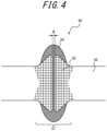
- the cross section of the weld portion 60 formed in the longitudinal direction of the electric resistance welded pipe or tube by electric resistance welding has a weld metal part 64, a heat-affected zone 65, and a base metal part 66 in this order from the circumferential center of the weld portion 60.
- weld metal means the metal that has melted during welding and subsequently solidified, in the electric resistance welded pipe or tube.
- the steel strip 1 is carbon steel or low-alloy steel, when morphology is made visible by natal etching, the weld metal can be identified as a region observed as white by an optical microscope.
- the part of the weld portion 60 raised on the inner and outer sides, including the weld metal part 64 and the heat-affected zone 65, is called a weld bead 67.
- the width of the weld metal part 64 in the circumferential direction is 1 ⁇ m or more and 800 ⁇ m or less over the entire thickness of the electric resistance welded pipe or tube (i.e. over the entire area in the wall thickness direction). If the width of the weld metal part 64 is less than 1 ⁇ m, there is not sufficient weld metal to join both end surfaces of the open pipe or tube, causing the weld portion 60 to crack. If the width of the weld metal part 64 is more than 800 ⁇ m, the quality of the weld portion 60 degrades due to insufficient discharge of molten metal by upset.
- the width of the weld metal part 64 is preferably 1.5 ⁇ m or more.
- the width of the weld metal part 64 is preferably 500 ⁇ m or less.
- the width of the weld metal part 64 over the entire thickness of the electric resistance welded pipe or tube tends to be larger on the inner and outer sides and smaller in the vicinity of the wall thickness center. This indicates that the molten state of both circumferential end surfaces of the open pipe or tube immediately before the squeeze rolls (see FIG. 1 ) is non-uniform in the wall thickness direction. If the distribution is noticeably non-uniform, when discharging the weld metal part 64 to the outside by upset, the flow of the weld metal is hindered by unmelted sites. This degrades the quality of the weld portion 60.
- the frequency of high-frequency current used in the welder 6 is 500 kHz or more and 5000 kHz or less in the present disclosure.
- the frequency increases, the width of the heat-affected zone 65 decreases and high-temperature deformation during welding is localized. If the frequency is less than 500 kHz, the weld bead shape is the same as that of existing electric resistance welded pipes or tubes, and the convexity height of the cutting residual part 68 (see FIG. 5 ) convexly raised in the wall thickness direction after bead cutting on the inner side remains problematic. If the frequency is more than 5000 kHz, skin effect in the heating process of welding is more localized and accordingly welding efficiency degrades and heating is insufficient, so that the quality of the weld portion 60 remains problematic.
- the frequency of high-frequency current is preferably 800 kHz or more and more preferably 1000 kHz or more, in order to obtain a more stable shape of the cutting residual part 68 of the bead (see FIG. 5 ).
- the frequency of high-frequency current is preferably 3000 kHz or less and more preferably 2000 kHz or less, in order to maintain a uniform temperature distribution of the heated end to ensure better weld portion quality.
- a bead cutter for cutting the weld bead 67 is provided downstream of the welder 6 (see FIG. 1 ).
- the bead cutter is used to cut the weld bead 67 on the inner and outer surfaces of the electric resistance welded pipe or tube.
- the radius of curvature of the cutting edge of the bead cutter on the inner side of the electric resistance welded pipe or tube is designed to be less than the inner radius of the pipe or tube.
- the radius of curvature of the cutting edge of the bead cutter on the inner side is desirably as close to the inner radius of the pipe or tube as possible in order to reduce the below-described convexly raised cutting residual part.
- the radius of curvature of the cutting edge of the bead cutter on the inner side is preferably 5 % or more and 60 % or less of the inner radius of the pipe or tube.
- the radius of curvature of the cutting edge of the bead cutter on the inner side is more preferably 10 % or more of the inner radius of the pipe or tube.
- the radius of curvature of the cutting edge of the bead cutter on the inner side is more preferably 30 % or less of the inner radius of the pipe or tube.
- the weld portion 60 may be subjected to heat treatment of quenching and tempering or heat treatment of normalizing.
- any known method may be used without limitation.
- direction R1 is the radially outward direction of the electric resistance welded pipe or tube and direction R2 is the radially inward direction of the electric resistance welded pipe or tube, as in FIGS. 3A to 3C .
- the radial direction of the electric resistance welded pipe or tube is the same as the wall thickness direction.
- the inner side of the electric resistance welded pipe or tube is the direction R2 side.
- the thickness of the site where the protrusion of the cutting residual part 68 by one cutting work has the maximum height in the wall thickness direction is the maximum value of the wall thickness distribution of the weld portion 60.
- the maximum value is less than or equal to 1.05 times the average wall thickness of the pipe or tube. If the maximum value is more than 1.05 times the average wall thickness of the pipe or tube, the fit is poor and the pipe or tube does not function as a double pipe or tube.
- the maximum value is preferably less than or equal to 1.03 times the average wall thickness of the pipe or tube.
- the maximum value is preferably the same as the average wall thickness of the pipe or tube. Industrially, the maximum value is preferably more than or equal to 1.02 times the average wall thickness of the pipe or tube.
- one cutting work refers to one bead cutting on the pipe or tube inner side, and means that the cutting edge of the bead cutter traces the weld bead 67 to be cut (see FIG. 4 ) in the longitudinal direction of the electric resistance welded pipe or tube only once without repetition.
- the chemical composition of the electric resistance welded pipe or tube according to the present disclosure will be described below.
- the chemical composition is not limited to such, and any chemical composition usable for electric resistance welded pipes or tubes may be used.
- “%” representing the content in the chemical composition denotes "mass%”.
- the chemical composition of the steel strip 1 preferably contains, in mass%, C: 0.02 % to 0.10 %, Si: 0.05 % to 0.30 %, Mn: 0.80 % to 2.00 %, P: 0.030 % or less, S: 0.0050 % or less, Nb: 0.010 % to 0.100 %, Ti: 0.001 % to 0.025 %, and Al: 0.01 % to 0.08 %, with the balance consisting of Fe and inevitable impurities.
- the C content is an element that contributes greatly to increasing the strength of the electric resistance welded pipe or tube.
- the C content is preferably 0.02 % or more. If the C content is more than 0.10 %, the formation of hard phase such as pearlite and martensite is promoted, which may cause a decrease in toughness. Moreover, if C is contained in a large amount of more than 0.10 %, the strength (hardness) of bainite phase may increase excessively, causing a decrease in toughness.
- the C content is therefore preferably in the range of 0.02 % to 0.10 %.
- the C content is more preferably 0.03 % or more.
- the C content is more preferably 0.08 % or less.
- the C content is further preferably 0.04 % or more.
- the C content is further preferably 0.07 % or less.
- Si is an element that dissolves in the steel to contribute to increasing the strength of the steel pipe or tube and also contributes to reducing the amount of scale-off during hot rolling.
- the Si content is preferably 0.05 % or more.
- Si forms highly viscous eutectic oxide together with Mn oxide. If the Si content is less than 0.05 %, the Mn concentration in the eutectic oxide is relatively high. As a result, the melting point of the eutectic oxide exceeds the molten steel temperature, and the oxide tends to remain in the weld portion 60 (see FIG. 4 ). This decreases the toughness of the weld portion 60.
- the Si content is more than 0.30 %, red scale forms noticeably and the appearance of the steel strip 1 (see FIG. 1 ) degrades. In addition, the material homogeneity of the steel strip 1 may decrease due to uneven cooling during hot rolling. If the Si content is more than 0.30 %, the Si concentration in the eutectic oxide is relatively high. As a result, the melting point of the eutectic oxide exceeds the molten steel temperature and the amount of oxide increases, and the oxide tends to remain in the weld portion 60. This is likely to cause a decrease in the toughness of the weld portion 60.
- the Si content is therefore preferably in the range of 0.05 to 0.30 %.
- the Si content is more preferably 0.10 % or more.
- the Si content is more preferably 0.25 % or less.
- the Si content is further preferably 0.12 % or more.
- the Si content is further preferably 0.24 % or less.
- Mn is an element that dissolves in the steel and contributes to increasing the strength of the steel pipe or tube through solid solution strengthening. Mn also improves hardenability and thus contributes to increasing the strength of the steel pipe or tube through transformation strengthening and also to improving toughness.
- the Mn content is preferably 0.80 % or more. Mn forms highly viscous eutectic oxide together with Si oxide. If the Mn content is less than 0.80 %, the Si concentration in the eutectic oxide is relatively high. As a result, the melting point of the oxide exceeds the molten steel temperature, so that the oxide tends to remain in the weld portion 60 (see FIG. 4 ). This is likely to cause a decrease in the toughness of the weld portion 60.
- Mn is contained in a large amount of more than 2.00 %, the Mn concentration in the eutectic oxide is relatively high. As a result, the melting point of the eutectic oxide exceeds the molten steel temperature and the amount of oxide increases, and the oxide tends to remain in the weld portion 60. This is likely to cause a decrease in the toughness of the weld portion 60. Moreover, if Mn is contained in a large amount of more than 2.00 %, hardenability increases excessively and martensite phase tends to form, which is likely to cause a decrease in toughness.
- the Mn content is therefore preferably in the range of 0.80 % to 2.00 %.
- the Mn content is more preferably 0.90 % or more.
- the Mn content is more preferably 1.80 % or less.
- the Mn content is further preferably 0.92 % or more.
- the Mn content is further preferably 1.78 % or less.
- the Mn content is even more preferably 0.95
- the P content is therefore preferably 0.030 % or less.
- the P content is more preferably 0.025 % or less, and further preferably 0.015 % or less. Since excessively reducing P leads to longer refining time and higher production costs, the P content is preferably 0.002 % or more.
- the S content is therefore preferably 0.0050 % or less.
- the S content is more preferably 0.0040 % or less, and further preferably 0.003 % or less. Since excessively reducing S leads to longer refining time and higher production costs, the S content is preferably 0.002 % or more.
- Nb is an element that precipitates finely as Nb carbonitride during hot rolling in the steel strip production and contributes to increasing the strength of the steel strip 1 (see FIG. 1 ). Nb also inhibits the grain growth of austenite grains during heat treatment of the weld portion 60 (see FIG. 4 ) of the electric resistance welded pipe or tube and contributes to refining the microstructure of the weld portion 60. In order to ensure these effects, the Nb content is preferably 0.010 % or more.
- the Nb content is therefore preferably in the range of 0.010 % to 0.100 %.
- the Nb content is more preferably 0.020 % or more.
- the Nb content is more preferably 0.080 % or less.
- the Nb content is further preferably 0.022 % or more.
- the Nb content is further preferably 0.078 % or less.
- the Nb content is even more preferably 0.030 % or more.
- Ti is an element that combines with N to form TiN and thus prevents the adverse effects of N.
- the Ti content is preferably 0.001 % or more. If Ti is contained in a large amount of more than 0.025 %, the amount of Ti carbonitride precipitated along the cleavage plane of iron increases, which is likely to cause decreases in the toughness of the steel strip, the toughness of the base metal part of the steel pipe or tube, and the toughness of the weld portion of the steel pipe or tube.
- the Ti content is therefore preferably in the range of 0.001 % to 0.025 %.
- the Ti content is more preferably 0.005 % or more.
- the Ti content is more preferably 0.015 % or less.
- the Ti content is further preferably 0.007 % or more.
- the Ti content is further preferably 0.012 % or less.
- Al is an element that acts as a deoxidizer.
- the Al content is preferably 0.01 % or more. If the Al content is more than 0.08 %, Al oxide forms significantly. In particular, Al oxide tends to remain in the weld portion 60 (see FIG. 4 ), which is likely to cause a decrease in the toughness of the weld portion.
- the Al content is therefore preferably in the range of 0.01 % to 0.08 %.
- the Al content is more preferably 0.02 % or more.
- the Al content is more preferably 0.07 % or less.
- the Al content is further preferably 0.03 % or more.
- the Al content is further preferably 0.05 % or less.
- the balance of the chemical composition of the electric resistance welded pipe or tube according to the present disclosure consists of Fe and inevitable impurities.
- As the inevitable impurities O (oxygen): 0.0030 % or less and N: 0.0050 % or less are acceptable.
- the chemical composition may further contain the following optional elements in addition to the basic components for the purpose of further improving strength and toughness.
- the chemical composition may further contain one or more selected from Cu: 0.50 % or less, Ni: 0.50 % or less, Cr: 0.50 % or less, Mo: 0.50 % or less, V: 0.10 % or less, and Ca: 0.0050 % or less.
- Cu, Ni, Cr, and Mo are all elements that have the effect of improving hardenability, and the chemical composition may optionally contain one or more of these elements.
- the Cu is an element that has the effect of increasing strength and improving toughness through hardenability improvement.
- the Cu content is preferably 0.05 % or more.
- the Cu content is more preferably 0.10 % or more. If the Cu content is more than 0.50 %, the effect is saturated and the effect commensurate with the content cannot be expected, which is economically disadvantageous. Accordingly, in the case where Cu is contained, the Cu content is preferably 0.50 % or less.
- the Cu content is more preferably 0.35 % or less.
- Ni is an element that has the effect of increasing strength and improving toughness through hardenability improvement, as with Cu.
- the Ni content is preferably 0.05 % or more.
- the Ni content is more preferably 0.08 % or more. If the Ni content is more than 0.50 %, the grain boundary oxidation of Fe intensifies during heating of cast steel (slab), promoting surface defects. Accordingly, in the case where Ni is contained, the Ni content is preferably 0.50 % or less.
- the Ni content is more preferably 0.35 % or less.
- the Cr content is an element that has the effect of increasing strength and improving toughness through hardenability improvement, as with Cu and Ni.
- the Cr content is preferably 0.05 % or more.
- the Cr content is more preferably 0.10 % or more. If the Cr content is more than 0.50 %, Cr oxide forms in the weld portion 60 (see FIG. 4 ), which significantly decreases the toughness of the weld portion 60. Accordingly, in the case where Cr is contained, the Cr content is preferably 0.50 % or less.
- the Cr content is more preferably 0.30 % or less.
- Mo is an element that has the effect of significantly improving strength and toughness through hardenability improvement, as with Cu, Ni, and Cr.
- the Mo content is preferably 0.05 % or more.
- the Mo content is more preferably 0.10 % or more. If the Mo content is more than 0.50 %, the foregoing hard secondary phase tends to form in the weld portion 60 (see FIG. 4 ) during heat treatment of the weld portion 60, causing a decrease in the toughness of the weld portion 60. Accordingly, in the case where Mo is contained, the Mo content is preferably 0.50 % or less.
- the Mo content is more preferably 0.25 % or less.
- V is an element that has the effect of solid solution strengthening by dissolving in the steel. V also has the effect of precipitation strengthening by precipitating as carbide and contributes to increasing the strength of the steel strip.
- the V content is preferably 0.005 % or more.
- the V content is more preferably 0.010 % or more. If the V content is more than 0.10 %, the effects are saturated, which is economically disadvantageous. Accordingly, in the case where V is contained, the V content is preferably 0.10 % or less.
- the V content is more preferably 0.085 % or less.
- Ca is an element that effectively contributes to morphological control of sulfides such as MnS.
- the Ca content is preferably 0.0010 % or more. If the Ca content is more than 0.0050 %, the effect is saturated and the effect commensurate with the content cannot be expected, which is economically disadvantageous. In addition, the amount of Ca oxide increases, causing a decrease in the toughness of the weld portion 60 (see FIG. 4 ) in particular. Accordingly, in the case where Ca is contained, the Ca content is preferably 0.0050 % or less. The Ca content is more preferably 0.0035 % or less. The Ca content is further preferably 0.0030 % or less.
- an electric resistance welded pipe or tube that has excellent weld portion toughness and in which, in order to enhance the fit between the inner and outer pipes or tubes of a double pipe or tube when the electric resistance welded pipe or tube is used as the outer pipe or tube, the convexity height of the cutting mark on the inner side of the outer pipe or tube has been reduced by cutting the weld bead on the pipe or tube inner side only once.
- the conditions in the electric resistance welded pipe or tube production method other than those described above may be in accordance with conventional methods.
- the inner pipe or tube of the double pipe or tube in which the electric resistance welded pipe or tube according to the present disclosure is used as the outer pipe or tube may be any pipe or tube that is commonly used as the inner pipe or tube of a double pipe or tube. Such a double pipe or tube may be produced by a known method.
- Hot-rolled steel sheets having the compositions shown in Table 1 were used as material. Each hot-rolled steel sheet was formed into an open pipe or tube by roll forming, and then the open pipe or tube was subjected to electric resistance welding by direct current heating. The welding conditions and the cross-sectional dimensions of the electric resistance welded pipe or tube are shown in Table 2.
- the end surfaces of the open pipe or tube before welding had a double V groove machined as a result of edge milling on the steel strip before roll forming.
- a bead cutter having a cutting edge that was flat on the outer side and curved with a radius of curvature of 10 % of the inner diameter on the inner side was used.
- Cutting work was performed by tracing the inner surface of the pipe or tube once with the cutting edge in the longitudinal direction of the pipe or tube, with the cutting depth being set so that the wall thickness at the center of the weld portion after bead cutting would be the product thickness. After this, heat treatment and sizing were performed to obtain an electric resistance welded pipe or tube.
- the electric resistance welded pipe or tube thus obtained was subjected to circumferential line scanning around the weld portion using a laser displacement meter, and the profile of the inner and outer surfaces around the weld portion was measured. The results were transformed into a two-dimensional coordinate space, and a circle passing through all data points was identified by fitting such as the least squares method.
- the coordinates of the pipe or tube center were set from the outer diameter of the electric resistance welded pipe or tube, and the distance between the intersection points, which are the points where a straight line passing through the pipe or tube center intersects with the line scan results of the inner and outer surfaces of the pipe or tube, was calculated as the wall thickness around the weld portion. If there was no line scan coordinate data on the half line, an interpolation value of nearby coordinate data was used.
- the wall thickness calculation was performed on the cutting residual part left after the weld bead cutting at a pitch of 0.1 mm to the left and right with respect to the center position of the cutting residual part, to obtain the wall thickness distribution of the weld portion.
- the maximum wall thickness value was then extracted from the wall thickness distribution.
- the wall thickness of the pipe or tube As the average wall thickness of the pipe or tube, the wall thickness of the pipe or tube at three points of ⁇ 90° and 180° in the circumferential direction from the center of the weld portion was measured with a micrometer and their average value was calculated.
- the weld portion to be observed was etched with nital and an image was taken using an optical microscope (1000 magnification).
- the white part seen in the weld metal part over the entire wall thickness of the electric resistance welded pipe or tube in the obtained optical microscope image was taken to be the weld metal.
- the width of the weld metal was determined by converting the number of pixels in the image data into a length. From such width data, the maximum and minimum values of the width of the weld metal over the entire thickness of the weld portion were extracted. The metal width ratio was then calculated by dividing the maximum value by the minimum value.
- the toughness of the weld portion was evaluated as follows. 10 mm square full-size V-notch test pieces were collected from the wall thickness center part of the weld portion. Using the obtained V-notch test pieces, a Charpy impact test was performed in accordance with ASTM A370 to determine the absorbed energy (J) at 0 °C. The number of test pieces was five, and their average value was calculated.
- the maximum value of the wall thickness distribution in the region from the center of the weld portion to a position circumferentially away from the center by the average wall thickness was less than or equal to 1.05 times the average wall thickness
- the width of the weld metal of the weld portion was 1 ⁇ m or more and 800 ⁇ m or less over the entire thickness
- the ratio of the maximum value to the minimum value of the width of the weld metal was 1.0 or more and 2.5 or less.
- the toughness value of the weld portion was 90 J or more.
- the toughness value of the weld portion was 140 J or more in the case where the proportion of the projected length, on the joint surface, of the oxides present within a length of 1 mm of the weld metal in the vicinity of the wall thickness center part of the weld portion (i.e. within a range of ⁇ 0.5 mm from the wall thickness center toward the inner and outer surfaces) was 10 % or less.
- each of the electric resistance welded pipes or tubes as an outer pipe or tube and a 4 mm thick Inconel 625 pipe or tube as an inner pipe or tube
- a double pipe or tube was produced by performing a pipe or tube expansion process from the inside of the Inconel 625 pipe or tube at an internal pressure of 50 MPa.
- the fitting interface of the double pipe or tube near the weld portion of the outer pipe or tube was visually checked to determine whether there was a gap of more than 0.1 mm.
- the evaluation result was "pass" if the gap was 0.1 mm or less.
Landscapes
- Engineering & Computer Science (AREA)
- Mechanical Engineering (AREA)
- Chemical & Material Sciences (AREA)
- Materials Engineering (AREA)
- Metallurgy (AREA)
- Organic Chemistry (AREA)
- Butt Welding And Welding Of Specific Article (AREA)
Abstract
Description
- The present disclosure relates to an electric resistance welded pipe or tube and a method of producing the same. The present disclosure especially relates to an electric resistance welded pipe or tube suitable for use as an outer pipe or tube of a double (i.e. double-walled) pipe or tube formed by layering different metal materials on the inside and outside, and a method of producing the same.
- Metal pipes or tubes are usually single (i.e. single-walled) pipes or tubes made up of one type of metal material. Depending on the application, however, double pipes or tubes made up of two different types of metal materials may be used to provide functionality to the inner or outer surface of the metal pipe or tube.
- In particular, in the case where a highly corrosive production fluid such as petroleum or natural gas is transported inside a steel pipe or tube and also high strength and excellent toughness are required of the metal pipe or tube, a double pipe or tube is often used in which a high corrosion resistant alloy such as a Ni-based alloy is used for the inner pipe or tube and a low-carbon low-alloy steel pipe or tube is used for the open pipe or tube, which is a cylindrical strip before welding, of the outer pipe or tube.
- Various production methods are known for such double pipes or tubes. One example is a method that mechanically fits the inner and outer pipes or tubes together through pipe or tube expansion or the like. Mechanically fitted pipes or tubes obtained by this method are currently in wide use because a wide variety of combinations of metal pipe or tube types can be selected and long pipes or tubes can be produced easily.
- However, such mechanically fitted pipes or tubes have the problem in that, if the fit between the inner and outer pipes or tubes is insufficient, the inner pipe or tube comes off the outer pipe or tube and the function as a double pipe or tube is lost.
- In order to ensure a high fit between the inner and outer pipes or tubes of the mechanically fitted pipe or tube, it is necessary to strictly control, for example, the pipe or tube expansion rate of the inner pipe or tube or the diameter reduction rate of the outer pipe or tube.
- In view of this problem, various techniques of producing mechanically fitted pipes or tubes are proposed to enhance the fit between the inner and outer pipes or tubes.
- For example,
JP S58-41611 A - PTL 1:
JP S58-41611 A - In the case of using an electric resistance welded pipe or tube as the outer pipe or tube of the double pipe or tube, it is necessary to cut off the weld bead that inevitably occurs in the electric resistance weld portion. This cutting leaves a part called a cutting residual part in which both widthwise ends of a cutting mark especially on the inner side are raised convexly (i.e. protrude) in the wall thickness direction.
- If the convexity height of the cutting residual part is large, even the use of the method proposed in
PTL 1 cannot bring the outer and inner pipes or tubes into tight contact with each other around the convexly raised cutting residual part. - This problem cannot be solved even if the convexity height of the cutting residual part is reduced by changing the shape of the bead cutting blade so as to expand the circumferential region where the weld bead is cut off on the inner side of the electric resistance welded pipe or tube, because such a shape of the bead cutting blade increases resistance when cutting the weld bead and consequently increases chattering vibration during cutting, causing an unstable shape of the cutting mark of the bead cutting part.
- Moreover, an attempt to cut off the convexly raised cutting residual part with the cutting blade again leads to lower productivity due to an excessive work load of, for example, adjusting the position of the cutting blade to the residual part.
- It could therefore be helpful to provide an electric resistance welded pipe or tube that has excellent weld portion toughness and in which, in order to enhance the fit between the inner and outer pipes or tubes when the electric resistance welded pipe or tube is used as the outer pipe or tube, the convexity height of the cutting mark on the inner side of the outer pipe or tube has been reduced by cutting the weld bead on the inner side only once, and an advantageous method of producing the same.
- Upon careful examination on an electric resistance welding method that can reduce the convexity height of the cutting mark on the inner side of the outer pipe or tube by cutting the bead on the inner side of the outer pipe or tube only once, we found the following.
- The cutting residual part convexly raised in the wall thickness direction after cutting the weld bead on the inner side is the weld metal part and the heat-affected zone (which are also collectively referred to as "weld portion" in the present disclosure) around the joint deformed by high temperature in the wall thickness direction by pressing (upset) by the squeeze rolls of the welding stand.
- Reducing the upset of the squeeze rolls lessens high temperature deformation and consequently reduces the weld bead after electric resistance welding. As a result, even with one bead cutting on the pipe or tube inner side, the weld bead and the heat-affected zone around the joint deformed by high temperature can be sufficiently removed so as not to adversely affect the production of the double pipe or tube.
- If the upset is reduced, however, molten steel containing oxides present at the joint surfaces immediately before welding cannot be completely discharged to the outside, and ends up existing as defects in the weld portion. This significantly degrades the quality of the weld portion, particularly toughness.
- Upon further examination, we discovered that, by more locally heating the joint end surfaces before welding, it is possible to narrow the heat-affected zone around the joint in the circumferential direction and reduce the region where high-temperature deformation occurs to thus reduce the weld bead, without reducing the upset as mentioned above.
- The present disclosure is based on these discoveries and further studies. We thus provide the following.
- 1. An electric resistance welded pipe or tube comprising a weld portion in a pipe or tube longitudinal direction, wherein a maximum value of a wall thickness distribution of the weld portion is less than or equal to 1.05 times an average wall thickness of the electric resistance welded pipe or tube, a width of a weld metal in the weld portion in a circumferential direction is 1 µm or more and 800 µm or less over an entire thickness of the electric resistance welded pipe or tube, and a ratio of a maximum value to a minimum value of the width of the weld metal is 1.0 or more and 2.5 or less, the ratio being calculated by dividing the maximum value by the minimum value.
- 2. The electric resistance welded pipe or tube according to 1., wherein a toughness value of the weld portion is 90 J or more at 0 °C.
- 3. A method of producing the electric resistance welded pipe or tube according to 1. or 2., the method comprising: performing electric resistance welding on circumferential end surfaces of an open pipe or tube as joint surfaces; and thereafter performing cutting work, wherein the joint surfaces form a double V groove in which faces on both pipe or tube inner and outer sides have a bevel angle of 10° or more and 30° or less and a root face in a wall thickness direction is 50 % or more and 80 % or less of an average wall thickness, and a frequency of a welding current used in the electric resistance welding is 500 kHz or more and 5000 kHz or less.
- 4. The method according to 3., wherein after the electric resistance welding, the cutting work is performed once to cause a maximum value of a wall thickness distribution on a pipe or tube inner surface of a weld portion formed by the electric resistance welding to be less than or equal to 1.05 times an average wall thickness of the electric resistance welded pipe or tube.
- It is thus possible to provide an electric resistance welded pipe or tube in which the weld bead on the inner side is small and the convexity height of the cutting residual part after cutting the weld bead is low and that is particularly suitable for use as an outer pipe or tube of a double pipe or tube, and a method of producing the same.
- In the accompanying drawings:
-
FIG. 1 is a schematic diagram illustrating an example of an electric resistance welded pipe or tube production line. -
FIG. 2A is a schematic diagram illustrating the heating state of the end surfaces of a steel strip before electric resistance welding in conventional technology; -
FIG. 2B is a schematic diagram illustrating the heating state of the end surfaces of the steel strip before electric resistance welding in conventional technology; -
FIG. 2C is a schematic diagram illustrating the heating state of the end surfaces of the steel strip before electric resistance welding in conventional technology; -
FIG. 3A is a schematic diagram illustrating the heating state of the end surfaces of a steel strip before electric resistance welding in the present disclosure; -
FIG. 3B is a schematic diagram illustrating the heating state of the end surfaces of the steel strip before electric resistance welding in the present disclosure; -
FIG. 3C is a schematic diagram illustrating the heating state of the end surfaces of the steel strip before electric resistance welding in the present disclosure; -
FIG. 4 is a schematic diagram of a cut section around a weld portion immediately after welding of an electric resistance welded pipe or tube; and -
FIG. 5 is a schematic diagram of a cut section after weld bead cutting of the electric resistance welded pipe or tube. - An embodiment of the present disclosure will be described below, with reference to the drawings.
-
FIG. 1 is a schematic diagram illustrating an example of a welding process in production of electric resistance welded pipes or tubes. Specifically, asteel strip 1 as material is straightened on the entry side by aleveler 2 for example, then subjected to intermediate forming into an open pipe or tube by acage roll group 3 composed of a plurality of rolls, and then subjected to finish forming into a pipe or tube shape by a finpass roll group 4 composed of a plurality of rolls. After this, electric resistance welding is performed on the widthwise end surfaces of the steel strip 1 (i.e. the circumferential end surfaces of the open pipe or tube) using awelder 6 while pressing with squeeze rolls 5, to yield an electric resistance welded pipe or tube 7. An example of thesteel strip 1 is a hot-rolled steel sheet of carbon steel. - For electric resistance welding by the
welder 6, the following two methods are widely used: induction heating whereby, while passing thesteel strip 1 which has been finished into a pipe or tube shape through a work coil provided with an impeder, the widthwise ends of thesteel strip 1 are heated; and direct current heating whereby a contact tip is brought into direct contact with the widthwise ends of thesteel strip 1 to heat the widthwise ends of thesteel strip 1. - In both methods, the high-frequency current used during electric resistance welding is mainly 400 kHz or less. The frequency is selected for each welder depending on the application of the product pipe or tube.
-
FIGS. 2A to 2C illustrate a process of heating the widthwise end surfaces of the steel strip 1 (the circumferential end surfaces of the open pipe or tube, hereafter also simply referred to as "end surfaces") in electric resistance welding in conventional technology. First, skin effect (heated part 61 due to skin effect) occurs in which heat is concentrated at the corners of each end surface (seeFIG. 2A ). After this, when forming progresses and both widthwise end surfaces approach each other, proximity effect (heated part 62 due to proximity effect) occurs (seeFIG. 2B ). Further, a heating phenomenon specific to high-frequency heating occurs in which proximity effect is exerted on the entire end surface (heat-affectedzone 63 immediately before electric resistance welding) (seeFIG. 2C ). - Typically, heat generation through high-frequency heating is caused by hysteresis loss and eddy current loss in the heated object. In particular, eddy current which causes eddy current loss flows concentratedly on the surface of the heated object when the frequency of the current increases. The depth from the surface of the heated object to which heating due to eddy current loss reaches is called the penetration depth. The penetration depth is inversely proportional to the square root of the frequency of the current. Thus, it is known that, in electric resistance welding, when the frequency of high-frequency current increases, heat is concentrated more at the end surfaces of the joint and the heat-affected zones become narrower.
- Hence, when the frequency increases in electric resistance welding, the high-temperature deformation of the heat-affected zones of the ends can be localized in the upset of the squeeze rolls 5 (see
FIG. 1 ) downstream of the heating process, with it being possible to make the weld bead smaller. Moreover, locally concentrating the high-temperature deformation of the heat-affected zones of the ends increases the pressure of the upset and promotes the discharge of molten metal containing oxides, so that the quality of the weld portion is improved. - Meanwhile, when the frequency of the current increases, the heat generated at the corners due to skin effect in the initial stage of the heating process is more localized, so that the distance of heat transfer from the heated corners to the wall thickness center part of each end increases. Accordingly, the wall thickness center part is not heated sufficiently until proximity effect occurs, causing a significant temperature difference between the inner and outer sides and the wall thickness center part of the end surface. This significant temperature difference is not eliminated even when proximity effect occurs. As a result, the melt distribution of the end surface on the entry side of the squeeze rolls 5 (see
FIG. 1 ) becomes non-uniform, hindering the discharge of oxides by the upset and degrading the quality of the weld portion of the product. - In order to suppress the concentration of heat at the corners due to skin effect in the initial stage of the heating process, we conceived to work the steel strip as material by changing the corners of the end surfaces from the conventional rectangular shape to a groove shape to thus avoid the concentration of heat at the corners due to skin effect and generate heat over a wide area of each end surface.
-
FIGS. 3A to 3C schematically illustrate an example of the heating state of the end surfaces 10 (ends) of thesteel strip 1 before electric resistance welding in the present disclosure. InFIGS. 3A to 3C , direction R1 is the radially outward direction of the open pipe or tube to be worked into an electric resistance welded pipe or tube, and direction R2 is the radially inward direction of the open pipe or tube. - It was found that, with this groove shape, eddy current does not concentrate at the corners and the heat generated due to skin effect spreads to the vicinity of the wall thickness center part of each
end surface 10. - Even in the case where the corners of the end surfaces 10 are changed from the conventional rectangular shape to the groove shape, the process of heating the end surfaces 10 in electric resistance welding is the same as in the case of the conventional rectangular shape. In detail, as illustrated in
FIGS. 3A to 3C , in the process of heating the end surfaces 10 in electric resistance welding, first, skin effect (heated part 61 due to skin effect) occurs in which heat is concentrated at the corners of each end surface 10 (seeFIG. 3A ). After this, when forming progresses and both widthwise end surfaces 10 approach each other, proximity effect (heated part 62 due to proximity effect) occurs (seeFIG. 3B ). Further, a heating phenomenon specific to high-frequency heating occurs in which proximity effect is exerted on the entire end surface 10 (heat-affectedzone 63 immediately before electric resistance welding) (seeFIG. 3C ). - Here, in the case where the end surfaces 10 have the groove shape, the heat generated at the corners (see
FIG. 3A ) due to skin effect in the initial stage of the heating process (seeFIGS. 3A to 3C ) is dispersed to the surroundings of the corners of eachend surface 10. In other words, when the corners of theend surface 10 are removed as in thesteel strip 1 illustrated inFIG. 3A and theend surface 10 is shaped into a groove with obtuse corners, the heat generated at the corners is dispersed over a wider range. - This action expands the heat generation range (
heated part 61 due to skin effect) to the wall thickness center part (i.e. the center of the root face 52) of theend surface 10 of thesteel strip 1, and reduces the temperature difference between thefaces 50 which are the inner and outer surfaces (the inward facing surface and the outward facing surface) of theend surface 10 and the wall thickness center part (the center of the root face 52). Subsequently, when proximity effect occurs (seeFIG. 3B ), theend surface 10 has an approximately uniform temperature distribution. - Specifically, the groove shape is a double V groove in which the width of the
root face 52 in the wall thickness direction of thesteel strip 1 is 50 % or more and 80 % or less of the average wall thickness of thesteel strip 1. The width of theroot face 52 in the wall thickness direction of thesteel strip 1 is hereafter simply referred to as the "width of theroot face 52". The wall thickness direction of thesteel strip 1 and the thickness direction of the pipe or tube wall of the electric resistance welded pipe or tube formed from thesteel strip 1 are hereafter collectively referred to as "wall thickness direction". - If the width of the
root face 52 is less than 50 % of the average wall thickness, the volume of the end of thesteel strip 1 that melts during electric resistance welding is excessively small, so that molten metal sufficient to discharge oxides to the outside by upset cannot be obtained. If the width of theroot face 52 is more than 80 % of the average wall thickness, the distance of heat transfer from theheated part 61 due to skin effect at the corners on thefaces 50, which are the inner and outer surfaces of theend surface 10 with the groove shape, to the wall thickness center part is long, making it impossible to sufficiently heat the wall thickness center part through heat transfer from theheated part 61 due to skin effect. The width of theroot face 52 of the groove shape is preferably 60 % or more. The width of theroot face 52 of the groove shape is preferably 70 % or less. - In the present disclosure, the average wall thickness of the electric resistance welded pipe or tube refers to the average value of the pipe or tube wall thickness at three points of ±90° and 180° in the circumferential direction of the electric resistance welded pipe or tube (hereafter simply referred to as "circumferential direction") from the circumferential center of the weld portion 60 (see
FIG. 4 ) of the electric resistance welded pipe or tube after welding. - The bevel angle of each of the
faces 50, which are the inner and outer surfaces of the groove machined onto theend surface 10 and the pipe or tube inner and outer surfaces connected to theend surface 10, is 10° or more and 30° or less. - If the bevel angle of each of the
faces 50 which are the inner and outer surfaces of the groove is less than 10°, the edges of the joint surface (end surface 10) on the pipe or tube inner and outer surfaces (inner and outer sides) are almost at right angles, i.e. almost rectangular, so that the heat generated due to skin effect is concentrated at the edges. This causes a significant temperature difference between the pipe or tube inner and outer sides and the wall thickness center part of theend surface 10, degrading the quality of the weld portion 60 (seeFIG. 4 ). If the bevel angle of the groove is more than 30°, even when the minimum width of theroot face 52 is secured, the part reduced in thickness by groove machining remains after welding, and consequently the desired shape of theweld portion 60 cannot be obtained. The bevel angle is preferably 15° or more. The bevel angle is preferably 25° or less. - The shape of the double V groove (end surface 10) does not need to be symmetrical on the inner and outer sides of the pipe or tube, as long as the groove shape satisfies the foregoing width of the
root face 52 and bevel angle on both the inner and outer sides. - The groove (end surface 10) may be worked by any method, such as a method of mechanically grinding either the steel strip before being made into an open pipe or tube or the open pipe or tube before welding or a method of forming the groove with a tapered roll.
- The amount of upset by the squeeze rolls 5 is preferably 20 % or more and 60 % or less of the sheet thickness (nominal thickness) of the
steel strip 1. The amount of upset is controlled based on the outer circumferential length of the pipe or tube. - This process has the effect of discharging molten metal containing oxides generated on both widthwise end surfaces of the open pipe or tube during the heating process to the outside of the pipe or tube. If the amount of upset is less than 20 % of the average wall thickness, the discharge of the weld metal may be insufficient, causing degradation in the quality of the weld portion 60 (see
FIG. 4 ). If the amount of upset is more than 60 % of the average wall thickness, the metal flow including the segregation zone near the weld portion is excessively steep and is exposed to the outside. Such steep segregation zone serves as a crack initiation point, making theweld portion 60 susceptible to cracking. - The amount of upset is more preferably 25 % or more of the sheet thickness. The amount of upset is more preferably 55 % or less of the sheet thickness. The amount of upset is further preferably 35 % or more of the sheet thickness. The amount of upset is further preferably 50 % or less of the sheet thickness.
- As illustrated in
FIG. 4 , the cross section of theweld portion 60 formed in the longitudinal direction of the electric resistance welded pipe or tube by electric resistance welding has aweld metal part 64, a heat-affectedzone 65, and abase metal part 66 in this order from the circumferential center of theweld portion 60. - Herein, the term "weld metal" means the metal that has melted during welding and subsequently solidified, in the electric resistance welded pipe or tube. For example, if the
steel strip 1 is carbon steel or low-alloy steel, when morphology is made visible by natal etching, the weld metal can be identified as a region observed as white by an optical microscope. The part of theweld portion 60 raised on the inner and outer sides, including theweld metal part 64 and the heat-affectedzone 65, is called aweld bead 67. - In the present disclosure, the width of the
weld metal part 64 in the circumferential direction (see width W inFIG. 4 ) is 1 µm or more and 800 µm or less over the entire thickness of the electric resistance welded pipe or tube (i.e. over the entire area in the wall thickness direction). If the width of theweld metal part 64 is less than 1 µm, there is not sufficient weld metal to join both end surfaces of the open pipe or tube, causing theweld portion 60 to crack. If the width of theweld metal part 64 is more than 800 µm, the quality of theweld portion 60 degrades due to insufficient discharge of molten metal by upset. The width of theweld metal part 64 is preferably 1.5 µm or more. The width of theweld metal part 64 is preferably 500 µm or less. - Typically, the width of the
weld metal part 64 over the entire thickness of the electric resistance welded pipe or tube tends to be larger on the inner and outer sides and smaller in the vicinity of the wall thickness center. This indicates that the molten state of both circumferential end surfaces of the open pipe or tube immediately before the squeeze rolls (seeFIG. 1 ) is non-uniform in the wall thickness direction. If the distribution is noticeably non-uniform, when discharging theweld metal part 64 to the outside by upset, the flow of the weld metal is hindered by unmelted sites. This degrades the quality of theweld portion 60. - If the ratio of the maximum value to the minimum value (= maximum value/minimum value) of the width of the
weld metal part 64 over the entire thickness of the electric resistance welded pipe or tube is 1.0 or more and 2.5 or less, the weld metal is appropriately discharged to the outside during upset. If the ratio is more than 2.5, the quality of theweld portion 60 degrades significantly. - In order to reduce the
weld bead 67, the frequency of high-frequency current used in thewelder 6 is 500 kHz or more and 5000 kHz or less in the present disclosure. - If the frequency increases, the width of the heat-affected
zone 65 decreases and high-temperature deformation during welding is localized. If the frequency is less than 500 kHz, the weld bead shape is the same as that of existing electric resistance welded pipes or tubes, and the convexity height of the cutting residual part 68 (seeFIG. 5 ) convexly raised in the wall thickness direction after bead cutting on the inner side remains problematic. If the frequency is more than 5000 kHz, skin effect in the heating process of welding is more localized and accordingly welding efficiency degrades and heating is insufficient, so that the quality of theweld portion 60 remains problematic. - The frequency of high-frequency current is preferably 800 kHz or more and more preferably 1000 kHz or more, in order to obtain a more stable shape of the cutting
residual part 68 of the bead (seeFIG. 5 ). The frequency of high-frequency current is preferably 3000 kHz or less and more preferably 2000 kHz or less, in order to maintain a uniform temperature distribution of the heated end to ensure better weld portion quality. - The present disclosure is characterized in that the end surfaces 10 (see
FIG. 3A , etc.) of the open pipe or tube before electric resistance welding form a double V groove and the frequency of high-frequency current used in thewelder 6 is 500 kHz or more and 5000 kHz or less. Performing welding under such conditions enables the ratio of the maximum value to the minimum value (= maximum value/minimum value) of the width of theweld metal part 64 to be 1.0 or more and 2.5 or less. - A bead cutter for cutting the
weld bead 67 is provided downstream of the welder 6 (seeFIG. 1 ). The bead cutter is used to cut theweld bead 67 on the inner and outer surfaces of the electric resistance welded pipe or tube. The radius of curvature of the cutting edge of the bead cutter on the inner side of the electric resistance welded pipe or tube is designed to be less than the inner radius of the pipe or tube. The radius of curvature of the cutting edge of the bead cutter on the inner side is desirably as close to the inner radius of the pipe or tube as possible in order to reduce the below-described convexly raised cutting residual part. Considering chattering vibration during cutting, the radius of curvature of the cutting edge of the bead cutter on the inner side is preferably 5 % or more and 60 % or less of the inner radius of the pipe or tube. The radius of curvature of the cutting edge of the bead cutter on the inner side is more preferably 10 % or more of the inner radius of the pipe or tube. The radius of curvature of the cutting edge of the bead cutter on the inner side is more preferably 30 % or less of the inner radius of the pipe or tube. - In order to control the quenched microstructure of the
weld portion 60 in the electric resistance welded pipe or tube that has undergone bead cutting as described above, theweld portion 60 may be subjected to heat treatment of quenching and tempering or heat treatment of normalizing. Here, any known method may be used without limitation. - In the cross section around the
weld metal part 64 orthogonal to the longitudinal direction of the electric resistance welded pipe or tube obtained in this way, especially on the pipe or tube inner side, cuttingresidual parts 68 convexly raised (i.e. protruding) in the wall thickness direction are seen in the parts corresponding to the vicinity of both circumferential ends of the weld metal part 64 (seeFIG. 4 ) before cutting, as illustrated inFIG. 5 . The protrusion of the cuttingresidual part 68 tends to be noticeable over a region from the center of theweld metal part 64 to a position circumferentially away from the center by the average wall thickness of the pipe or tube. InFIG. 5 , direction R1 is the radially outward direction of the electric resistance welded pipe or tube and direction R2 is the radially inward direction of the electric resistance welded pipe or tube, as inFIGS. 3A to 3C . The radial direction of the electric resistance welded pipe or tube is the same as the wall thickness direction. The inner side of the electric resistance welded pipe or tube is the direction R2 side. - In the case where the electric resistance welded pipe or tube is used as the outer pipe or tube of a double pipe or tube, if the protrusion of the cutting
residual part 68 is large, i.e. if the wall thickness of the corresponding site is large, the fit degrades as the outer pipe or tube cannot be in tight contact with the inner pipe or tube around the cuttingresidual part 68. - As illustrated in
FIG. 5 , the thickness of the site where the protrusion of the cuttingresidual part 68 by one cutting work has the maximum height in the wall thickness direction is the maximum value of the wall thickness distribution of theweld portion 60. The maximum value is less than or equal to 1.05 times the average wall thickness of the pipe or tube. If the maximum value is more than 1.05 times the average wall thickness of the pipe or tube, the fit is poor and the pipe or tube does not function as a double pipe or tube. The maximum value is preferably less than or equal to 1.03 times the average wall thickness of the pipe or tube. The maximum value is preferably the same as the average wall thickness of the pipe or tube. Industrially, the maximum value is preferably more than or equal to 1.02 times the average wall thickness of the pipe or tube. - In the present disclosure, one cutting work refers to one bead cutting on the pipe or tube inner side, and means that the cutting edge of the bead cutter traces the
weld bead 67 to be cut (seeFIG. 4 ) in the longitudinal direction of the electric resistance welded pipe or tube only once without repetition. - The chemical composition of the electric resistance welded pipe or tube according to the present disclosure will be described below. The chemical composition is not limited to such, and any chemical composition usable for electric resistance welded pipes or tubes may be used. Herein, "%" representing the content in the chemical composition denotes "mass%".
- In the present disclosure, the chemical composition of the steel strip 1 (see
FIG. 1 ) preferably contains, in mass%, C: 0.02 % to 0.10 %, Si: 0.05 % to 0.30 %, Mn: 0.80 % to 2.00 %, P: 0.030 % or less, S: 0.0050 % or less, Nb: 0.010 % to 0.100 %, Ti: 0.001 % to 0.025 %, and Al: 0.01 % to 0.08 %, with the balance consisting of Fe and inevitable impurities. - C is an element that contributes greatly to increasing the strength of the electric resistance welded pipe or tube. In order to achieve this effect, the C content is preferably 0.02 % or more. If the C content is more than 0.10 %, the formation of hard phase such as pearlite and martensite is promoted, which may cause a decrease in toughness. Moreover, if C is contained in a large amount of more than 0.10 %, the strength (hardness) of bainite phase may increase excessively, causing a decrease in toughness. The C content is therefore preferably in the range of 0.02 % to 0.10 %. The C content is more preferably 0.03 % or more. The C content is more preferably 0.08 % or less. The C content is further preferably 0.04 % or more. The C content is further preferably 0.07 % or less.
- Si is an element that dissolves in the steel to contribute to increasing the strength of the steel pipe or tube and also contributes to reducing the amount of scale-off during hot rolling. In order to ensure these effects, the Si content is preferably 0.05 % or more. Si forms highly viscous eutectic oxide together with Mn oxide. If the Si content is less than 0.05 %, the Mn concentration in the eutectic oxide is relatively high. As a result, the melting point of the eutectic oxide exceeds the molten steel temperature, and the oxide tends to remain in the weld portion 60 (see
FIG. 4 ). This decreases the toughness of theweld portion 60. If the Si content is more than 0.30 %, red scale forms noticeably and the appearance of the steel strip 1 (seeFIG. 1 ) degrades. In addition, the material homogeneity of thesteel strip 1 may decrease due to uneven cooling during hot rolling. If the Si content is more than 0.30 %, the Si concentration in the eutectic oxide is relatively high. As a result, the melting point of the eutectic oxide exceeds the molten steel temperature and the amount of oxide increases, and the oxide tends to remain in theweld portion 60. This is likely to cause a decrease in the toughness of theweld portion 60. The Si content is therefore preferably in the range of 0.05 to 0.30 %. The Si content is more preferably 0.10 % or more. The Si content is more preferably 0.25 % or less. The Si content is further preferably 0.12 % or more. The Si content is further preferably 0.24 % or less. - Mn is an element that dissolves in the steel and contributes to increasing the strength of the steel pipe or tube through solid solution strengthening. Mn also improves hardenability and thus contributes to increasing the strength of the steel pipe or tube through transformation strengthening and also to improving toughness. In order to achieve these effects, the Mn content is preferably 0.80 % or more. Mn forms highly viscous eutectic oxide together with Si oxide. If the Mn content is less than 0.80 %, the Si concentration in the eutectic oxide is relatively high. As a result, the melting point of the oxide exceeds the molten steel temperature, so that the oxide tends to remain in the weld portion 60 (see
FIG. 4 ). This is likely to cause a decrease in the toughness of theweld portion 60. If Mn is contained in a large amount of more than 2.00 %, the Mn concentration in the eutectic oxide is relatively high. As a result, the melting point of the eutectic oxide exceeds the molten steel temperature and the amount of oxide increases, and the oxide tends to remain in theweld portion 60. This is likely to cause a decrease in the toughness of theweld portion 60. Moreover, if Mn is contained in a large amount of more than 2.00 %, hardenability increases excessively and martensite phase tends to form, which is likely to cause a decrease in toughness. The Mn content is therefore preferably in the range of 0.80 % to 2.00 %. The Mn content is more preferably 0.90 % or more. The Mn content is more preferably 1.80 % or less. The Mn content is further preferably 0.92 % or more. The Mn content is further preferably 1.78 % or less. The Mn content is even more preferably 0.95 % or more. - P has a strong tendency to segregate to grain boundaries, and thus decreases toughness. Accordingly, it is desirable to reduce P as much as possible, but up to 0.030 % is acceptable. The P content is therefore preferably 0.030 % or less. The P content is more preferably 0.025 % or less, and further preferably 0.015 % or less. Since excessively reducing P leads to longer refining time and higher production costs, the P content is preferably 0.002 % or more.
- S forms MnS in the steel and decreases toughness. Accordingly, it is desirable to reduce S as much as possible, but up to 0.0050 % is acceptable. The S content is therefore preferably 0.0050 % or less. The S content is more preferably 0.0040 % or less, and further preferably 0.003 % or less. Since excessively reducing S leads to longer refining time and higher production costs, the S content is preferably 0.002 % or more.
- Nb is an element that precipitates finely as Nb carbonitride during hot rolling in the steel strip production and contributes to increasing the strength of the steel strip 1 (see
FIG. 1 ). Nb also inhibits the grain growth of austenite grains during heat treatment of the weld portion 60 (seeFIG. 4 ) of the electric resistance welded pipe or tube and contributes to refining the microstructure of theweld portion 60. In order to ensure these effects, the Nb content is preferably 0.010 % or more. If Nb is contained in a large amount of more than 0.100 %, the amount of Nb carbonitride precipitated increases, which is likely to cause decreases in the toughness of the steel strip, the toughness of the base metal part of the steel pipe or tube, and the toughness of the weld portion of the steel pipe or tube. The Nb content is therefore preferably in the range of 0.010 % to 0.100 %. The Nb content is more preferably 0.020 % or more. The Nb content is more preferably 0.080 % or less. The Nb content is further preferably 0.022 % or more. The Nb content is further preferably 0.078 % or less. The Nb content is even more preferably 0.030 % or more. - Ti is an element that combines with N to form TiN and thus prevents the adverse effects of N. In order to achieve this effect, the Ti content is preferably 0.001 % or more. If Ti is contained in a large amount of more than 0.025 %, the amount of Ti carbonitride precipitated along the cleavage plane of iron increases, which is likely to cause decreases in the toughness of the steel strip, the toughness of the base metal part of the steel pipe or tube, and the toughness of the weld portion of the steel pipe or tube. The Ti content is therefore preferably in the range of 0.001 % to 0.025 %. The Ti content is more preferably 0.005 % or more. The Ti content is more preferably 0.015 % or less. The Ti content is further preferably 0.007 % or more. The Ti content is further preferably 0.012 % or less.
- Al is an element that acts as a deoxidizer. In order to ensure this effect, the Al content is preferably 0.01 % or more. If the Al content is more than 0.08 %, Al oxide forms significantly. In particular, Al oxide tends to remain in the weld portion 60 (see
FIG. 4 ), which is likely to cause a decrease in the toughness of the weld portion. The Al content is therefore preferably in the range of 0.01 % to 0.08 %. The Al content is more preferably 0.02 % or more. The Al content is more preferably 0.07 % or less. The Al content is further preferably 0.03 % or more. The Al content is further preferably 0.05 % or less. - The balance of the chemical composition of the electric resistance welded pipe or tube according to the present disclosure consists of Fe and inevitable impurities. As the inevitable impurities, O (oxygen): 0.0030 % or less and N: 0.0050 % or less are acceptable.
- These are the basic components in the chemical composition. These elements enable the electric resistance welded pipe or tube according to the present disclosure to obtain the desired properties. In the present disclosure, the chemical composition may further contain the following optional elements in addition to the basic components for the purpose of further improving strength and toughness.
- In detail, the chemical composition may further contain one or more selected from Cu: 0.50 % or less, Ni: 0.50 % or less, Cr: 0.50 % or less, Mo: 0.50 % or less, V: 0.10 % or less, and Ca: 0.0050 % or less.
- Among these, Cu, Ni, Cr, and Mo are all elements that have the effect of improving hardenability, and the chemical composition may optionally contain one or more of these elements.
- Cu is an element that has the effect of increasing strength and improving toughness through hardenability improvement. In order to achieve this effect, the Cu content is preferably 0.05 % or more. The Cu content is more preferably 0.10 % or more. If the Cu content is more than 0.50 %, the effect is saturated and the effect commensurate with the content cannot be expected, which is economically disadvantageous. Accordingly, in the case where Cu is contained, the Cu content is preferably 0.50 % or less. The Cu content is more preferably 0.35 % or less.
- Ni is an element that has the effect of increasing strength and improving toughness through hardenability improvement, as with Cu. In order to achieve this effect, the Ni content is preferably 0.05 % or more. The Ni content is more preferably 0.08 % or more. If the Ni content is more than 0.50 %, the grain boundary oxidation of Fe intensifies during heating of cast steel (slab), promoting surface defects. Accordingly, in the case where Ni is contained, the Ni content is preferably 0.50 % or less. The Ni content is more preferably 0.35 % or less.
- Cr is an element that has the effect of increasing strength and improving toughness through hardenability improvement, as with Cu and Ni. In order to achieve this effect, the Cr content is preferably 0.05 % or more. The Cr content is more preferably 0.10 % or more. If the Cr content is more than 0.50 %, Cr oxide forms in the weld portion 60 (see
FIG. 4 ), which significantly decreases the toughness of theweld portion 60. Accordingly, in the case where Cr is contained, the Cr content is preferably 0.50 % or less. The Cr content is more preferably 0.30 % or less. - Mo is an element that has the effect of significantly improving strength and toughness through hardenability improvement, as with Cu, Ni, and Cr. In order to achieve this effect, the Mo content is preferably 0.05 % or more. The Mo content is more preferably 0.10 % or more. If the Mo content is more than 0.50 %, the foregoing hard secondary phase tends to form in the weld portion 60 (see
FIG. 4 ) during heat treatment of theweld portion 60, causing a decrease in the toughness of theweld portion 60. Accordingly, in the case where Mo is contained, the Mo content is preferably 0.50 % or less. The Mo content is more preferably 0.25 % or less. - V is an element that has the effect of solid solution strengthening by dissolving in the steel. V also has the effect of precipitation strengthening by precipitating as carbide and contributes to increasing the strength of the steel strip. In order to ensure these effects, the V content is preferably 0.005 % or more. The V content is more preferably 0.010 % or more. If the V content is more than 0.10 %, the effects are saturated, which is economically disadvantageous. Accordingly, in the case where V is contained, the V content is preferably 0.10 % or less. The V content is more preferably 0.085 % or less.
- Ca is an element that effectively contributes to morphological control of sulfides such as MnS. The Ca content is preferably 0.0010 % or more. If the Ca content is more than 0.0050 %, the effect is saturated and the effect commensurate with the content cannot be expected, which is economically disadvantageous. In addition, the amount of Ca oxide increases, causing a decrease in the toughness of the weld portion 60 (see
FIG. 4 ) in particular. Accordingly, in the case where Ca is contained, the Ca content is preferably 0.0050 % or less. The Ca content is more preferably 0.0035 % or less. The Ca content is further preferably 0.0030 % or less. - As described above, according to the present disclosure, it is possible to obtain an electric resistance welded pipe or tube that has excellent weld portion toughness and in which, in order to enhance the fit between the inner and outer pipes or tubes of a double pipe or tube when the electric resistance welded pipe or tube is used as the outer pipe or tube, the convexity height of the cutting mark on the inner side of the outer pipe or tube has been reduced by cutting the weld bead on the pipe or tube inner side only once.
- The conditions in the electric resistance welded pipe or tube production method other than those described above may be in accordance with conventional methods. The inner pipe or tube of the double pipe or tube in which the electric resistance welded pipe or tube according to the present disclosure is used as the outer pipe or tube may be any pipe or tube that is commonly used as the inner pipe or tube of a double pipe or tube. Such a double pipe or tube may be produced by a known method.
- The presently disclosed technique will be described in more detail below by way of examples in order to facilitate understanding. The present disclosure is not limited to such examples.
- Hot-rolled steel sheets having the compositions shown in Table 1 were used as material. Each hot-rolled steel sheet was formed into an open pipe or tube by roll forming, and then the open pipe or tube was subjected to electric resistance welding by direct current heating. The welding conditions and the cross-sectional dimensions of the electric resistance welded pipe or tube are shown in Table 2.
- The end surfaces of the open pipe or tube before welding had a double V groove machined as a result of edge milling on the steel strip before roll forming. For the cutting blade used in weld bead cutting after electric resistance welding, a bead cutter having a cutting edge that was flat on the outer side and curved with a radius of curvature of 10 % of the inner diameter on the inner side was used. Cutting work was performed by tracing the inner surface of the pipe or tube once with the cutting edge in the longitudinal direction of the pipe or tube, with the cutting depth being set so that the wall thickness at the center of the weld portion after bead cutting would be the product thickness. After this, heat treatment and sizing were performed to obtain an electric resistance welded pipe or tube.
- The electric resistance welded pipe or tube thus obtained was subjected to circumferential line scanning around the weld portion using a laser displacement meter, and the profile of the inner and outer surfaces around the weld portion was measured. The results were transformed into a two-dimensional coordinate space, and a circle passing through all data points was identified by fitting such as the least squares method. The coordinates of the pipe or tube center were set from the outer diameter of the electric resistance welded pipe or tube, and the distance between the intersection points, which are the points where a straight line passing through the pipe or tube center intersects with the line scan results of the inner and outer surfaces of the pipe or tube, was calculated as the wall thickness around the weld portion. If there was no line scan coordinate data on the half line, an interpolation value of nearby coordinate data was used.
- The wall thickness calculation was performed on the cutting residual part left after the weld bead cutting at a pitch of 0.1 mm to the left and right with respect to the center position of the cutting residual part, to obtain the wall thickness distribution of the weld portion. The maximum wall thickness value was then extracted from the wall thickness distribution. As the average wall thickness of the pipe or tube, the wall thickness of the pipe or tube at three points of ±90° and 180° in the circumferential direction from the center of the weld portion was measured with a micrometer and their average value was calculated.
- For observation of the weld metal of the weld portion, the weld portion to be observed was etched with nital and an image was taken using an optical microscope (1000 magnification). The white part seen in the weld metal part over the entire wall thickness of the electric resistance welded pipe or tube in the obtained optical microscope image was taken to be the weld metal. The width of the weld metal was determined by converting the number of pixels in the image data into a length. From such width data, the maximum and minimum values of the width of the weld metal over the entire thickness of the weld portion were extracted. The metal width ratio was then calculated by dividing the maximum value by the minimum value.
- The toughness of the weld portion was evaluated as follows. 10 mm square full-size V-notch test pieces were collected from the wall thickness center part of the weld portion. Using the obtained V-notch test pieces, a Charpy impact test was performed in accordance with ASTM A370 to determine the absorbed energy (J) at 0 °C. The number of test pieces was five, and their average value was calculated.
- The results are shown in Table 2.
-
Table 1 Steel sample ID Chemical composition (mass%) C Si Mn P S Al N Nb Ti Ca Cu Ni Cr Mo V A 0.072 0.19 1.66 0.012 0.006 0.042 0.0043 - - - - - - - - B 0.142 0.26 1.12 0.013 0.003 0.026 0.0027 0.02 0.013 - - - 0.26 0.25 - C 0.091 0.08 1.05 0.008 0.001 0.037 0.0029 0.05 0.007 0.0018 - - 0.13 - 0.09 D 0.030 0.29 1.63 0.011 0.001 0.044 0.0031 0.08 0.018 - 0.38 0.38 - 0.12 0.03 The balance other than the above in the chemical composition consists of Fe and inevitable impurities. -
Table 2 Electric resistance welded pipe or tube No. Steel sample ID Outer diameter D Wall thickness t Welding speed Bevel angle Root face Root face Frequency Upset Upset Maximum wall thickness Average wall thickness Wall thickness ratio Maximum weld metal width Minimum weld metal width Metal width ratio Oxide projection ratio Toughness value of weld portion Fitting gap Remarks mm mm m/min ° mm % kHz mm % mm mm - µm µm - - J 1 A 620 28 10 25 14 50 3000 11.2 40 293 28.2 1.04 30 20 1.5 18 100 Pass Example 2 A 420 12 20 10 9.6 80 1000 6 50 122 12.1 1.01 50 30 1.7 7 140 Pass Example 3 A 530 9 25 20 5.85 65 600 4.95 55 92 9.0 1.02 160 90 1.8 5 200 Pass Example 4 A 550 15 15 20 8.25 55 900 6.75 45 15.4 152 1.01 180 120 1.5 6 180 Pass Example 5 B 305 9 20 15 4.5 50 5000 1.8 20 9.3 9.1 1.00 20 20 1.0 5 250 Pass Example 6 B 600 25 12 30 15 60 2000 10 40 25.9 25.1 1.03 120 100 12 6 200 Pass Example 7 C 410 20 10 10 15 75 1000 12 60 21.2 202 1.05 80 50 16 2 320 Pass Example 8 C 460 16 12 25 9.6 60 3000 3.2 20 16.6 163 1.02 50 20 2.5 9 280 Pass Example 9 D 560 12 9 10 9.6 80 1000 2.4 20 12.1 12.0 1.01 800 400 2.0 8 290 Pass Example 10 A 620 28 10 0 28 100 3000 16.8 60 29.6 28.2 1.05 900 50 180 8 60 Pass Comparative Example 11 C 600 18 12 10 14.4 80 400 10.8 60 19.8 183 1.08 560 240 23 5 280 Fail Comparative Example Underlines indicate outside the scope of the present disclosure. - As can be seen from the results in Table 2, in the electric resistance welded pipe or tube of each example, the maximum value of the wall thickness distribution in the region from the center of the weld portion to a position circumferentially away from the center by the average wall thickness was less than or equal to 1.05 times the average wall thickness, the width of the weld metal of the weld portion was 1 µm or more and 800 µm or less over the entire thickness, and the ratio of the maximum value to the minimum value of the width of the weld metal was 1.0 or more and 2.5 or less.
- Moreover, in each example, the toughness value of the weld portion was 90 J or more. In particular, the toughness value of the weld portion was 140 J or more in the case where the proportion of the projected length, on the joint surface, of the oxides present within a length of 1 mm of the weld metal in the vicinity of the wall thickness center part of the weld portion (i.e. within a range of ±0.5 mm from the wall thickness center toward the inner and outer surfaces) was 10 % or less.
- Further, using each of the electric resistance welded pipes or tubes as an outer pipe or tube and a 4 mm thick Inconel 625 pipe or tube as an inner pipe or tube, a double pipe or tube was produced by performing a pipe or tube expansion process from the inside of the Inconel 625 pipe or tube at an internal pressure of 50 MPa.
- The fitting interface of the double pipe or tube near the weld portion of the outer pipe or tube was visually checked to determine whether there was a gap of more than 0.1 mm. The evaluation result was "pass" if the gap was 0.1 mm or less.
- The results demonstrate that, by using the electric resistance welded pipe or tube of each example as the outer pipe or tube, a good double pipe or tube was obtained in which the gap was 0.1 mm or less and the outer pipe or tube was prevented from separating from the inner pipe or tube under the foregoing conditions.
- It is thus possible to provide an electric resistance welded pipe or tube in which the weld bead on the inner side is small and the convexity height of the cutting residual part after cutting the weld bead is low and that is particularly suitable for use as an outer pipe or tube of a double pipe or tube, and a method of producing the same.
-
- 1 steel strip
- 10 end surface
- 2 leveler
- 3 cage roll group
- 4 fin pass roll group
- 5 squeeze roll
- 6 welder
- 7 electric resistance welded pipe or tube
- 50 face
- 51 bevel angle
- 52 root face
- 60 weld portion
- 61 heated part due to skin effect
- 62 heated part due to proximity effect
- 63 heat-affected zone immediately before electric resistance welding
- 64 weld metal part
- 65 heat-affected zone
- 66 base metal part
- 67 weld bead
- 68 cutting residual part
- 69 maximum height of protrusion
- W width
Claims (4)
- An electric resistance welded pipe or tube comprising a weld portion in a pipe or tube longitudinal direction,wherein a maximum value of a wall thickness distribution of the weld portion is less than or equal to 1.05 times an average wall thickness of the electric resistance welded pipe or tube,a width of a weld metal in the weld portion in a circumferential direction is 1 µm or more and 800 µm or less over an entire thickness of the electric resistance welded pipe or tube, anda ratio of a maximum value to a minimum value of the width of the weld metal is 1.0 or more and 2.5 or less, the ratio being calculated by dividing the maximum value by the minimum value.
- The electric resistance welded pipe or tube according to claim 1, wherein a toughness value of the weld portion is 90 J or more at 0 °C.
- A method of producing the electric resistance welded pipe or tube according to claim 1 or 2, the method comprising:performing electric resistance welding on circumferential end surfaces of an open pipe or tube as joint surfaces; andthereafter performing cutting work,wherein the joint surfaces form a double V groove in which faces on both pipe or tube inner and outer sides have a bevel angle of 10° or more and 30° or less and a width of a root face in a wall thickness direction is 50 % or more and 80 % or less of an average wall thickness, anda frequency of a welding current used in the electric resistance welding is 500 kHz or more and 5000 kHz or less.
- The method according to claim 3, wherein after the electric resistance welding, the cutting work is performed once to cause a maximum value of a wall thickness distribution on a pipe or tube inner surface of a weld portion formed by the electric resistance welding to be less than or equal to 1.05 times an average wall thickness of the electric resistance welded pipe or tube.
Applications Claiming Priority (2)
| Application Number | Priority Date | Filing Date | Title |
|---|---|---|---|
| JP2022050790 | 2022-03-25 | ||
| PCT/JP2022/045571 WO2023181523A1 (en) | 2022-03-25 | 2022-12-09 | Electric resistance welded pipe and method for manufacturing same |
Publications (2)
| Publication Number | Publication Date |
|---|---|
| EP4484047A1 true EP4484047A1 (en) | 2025-01-01 |
| EP4484047A4 EP4484047A4 (en) | 2026-01-07 |
Family
ID=88100876
Family Applications (1)
| Application Number | Title | Priority Date | Filing Date |
|---|---|---|---|
| EP22933652.4A Pending EP4484047A4 (en) | 2022-03-25 | 2022-12-09 | RESISTANCE WELDED PIPE AND METHOD FOR MANUFACTURING IT |
Country Status (7)
| Country | Link |
|---|---|
| US (1) | US20250178116A1 (en) |
| EP (1) | EP4484047A4 (en) |
| JP (1) | JP7435909B1 (en) |
| KR (1) | KR20240137659A (en) |
| CN (1) | CN118891125A (en) |
| CA (1) | CA3251642A1 (en) |
| WO (1) | WO2023181523A1 (en) |
Family Cites Families (4)
| Publication number | Priority date | Publication date | Assignee | Title |
|---|---|---|---|---|
| JPS5841611A (en) | 1981-09-02 | 1983-03-10 | Sumitomo Metal Ind Ltd | Manufacture of double-pipe |
| JPH0368740A (en) * | 1989-08-03 | 1991-03-25 | Kobe Steel Ltd | Thick and small-diameter electric welded steel tube having uniform width of white layer and production thereof |
| JP3030597B2 (en) * | 1994-04-15 | 2000-04-10 | 新日本製鐵株式会社 | Welded pipe manufacturing method |
| US11484927B2 (en) * | 2016-09-12 | 2022-11-01 | Jfe Steel Corporation | Clad welded pipe or tube and method of producing same |
-
2022
- 2022-12-09 KR KR1020247028122A patent/KR20240137659A/en active Pending
- 2022-12-09 EP EP22933652.4A patent/EP4484047A4/en active Pending
- 2022-12-09 WO PCT/JP2022/045571 patent/WO2023181523A1/en not_active Ceased
- 2022-12-09 JP JP2023513903A patent/JP7435909B1/en active Active
- 2022-12-09 CN CN202280093771.2A patent/CN118891125A/en active Pending
- 2022-12-09 CA CA3251642A patent/CA3251642A1/en active Pending
- 2022-12-09 US US18/842,151 patent/US20250178116A1/en active Pending
Also Published As
| Publication number | Publication date |
|---|---|
| CN118891125A (en) | 2024-11-01 |
| WO2023181523A1 (en) | 2023-09-28 |
| KR20240137659A (en) | 2024-09-20 |
| US20250178116A1 (en) | 2025-06-05 |
| JPWO2023181523A1 (en) | 2023-09-28 |
| JP7435909B1 (en) | 2024-02-21 |
| CA3251642A1 (en) | 2025-02-26 |
| EP4484047A4 (en) | 2026-01-07 |
Similar Documents
| Publication | Publication Date | Title |
|---|---|---|
| CN109642296B (en) | Rolled H-beam and its manufacturing method | |
| CA2967902C (en) | High-strength thick-walled electric-resistance-welded steel pipe for deep-well conductor casing, method for manufacturing the same, and high-strength thick-walled conductor casing for deep wells | |
| CN113677448B (en) | Square steel pipe and manufacturing method and building structure | |
| EP3473347B1 (en) | Electric seam welded stainless steel clad pipe and method of manufacturing the same | |
| CA2967906C (en) | High-strength thick-walled electric-resistance-welded steel pipe for deep-well conductor casing, method for manufacturing the same, and high-strength thick-walled conductor casing for deep wells | |
| CN104641014B (en) | Electric resistance welded steel pipe excellent in HIC resistance and low temperature toughness of electric resistance welded portion and manufacturing method thereof | |
| EP2436472B1 (en) | Submerged arc welding method for steel plate | |
| EP1541252B1 (en) | Uoe steel pipe with excellent crash resistance, and method of manufacturing the uoe steel pipe | |
| EP2764946A1 (en) | Welded steel pipe with excellent welding heat-affected zone toughness, and process for producing same | |
| US20220090224A1 (en) | Hot-rolled steel sheet and weld joint, and methods for producing same | |
| EP2990498A1 (en) | H-shaped steel and method for producing same | |
| US7157672B2 (en) | Method of manufacturing stainless steel pipe for use in piping systems | |
| JP2011089159A (en) | Method for manufacturing martensitic stainless steel welded tube excellent in intergranular stress corrosion cracking resistance | |
| US10900099B2 (en) | Steel H-shape for low temperature service and manufacturing method therefor | |
| JP6790641B2 (en) | Rolled H-section steel and its manufacturing method | |
| JP5630321B2 (en) | High-tensile steel plate with excellent toughness and manufacturing method thereof | |
| CN111183238A (en) | High-strength steel sheet for acid-resistant line pipe, method for producing same, and high-strength steel pipe using high-strength steel sheet for acid-resistant line pipe | |
| US20250178116A1 (en) | Electric resistance welded pipe or tube and method of producing same | |
| US12116656B2 (en) | Ti-containing Fe—Ni—Cr alloy having superior quality on slit cut surface | |
| JPH09194998A (en) | Welded steel pipe and manufacturing method thereof | |
| JP4193308B2 (en) | Low carbon ferrite-martensitic duplex stainless steel welded steel pipe with excellent resistance to sulfide stress cracking | |
| JP6119691B2 (en) | Forged steel pipe excellent in widening workability, its manufacturing method and manufacturing equipment | |
| CN118159675A (en) | Steel pipe welding joint | |
| JP3473589B2 (en) | ERW steel pipe and manufacturing method thereof | |
| JP3232040B2 (en) | Method of manufacturing high carbon steel ERW steel pipe for high workability machine structure |
Legal Events
| Date | Code | Title | Description |
|---|---|---|---|
| STAA | Information on the status of an ep patent application or granted ep patent |
Free format text: STATUS: THE INTERNATIONAL PUBLICATION HAS BEEN MADE |
|
| PUAI | Public reference made under article 153(3) epc to a published international application that has entered the european phase |
Free format text: ORIGINAL CODE: 0009012 |
|
| STAA | Information on the status of an ep patent application or granted ep patent |
Free format text: STATUS: REQUEST FOR EXAMINATION WAS MADE |
|
| 17P | Request for examination filed |
Effective date: 20240923 |
|
| AK | Designated contracting states |
Kind code of ref document: A1 Designated state(s): AL AT BE BG CH CY CZ DE DK EE ES FI FR GB GR HR HU IE IS IT LI LT LU LV MC ME MK MT NL NO PL PT RO RS SE SI SK SM TR |
|
| DAV | Request for validation of the european patent (deleted) | ||
| DAX | Request for extension of the european patent (deleted) | ||
| A4 | Supplementary search report drawn up and despatched |
Effective date: 20251208 |
|
| RIC1 | Information provided on ipc code assigned before grant |
Ipc: B23K 13/00 20060101AFI20251202BHEP Ipc: B21C 37/08 20060101ALI20251202BHEP Ipc: C22C 38/00 20060101ALI20251202BHEP Ipc: C22C 38/14 20060101ALI20251202BHEP Ipc: C22C 38/58 20060101ALI20251202BHEP |