EP4483479B1 - Rotor für eine elektrische maschine - Google Patents
Rotor für eine elektrische maschine Download PDFInfo
- Publication number
- EP4483479B1 EP4483479B1 EP23705364.0A EP23705364A EP4483479B1 EP 4483479 B1 EP4483479 B1 EP 4483479B1 EP 23705364 A EP23705364 A EP 23705364A EP 4483479 B1 EP4483479 B1 EP 4483479B1
- Authority
- EP
- European Patent Office
- Prior art keywords
- rotor
- winding
- elements
- winding head
- sleeve
- Prior art date
- Legal status (The legal status is an assumption and is not a legal conclusion. Google has not performed a legal analysis and makes no representation as to the accuracy of the status listed.)
- Active
Links
Images

Classifications
-
- H—ELECTRICITY
- H02—GENERATION; CONVERSION OR DISTRIBUTION OF ELECTRIC POWER
- H02K—DYNAMO-ELECTRIC MACHINES
- H02K17/00—Asynchronous induction motors; Asynchronous induction generators
- H02K17/02—Asynchronous induction motors
- H02K17/22—Asynchronous induction motors having rotors with windings connected to slip-rings
-
- H—ELECTRICITY
- H02—GENERATION; CONVERSION OR DISTRIBUTION OF ELECTRIC POWER
- H02K—DYNAMO-ELECTRIC MACHINES
- H02K1/00—Details of the magnetic circuit
- H02K1/06—Details of the magnetic circuit characterised by the shape, form or construction
- H02K1/22—Rotating parts of the magnetic circuit
- H02K1/26—Rotor cores with slots for windings
-
- H—ELECTRICITY
- H02—GENERATION; CONVERSION OR DISTRIBUTION OF ELECTRIC POWER
- H02K—DYNAMO-ELECTRIC MACHINES
- H02K1/00—Details of the magnetic circuit
- H02K1/06—Details of the magnetic circuit characterised by the shape, form or construction
- H02K1/22—Rotating parts of the magnetic circuit
- H02K1/28—Means for mounting or fastening rotating magnetic parts on to, or to, the rotor structures
-
- H—ELECTRICITY
- H02—GENERATION; CONVERSION OR DISTRIBUTION OF ELECTRIC POWER
- H02K—DYNAMO-ELECTRIC MACHINES
- H02K3/00—Details of windings
- H02K3/46—Fastening of windings on the stator or rotor structure
- H02K3/50—Fastening of winding heads, equalising connectors, or connections thereto
- H02K3/51—Fastening of winding heads, equalising connectors, or connections thereto applicable to rotors only
Definitions
- the invention relates to a rotor for an electrical machine, in particular for a rotor-fed slip-ring rotor machine, such as those used for speed-controlled hydroelectric motor generators for pumped storage power plants.
- the DE 10 2010 020 415 A1 discloses a rotor suitable for a variable-speed hydroelectric motor generator.
- the rotor disclosed in this document comprises winding elements arranged in axially extending slots of a rotor body, a winding head arranged axially next to the rotor body, and a winding head support, wherein the winding head is connected to the winding head support via tension bolts.
- the tension bolts engage support bodies at their radially outer ends, which in turn rest on the winding elements in the area of the winding head. Each winding element is thus held in the area of a winding head by two tension bolts, each with a support body per tension bolt.
- the object of the invention is to provide an arrangement in which the said problem can be avoided.
- FIG. 1 shows a rotor according to the invention in a schematic representation.
- Figure 1 only a section of the rotor is shown.
- the rotor is designated 1.
- the rotor 1 comprises a rotor body, designated 2, and a plurality of winding elements which are arranged in axially extending slots of the rotor body 2.
- the winding elements form two layers in the radial direction.
- the winding elements protrude in the axial direction beyond the rotor body 2 and thus form a so-called winding head, which is arranged axially next to the rotor body 2.
- a winding element of one layer is connected at its end to the end of a winding element of the other layer.
- a winding element is designated 3.
- the winding head comprises a winding head carrier, which Figure 1 designated 4 and a plurality of holding elements, one of which is Figure 1 is designated 5.
- Each holding element 5 comprises a tension bolt and a support body.
- Figure 1 One of the tension bolts is designated 6, and one of the support bodies is designated 7.
- the support bodies 7 are arranged radially outside the winding elements 3.
- the tension bolts 6 each penetrate the corresponding support body 7 and are screwed into the winding head support 4 with a thread.
- the winding head support 4 can also consist of several parts, so that the tension bolts 6 are screwed, for example, into profile strips arranged in corresponding grooves in the winding head support body. The profile strips and winding head support bodies are then parts of the winding head support 4.
- the holding elements 5 comprise a stop surface 8, which is designed such that it can come into contact with the winding head carrier 4 when the tension bolts 6 are screwed in, in order to adjust the radial length by which the tension bolts 6 protrude from the winding head carrier 4 to a predefined dimension.
- the predefined dimension is dimensioned such that the support bodies 7 are not pressed against the winding elements 3 when the rotor 1 is at rest. This means that when the rotor 1 is at rest, the support bodies 7 ideally just touch the winding elements 3 when the tension bolts 6 are screwed into the winding head carrier 4 far enough that the stop surface 8 comes into contact with the winding head carrier 4.
- a (small) gap can also be present between the support body 7 and the winding elements 3 in the aforementioned position.
- the feature "that the support bodies 7 are not pressed against the winding elements 3 when the rotor 1 is at rest” is to be understood as meaning that the compressive force transmitted to the winding elements 3 by the tightened tie bolts 6 when the rotor 1 is at rest is negligibly small compared to the tensile force acting in the tightened tie bolts 6. This is the case when the compressive force transmitted to the winding elements 3 by a tightened tie bolt 6 is less than 15% of the tensile force acting in the respective tie bolt 6.
- the stop surfaces 8 thus formed prevent the winding elements 3 from being deformed when the tension bolts 6 are screwed in. On the other hand, they ensure that the screw connection between the tension bolts 6 and the winding head support 4 is clamped, so that the screw connection cannot come loose during operation of the rotor 1.
- a high preload of the tension bolts 6 also ensures that the additional force acting on the tension bolts 6 during operation is small compared to the preload force, thereby extending the service life of the tension bolts 6.
- the holding elements 5 may comprise an elastic element which is arranged in the space between the associated support body 7 and the winding elements 3 held by the respective holding element 5.
- an elastic element is designated 9.
- the elastic elements 9 are designed such that they are slightly compressed in the radial direction when the tension bolts 6 are screwed in until the associated stop surfaces 8 come into contact with the winding head carrier 4.
- the modulus of elasticity of the elastic elements 9 is to be selected such that the aforementioned compression of the elastic elements 9 does not lead to any significant deformation of the winding elements 3.
- the elastic elements 9 are designed such that no significant deformation of the winding elements 3 can occur when the tension bolts 6 are screwed in until the associated stop surfaces 8 come into contact with the winding head carrier 4.
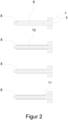
- FIG. 2 shows various embodiments of holding elements 5 according to the invention.
- the stop surface 8 is formed by a shoulder of the tension bolt 6.
- the holding element 5 comprises a sleeve, which is designated 10.
- the tension bolt 6 penetrates the sleeve 10, and the stop surface 8 is formed by the end of the sleeve 10, which is oriented towards the winding head carrier 4.
- the support body 7 comprises a sleeve-like protuberance, wherein the stop surface 8 is arranged at the end of the protuberance.
- the support bodies 7 are only partially arranged radially outside the winding elements 3, since the sleeve-shaped protuberance thereof protrudes between the winding elements 3.
- This protuberance can also serve to support the winding elements held by the respective holding element in the lateral direction.
- a further embodiment results from a combination of the last two embodiments, in that a shorter sleeve 10 is combined with a correspondingly shorter protrusion of the support body 7.
- the stop surface 8 is formed by the end of the sleeve 10.
- the tension bolt 6 comprises a shoulder, which is designated 11 and which presses against a sleeve 10 when screwed in.
- the stop surface 8 is also formed here by the end of the sleeve 10.
- This embodiment has the advantage that the support body 7 is largely relieved
- Further embodiments result from the use of several sleeves 10 per tension bolt 6, wherein the sleeves 10 are pressed against one another when the associated tension bolt 6 is screwed in.
Landscapes
- Engineering & Computer Science (AREA)
- Power Engineering (AREA)
- Insulation, Fastening Of Motor, Generator Windings (AREA)
Description
- Die Erfindung betrifft einen Rotor für eine elektrische Maschine, insbesondere für eine läufergespeiste Schleifringläufermaschine, wie sie für drehzahlregelbare Wasserkraft-Motor-Generatoren für Pumpspeicherkraftwerke zum Einsatz kommen.
- Die
DE 10 2010 020 415 A1 offenbart einen Rotor, welcher für einen drehzahlregelbaren Wasserkraft-Motor-Generator geeignet ist. Der in dieser Schrift offenbarte Rotor umfasst Wicklungselemente, welche in axial verlaufenden Nuten eines Rotorkörpers angeordnet sind, einen Wickelkopf, welcher axial neben dem Rotorkörper angeordnet ist, und einen Wickelkopfträger, wobei der Wickelkopf über Zugbolzen mit dem Wickelkopfträger verbunden ist. Dabei greifen die Zugbolzen an ihrem radial äußeren Enden an Stützkörper an, welche ihrerseits auf den Wicklungselementen im Bereich des Wickelkopfs aufliegen. Jedes Wicklungselement wird so von jeweils zwei Zugbolzen mittels je einem Stützkörper pro Zugbolzen im Bereich eines Wickelkopfes gehalten. Beim Festziehen der Zugbolzen ergib sich dabei die Schwierigkeit, dass durch die Kraft, die dabei auf die Wicklungselemente ausgeübt wird, dieselben geringfügig nach innen gebogen werden können. Das kann dazu führen, dass beim Festziehen des zweiten Zugbolzens eines betreffenden Wicklungselementes der zuvor festgezogene zugehörige Zugbolzen nicht mehr ausreichend unter Zug steht und sich daher mit der Zeit durch die im Betrieb wirksamen Vibrationen lösen kann. - Einen weiteren gattungsgemäßen Rotor offenbart die
CN 204 243 955 U . - Die Aufgabe der Erfindung ist es, eine Anordnung anzugeben, bei der das genannte Problem vermieden werden kann.
- Die Aufgabe wird erfindungsgemäß durch eine Ausführung entsprechend dem unabhängigen Anspruch gelöst. Weitere vorteilhafte Ausführungsformen der vorliegenden Erfindung finden sich in den Unteransprüchen.
- Im Folgenden wird die Erfindung anhand von Figuren erläutert. Die Figuren zeigen im Einzelnen:
- Fig.1
- Erfindungsgemäßer Rotor
- Fig.2
- Ausführungsformen der erfindungsgemäßen Haltebaugruppe
-
Figur 1 zeigt einen erfindungsgemäßen Rotor in schematischer Darstellung. Dabei ist inFigur 1 nur ein Ausschnitt des Rotors dargestellt. Der Rotor ist mit 1 bezeichnet. Der Rotor 1 umfasst einen Rotorkörper, welcher mit 2 bezeichnet ist, und eine Vielzahl von Wicklungselementen, welche in axial verlaufenden Nuten des Rotorkörpers 2 angeordnet sind. Dabei bilden die Wicklungselemente in radialer Richtung zwei Lagen. Die Wicklungselemente ragen in axialer Richtung über den Rotorkörper 2 hinaus und bilden so einen sogenannten Wickelkopf, welcher axial neben dem Rotorkörper 2 angeordnet ist. Dabei ist jeweils ein Wicklungselement der einen Lage an seinem Ende mit dem Ende eines Wicklungselementes der anderen Lage verbunden. In Figur 3 ist ein Wicklungselemente mit 3 bezeichnet. - Damit die Wicklungselemente 3 durch die enormen Fliehkräfte, welche beim Betrieb der elektrischen Maschine wirken, nicht nach radial außen gebogen werden, müssen dieselben im Bereich des Wickelkopfes in ihrer Position gehalten werden. Dazu umfasst der Wickelkopf einen Wickelkopfträger, welcher in
Figur 1 mit 4 bezeichnet ist und eine Vielzahl von Halteelementen, von denen eines inFigur 1 mit 5 bezeichnet ist. Dabei umfasst jedes Halteelement 5 jeweils einen Zugbolzen und einen Stützkörper. InFigur 1 ist einer der Zugbolzen mit 6 und einer der Stützkörper mit 7 bezeichnet. Die Stützkörper 7 sind in radialer Richtung außerhalb der Wicklungselemente 3 angeordnet. Die Zugbolzen 6 durchdringen jeweils den zugehörigen Stützkörper 7 und sind mit einem Gewinde in den Wickelkopfträger 4 eingeschraubt. Dabei kann der Wickelkopfträger 4 auch aus mehreren Teilen bestehen, so dass die Zugbolzen 6 beispielsweise in Profilleisten eingeschraubt werden, welche in entsprechenden Nuten des Wickelkopfträgerkörpers angeordnet sind. Profilleisten und Wickelkopfträgerkörper sind dann Teile des Wickelkopfträgers 4. - Erfindungsgemäß umfassen die Halteelemente 5 eine Anschlagfläche 8, welche so ausgebildet ist, dass dieselbe beim Einschrauben der Zugbolzen 6 an den Wickelkopfträger 4 zum Anliegen kommen kann, um so die radiale Länge, mit der die Zugbolzen 6 aus dem Wickelkopfträger 4 herausragen, auf ein vordefiniertes Maß einzustellen. Dabei ist das vordefinierte Maß so bemessen, dass dabei die Stützkörper 7 in Ruhelage des Rotors 1 nicht gegen die Wicklungselemente 3 gepresst werden. D.h. in Ruhelage des Rotors 1 berühren die Stützkörper 7 idealerweise gerade die Wicklungselemente 3, wenn die Zugbolzen 6 so weit in den Wickelkopfträger 4 eingeschraubt werden, dass die Anschlagfläche 8 an den Wickelkopfträger 4 zum Anliegen kommt. Alternativ kann in der genannten Lage auch ein (kleiner) Zwischenraum zwischen Stützkörper 7 und Wicklungselemente 3 vorhanden sein.
- Dabei ist das Merkmal "dass die Stützkörper 7 in Ruhelage des Rotors 1 nicht gegen die Wicklungselemente 3 gepresst werden" so zu verstehen, dass die Druckkraft, die durch die angezogenen Zugbolzen 6 in Ruhelage des Rotors 1 auf die Wicklungselemente 3 übertragen wird, vernachlässigbar klein gegenüber der in den angezogenen Zugbolzen 6 wirkenden Zugkraft ist. Das ist dann der Fall, wenn die durch einen angezogenen Zugbolzen 6 auf die Wicklungselemente 3 übertragene Druckkraft kleiner als 15% der im betreffenden Zugbolzen 6 wirkenden Zugkraft ist.
- Die so ausgebildeten Anschlagflächen 8 verhindern einerseits, dass die Wicklungselemente 3 beim Einschrauben der Zugbolzen 6 verformt werden. Andererseits gewährleisten dieselben eine Verspannung der Schraubverbindung zwischen Zugbolzen 6 und Wickelkopfträger 4, so dass sich die Schraubverbindung, während dem Betrieb des Rotors 1, nicht lösen kann. Eine hohe Vorspannung der Zugbolzen 6 bewirkt außerdem, dass die während dem Betrieb zusätzlich auf die Zugbolzen 6 wirkende Kraft klein gegenüber der Vorspannkraft ist, wodurch sich die Lebensdauer der Zugbolzen 6 verlängert.
- Optional können die Halteelemente 5 ein elastisches Element umfassen, welches in dem Zwischenraum zwischen dem zugehörigen Stützkörper 7 und den vom betreffenden Halteelement 5 gehaltenen Wicklungselementen 3 angeordnet ist. In
Figur 1 ist ein solches elastisches Element mit 9 bezeichnet. Dabei sind die elastischen Elemente 9 so ausgelegt, dass dieselben in radialer Richtung geringfügig zusammengepresst werden, wenn die Zugbolzen 6 soweit eingeschraubt werden, bis die zugehörigen Anschlagflächen 8 zum Anliegen an den Wickelkopfträger 4 kommen. Dabei ist das Elastizitätsmodul der elastischen Elemente 9 so zu wählen, dass es bei dem genannten Zusammenpressen derselben nicht zu einer signifikanten Verformung der Wicklungselemente 3 kommen kann. Mit anderen Worten: Die elastischen Elemente 9 sind so ausgelegt, dass es zu keiner signifikanten Verformung der Wicklungselemente 3 kommen kann, wenn die Zugbolzen 6 soweit eingeschraubt werden, bis die zugehörigen Anschlagflächen 8 zum Anliegen an den Wickelkopfträger 4 kommen. -
Figur 2 zeigt verschiedene Ausführungsformen erfindungsgemäßer Haltelemente 5. In der oben gezeigten Ausführungsform wird die Anschlagfläche 8 durch einen Absatz des Zugbolzens 6 gebildet. In der von oben zweiten Ausführungsform umfasst das Halteelement 5 eine Hülse, welche mit 10 bezeichnet ist. Der Zugbolzen 6 durchdringt die Hülse 10, und die Anschlagfläche 8 wird durch das Ende der Hülse 10 gebildet, welche zum Wickelkopfträger 4 hin orientiert ist. In der von oben dritten Ausführungsform umfasst der Stützkörper 7 eine hülsenartige Ausstülpung, wobei die Anschlagfläche 8 am Ende der Ausstülpung angeordnet ist. Bei der letztgenannte Ausführungsform sind die Stützkörper 7 nur teilweise in radialer Richtung außerhalb der Wicklungselemente 3 angeordnet, da die hülsenförmige Ausstülpung derselben zwischen die Wicklungselemente 3 hineinragt. Diese Ausstülpung kann auch dazu dienen die durch das betreffende Halteelement gehaltenen Wicklungselemente in lateraler Richtung abzustützen. Eine weitere Ausführungsform ergibt sich durch eine Kombination der beiden letztgenannten Ausführungsformen, indem eine kürzere Hülse 10 mit einer entsprechend kürzeren Ausstülpung des Stützkörpers 7 kombiniert wird. Dabei wird die Anschlagfläche 8 durch das Ende der Hülse 10 gebildet. In der unteren inFigur 2 gezeigten Ausführungsform umfasst der Zugbolzen 6 einen Absatz, welcher mit 11 bezeichnet ist und welcher beim Einschrauben gegen eine Hülse 10 drückt. Die Anschlagfläche 8 wird auch hier durch das Ende der Hülse 10 gebildet. Bei dieser Ausführungsform ergibt sich der Vorteil, dass der Stützkörper 7 weitestgehend entlastet wird. Weitere Ausführungsformen ergeben sich durch die Verwendung mehrerer Hülsen 10 pro Zugbolzen 6, wobei die Hülsen 10 beim Einschrauben des zugehörigen Zugbolzens 6 gegeneinandergepresst werden. -
- 1
- Rotor
- 2
- Rotorkörper
- 3
- Wicklungselement
- 4
- Wickelkopfträger
- 5
- Halteelemente
- 6
- Zugbolzen
- 7
- Stützkörper
- 8
- Anschlagfläche
- 9
- Elastisches Element
- 10
- Hülse
- 11
- Absatz
Claims (6)
- Rotor (1) für eine elektrische Maschine mit einem Rotorkörper (2), einer Vielzahl von Wicklungselementen (3) und einem axial neben dem Rotorköper (2) angeordneten Wickelkopf, wobei die Wicklungselemente (3) in axial verlaufenden Nuten des Rotorkörpers (2) angeordnet sind, und wobei der Wickelkopf einen Wickelkopfträger (4) und eine Vielzahl von Halteelemente (5) umfasst, und wobei jedes Halteelement (5) jeweils einen Zugbolzen (6) und einen Stützkörper (7) umfasst, und wobei die Stützkörper (7) wenigstens teilweise in radialer Richtung außerhalb der Wicklungselemente (3) angeordnet sind, und wobei die Zugbolzen (6) jeweils den zugehörigen Stützkörper (7) durchdringen und mit einem Gewinde in den Wickelkopfträger (4) eingeschraubt sind, dadurch gekennzeichnet, dass die Halteelemente (5) jeweils eine Anschlagfläche (8) umfassen, welche so ausgebildet ist, dass dieselbe beim Einschrauben der Zugbolzen (7) an den Wickelkopfträger (4) zum Anliegen kommen kann, um so die radiale Länge, mit der die Zugbolzen (6) aus dem Wickelkopfträger (4) herausragen, auf ein vordefiniertes Maß einzustellen, wobei das vordefinierte Maß so bemessen ist, dass dabei die Stützkörper (7) in Ruhelage des Rotors (1) nicht gegen die Wicklungselemente (3) gepresst werden.
- Rotor (1) nach Anspruch 1, und wobei ein Halteelement (5) ein elastisches Element (9) umfasst, welches in einem Zwischenraum zwischen dem zugehörigen Stützkörper (7) und den vom Halteelement gehaltenen Wicklungselementen (3) angeordnet ist.
- Rotor (1) nach Anspruch 1 oder 2, und wobei eine Anschlagfläche (8) durch einen Absatz des Zugbolzens (6) gebildet wird.
- Rotor (1) nach Anspruch 1 oder 2, und wobei ein Halteelement (5) eine Hülse (10) umfasst, und wobei der Zugbolzen (6) die Hülse (10) durchdringt, und wobei die Anschlagfläche (8) durch das Ende der Hülse (10) gebildet wird, welche zum Wickelkopfträger (4) hin orientiert angeordnet ist.
- Rotor (1) nach Anspruch 4, wobei der Zugbolzen (6) einen Absatz (11) umfasst, welcher beim Anziehen des Zugbolzens (6) gegen die Hülse (10) gepresst werden kann.
- Rotor (1) nach Anspruch 1 oder 2, und wobei ein Stützkörper (7) eine hülsenartige Ausstülpung umfasst, und wobei die Anschlagfläche (8) am Ende der Ausstülpung angeordnet ist.
Applications Claiming Priority (2)
| Application Number | Priority Date | Filing Date | Title |
|---|---|---|---|
| DE102022103999 | 2022-02-21 | ||
| PCT/EP2023/053591 WO2023156370A1 (de) | 2022-02-21 | 2023-02-14 | Rotor für eine elektrische maschine |
Publications (2)
| Publication Number | Publication Date |
|---|---|
| EP4483479A1 EP4483479A1 (de) | 2025-01-01 |
| EP4483479B1 true EP4483479B1 (de) | 2025-04-30 |
Family
ID=85251660
Family Applications (1)
| Application Number | Title | Priority Date | Filing Date |
|---|---|---|---|
| EP23705364.0A Active EP4483479B1 (de) | 2022-02-21 | 2023-02-14 | Rotor für eine elektrische maschine |
Country Status (5)
| Country | Link |
|---|---|
| US (1) | US20240413695A1 (de) |
| EP (1) | EP4483479B1 (de) |
| CN (1) | CN118525438A (de) |
| CA (1) | CA3244759A1 (de) |
| WO (1) | WO2023156370A1 (de) |
Family Cites Families (4)
| Publication number | Priority date | Publication date | Assignee | Title |
|---|---|---|---|---|
| DE701612C (de) * | 1937-08-20 | 1941-01-20 | Siemens Schuckertwerke Akt Ges | Spulenkopfbefestigung fuer Laeuferwicklungen elektrischer Maschinen |
| DE19519127C1 (de) * | 1995-05-16 | 1996-09-12 | Siemens Ag | Dynamoelektrische Maschine mit bewickeltem Rotor |
| DE102010020415A1 (de) | 2010-05-12 | 2011-11-17 | Voith Patent Gmbh | Rotor für eine dynamoelektrische Maschine |
| CN204243955U (zh) * | 2014-09-16 | 2015-04-01 | 哈尔滨电机厂有限责任公司 | 水轮发电机转子引线固定装置 |
-
2023
- 2023-02-14 EP EP23705364.0A patent/EP4483479B1/de active Active
- 2023-02-14 CN CN202380016248.4A patent/CN118525438A/zh active Pending
- 2023-02-14 WO PCT/EP2023/053591 patent/WO2023156370A1/de not_active Ceased
- 2023-02-14 CA CA3244759A patent/CA3244759A1/en active Pending
-
2024
- 2024-08-20 US US18/809,813 patent/US20240413695A1/en active Pending
Also Published As
| Publication number | Publication date |
|---|---|
| CA3244759A1 (en) | 2025-01-20 |
| CN118525438A (zh) | 2024-08-20 |
| EP4483479A1 (de) | 2025-01-01 |
| WO2023156370A1 (de) | 2023-08-24 |
| US20240413695A1 (en) | 2024-12-12 |
Similar Documents
| Publication | Publication Date | Title |
|---|---|---|
| DE112008001909B4 (de) | Verbindungsleitung für einen Stator eines Elektromotors, die Verbindungsleitung aufweisender Stator und Verfahren zum Biegen der Verbindungsleitung | |
| DE102004030830B4 (de) | Bremsenaufbau für eine Traktionsmaschine | |
| DE102009057782A1 (de) | Stator für rotierende elektrische Maschine | |
| EP0669694A1 (de) | Vorrichtung zur Halterung der Windungsenden einer Statorwicklung in einer dynamoelektrischen Maschine | |
| EP2685607A1 (de) | Fixierung von Permanentmagneten an einem Rotor | |
| EP0171571A1 (de) | Statorkörper mit lamellierten Pressplatten | |
| DE10230158B4 (de) | Klemm-Mechanismus für eine Lenksäule | |
| EP2630702B1 (de) | Kohlebürste mit abschaltvorrichtung | |
| EP4483479B1 (de) | Rotor für eine elektrische maschine | |
| DE102008064500B4 (de) | Elektrische Maschine mit Abstützung der Wicklungsschaltung am Statorblechpaket | |
| DE102007050803A1 (de) | Bürstenvorrichtung mit einer Feder für eine Elektromaschine | |
| EP4483476B1 (de) | Wickelkopfhalterung eines rotors für eine elektrische maschine | |
| DE19927279B4 (de) | Käfigläufer für eine elektrische Maschine | |
| WO2021004676A1 (de) | Rotor für eine elektrische maschine | |
| DE10310306A1 (de) | Vorrichtung zum Spannen einer Statorwicklung | |
| DE102018213128A1 (de) | Gehäuseanordnung eines Elektromotors | |
| DE102019218196A1 (de) | Elektromotorisch angetriebenes Aggregat für ein Fahrzeug | |
| AT525718A1 (de) | Rotor | |
| DE9416348U1 (de) | Wellenverbindung für einen Stromerzeuger | |
| EP1798417B1 (de) | Vakuumpumpe | |
| WO2021004675A1 (de) | Rotor für eine elektrische maschine | |
| DE102019213574A1 (de) | Rotor einer elektrischen Maschine | |
| EP3690902B1 (de) | Vorrichtung zum pressen eines eine oder mehrere wicklungen aufweisenden blockes einer statischen elektrischen maschine | |
| DE102022209388A1 (de) | Ruderanlage | |
| DE102023202317A1 (de) | Elektrische Maschine für ein Kraftfahrzeug und Bremseinrichtung |
Legal Events
| Date | Code | Title | Description |
|---|---|---|---|
| STAA | Information on the status of an ep patent application or granted ep patent |
Free format text: STATUS: UNKNOWN |
|
| STAA | Information on the status of an ep patent application or granted ep patent |
Free format text: STATUS: THE INTERNATIONAL PUBLICATION HAS BEEN MADE |
|
| PUAI | Public reference made under article 153(3) epc to a published international application that has entered the european phase |
Free format text: ORIGINAL CODE: 0009012 |
|
| STAA | Information on the status of an ep patent application or granted ep patent |
Free format text: STATUS: REQUEST FOR EXAMINATION WAS MADE |
|
| 17P | Request for examination filed |
Effective date: 20240923 |
|
| AK | Designated contracting states |
Kind code of ref document: A1 Designated state(s): AL AT BE BG CH CY CZ DE DK EE ES FI FR GB GR HR HU IE IS IT LI LT LU LV MC ME MK MT NL NO PL PT RO RS SE SI SK SM TR |
|
| GRAP | Despatch of communication of intention to grant a patent |
Free format text: ORIGINAL CODE: EPIDOSNIGR1 |
|
| STAA | Information on the status of an ep patent application or granted ep patent |
Free format text: STATUS: GRANT OF PATENT IS INTENDED |
|
| GRAS | Grant fee paid |
Free format text: ORIGINAL CODE: EPIDOSNIGR3 |
|
| GRAA | (expected) grant |
Free format text: ORIGINAL CODE: 0009210 |
|
| STAA | Information on the status of an ep patent application or granted ep patent |
Free format text: STATUS: THE PATENT HAS BEEN GRANTED |
|
| DAV | Request for validation of the european patent (deleted) | ||
| DAX | Request for extension of the european patent (deleted) | ||
| INTG | Intention to grant announced |
Effective date: 20250317 |
|
| AK | Designated contracting states |
Kind code of ref document: B1 Designated state(s): AL AT BE BG CH CY CZ DE DK EE ES FI FR GB GR HR HU IE IS IT LI LT LU LV MC ME MK MT NL NO PL PT RO RS SE SI SK SM TR |
|
| REG | Reference to a national code |
Ref country code: CH Ref legal event code: EP Ref country code: GB Ref legal event code: FG4D Free format text: NOT ENGLISH |
|
| REG | Reference to a national code |
Ref country code: DE Ref legal event code: R096 Ref document number: 502023000914 Country of ref document: DE |
|
| REG | Reference to a national code |
Ref country code: IE Ref legal event code: FG4D Free format text: LANGUAGE OF EP DOCUMENT: GERMAN |
|
| REG | Reference to a national code |
Ref country code: NL Ref legal event code: MP Effective date: 20250430 |
|
| PG25 | Lapsed in a contracting state [announced via postgrant information from national office to epo] |
Ref country code: FI Free format text: LAPSE BECAUSE OF FAILURE TO SUBMIT A TRANSLATION OF THE DESCRIPTION OR TO PAY THE FEE WITHIN THE PRESCRIBED TIME-LIMIT Effective date: 20250430 Ref country code: ES Free format text: LAPSE BECAUSE OF FAILURE TO SUBMIT A TRANSLATION OF THE DESCRIPTION OR TO PAY THE FEE WITHIN THE PRESCRIBED TIME-LIMIT Effective date: 20250430 Ref country code: PT Free format text: LAPSE BECAUSE OF FAILURE TO SUBMIT A TRANSLATION OF THE DESCRIPTION OR TO PAY THE FEE WITHIN THE PRESCRIBED TIME-LIMIT Effective date: 20250901 |
|
| REG | Reference to a national code |
Ref country code: LT Ref legal event code: MG9D |
|
| PG25 | Lapsed in a contracting state [announced via postgrant information from national office to epo] |
Ref country code: NO Free format text: LAPSE BECAUSE OF FAILURE TO SUBMIT A TRANSLATION OF THE DESCRIPTION OR TO PAY THE FEE WITHIN THE PRESCRIBED TIME-LIMIT Effective date: 20250730 Ref country code: GR Free format text: LAPSE BECAUSE OF FAILURE TO SUBMIT A TRANSLATION OF THE DESCRIPTION OR TO PAY THE FEE WITHIN THE PRESCRIBED TIME-LIMIT Effective date: 20250731 |
|
| PG25 | Lapsed in a contracting state [announced via postgrant information from national office to epo] |
Ref country code: PL Free format text: LAPSE BECAUSE OF FAILURE TO SUBMIT A TRANSLATION OF THE DESCRIPTION OR TO PAY THE FEE WITHIN THE PRESCRIBED TIME-LIMIT Effective date: 20250430 Ref country code: NL Free format text: LAPSE BECAUSE OF FAILURE TO SUBMIT A TRANSLATION OF THE DESCRIPTION OR TO PAY THE FEE WITHIN THE PRESCRIBED TIME-LIMIT Effective date: 20250430 |
|
| PG25 | Lapsed in a contracting state [announced via postgrant information from national office to epo] |
Ref country code: BG Free format text: LAPSE BECAUSE OF FAILURE TO SUBMIT A TRANSLATION OF THE DESCRIPTION OR TO PAY THE FEE WITHIN THE PRESCRIBED TIME-LIMIT Effective date: 20250430 |
|
| PG25 | Lapsed in a contracting state [announced via postgrant information from national office to epo] |
Ref country code: HR Free format text: LAPSE BECAUSE OF FAILURE TO SUBMIT A TRANSLATION OF THE DESCRIPTION OR TO PAY THE FEE WITHIN THE PRESCRIBED TIME-LIMIT Effective date: 20250430 |
|
| PG25 | Lapsed in a contracting state [announced via postgrant information from national office to epo] |
Ref country code: RS Free format text: LAPSE BECAUSE OF FAILURE TO SUBMIT A TRANSLATION OF THE DESCRIPTION OR TO PAY THE FEE WITHIN THE PRESCRIBED TIME-LIMIT Effective date: 20250731 |
|
| PG25 | Lapsed in a contracting state [announced via postgrant information from national office to epo] |
Ref country code: IS Free format text: LAPSE BECAUSE OF FAILURE TO SUBMIT A TRANSLATION OF THE DESCRIPTION OR TO PAY THE FEE WITHIN THE PRESCRIBED TIME-LIMIT Effective date: 20250830 |
|
| PG25 | Lapsed in a contracting state [announced via postgrant information from national office to epo] |
Ref country code: LV Free format text: LAPSE BECAUSE OF FAILURE TO SUBMIT A TRANSLATION OF THE DESCRIPTION OR TO PAY THE FEE WITHIN THE PRESCRIBED TIME-LIMIT Effective date: 20250430 |