EP4482409B1 - Abnehmbare getriebemotoranordnung zur motorisierung einer strebe in einem räumlichen rahmen - Google Patents
Abnehmbare getriebemotoranordnung zur motorisierung einer strebe in einem räumlichen rahmen Download PDFInfo
- Publication number
- EP4482409B1 EP4482409B1 EP23718398.3A EP23718398A EP4482409B1 EP 4482409 B1 EP4482409 B1 EP 4482409B1 EP 23718398 A EP23718398 A EP 23718398A EP 4482409 B1 EP4482409 B1 EP 4482409B1
- Authority
- EP
- European Patent Office
- Prior art keywords
- motor
- geared
- assembly
- strut
- assemblies
- Prior art date
- Legal status (The legal status is an assumption and is not a legal conclusion. Google has not performed a legal analysis and makes no representation as to the accuracy of the status listed.)
- Active
Links
Images


Classifications
-
- A—HUMAN NECESSITIES
- A61—MEDICAL OR VETERINARY SCIENCE; HYGIENE
- A61B—DIAGNOSIS; SURGERY; IDENTIFICATION
- A61B17/00—Surgical instruments, devices or methods
- A61B17/56—Surgical instruments or methods for treatment of bones or joints; Devices specially adapted therefor
- A61B17/58—Surgical instruments or methods for treatment of bones or joints; Devices specially adapted therefor for osteosynthesis, e.g. bone plates, screws or setting implements
- A61B17/60—Surgical instruments or methods for treatment of bones or joints; Devices specially adapted therefor for osteosynthesis, e.g. bone plates, screws or setting implements for external osteosynthesis, e.g. distractors, contractors
- A61B17/62—Ring frames, i.e. devices extending around the bones to be positioned
-
- A—HUMAN NECESSITIES
- A61—MEDICAL OR VETERINARY SCIENCE; HYGIENE
- A61B—DIAGNOSIS; SURGERY; IDENTIFICATION
- A61B17/00—Surgical instruments, devices or methods
- A61B17/56—Surgical instruments or methods for treatment of bones or joints; Devices specially adapted therefor
- A61B17/58—Surgical instruments or methods for treatment of bones or joints; Devices specially adapted therefor for osteosynthesis, e.g. bone plates, screws or setting implements
- A61B17/60—Surgical instruments or methods for treatment of bones or joints; Devices specially adapted therefor for osteosynthesis, e.g. bone plates, screws or setting implements for external osteosynthesis, e.g. distractors, contractors
- A61B17/64—Devices extending alongside the bones to be positioned
- A61B17/645—Devices extending alongside the bones to be positioned comprising a framework
-
- A—HUMAN NECESSITIES
- A61—MEDICAL OR VETERINARY SCIENCE; HYGIENE
- A61B—DIAGNOSIS; SURGERY; IDENTIFICATION
- A61B17/00—Surgical instruments, devices or methods
- A61B17/56—Surgical instruments or methods for treatment of bones or joints; Devices specially adapted therefor
- A61B17/58—Surgical instruments or methods for treatment of bones or joints; Devices specially adapted therefor for osteosynthesis, e.g. bone plates, screws or setting implements
- A61B17/60—Surgical instruments or methods for treatment of bones or joints; Devices specially adapted therefor for osteosynthesis, e.g. bone plates, screws or setting implements for external osteosynthesis, e.g. distractors, contractors
- A61B17/66—Alignment, compression or distraction mechanisms
-
- A—HUMAN NECESSITIES
- A61—MEDICAL OR VETERINARY SCIENCE; HYGIENE
- A61B—DIAGNOSIS; SURGERY; IDENTIFICATION
- A61B90/00—Instruments, implements or accessories specially adapted for surgery or diagnosis and not covered by any of the groups A61B1/00 - A61B50/00, e.g. for luxation treatment or for protecting wound edges
- A61B90/10—Instruments, implements or accessories specially adapted for surgery or diagnosis and not covered by any of the groups A61B1/00 - A61B50/00, e.g. for luxation treatment or for protecting wound edges for stereotaxic surgery, e.g. frame-based stereotaxis
- A61B90/14—Fixators for body parts, e.g. skull clamps; Constructional details of fixators, e.g. pins
-
- A—HUMAN NECESSITIES
- A61—MEDICAL OR VETERINARY SCIENCE; HYGIENE
- A61B—DIAGNOSIS; SURGERY; IDENTIFICATION
- A61B17/00—Surgical instruments, devices or methods
- A61B2017/00017—Electrical control of surgical instruments
- A61B2017/00221—Electrical control of surgical instruments with wireless transmission of data, e.g. by infrared radiation or radiowaves
-
- A—HUMAN NECESSITIES
- A61—MEDICAL OR VETERINARY SCIENCE; HYGIENE
- A61B—DIAGNOSIS; SURGERY; IDENTIFICATION
- A61B17/00—Surgical instruments, devices or methods
- A61B2017/00367—Details of actuation of instruments, e.g. relations between pushing buttons, or the like, and activation of the tool, working tip, or the like
- A61B2017/00398—Details of actuation of instruments, e.g. relations between pushing buttons, or the like, and activation of the tool, working tip, or the like using powered actuators, e.g. stepper motors, solenoids
Definitions
- the present disclosure relates generally to orthopedic devices, systems, and methods for facilitating fracture alignment such as the treatment of musculoskeletal conditions with a spatial frame, and particularly to a geared-motor assembly selectively attached and detached from a manually adjustable strut.
- the struts can be manually adjusted (e.g., rotated) to, for example, facilitate initial construction of the spatial frame in the operating room, to allow patients to manually adjust the struts if desired, etc.
- motorized and/or automated adjustment of the struts according to a treatment plan can be achieved.
- a person that suffers a bone fracture is required to use a bone alignment device, an external fixation system, etc. such as, for example, a spatial frame, a hexapod, etc. (terms used interchangeably herein without the intent to limit or distinguish) to align two or more bones, bone fragments, bone pieces, etc. (terms used interchangeably herein without the intent to limit or distinguish).
- a bone alignment device such as, for example, a spatial frame, a hexapod, etc.
- a hexapod etc.
- spatial frames allow for polyaxial movement of the coupled bones and are typically used to keep fractured bones stabilized and in alignment during a treatment period.
- the spatial frame includes first and second rings, platforms, frames, bases, etc. (terms used interchangeably herein without the intent to limit or distinguish) intercoupled by a plurality of struts.
- the struts have adjustable lengths that may be manually adjusted regularly (e.g., daily) in accordance with a prescription or treatment plan (terms used interchangeably herein without the intent to limit or distinguish).
- a prescription or treatment plan (terms used interchangeably herein without the intent to limit or distinguish).
- the treatment plan specifies strut length adjustments to be made to each of the struts over time to ensure successful bone alignment.
- TAYLOR SPATIAL FRAME ® manufactured and sold by Smith Nephew, Inc.
- the TAYLOR SPATIAL FRAME ® is based on the general concept of a Stewart platform. Smith & Nephew, Inc. is the owner of U.S. Patent Nos. 5,702,389 ; 5,728,095 ; 5,891,143 ; RE40,914 , 5,971,984 ; 6,030,386 ; and 6,129,727 ; and U.S. Published Patent Application Nos. 20030191466 ; 2004/0073211 ; 2005/0215997 ; and 2016/0092651 that disclose many concepts of and improvements to the Stewart platform based spatial frame, including methods of use, systems, and devices that enhance use of the spatial frame.
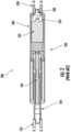
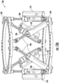
- the spatial frame 100 may form a hexapod having a circular, metal frame with a first platform 102 and a second platform 104 connected by six adjustable length struts 106 (labeled as struts 106-1 through 106-6 in FIG. 1 ). Each strut 106 may be independently lengthened or shortened relative to the rest of the frame, thereby allowing for six different axes of movement.
- Each strut 106 may include an outer body and an inner body, which may be configured as, or be operatively coupled to, a threaded rod (also referred to as a lead screw).
- the outer body may be coupled to one of the platforms, such as, the second platform 104 by way of a joint as shown.
- the inner body may be coupled to the other platform, such as, the first platform 102 by way of a joint as shown.
- the outer body and the inner body may be moved or translated relative to one another.
- the strut 106 may include an adjustment nut wherein rotation of the adjustment nut moves the inner body (e.g., threaded rod or lead screw) relative to the outer body to adjust an overall length of the strut.
- the spatial frame 100 may be used to treat a variety of skeletal fractures of a patient.
- the spatial frame 100 is positioned around the patient and is used to align two or more bone portions.
- a length of each strut 106 may be incrementally adjusted (e.g., shortened or lengthened) in accordance with a treatment plan that specifies adjustments to be made to each strut 106 over time to ensure successful bone alignment.
- the length of each strut 106 should be adjusted daily to comply with the provided treatment plan. Adjusting the length of each strut 106 adjusts the distance and/or position between the first and second platforms 102, 104, and hence the first and second bone portions coupled thereto.
- the geared-motor assembly includes a worm-drive mechanism to couple the output shaft of the motor to the threaded rod of the strut.
- the output shaft of the motor includes, or is formed in, a worm drive.
- the worm drive being coupled to a first end of an intermediate shaft.
- a second end of the intermediate shaft including a gear coupled to a corresponding gear on the threaded rod of the strut.
- gear of the threaded rod and the gear at the second end of the intermediate shaft are beveled gears.
- each of the geared-motor assemblies may include a wireless communication chip arranged and configured to communicate with an external computing system to, for example, exchange data relating to strut position, exchange data relating to and updating the prescribed treatment plan, and exchange data related to the progression of bone healing and frame alignment, etc.
- each geared-motor assembly may include a self-contained microprocessor, which can receive and update the treatment plan as needed.
- the microprocessor is configured to control operation of the geared-motor assemblies, and hence the struts, without the need for a separate centralized control unit positioned within the spatial frame (e.g., coupled to one of the platforms).
- each of the geared-motor assemblies may include a power supply such as, for example, a battery to power the geared-motor assembly including, for example, the motor and any other circuity contained therein.
- the geared-motor assemblies may include a sensor such as, for example, an accelerometer or acoustic emission sensor for detecting faults in the gear train such as, for example, misalignment of the gears (e.g., pinion gears) via vibrational analysis or acoustic emission respectively, which may occur when the geared-motor assembly is removed and re-installed after an X-ray or strut change.
- a sensor such as, for example, an accelerometer or acoustic emission sensor for detecting faults in the gear train such as, for example, misalignment of the gears (e.g., pinion gears) via vibrational analysis or acoustic emission respectively, which may occur when the geared-motor assembly is removed and re-installed after an X-ray or strut change.
- a spatial frame including a first platform; a second platform spaced from the first platform; a plurality of adjustable length struts, each of the plurality of adjustable length struts coupled to the first platform and the second platform, each of the adjustable length struts including a housing and a threaded rod, wherein the threaded rod is arranged and configured to move relative to the housing to adjust a length of the strut; and a plurality of geared-motor assemblies, each of the plurality of geared-motor assemblies being arranged and configured to couple to one of the plurality of adjustable length struts, wherein each of the plurality of geared-motor assemblies is arranged and configured as a self-contained unit including electronics and power supply to (i) wirelessly communicate with an external computing device and (ii) to adjust the length of the strut to which it is coupled.
- each of the plurality of geared-motor assemblies is devoid of any external wires for coupling to an external controller.
- each of the geared-motor assemblies includes a housing; a motor including an output shaft and a gear; a printed-circuit board including a microprocessor and a wireless communication chip; and a power supply arranged and configured to provide power to the motor and printed-circuit board.
- one of the plurality of geared-motor assemblies is configured as a primary assembly arranged and configured to communicate with an external computing device to receive instructions and to transmit instructions to the remaining secondary assemblies.
- the primary assembly is selectively interchangeable such that responsibilities associated with the primary assembly can be transferred to one of the secondary assemblies.
- responsibilities associated with the primary assembly are transferred to one of the secondary assemblies based on remaining power supply of the primary assembly.
- responsibilities associated with the primary assembly are transferred to one of the secondary assemblies when a remaining power supply level of the primary assembly is below a threshold value.
- responsibilities associated with the primary assembly are transferred to one of the secondary assemblies based on a predetermined schedule.
- responsibilities associated with the primary assembly are transferred to one of the secondary assemblies at a predetermined time.
- responsibilities associated with the primary assembly are transferred to one of the secondary assemblies based on at least data received by the primary assembly from at least one secondary assembly.
- the data includes at least one of the following: a power supply level of at least one secondary assembly, a load level of at least one secondary assembly, a frequency of adjustments performed by at least one secondary assembly, a length of adjustments performed by at least one secondary assembly, one or more positioning coordinates of at least one secondary assembly, an angle of adjustments performed by at least one secondary assembly, a direction of adjustments of the at least one secondary assembly, and any combination thereof.
- responsibilities associated with the primary assembly are transferred to one of the secondary assemblies based on at least one of: a load data of the primary assembly, a load data of at least one secondary assembly, a power supply level of the primary assembly, a power supply level of the at least one secondary assembly, and any combination thereof.
- responsibilities associated with the primary assembly are transferred to one of the secondary assemblies in accordance with a prescription plan determined for the spatial frame.
- responsibilities associated with the primary assembly are transferred to one of the secondary assemblies based on an instruction received from one or more external devices communicatively coupled to at least one of the primary assembly and at least one secondary assembly.
- each of the plurality of struts include a gear coupled to the threaded rod and each of the plurality of geared-motor assemblies include a housing, a motor including an output shaft and a gear associated therewith, the gear of the motor arranged and configured to be operatively coupled to the gear of the strut.
- each of the geared-motor assemblies further include one or more idler gears arranged and configured to engage the gear of the motor and the gear of the strut.
- the gear of the strut is at least partially contained within the housing of the strut, the housing of the strut including an opening for providing access to the gear, and the housing of the geared-motor assembly includes an opening to enable one of the gear of the motor and one of the one or more idler gears to extend therethrough.
- the housing of the strut further includes a first recess and a peg recess; and the housing of the geared-motor assembly includes a first projection and a spring-loaded peg extending from a surface thereof, the first recess formed in the housing of the strut arranged and configured to receive the first projection of the geared-motor assembly.
- the geared-motor assembly can be rotated relative to the strut.
- housing of the strut further includes a removal hole in communication with the peg recess so that a tool can be inserted to facilitate removal of the spring-loaded peg from the peg recess to enable the geared-motor assembly to be disengaged from the strut.
- detachable geared-motor assembly Various features or the like of a detachable geared-motor assembly will now be described more fully herein with reference to the accompanying drawings, in which one or more features of the detachable geared-motor assembly will be shown and described. It should be appreciated that the various features may be used independently of, or in combination, with each other. It will be appreciated that the detachable geared-motor assembly as disclosed herein may be embodied in many different forms and may selectively include one or more concepts, features, or functions described herein. As such, the detachable geared-motor assembly should not be construed as being limited to the specific examples set forth herein. Rather, these examples are provided so that this disclosure will convey certain features of the geared-motor assembly to those skilled in the art.
- a geared-motor assembly is disclosed.
- the geared-motor assembly may be arranged and configured as a self-contained unit arranged and configured to receive and transmit data with an external computing system.
- the geared-motor assembly including an enclosure or housing containing a motor, a power supply, a microprocessor, and all other power and control circuity needed to engage and control a manually adjustable strut in a spatial frame.
- each geared-motor assembly may include a motor and a torque transmitting mechanism such as, for example, a gear, arranged and configured to engage a corresponding gear on a manually adjustable strut in a spatial frame.
- actuation of the motor enables motorized rotation of the torque transmitting mechanism and thus the manually adjustable strut coupled to the geared-motor assembly.
- each geared-motor assembly may include a microcontroller or microprocessor (terms used interchangeably herein without the intent to limit or distinguish) arranged and configured to control operation of the geared-motor assembly including, for example, receiving and/or updating a treatment plan, and/or controlling activation of the motor without the need for a separate centralized control unit positioned within the spatial frame.
- each of the detachable geared-motor assemblies may be coupled to one of the manually adjustable struts.
- the spatial frame can be selectively configured to operate in either of a first or manually adjustable mode or configuration of operation wherein each strut may be manually adjusted or a second or motorized mode or configuration of operation wherein a geared-motor assembly may be coupled to each strut to facilitate motorized adjustment of the struts.
- the plurality of struts can be manually adjusted.
- the adjustments can be motorized and/or automated, thereby providing greater flexibility to doctors and patients in carrying out the prescribed treatment plan.
- an offset motor design is achieved thereby enabling a shorter minimum strut length to be achieved (e.g., the geared-motor assemblies and struts may be arranged and configured with a shorter minimum length (e.g., length of the strut as measured end to end (e.g., joint to joint) with the threaded rod assembly in the fully retracted position) as compared to conventional in-line motorized struts, while still providing a reasonable working length (e.g., adjustment length of the strut in use - length adjustment or difference between the minimum length and the maximum length of the strut).
- a shorter minimum length e.g., length of the strut as measured end to end (e.g., joint to joint) with the threaded rod assembly in the fully retracted position
- a reasonable working length e.g., adjustment length of the strut in use - length adjustment or difference between the minimum length and the maximum length of the strut.
- the removable geared-motor assembly 400 is arranged and configured to engage, attach, couple, etc. to the manually adjustable struts 106 of the spatial frame 300.
- the spatial frame 300 can be operated in and switched between two modes or configurations of operation.
- the struts 106 may be manually adjustable as illustrated in FIG. 3A .
- a geared-motor assembly 400 may be attached to one or more of the manually adjustable struts 106 to enable motorized and/or automated adjustment of the struts.
- the geared-motor assemblies 400 are coupled to the manually adjustable struts 106 of the spatial frame 300.
- the geared-motor assemblies 400 may be coupled to the manually adjustable struts 106 after surgery in clinic by, for example, a primary care provider.
- the geared-motor assemblies 400 may be coupled to the manually adjustable struts 106 at any time and by anyone.
- the geared-motor assemblies 400 may facilitate motorized and/or automated adjustments such as, for example, semi-continuous actuation.
- the geared-motor assemblies 400 may enable motorized adjustments to be made autonomously via a companion APP running on, for example, a smartphone, a tablet, or other external computing system.
- the spatial frame and/or system architecture may be arranged and configured to automatically adjust the motorized struts according to the prescribed treatment plan (e.g., automatically adjust the plurality of struts without patient intervention).
- the spatial frame and/or system architecture may be arranged and configured to require patient and/or caregiver activation to begin the process of automatically adjusting the struts according to the prescribed treatment plan.
- the spatial frame may be arranged to intermittently auto-adjust the motorized struts at predetermined times according to the treatment plan.
- the spatial frame may be arranged to intermittently auto-adjust the motorized struts at selected times when convenient and/or when selected by the patient.
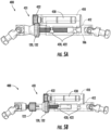
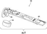
- the geared-motor assemblies 400 may each include an enclosure or housing 410, a coupling mechanism 420 for coupling the geared-motor assembly 400 to the strut 106, a motor 430, a torque transferring mechanism 431 (e.g., a transmission or gears for transferring rotation from the motor 430 to the strut 106), and all necessary components and circuity so that activation of the motor 430 moves the strut 106.
- a coupling mechanism 420 for coupling the geared-motor assembly 400 to the strut 106
- a motor 430 for coupling the geared-motor assembly 400 to the strut 106
- a torque transferring mechanism 431 e.g., a transmission or gears for transferring rotation from the motor 430 to the strut 106
- the gear-motor assemblies 400 may include one or more microprocessors, sensors such as, for example, positional sensors to monitor the length of the struts, load sensors or accelerometer for providing biomechanical feedback during bone healing and acoustic emission or vibration sensor for fault level detection in the gear train, a wireless communication chip or antenna for facilitating wireless communication and/or transfer of data, a power supply such as, for example, a battery, a charging circuit, etc.
- sensors such as, for example, positional sensors to monitor the length of the struts, load sensors or accelerometer for providing biomechanical feedback during bone healing and acoustic emission or vibration sensor for fault level detection in the gear train
- a wireless communication chip or antenna for facilitating wireless communication and/or transfer of data
- a power supply such as, for example, a battery, a charging circuit, etc.
- detachable geared-motor assemblies 400 By utilizing detachable geared-motor assemblies 400, motorized and/or automated adjustments of a spatial frame can be achieved.
- the detachable geared-motor assemblies 400 are arranged and configured to engage a manually adjustable strut 106 in an outpatient setting thus enabling the spatial frame to be operated in two different modes or configurations: (a) a standard, manual adjustment mode where the lengths of the struts 106 can be adjusted by manual rotation of a threaded adjustment nut and (b) motorized and/or automated adjustment via the detachable geared-motor assemblies 400.
- the geared-motor assemblies 400 by arranging the geared-motor assemblies 400 as self-contained units or devices incorporating wireless, self-powered, and incorporating their own microprocessors (e.g., in some examples, the geared-motor assemblies 400 are arranged and configured as a self-contained unit including all of the necessary components and circuity to control each strut according to the prescribed treatment plan), the geared-motor assemblies eliminate the need for any external cables or wires that could snag during use and eliminate the need for incorporating a centralized control unit onto one of the platforms of the spatial frame thereby reducing bulk and safety risk to the patient (e.g., self-containment of the control circuitry, wireless communication chip, and power source within geared-motor assemblies negate the need for cables and a centralized control unit positioned elsewhere on the spatial frame along with any needed cables or wires).
- the geared-motor assemblies eliminate the need for any external cables or wires that could snag during use and eliminate the need for incorporating a centralized control unit onto one of the platforms
- the detachable geared-motor assemblies provide an offset motor design allowing greater application or use. For example, by incorporating an offset motor design, a shorter minimum strut length can be achieved (approximately 80mm), which allows the struts to be used for correcting deformities in, for example, children with shorter limbs.
- the geared-motor assemblies when arranged in a spatial frame, may be arranged and configured to wirelessly exchange data, instructions, etc. with an external computing system such as, for example, a smartphone, a tablet, a computer, etc. running a companion APP.
- an external computing system such as, for example, a smartphone, a tablet, a computer, etc. running a companion APP.
- the geared-motor assemblies may exchange data with an external computing system by any now known or hereafter developed system.
- each of the geared-motor assemblies may include a communication interface to exchange data over a wired connection.
- one or more of the geared-motor assemblies can receive, download, etc. the prescription via a hardwire connection, although this is but one configuration and others are envisioned.
- the geared-motor assemblies may be water-proofed to facilitate the patient, for example, taking a shower or bath.
- the detachable geared-motor assemblies could be removed prior to showering and/or the spatial frame may be covered by, for example, a bag during a shower thus alleviating the necessity for waterproofing each of the geared-motor assemblies.
- the detachable geared-motor assembly may also eliminate the need for sterilization since the geared-motor assemblies can be coupled to the struts in clinic.
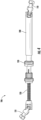
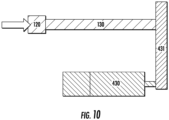
- the manually adjustable strut 106 includes an outer body 108 including a first joint 110 for coupling to a first platform, an internally threaded member or adjustment nut 120 coupled to the outer body 108, and an externally threaded rod or lead screw 130 including a second joint 131 for coupling to a second platform, the externally threaded rod 130 threadably engaging the adjustment nut 120.
- the externally threaded rod 130 is constrained such that it cannot rotate relative to the outer body 108, the adjustment nut 120 is rotatably coupled to the outer body 108 but cannot translate.
- rotation of the adjustment nut 120 causes the externally threaded rod 130 to move (e.g., translate) relative to the outer body 108 to lengthen or shorten the length of the strut 106 depending on the direction of rotation.
- the adjustment nut 120 can be manually rotated, for example, by hand or using a wrench.
- the adjustment nut 120 could be modified to include teeth into an outer diameter thereof.
- the adjustment nut 120 could be replaced with a gear or the strut 106 could be modified to include a gear coupled to the threaded rod 130.
- an interface is created for coupling the motor 430 of the detachable geared-motor assembly 400 to the strut 106.
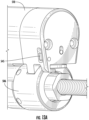
- the geared-motor assemblies 400 include a housing or enclosure 410 (terms used interchangeably herein within the intent to limit or distinguish).
- the housing 410 is arranged and configured to enclose, or at least partially enclose, all of the components of the geared-motor assembly 400.
- the geared-motor assembly 400 includes a control circuit 450 (e.g., a printed-circuit board (PCB)), a microcontroller 452, a wireless communication chip, a power supply 454 such as, for example, one or more batteries, and an optional charging circuit 456).
- the electronics and the power source being housed with the motor 430 inside the housing 410.
- the geared-motor assemblies 400 facilitate motorized and/or automated adjustment of the strut 106.
- the geared-motor assemblies 400 may be coupled (e.g., wirelessly coupled) to an external computing system running, for example, a companion APP.
- the geared-motor assemblies 400 may include an IP-68 rated housing manufactured from any suitable material including, for example, a metal or metal alloy, a polymer, a light-weight material such as PEEK, nylon, aluminum, etc.
- the housing may be manufactured via any now known or hereafter developed technique such as, for example, injection molding, additive manufacturing, etc.
- the geared-motor assembly 400 can be mounted to the manual struts 106 via a coupling mechanism 420, which can be arranged in any suitable mechanism now known or hereafter developed to couple or mount the geared-motor assemblies 400 to the struts 106 including, for example, clips, sleeves, magnets, straps, feet and spring-loaded pegs (as will be described in greater detail below), etc.
- the coupling mechanism 420 enables attachment and detachment of the geared-motor assembly 400 from the strut 106 to facilitate a change in mode between manual and automated adjustment.
- the geared-motor assembly 400 may include spring loaded arms 422 arranged and configured to enable the geared-motor assembly to clip onto or engage the outer body 108 of the strut 106.
- the outer body 108 of the strut 106 may be modified to include a flat surface and/or grooves 412 formed in the outer surface thereof.
- the modified conventional strut could be used for both manual and motorized adjustment cases.
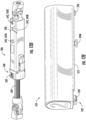
- the housing 410 of the detachable geared-motor assembly 400 may be provided in the form of an outer casing or sleeve 415.
- the outer casing or sleeve 415 includes a first housing portion 416 arranged and configured to receive the motor 430 and a second housing portion 418 arranged and configured to receive the strut 106.
- the outer casing or sleeve 415 is arranged and configured to accommodate the motor 430 and the manual strut 106 in parallel.
- the outer casing or sleeve 415 may further include a battery lid 417 and a motor lid 419.
- the threaded rod 130 of the strut 106 may extend through a threaded hole formed in the motor lid 419.
- a gasket or O-ring can be used to help seal the threaded hole thereby preventing any moisture ingress into the geared-motor assembly 400.
- the motor 430 can be any suitable motor now known or hereafter developed.
- suitable motor now known or hereafter developed.
- various example of miniature motors that can be used are provided as examples to illustrate ranges in axial thrust performance.
- the geared-motor assembly 400 includes a control circuit 450 arranged and configured as a control board or print-circuit board (PCB).
- the PCB may include a microcontroller 452, a wireless communication chip, a power supply 454 such as, for example, one or more batteries (e.g., coin cells), a charging circuit 456, and any other circuity or components needed to operate the geared-motor assemblies 400 as described herein including, for example, various surface mount devices (SMD), diodes, resistors, inductors, capacitors, etc.
- the control circuit 450 is housed within the housing 410 adjacent to and extends (or runs) substantially parallel to the motor 430 as shown in FIG. 8 .
- control circuity and/or PCB in each geared-motor assembly 400 may include one or more of the following components:
- the geared-motor assembly 400 when coupled to the strut 106, the geared-motor assembly 400 presents an offset design wherein the longitudinal axis of the motor 430 and the output shaft 434 are offset, or spaced a distance from, the longitudinal axis of the threaded rod 130 and the strut 106, as generally illustrated in FIG. 10 .
- the geared-motor assembly 400 uses a torque transferring mechanism such as, for example, interconnected first and second gears 132, 432, for transferring rotation from the motor 430 to the strut 106.
- the strut incorporating the geared-motor assembly is arranged and configured to achieve a target axial compression force of 1000N, which represents the anticipated worst case clinical loading scenario, e.g., during a stumble, walking up and down the stairs, or from asymmetrical loading across the frame.
- a target axial compression force of 1000N represents the anticipated worst case clinical loading scenario, e.g., during a stumble, walking up and down the stairs, or from asymmetrical loading across the frame.
- the motor can be isolated from any axial load it might be subjected too.
- incorporation of additional gear reduction from spur gears can provide additional protection to the "in-line" integrated gearbox. That is, for example, a secondary reduction gear could be used to protect the integrated gearbox from excessive damage due to overloading during a scheduled adjustment, which could occur during patient activity.
- adding a 3:1 gear reduction following the motor gearbox would increase the compression force resistance to 660N.
- vibration and noise based health monitoring techniques can be used to detecting anomalies in the time domain and frequency domain (e.g., using Fast Fourier Transform analysis).
- This approach may utilize acoustic emission (AE) sensors for fault detection and diagnosis.
- AE acoustic emission
- Vibration signal analysis is an important tool to experimentally investigate gear vibration because gears generate vibrations at specific frequencies, which are related to the number of gear teeth and the rotational speed of the gear shaft.
- AE signals are relatively unaffected by structural resonance and are more sensitive to early fault activities than vibrational sensors. AE emitted by very small defects occurs in frequency ranges that are higher than the operational ranges of vibration sensors and therefore might not be caught by vibration sensors. Furthermore, if there is only a small crack or surface wear in the pinion gears, it may not be severe enough to change the structural vibration. Vibration signals collected by accelerometers, which measures the second derivative of the displacement, may still remain the same, and thus be unable to detect the incipient fault.
- the geared-motor assembly 400 may include a worm-drive mechanism or transmission 700 to couple the output shaft 434 of the motor 430 to the threaded rod 130 of the strut 106.
- the output shaft 434 of the motor 430 can include, or be formed in, a worm drive 702 having, for example, a 5 mm diameter and a 1 mm pitch.
- the worm drive 702 being coupled to an intermediate shaft 710 at a first end thereof.
- the second end of the intermediate shaft 710 including a gear 712 for coupling to a gear 132 on the threaded rod 130, as will be described in greater detail below.
- a reduction ratio of 30:1 can be achieved resulting in compression force resistance of several thousand Newtons.
- the range of torque to drive a 1000N linear load would increase from 614mNm to 921mNm depending on the coefficient of friction (0.15 to 0.25). If the two contacting materials were stainless steel and aluminum then the coefficient of friction would increase to 0.6 for the static case, which would predict a torque requirement of 2000mNm for a 1000N linear load.
- Static is more relevant than dynamic because most of the time the threaded rod of the strut is non-moving and the motor will need to be able to overcome the static resistive force. This would require a reduction gear assembly of at least 13:1.
- a gear 132 such as, for example, a spur gear
- the worm-drive mechanism or transmission 700 can achieve a reduction ratio of 30:1 increasing the compression force resistance to several thousand Newtons.
- utilization of the worm-gear drive mechanism or transmission 700 to drive the spur gear that is used to engage the threaded rod 130 of the strut 106 improves the performance of the motor.
- the gear 132 coupled to the threaded rod 130 of the strut 106 and the gear 712 at the second end of the intermediate shaft 710 could be provided in the form of bevel gears, rather than spur gears (e.g., straight gears), so that the offset interface gears coupling the output shaft 434 of the motor 430 to the threaded rod 130 rotate at right-angles to the threaded rod.
- the offset interface gears can be driven by the worm-gear mechanism in preference to a standard pinion gear arrangement thus enabling a reduction of 13:1 to be achieved from the motor 430 to the gear 132 of the threaded rod 130.
- the illustrated example utilizing worm gears achieves a gear reduction ratio of 30:1 because the worm drive is driving 15 teeth, i.e., 15 revolutions of the worm drive means 1 revolution of the gear) and the beveled gears have a 2:1 ratio, which means a total reduction of 30:1.
- Utilizing a 10 mm diameter Portescap geared stepper motor can provide a torque rating of 150mNm. Therefore, this overall arrangement could comfortably support 2000mNm even allowing for efficiency losses, and deliver 1000N linear force using the existing threaded rod of the strut.
- a duty cycle from an adjustment once every minute to once every 45 seconds, which would increase the number of adjustment intervals from 1440 to 1920 adjustment intervals per day, respectively, a 33% increase in adjustment intervals could accommodate any attempt made by the software to adjust the spatial frame during very high loading periods allowing the system to skip and make adjustments at the next interval.
- This type of duty cycle would ensure that strut adjustments were only attempted when the applied forces are light, whilst still maintaining a more fractionated rhythm for bone adjustment.
- a selectively attachable and detachable geared-motor assembly 400 is disclosed.
- the struts 106 can be manually adjusted (e.g., rotated).
- the struts 106 can be manually adjusted to their necessary starting position in the operating room by a health care provider (e.g., surgeon) to facilitate initial setup and construction of the spatial frame.
- a health care provider e.g., surgeon
- the initial length of the strut 106 can be easily set up by conventional processes.
- the geared-motor assemblies 400 can be coupled to the struts 106.
- the geared-motor assemblies 400 can be coupled to each of the plurality of struts 106 in clinic to enable subsequent automated and/or motorized adjusts to the length of the struts as required by the treatment plan, although it is envisioned that the geared-motor assemblies could be coupled to the struts at any point during treatment.
- the geared-motor assemblies 400 By configuring the geared-motor assemblies 400 to be coupled to the manually adjustable struts 106 in a fracture clinic once the spatial frame has been surgically attached onto the patient, the need for sterilization of the geared-motor assemblies 400 is eliminated thereby facilitating easier assembling and maintenance of the geared-motor assemblies 400.
- an exemplary spatial frame 500 is disclosed.
- the spatial frame 500 may include first and second platforms 502, 504 and a plurality of struts 506 coupled thereto.
- each of the plurality of struts 506 is arranged and configured to receive, couple to, mate with, etc. a geared-motor assembly 510.
- the geared-motor assembly 510 may be similar in operation and configuration to the previously described geared-motor assemblies described herein except as provided for below.
- each geared-motor assembly 510 may be arranged and configured as a self-contained unit including any necessary components required for operation including, for example, powered electronics including any control circuit or printed-circuit board (PCB) 511, microprocessor, wireless communication chip(s), wireless transmitter(s), wireless receiver(s), antenna(s), power supply (e.g., one or more batteries) 515, and motor 514 such as, for example, exemplary PCB 450, microprocessor 452, power supply 454, and motor previously described herein.
- PCB printed-circuit board
- each geared-motor assembly 510 may be arranged and configured to receive instructions from, for example, a mobile device, another geared-motor assembly 510, etc. and to control (e.g., extend, retract, etc.) the strut 506 to which it is coupled based on said instructions.
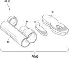
- the housing 512 of the geared-motor assembly 510 may include an opening 522 arranged and configured to enable access to the gear(s) 518, 520 associated with the motor 514.
- access to the gear 518 of the motor 514 may be provided (e.g., gear 518 or gear 520 may protrude from the housing 512 of the geared-motor assembly 510 to engage, mesh, etc. with the gear 532 of the strut 506).
- the spring-loaded projection or peg 526 extends (e.g., drops) into the third recess 542C securing the geared-motor assembly 510 in its final, locked position.
- the geared-motor assembly 510 In its final, locked position, the geared-motor assembly 510 is securely coupled to the housing 530 of the strut 506 with the gears 518, 520, 532 intermeshed.
- An optional set screw 550 FIG. 12I ) may be installed to securely lock the position of the geared-motor assembly 510 to the housing 530 of the strut 506.
- the housing 530 of the strut 506 may include a removal hole 544 arranged and configured to receive a tool.
- the tool may be inserted into the removal hole 544 and into contact with the spring-loaded projection or peg 526.
- the tool can be used to push up on the spring-loaded projection or peg 526 allowing for removal of the projection or peg 526 from the third recess 542C (e.g., allows projection or peg 526 to be pushed out of the third recess 542C against the bias of the spring) and thus allowing the geared-motor assembly 510 to be rotated relative to the housing 530 of the strut 506 and thus enabling disengagement of the geared-motor assembly 510 from the housing 530 of the strut 506.
- the geared-motor assemblies 510 and/or the strut 506 may include any other suitable mechanism to facilitate disengagement of the geared motor assemblies 510 from the strut 506. For example, with reference to FIGS.
- the geared-motor assemblies 510 may include a lever 545 arranged and configured to engage, for example, the spring loaded-peg 526 or other projection 527 extending from the strut 506.
- the user can activate the lever 545 thereby disengaging the peg 526 or other projection 527, and thus the geared-motor assembly 510 from the strut 506.
- While having a single assembly 510 as the primary assembly for communication, control, etc. functionalities may have several technical and usability advantages, it may cause a faster power source draining of the primary assembly 510's power source than power sources of secondary assemblies 510. For example, if each assembly 510 is powered by independent batteries, the primary assembly 510's battery may run out of power faster than the secondary assemblies because of the additional power consumption required for strut communication, data analysis, etc.
- each assembly 510 might not experience the same loading or any other operational conditions. For example, some assemblies 510 may have to overcome higher loads than others during adjustments. Different assemblies may also adjust more frequently and/or a further distance than others. Further, the loading conditions and/or prescribed adjustments of each assembly relative to other assemblies may change throughout the prescribed course of treatment. Such varying load conditions, prescribed adjustments, different length and/or frequency of adjustments, etc. of each assembly 510 may drain power source capacities differently for each assembly, such that some assemblies may drain their power sources faster than others.
- the current subject matter may be configured to assign, re-assign, change and/or shift assignments and/or designations of primary and/or secondary roles among geared-motor assemblies 510 in the spatial frame 500 based on various factors, schedules, thresholds, etc.
- a primary role of one assembly 510 may be transferred to another assembly 510 in the spatial frame 500 based on a determination that the current power level in the power source of the current primary assembly 510 has fallen below a predetermined threshold and thus, to avoid excessive power drainage, another assembly 510 (e.g., one with the highest current power level, least amount of load, etc.) may be selected as the new primary assembly and responsibilities of the primary assembly may be transferred to it.
- the former primary assembly will become a secondary assembly.
- Such change may occur dynamically (e.g., based on power level measurements, load measurements, etc.) and/or statically (e.g., based on a pre-programmed schedule, time spent as a primary assembly, strut replacement, etc.). Further, these changes may occur automatically and/or manually (e.g., using an application operating on an external device communicatively coupled to one or more assemblies 510, etc.).
- the above changes may be configured to ensure proper adjustment of bone segments by the spatial frame 500 as well as prevent uneven drain of power from power sources of the geared-motor assemblies 510 (as well as conserve power in the power sources).
- the spatial frame 500 may be configured to execute adjustments and/or manipulations of bone segments in accordance with a prescribed schedule and/or a prescription.
- the prescription dictates a magnitude of each adjustment, direction of each adjustment, time of each adjustment, frequency of adjustments, etc. Adjustments may be executed using a single geared-motor assembly 510 and/or any combination of assemblies 510.
- the assemblies 510 may adjust to different magnitudes, different directions, different frequencies, etc.
- the prescription may be uploaded to the spatial frame 500 wirelessly and/or using a temporary wired connection with an external device, where, for the purposes of uploading, a single assembly 510 may be selected.
- the communications with the assembly 510 may be performed using one or more of its antenna(s), wireless receiver(s), wireless transmitter(s), wireless communication chip(s) and/or any other hardware/software. Selection of a specific assembly 510 may be at random and/or may be identified in the prescription plan and/or based on assembly's power levels, current operational state, load, etc. and/or any other factors.
- the selected assembly 510 may also be designated as a primary assembly that may be used for further communications with one or more external devices as well as other assemblies 510 in the spatial frame 500, which may be designated as secondary assemblies.
- the primary assembly 510 e.g., assembly 1 as shown in FIG. 12A
- secondary assemblies 510 e.g., assemblies 2-6 as shown in FIG.
- the primary assembly may be configured to generate one or more requests (e.g., signals, queries, etc.) to the secondary assemblies to receive their respective status updates, battery life, position data, load data, etc. Further, the primary assembly may also be configured to execute its own adjustments as identified in the prescription and/or determined by the primary assembly based on at least one of the following: its own load data, load data and/or any other data received from one or more secondary assemblies, power levels, etc.
- the primary assembly may be configured to execute analysis of all data that it has received from secondary assemblies, information contained in the prescription plan and/or any other information, and generate one or more instructions for performing adjustments to all assemblies (including itself).
- the analysis may be performed dynamically, and/or based on a predetermined schedule.
- such analysis and generation of instructions may be executed by one or more external devices based on the data received from the primary assembly, where instructions may be transmitted back to the primary assembly for relaying to secondary assemblies.
- the secondary assemblies may be configured to communicate with the primary assembly only. This may include reporting any operational data, adjustment data, load data, power level data. The reporting may be executed by the secondary assemblies in accordance with a predetermined schedule and/or dynamically (e.g., based on a specific detected load, power level, etc.) and/or based on one or more requests from the primary assembly.
- the remaining functional assemblies 510 may be programmed and/or instructed to hold any further adjustments until the malfunctioning assembly is restored to its proper operational status (which may be reported to the primary assembly).
- the primary assembly 510 may be configured to inform the functioning secondary assemblies to hold adjustments if one of them becomes inoperable.
- the secondary assemblies may be configured to hold their adjustments upon detecting that the primary assembly became inoperable. Such holding of adjustments may be pre-programmed and/or determined based on detection of a malfunction of one or more assemblies.
- each assembly may be configured, in addition to storing pre-programmed instructions for addressing inoperability of one or more assemblies, to store instructions for its own adjustments and/or adjustments of other assemblies.
- one or more assemblies and/or group of assemblies may be configured to modify their prescribed adjustments (either based on appropriate instructions from the primary assembly and/or on their own) to address any changes in operation of the spatial frame 500.
- the primary and secondary roles assigned to the assemblies 510 in the spatial frame 500 may be assigned/reassigned from and/or between assemblies. Such assignment/re-assignment may be performed based on an analysis of data gathered from each assembly during operation (e.g., power level, load level, operation status, etc.), predetermined schedule (e.g., as outlined in the prescription plan), instructions from one or more external devices, and/or any other factors. The analysis and/or subsequent determination of assignment/reassignment of primary/secondary roles may be performed by the current primary assembly and/or one or more external devices and/or both.
- assignment/re-assignment of roles may be performed based on a secondary assembly requesting to do so, for example, as a result of its current operational status. As can be understood, assignment/re-assignment of roles may be performed based on any combination of factors, data, instructions, etc. and/or using any combination of assemblies and/or external devices, etc.
- one or more external devices may be configured to execute an application (e.g., a web-based application) that may be configured to generate a prescription identifying how and when each assembly 510 in the spatial frame 500 may need to execute its adjustments.
- the prescription may or may not identify a primary assembly for communication with the secondary assemblies and/or external device(s) and/or for controlling operations of all assemblies 510.
- the primary assembly may be randomly selected and/or based on data that may be available at the time of generation and/or transmission of the prescription plan to the spatial frame 500.
- the primary assembly 510 e.g., assembly 1 in FIG.
- the current primary assembly (e.g., assembly 1) may be configured to communicate with one or more secondary assembly (e.g., assembly 2) and initiate a transfer of the primary role to that assembly.
- the transfer may include extraction of various data associated with operational control of the assemblies that the current primary assembly has received (e.g., prescription plan, data received during the time that assembly was primary, etc.) and stored in its memory.
- assignment/re-assignment of primary role may be executed at a predetermined times, which may or may not occur based on a determination of whether a particular threshold associated with, for example, power source level, load, and/or any other operational data and/or any combination thereof, is reached.
- assignment/reassignment of primary role may occur independent of predetermined time once such threshold is reached (e.g., power drain threshold is reached prior to the predetermined time).
- assignment/re-assignment of the primary role may also be based on various communication parameters. For example, communication distances, antenna orientations, type of communications (e.g., BluetoothTM, WiFi, NFC, etc.), and/or any other factors may affect power level drain of a power source and thus, may be factored into the decision of whether the primary role of a particular assembly 510 may need to be assigned/re-assigned.
- communication parameters For example, communication distances, antenna orientations, type of communications (e.g., BluetoothTM, WiFi, NFC, etc.), and/or any other factors may affect power level drain of a power source and thus, may be factored into the decision of whether the primary role of a particular assembly 510 may need to be assigned/re-assigned.
- the primary assembly's battery level drops below 20%, its primary role may be assigned/re-assigned to another assembly 510 (e.g., assuming any other assembly 510 has more than 20% battery life).
- the primary role may, for example, be assigned/re-assigned to an assembly with the highest level of battery remaining.
- assignment/re-assignment of the primary role may be based on the particulars of the prescription plan and/or as outlined in the prescription plan. Operation of the spatial frame 500 (e.g., adjustments by each assembly, communications, etc.) requires current draws (e.g., from power sources of one or more assemblies, etc.) for the purposes of activating of motors, electronics, etc. Since the motions of each strut are determined by the generated prescription plan, the entire adjustment pattern of each strut may be known prior to and/or as soon as the prescription plan is generated. The primary role may be assigned to the assembly 510 that may be determined to adjust the least amount over the course of the prescription plan. This may allow to preserve as much power in that assembly's power source as possible.
- the primary role assignment/re-assignment may be based on load(s) experienced by one or more assemblies 510.
- the spatial frame 50 may be positioned in a variety of anatomic locations and/or at various orientations. The orientation of the spatial frame 500 may change during adjustment in accordance with the prescription plan. Anatomic forces acting upon the spatial frame 500 may also change during the prescription plan. As a result, assemblies 510 may not be loaded evenly. Each assembly 510 may experience different load schemes at any given time and/or the loading schemes of each assembly may change during the prescription plan. As such, the spatial frame 500 may be configured to measure and/or record current draw(s) that may be attributed to actuating each assembly 510.
- the primary role may be assigned/re-assigned to the assembly which is loaded the least at the beginning of prescription plan, the assembly which is loaded the least at a predetermined time during prescription plan, and/or at any other time, and/or any combination thereof.
- assignment/re-assignment of primary role among assemblies 510 may be dependent on time (e.g., time intervals) to allow for managing of power drain on the primary assembly's power source.
- time e.g., time intervals
- one or more assemblies 510 and/or one or more external devices may be programmed to assign/re-assign the primary role once during a particular time interval (e.g., hour, day, week, month, etc.).
- the current subject matter may be configured to check the power levels of all power sources of assemblies 510 and assign/re-assign the primary role to the assembly that has the most power remaining in its power source.
- the primary role may also be assigned/reassigned after a predetermined number of adjustment cycles executed by the spatial frame 500 (as a whole) and/or one or more assemblies 510.
- the primary assembly may be determined by the external device with which the external device may communicate. For some patients, e.g., pediatric patients, they may not be near the paired external device for hours at a time and as such, primary role may be assigned/re-assigned at the time of reconnection with the external device.
- the current subject matter may be configured to reduce a burden of using an automated spatial frame for both surgeons and patients by absolving a need for a large non-rechargeable battery, which is cumbersome, heavy, interferes with fixation, and is difficult to replace.
- the current subject matter provides an easy and efficient way of managing and optimizing battery life to allow for a complete treatment for patients without a need for a battery change.
- the geared-motor assemblies eliminate the need for sterilization and offer a quick and simple method for implementing motorized and/or automated adjustment capability in a treatment plan.
- a companion APP can be used to transmit and receive commands and updates for the detachable geared-motor assemblies.
- the companion APP can be configured to scan for beacons at set time intervals and establish connections with one or more of the geared-motor assemblies depending on whether a primary/secondary communication scheme is implemented. The connections enabling the receipt and/or transmission of data, updates, etc.
- the companion APP can be programmed to track a patient's treatment plan in terms of (a) force-feedback, (b) date and time of distraction, (c) lengthening schedule/direction, (d) rate (mm/day) and rhythm (steps/day) of distraction, (e) distraction length and (f) potential adverse events/complications.
- Connection references are to be construed broadly and may include intermediate members between a collection of elements and relative to movement between elements unless otherwise indicated. As such, connection references do not necessarily infer that two elements are directly connected and in fixed relation to each other. All rotational references describe relative movement between the various elements. Identification references (e.g., primary, secondary, first, second, third, fourth, etc.) are not intended to connote importance or priority but are used to distinguish one feature from another.
- the drawings are for purposes of illustration only and the dimensions, positions, order and relative to sizes reflected in the drawings attached hereto may vary.
Landscapes
- Health & Medical Sciences (AREA)
- Orthopedic Medicine & Surgery (AREA)
- Life Sciences & Earth Sciences (AREA)
- Surgery (AREA)
- Medical Informatics (AREA)
- General Health & Medical Sciences (AREA)
- Biomedical Technology (AREA)
- Heart & Thoracic Surgery (AREA)
- Nuclear Medicine, Radiotherapy & Molecular Imaging (AREA)
- Molecular Biology (AREA)
- Animal Behavior & Ethology (AREA)
- Engineering & Computer Science (AREA)
- Public Health (AREA)
- Veterinary Medicine (AREA)
- Neurosurgery (AREA)
- Oral & Maxillofacial Surgery (AREA)
- Pathology (AREA)
- Accommodation For Nursing Or Treatment Tables (AREA)
- Connection Of Motors, Electrical Generators, Mechanical Devices, And The Like (AREA)
Claims (15)
- Orthopädischer räumlicher Rahmen (100, 300, 500), umfassend:eine erste Plattform (102);eine zweite Plattform (104), die von der ersten Plattform beabstandet ist;eine Vielzahl von in der Länge anpassbaren Streben (106), wobei jede der Vielzahl von in der Länge anpassbaren Streben mit der ersten Plattform und der zweiten Plattform gekoppelt ist, wobei jede der in der Länge anpassbaren Streben ein Gehäuse (108, 202, 530) und eine Gewindestange (130, 224, 534) aufweist, wobei die Gewindestange dazu angeordnet und ausgelegt ist, sich bezogen auf das Gehäuse zu bewegen, um eine Länge der Strebe anzupassen; undeine Vielzahl von Getriebemotoranordnungen (400, 510), wobei jede der Vielzahl von Getriebemotoranordnungen dazu angeordnet und ausgelegt ist, mit einer der Vielzahl von in der Länge anpassbaren Streben zu koppeln, wobei jede der Vielzahl von Getriebemotoranordnungen als eine eigenständige Einheit angeordnet und ausgelegt ist, die Elektronik und Stromversorgung aufweist, um (i) drahtlos mit einer externen Rechenvorrichtung zu kommunizieren und (ii) die Länge der Strebe, an die sie gekoppelt ist, anzupassen.
- Orthopädischer räumlicher Rahmen nach Anspruch 1, wobei jede der Vielzahl von Getriebemotoranordnungen von jeglichen externen Drähten zum Koppeln mit einer externen Steuerung frei ist.
- Orthopädischer räumlicher Rahmen nach einem der vorhergehenden Ansprüche, wobei jede der Getriebemotoranordnungen aufweist:ein Gehäuse (410, 512);einen Motor, der eine Ausgangswelle (434, 516) und ein Zahnrad (518) aufweist;eine Leiterplatte (450, 511), die einen Mikroprozessor (452) und einen Chip für die drahtlose Kommunikation aufweist; undeine Stromversorgung (454, 515), die dazu angeordnet und ausgelegt ist, Strom für den Motor und die Leiterplatte bereitzustellen.
- Orthopädischer räumlicher Rahmen nach einem der vorhergehenden Ansprüche, wobei eine der Vielzahl von Getriebemotoranordnungen als Primäranordnung (510) ausgelegt ist, die dazu angeordnet und ausgelegt ist, mit einer externen Recheneinrichtung zu kommunizieren, um Anweisungen zu empfangen und Anweisungen an die übrigen Sekundäranordnungen zu übermitteln.
- Orthopädischer räumlicher Rahmen nach Anspruch 4, wobei die Primäranordnung wahlweise derart austauschbar ist, dass die mit der Primäranordnung verknüpften Aufgaben an eine der Sekundäranordnungen übertragen werden können.
- Orthopädischer räumlicher Rahmen nach Anspruch 5, wobei die mit der Primäranordnung verknüpften Aufgaben basierend auf einem oder mehreren der folgenden Punkte an eine der Sekundäranordnungen übertragen werden:verbleibende Stromversorgung der Primäranordnung;wenn der Pegel einer verbleibenden Stromversorgung der Primäranordnung unter einem Schwellenwert liegt;ein vorbestimmter Zeitplan;eine vorbestimmte Zeit;in Übereinstimmung mit einem Verordnungsplan, der für den räumlichen Rahmen bestimmt wurde;eine Anweisung, die von einer oder mehreren externen Einrichtungen empfangen wurde, die kommunikativ mit mindestens einer von der Primäranordnung und mindestens einer Sekundäranordnung gekoppelt ist.
- Orthopädischer räumlicher Rahmen nach Anspruch 5, wobei die mit der Primäranordnung verknüpften Aufgaben basierend zumindest auf Daten, die von der Primäranordnung von mindestens einer Sekundäranordnung empfangen wurden, an eine der Sekundäranordnungen übertragen werden,
wobei die Daten mindestens eines der Folgenden aufweisen: einen Stromversorgungspegel der mindestens einen Sekundäranordnung, einen Lastpegel der mindestens einen Sekundäranordnung, eine Frequenz der Anpassungen, die von der mindestens einen Sekundäranordnung durchgeführt wurden, eine Länge der Anpassungen, die von der mindestens einen Sekundäranordnung durchgeführt wurden, eine oder mehrere Positionierungskoordinaten der mindestens einen Sekundäranordnung, einen Winkel der Anpassungen, die von der mindestens einen Sekundäranordnung durchgeführt wurden, eine Richtung der Anpassungen der mindestens einen Sekundäranordnung und jede Kombination davon. - Orthopädischer räumlicher Rahmen nach Anspruch 5, wobei die mit der Primäranordnung verknüpften Aufgaben an eine der Sekundäranordnungen übertragen werden basierend auf mindestens einem von: Lastdaten der Primäranordnung, Lastdaten von mindestens einer Sekundäranordnung, einem Stromversorgungspegel der Primäranordnung, einem Stromversorgungspegel der mindestens einen Sekundäranordnung und jede Kombination davon.
- Orthopädischer räumlicher Rahmen nach Anspruch 1, wobei jede der Vielzahl von Streben ein Zahnrad (132, 532) aufweist, das mit der Gewindestange gekoppelt ist; undjede der Vielzahl von Getriebemotoranordnungen ein Gehäuse (410, 512), einen Motor mit einer Ausgangswelle (434, 516) und ein damit verbundenes Zahnrad (432) aufweist, wobei das Zahnrad des Motors dazu angeordnet und ausgelegt ist, funktional mit dem Zahnrad der Strebe gekoppelt zu werden,wobei jede der Getriebemotoranordnungen ferner eins oder mehrere Zwischenräder (520) aufweist, die dazu angeordnet und ausgelegt sind, das Zahnrad des Motors und das Zahnrad der Strebe in Eingriff zu nehmen.
- Orthopädischer räumlicher Rahmen nach Anspruch 9, wobei das Zahnrad der Strebe mindestens teilweise in dem Gehäuse der Strebe enthalten ist, wobei das Gehäuse der Strebe eine Öffnung zum Bereitstellen von Zugang zu dem Zahnrad (540) aufweist, und das Gehäuse der Getriebemotoranordnung eine Öffnung (522) aufweist, um zu ermöglichen, dass sich eins von dem Zahnrad des Motors und eins von dem einen oder den mehreren Zwischenzahnrädern dort hindurch erstreckt.
- Orthopädischer räumlicher Rahmen nach Anspruch 10, wobei das Gehäuse der Strebe ferner eine erste Aussparung (542A) und eine Stiftaussparung aufweist; unddas Gehäuse der Getriebemotoranordnung einen ersten Vorsprung (524A) und einen federbelasteten Stift (526) aufweist, der sich von einer Oberfläche davon erstreckt, die erste Aussparung, die in dem Gehäuse der Strebe gebildet ist, dazu angeordnet und ausgelegt ist, den ersten Vorsprung der Getriebemotoranordnung aufzunehmen, wobei durch den ersten in der ersten Aussparung aufgenommen Vorsprung die Getriebemotoranordnung bezogen auf die Strebe gedreht werden kann,wobei die Drehung der Getriebemotoranordnung bezogen auf die Strebe bewirkt, dass der federbelastete Stift der Getriebemotoranordnung in der Stiftaussparung aufgenommen wird.
- Orthopädischer räumlicher Rahmen nach Anspruch 11, wobei die Drehung der Getriebemotoranordnung bezogen auf die Strebe bewirkt, dass der federbelastete Stift eine an dem Gehäuse der Strebe gebildete Rampe kontaktiert, um den federbelasteten Stift zu komprimieren, bis der federbelastete Stift auf die Stiftaussparung ausgerichtet ist.
- Orthopädischer räumlicher Rahmen nach Anspruch 11, wobei das Gehäuse der Strebe ferner eine zweite Aussparung (542B) aufweist; und
das Gehäuse der Getriebemotoranordnung einen zweiten Vorsprung (524B) aufweist, der sich von einer Oberfläche davon erstreckt, wobei die zweite Aussparung, die in dem Gehäuse der Strebe gebildet ist, dazu angeordnet und ausgelegt ist, den zweiten Vorsprung der Getriebemotoranordnung aufzunehmen. - Orthopädischer räumlicher Rahmen nach Anspruch 13, wobei die Drehung der Getriebemotoranordnung bezogen auf die Strebe bewirkt, dass der zweite Vorsprung in der zweiten Aussparung aufgenommen wird.
- Orthopädischer räumlicher Rahmen nach Anspruch 11, wobei das Gehäuse der Strebe ferner ein Entnahmeloch (544) in Verbindung mit der Stiftaussparung aufweist, so dass ein Werkzeug eingeführt werden kann, um die Entnahme des federbelasteten Stifts aus der Stiftaussparung zu erleichtern, um zu ermöglichen, die Getriebemotoranordnung von der Strebe zu lösen.
Applications Claiming Priority (2)
| Application Number | Priority Date | Filing Date | Title |
|---|---|---|---|
| US202263312760P | 2022-02-22 | 2022-02-22 | |
| PCT/US2023/013011 WO2023163874A1 (en) | 2022-02-22 | 2023-02-14 | Detachable geared-motor assembly for motorizing a strut in a spatial frame |
Publications (2)
| Publication Number | Publication Date |
|---|---|
| EP4482409A1 EP4482409A1 (de) | 2025-01-01 |
| EP4482409B1 true EP4482409B1 (de) | 2025-04-16 |
Family
ID=86054061
Family Applications (1)
| Application Number | Title | Priority Date | Filing Date |
|---|---|---|---|
| EP23718398.3A Active EP4482409B1 (de) | 2022-02-22 | 2023-02-14 | Abnehmbare getriebemotoranordnung zur motorisierung einer strebe in einem räumlichen rahmen |
Country Status (3)
| Country | Link |
|---|---|
| US (1) | US20250177005A1 (de) |
| EP (1) | EP4482409B1 (de) |
| WO (1) | WO2023163874A1 (de) |
Families Citing this family (5)
| Publication number | Priority date | Publication date | Assignee | Title |
|---|---|---|---|---|
| EP4615350A1 (de) * | 2022-11-10 | 2025-09-17 | Smith & Nephew, Inc. | Motorrückkopplung eines motorisierten federbeinmotors |
| WO2024102395A1 (en) * | 2022-11-10 | 2024-05-16 | Smith & Nephew, Inc. | Motorized strut wireless communication |
| ES3038870T3 (en) * | 2022-12-23 | 2025-10-15 | Orthofix Srl | Tool for external fixation strut adjustment |
| EP4389030B1 (de) * | 2022-12-23 | 2025-07-23 | Orthofix S.r.l. | Werkzeug zur externen fixationsstrebeneinstellung, verstellbare externe fixationsstrebe und kit mit der fixationsstrebe und dem werkzeug |
| EP4694807A1 (de) | 2023-04-14 | 2026-02-18 | Smith&Nephew, Inc. | Motormodul zur motorisierung einer strebe in einem räumlichen rahmen |
Family Cites Families (13)
| Publication number | Priority date | Publication date | Assignee | Title |
|---|---|---|---|---|
| US5728095A (en) | 1995-03-01 | 1998-03-17 | Smith & Nephew, Inc. | Method of using an orthopaedic fixation device |
| NZ303050A (en) | 1995-03-01 | 1998-05-27 | Smith & Nephew Inc | Spatial frame with a first element positionable relative to a second element |
| US5971984A (en) | 1995-03-01 | 1999-10-26 | Smith & Nephew, Inc. | Method of using an orthopaedic fixation device |
| US5891143A (en) | 1997-10-20 | 1999-04-06 | Smith & Nephew, Inc. | Orthopaedic fixation plate |
| US6030386A (en) | 1998-08-10 | 2000-02-29 | Smith & Nephew, Inc. | Six axis external fixator strut |
| US6129727A (en) | 1999-03-02 | 2000-10-10 | Smith & Nephew | Orthopaedic spatial frame apparatus |
| US20020010465A1 (en) * | 2000-01-31 | 2002-01-24 | Ja Kyo Koo | Frame fixator and operation system thereof |
| DE10151754B4 (de) * | 2001-10-19 | 2005-01-20 | Klaus Priv.-Doz. Dr. med. Seide | Längeneinstellelement |
| JP2005537818A (ja) | 2002-04-05 | 2005-12-15 | スミス アンド ネフュー インコーポレーテッド | 整形外科用固定方法と装置 |
| US8864750B2 (en) * | 2008-02-18 | 2014-10-21 | Texas Scottish Rite Hospital For Children | Tool and method for external fixation strut adjustment |
| RU2015152862A (ru) | 2013-05-14 | 2017-06-19 | Смит Энд Нефью, Инк. | Устройство и способ управления предписанием для медицинского устройства |
| EP4034009B1 (de) | 2019-09-26 | 2024-07-10 | Smith & Nephew, Inc. | Automatischer räumlicher rahmen und damit verwendete automatische streben |
| IL300186A (en) * | 2020-07-30 | 2023-03-01 | Synthes Gmbh | Detachable engine |
-
2023
- 2023-02-14 EP EP23718398.3A patent/EP4482409B1/de active Active
- 2023-02-14 WO PCT/US2023/013011 patent/WO2023163874A1/en not_active Ceased
- 2023-02-14 US US18/839,091 patent/US20250177005A1/en active Pending
Also Published As
| Publication number | Publication date |
|---|---|
| EP4482409A1 (de) | 2025-01-01 |
| US20250177005A1 (en) | 2025-06-05 |
| WO2023163874A1 (en) | 2023-08-31 |
Similar Documents
| Publication | Publication Date | Title |
|---|---|---|
| EP4482409B1 (de) | Abnehmbare getriebemotoranordnung zur motorisierung einer strebe in einem räumlichen rahmen | |
| US12471955B2 (en) | Automated spatial frame and automated struts used therewith | |
| US20220346840A1 (en) | Craniofacial external distraction apparatus | |
| JP7693983B2 (ja) | 着脱式モータ | |
| AU2024203541A1 (en) | Orthosis or Exoskeleton System with Modular Elements | |
| KR20150127802A (ko) | 모션제어 수술대 | |
| US12396767B2 (en) | Implantable motorized bone adjustment devices | |
| US12402916B2 (en) | Connection mechanisms for coupling printed circuit board modules to a ring in an automated and/or motorized spatial frame | |
| EP4694807A1 (de) | Motormodul zur motorisierung einer strebe in einem räumlichen rahmen | |
| JP6713689B2 (ja) | 体内埋め込み型動作アシスト装置および体内埋め込み型歩行アシスト装置 | |
| WO2023048948A1 (en) | Quick adjustment mechanism for a motorized strut in a spatial frame | |
| WO2023141032A1 (en) | Motorized strut for use in a motorized spatial frame | |
| EP4615350A1 (de) | Motorrückkopplung eines motorisierten federbeinmotors | |
| JP2005204987A (ja) | 骨自動延長器 | |
| US20230210566A1 (en) | Systems and processes for distraction control | |
| EP4539758A1 (de) | Programmiergerät zur verwendung in einem motorisierten räumlichen rahmen | |
| US20260053535A1 (en) | Intermedullary lengthening implant with integrated load sensor | |
| CN119548225B (zh) | 一种芯片远程控制的骨牵张成骨系统 | |
| EP4615351A1 (de) | Drahtloskommunikation mit motorisierter strebe | |
| WO2026046801A1 (en) | Strut adjustment in a motorized bone fixation device | |
| CN115501013A (zh) | 一种高度自适应调节的旋转成形术术后假肢系统 | |
| Cherepanska et al. | AUTOMATED SYSTEM FOR THE COLLECTION, PROCESSING AND TRANSMISSION OF MEDICAL INFORMATION BY OBSERVING OF PATIENTS WITH AFFECTED LOWER LIMBS | |
| Gamage | Elbow exercise assistant | |
| WO2018204280A1 (en) | Active assist orthotic |
Legal Events
| Date | Code | Title | Description |
|---|---|---|---|
| STAA | Information on the status of an ep patent application or granted ep patent |
Free format text: STATUS: UNKNOWN |
|
| STAA | Information on the status of an ep patent application or granted ep patent |
Free format text: STATUS: THE INTERNATIONAL PUBLICATION HAS BEEN MADE |
|
| GRAP | Despatch of communication of intention to grant a patent |
Free format text: ORIGINAL CODE: EPIDOSNIGR1 |
|
| STAA | Information on the status of an ep patent application or granted ep patent |
Free format text: STATUS: GRANT OF PATENT IS INTENDED |
|
| PUAI | Public reference made under article 153(3) epc to a published international application that has entered the european phase |
Free format text: ORIGINAL CODE: 0009012 |
|
| 17P | Request for examination filed |
Effective date: 20240923 |
|
| AK | Designated contracting states |
Kind code of ref document: A1 Designated state(s): AL AT BE BG CH CY CZ DE DK EE ES FI FR GB GR HR HU IE IS IT LI LT LU LV MC ME MK MT NL NO PL PT RO RS SE SI SK SM TR |
|
| P01 | Opt-out of the competence of the unified patent court (upc) registered |
Free format text: CASE NUMBER: APP_1491/2025 Effective date: 20250110 |
|
| GRAS | Grant fee paid |
Free format text: ORIGINAL CODE: EPIDOSNIGR3 |
|
| GRAA | (expected) grant |
Free format text: ORIGINAL CODE: 0009210 |
|
| STAA | Information on the status of an ep patent application or granted ep patent |
Free format text: STATUS: THE PATENT HAS BEEN GRANTED |
|
| AK | Designated contracting states |
Kind code of ref document: B1 Designated state(s): AL AT BE BG CH CY CZ DE DK EE ES FI FR GB GR HR HU IE IS IT LI LT LU LV MC ME MK MT NL NO PL PT RO RS SE SI SK SM TR |
|
| REG | Reference to a national code |
Ref country code: GB Ref legal event code: FG4D |
|
| REG | Reference to a national code |
Ref country code: CH Ref legal event code: EP Ref country code: DE Ref legal event code: R096 Ref document number: 602023002979 Country of ref document: DE |
|
| REG | Reference to a national code |
Ref country code: IE Ref legal event code: FG4D |
|
| REG | Reference to a national code |
Ref country code: NL Ref legal event code: MP Effective date: 20250416 |
|
| PG25 | Lapsed in a contracting state [announced via postgrant information from national office to epo] |
Ref country code: NL Free format text: LAPSE BECAUSE OF FAILURE TO SUBMIT A TRANSLATION OF THE DESCRIPTION OR TO PAY THE FEE WITHIN THE PRESCRIBED TIME-LIMIT Effective date: 20250416 |
|
| REG | Reference to a national code |
Ref country code: AT Ref legal event code: MK05 Ref document number: 1785000 Country of ref document: AT Kind code of ref document: T Effective date: 20250416 |
|
| PG25 | Lapsed in a contracting state [announced via postgrant information from national office to epo] |
Ref country code: FI Free format text: LAPSE BECAUSE OF FAILURE TO SUBMIT A TRANSLATION OF THE DESCRIPTION OR TO PAY THE FEE WITHIN THE PRESCRIBED TIME-LIMIT Effective date: 20250416 Ref country code: ES Free format text: LAPSE BECAUSE OF FAILURE TO SUBMIT A TRANSLATION OF THE DESCRIPTION OR TO PAY THE FEE WITHIN THE PRESCRIBED TIME-LIMIT Effective date: 20250416 Ref country code: PT Free format text: LAPSE BECAUSE OF FAILURE TO SUBMIT A TRANSLATION OF THE DESCRIPTION OR TO PAY THE FEE WITHIN THE PRESCRIBED TIME-LIMIT Effective date: 20250818 |
|
| REG | Reference to a national code |
Ref country code: LT Ref legal event code: MG9D |
|
| PG25 | Lapsed in a contracting state [announced via postgrant information from national office to epo] |
Ref country code: NO Free format text: LAPSE BECAUSE OF FAILURE TO SUBMIT A TRANSLATION OF THE DESCRIPTION OR TO PAY THE FEE WITHIN THE PRESCRIBED TIME-LIMIT Effective date: 20250716 Ref country code: GR Free format text: LAPSE BECAUSE OF FAILURE TO SUBMIT A TRANSLATION OF THE DESCRIPTION OR TO PAY THE FEE WITHIN THE PRESCRIBED TIME-LIMIT Effective date: 20250717 |
|
| PG25 | Lapsed in a contracting state [announced via postgrant information from national office to epo] |
Ref country code: PL Free format text: LAPSE BECAUSE OF FAILURE TO SUBMIT A TRANSLATION OF THE DESCRIPTION OR TO PAY THE FEE WITHIN THE PRESCRIBED TIME-LIMIT Effective date: 20250416 |
|
| PG25 | Lapsed in a contracting state [announced via postgrant information from national office to epo] |
Ref country code: BG Free format text: LAPSE BECAUSE OF FAILURE TO SUBMIT A TRANSLATION OF THE DESCRIPTION OR TO PAY THE FEE WITHIN THE PRESCRIBED TIME-LIMIT Effective date: 20250416 |
|
| PG25 | Lapsed in a contracting state [announced via postgrant information from national office to epo] |
Ref country code: HR Free format text: LAPSE BECAUSE OF FAILURE TO SUBMIT A TRANSLATION OF THE DESCRIPTION OR TO PAY THE FEE WITHIN THE PRESCRIBED TIME-LIMIT Effective date: 20250416 |
|
| PG25 | Lapsed in a contracting state [announced via postgrant information from national office to epo] |
Ref country code: AT Free format text: LAPSE BECAUSE OF FAILURE TO SUBMIT A TRANSLATION OF THE DESCRIPTION OR TO PAY THE FEE WITHIN THE PRESCRIBED TIME-LIMIT Effective date: 20250416 |
|
| PG25 | Lapsed in a contracting state [announced via postgrant information from national office to epo] |
Ref country code: RS Free format text: LAPSE BECAUSE OF FAILURE TO SUBMIT A TRANSLATION OF THE DESCRIPTION OR TO PAY THE FEE WITHIN THE PRESCRIBED TIME-LIMIT Effective date: 20250716 |
|
| PG25 | Lapsed in a contracting state [announced via postgrant information from national office to epo] |
Ref country code: IS Free format text: LAPSE BECAUSE OF FAILURE TO SUBMIT A TRANSLATION OF THE DESCRIPTION OR TO PAY THE FEE WITHIN THE PRESCRIBED TIME-LIMIT Effective date: 20250816 |
|
| PG25 | Lapsed in a contracting state [announced via postgrant information from national office to epo] |
Ref country code: LV Free format text: LAPSE BECAUSE OF FAILURE TO SUBMIT A TRANSLATION OF THE DESCRIPTION OR TO PAY THE FEE WITHIN THE PRESCRIBED TIME-LIMIT Effective date: 20250416 |
|
| PG25 | Lapsed in a contracting state [announced via postgrant information from national office to epo] |
Ref country code: SM Free format text: LAPSE BECAUSE OF FAILURE TO SUBMIT A TRANSLATION OF THE DESCRIPTION OR TO PAY THE FEE WITHIN THE PRESCRIBED TIME-LIMIT Effective date: 20250416 Ref country code: DK Free format text: LAPSE BECAUSE OF FAILURE TO SUBMIT A TRANSLATION OF THE DESCRIPTION OR TO PAY THE FEE WITHIN THE PRESCRIBED TIME-LIMIT Effective date: 20250416 |
|
| PGFP | Annual fee paid to national office [announced via postgrant information from national office to epo] |
Ref country code: FR Payment date: 20251222 Year of fee payment: 4 |
|
| REG | Reference to a national code |
Ref country code: DE Ref legal event code: R097 Ref document number: 602023002979 Country of ref document: DE |
|
| PG25 | Lapsed in a contracting state [announced via postgrant information from national office to epo] |
Ref country code: CZ Free format text: LAPSE BECAUSE OF FAILURE TO SUBMIT A TRANSLATION OF THE DESCRIPTION OR TO PAY THE FEE WITHIN THE PRESCRIBED TIME-LIMIT Effective date: 20250416 |
|
| PG25 | Lapsed in a contracting state [announced via postgrant information from national office to epo] |
Ref country code: EE Free format text: LAPSE BECAUSE OF FAILURE TO SUBMIT A TRANSLATION OF THE DESCRIPTION OR TO PAY THE FEE WITHIN THE PRESCRIBED TIME-LIMIT Effective date: 20250416 |
|
| PG25 | Lapsed in a contracting state [announced via postgrant information from national office to epo] |
Ref country code: SK Free format text: LAPSE BECAUSE OF FAILURE TO SUBMIT A TRANSLATION OF THE DESCRIPTION OR TO PAY THE FEE WITHIN THE PRESCRIBED TIME-LIMIT Effective date: 20250416 |
|
| PG25 | Lapsed in a contracting state [announced via postgrant information from national office to epo] |
Ref country code: IT Free format text: LAPSE BECAUSE OF FAILURE TO SUBMIT A TRANSLATION OF THE DESCRIPTION OR TO PAY THE FEE WITHIN THE PRESCRIBED TIME-LIMIT Effective date: 20250416 |
|
| PLBE | No opposition filed within time limit |
Free format text: ORIGINAL CODE: 0009261 |
|
| STAA | Information on the status of an ep patent application or granted ep patent |
Free format text: STATUS: NO OPPOSITION FILED WITHIN TIME LIMIT |
|
| REG | Reference to a national code |
Ref country code: CH Ref legal event code: L10 Free format text: ST27 STATUS EVENT CODE: U-0-0-L10-L00 (AS PROVIDED BY THE NATIONAL OFFICE) Effective date: 20260225 |
|
| 26N | No opposition filed |
Effective date: 20260119 |