EP4482259A1 - Plasma processing apparatus - Google Patents
Plasma processing apparatus Download PDFInfo
- Publication number
- EP4482259A1 EP4482259A1 EP24182491.1A EP24182491A EP4482259A1 EP 4482259 A1 EP4482259 A1 EP 4482259A1 EP 24182491 A EP24182491 A EP 24182491A EP 4482259 A1 EP4482259 A1 EP 4482259A1
- Authority
- EP
- European Patent Office
- Prior art keywords
- electrode
- insulating member
- holder
- processing apparatus
- plasma processing
- Prior art date
- Legal status (The legal status is an assumption and is not a legal conclusion. Google has not performed a legal analysis and makes no representation as to the accuracy of the status listed.)
- Pending
Links
- 238000000034 method Methods 0.000 claims abstract description 22
- 239000007789 gas Substances 0.000 description 27
- XKRFYHLGVUSROY-UHFFFAOYSA-N Argon Chemical compound [Ar] XKRFYHLGVUSROY-UHFFFAOYSA-N 0.000 description 2
- 230000004048 modification Effects 0.000 description 2
- 238000012986 modification Methods 0.000 description 2
- RYGMFSIKBFXOCR-UHFFFAOYSA-N Copper Chemical compound [Cu] RYGMFSIKBFXOCR-UHFFFAOYSA-N 0.000 description 1
- 229910052786 argon Inorganic materials 0.000 description 1
- 229910052802 copper Inorganic materials 0.000 description 1
- 239000010949 copper Substances 0.000 description 1
- WFKWXMTUELFFGS-UHFFFAOYSA-N tungsten Chemical compound [W] WFKWXMTUELFFGS-UHFFFAOYSA-N 0.000 description 1
- 229910052721 tungsten Inorganic materials 0.000 description 1
- 239000010937 tungsten Substances 0.000 description 1
Images


Classifications
-
- H—ELECTRICITY
- H05—ELECTRIC TECHNIQUES NOT OTHERWISE PROVIDED FOR
- H05H—PLASMA TECHNIQUE; PRODUCTION OF ACCELERATED ELECTRICALLY-CHARGED PARTICLES OR OF NEUTRONS; PRODUCTION OR ACCELERATION OF NEUTRAL MOLECULAR OR ATOMIC BEAMS
- H05H1/00—Generating plasma; Handling plasma
- H05H1/24—Generating plasma
- H05H1/48—Generating plasma using an arc
-
- H—ELECTRICITY
- H01—ELECTRIC ELEMENTS
- H01J—ELECTRIC DISCHARGE TUBES OR DISCHARGE LAMPS
- H01J37/00—Discharge tubes with provision for introducing objects or material to be exposed to the discharge, e.g. for the purpose of examination or processing thereof
- H01J37/32—Gas-filled discharge tubes
- H01J37/32431—Constructional details of the reactor
- H01J37/32532—Electrodes
- H01J37/32568—Relative arrangement or disposition of electrodes; moving means
-
- H—ELECTRICITY
- H05—ELECTRIC TECHNIQUES NOT OTHERWISE PROVIDED FOR
- H05H—PLASMA TECHNIQUE; PRODUCTION OF ACCELERATED ELECTRICALLY-CHARGED PARTICLES OR OF NEUTRONS; PRODUCTION OR ACCELERATION OF NEUTRAL MOLECULAR OR ATOMIC BEAMS
- H05H1/00—Generating plasma; Handling plasma
- H05H1/24—Generating plasma
-
- H—ELECTRICITY
- H01—ELECTRIC ELEMENTS
- H01J—ELECTRIC DISCHARGE TUBES OR DISCHARGE LAMPS
- H01J37/00—Discharge tubes with provision for introducing objects or material to be exposed to the discharge, e.g. for the purpose of examination or processing thereof
- H01J37/32—Gas-filled discharge tubes
- H01J37/32431—Constructional details of the reactor
- H01J37/3244—Gas supply means
-
- H—ELECTRICITY
- H05—ELECTRIC TECHNIQUES NOT OTHERWISE PROVIDED FOR
- H05H—PLASMA TECHNIQUE; PRODUCTION OF ACCELERATED ELECTRICALLY-CHARGED PARTICLES OR OF NEUTRONS; PRODUCTION OR ACCELERATION OF NEUTRAL MOLECULAR OR ATOMIC BEAMS
- H05H1/00—Generating plasma; Handling plasma
- H05H1/24—Generating plasma
- H05H1/26—Plasma torches
- H05H1/32—Plasma torches using an arc
- H05H1/34—Details, e.g. electrodes, nozzles
- H05H1/3447—Rod-like cathodes
-
- H—ELECTRICITY
- H05—ELECTRIC TECHNIQUES NOT OTHERWISE PROVIDED FOR
- H05H—PLASMA TECHNIQUE; PRODUCTION OF ACCELERATED ELECTRICALLY-CHARGED PARTICLES OR OF NEUTRONS; PRODUCTION OR ACCELERATION OF NEUTRAL MOLECULAR OR ATOMIC BEAMS
- H05H1/00—Generating plasma; Handling plasma
- H05H1/24—Generating plasma
- H05H1/26—Plasma torches
- H05H1/32—Plasma torches using an arc
- H05H1/34—Details, e.g. electrodes, nozzles
- H05H1/3468—Vortex generators
-
- H—ELECTRICITY
- H05—ELECTRIC TECHNIQUES NOT OTHERWISE PROVIDED FOR
- H05H—PLASMA TECHNIQUE; PRODUCTION OF ACCELERATED ELECTRICALLY-CHARGED PARTICLES OR OF NEUTRONS; PRODUCTION OR ACCELERATION OF NEUTRAL MOLECULAR OR ATOMIC BEAMS
- H05H1/00—Generating plasma; Handling plasma
- H05H1/24—Generating plasma
- H05H1/26—Plasma torches
- H05H1/32—Plasma torches using an arc
- H05H1/34—Details, e.g. electrodes, nozzles
- H05H1/3478—Geometrical details
-
- H—ELECTRICITY
- H05—ELECTRIC TECHNIQUES NOT OTHERWISE PROVIDED FOR
- H05H—PLASMA TECHNIQUE; PRODUCTION OF ACCELERATED ELECTRICALLY-CHARGED PARTICLES OR OF NEUTRONS; PRODUCTION OR ACCELERATION OF NEUTRAL MOLECULAR OR ATOMIC BEAMS
- H05H1/00—Generating plasma; Handling plasma
- H05H1/24—Generating plasma
- H05H1/26—Plasma torches
- H05H1/32—Plasma torches using an arc
- H05H1/34—Details, e.g. electrodes, nozzles
- H05H1/38—Guiding or centering of electrodes
Definitions
- the present disclosure relates to a plasma processing apparatus.
- a plasma torch capable of causing a process gas to swirl is known, as is found in Japanese Utility Model Laying-Open No. 6-54471 , for example.
- a fin member is in contact with an electrode and a nozzle. Therefore, the fin member may suffer damage due to heat from the electrode and the nozzle.
- An object of the present disclosure is to provide a plasma processing apparatus capable of reducing damage to a fin member.
- a plasma processing apparatus includes: an inner electrode that receives application of a voltage; an electrode holder that holds the inner electrode; an outer electrode formed in a tubular shape, the outer electrode surrounding the inner electrode and the electrode holder; an insulating member arranged between the inner electrode and the outer electrode and between the electrode holder and the outer electrode, the insulating member surrounding the inner electrode and the electrode holder; a fin member for forming a swirling flow around the inner electrode by causing a process gas supplied to an inner side of the insulating member to swirl; and a nozzle that blows the swirling flow converted into a plasma state, wherein the insulating member is directly or indirectly secured to the outer electrode, and the fin member is secured to the electrode holder while being spaced from the inner electrode, and is in contact with an inner circumferential surface of the insulating member.
- Fig. 1 is a cross-sectional perspective view of a plasma processing apparatus in one embodiment of the present disclosure.
- This plasma processing apparatus 1 is suitably used for surface modification of a workpiece.
- plasma processing apparatus 1 includes an inner electrode 100, an electrode holder 200, an outer electrode 300, an insulating member 400, a fin member 500, a nozzle 600, a gas supply unit 700, and an intermediate member 750.
- Inner electrode 100 has a linearly extending shape.
- Inner electrode 100 is made of tungsten, for example.
- a voltage is applied to inner electrode 100 from a power supply which is not shown.
- Electrode holder 200 holds inner electrode 100. Electrode holder 200 is made of copper, for example. Electrode holder 200 will be detailed later herein.
- Insulating member 400 is arranged between inner electrode 100 and outer electrode 300 and between electrode holder 200 and outer electrode 300. Insulating member 400 surrounds inner electrode 100 and electrode holder 200. Insulating member 400 is formed in a cylindrical shape. Insulating member 400 defines a position where plasma is generated between inner electrode 100 and outer electrode 300. As shown in Fig. 1 , the position of a tip end of insulating member 400 is set to expose a tip end 101 of inner electrode 100 from this tip end. In other words, a process gas is converted into a plasma state in the vicinity of tip end 101 of inner electrode 100 due to a discharge phenomenon that occurs between the vicinity of tip end 101 and outer electrode 300.
- Electrode holder 200 is now detailed. As shown in Figs. 1 to 3 , electrode holder 200 has an outer holder 210, a first inner holder 220, and a second inner holder 230.
- Outer holder 210 surrounds inner electrode 100.
- an inner circumferential surface of outer holder 210 is provided with a reduced-diameter portion 211 that is gradually reduced in diameter toward a tip end (downstream side in a flow direction of the process gas).
- an outer circumferential surface of outer holder 210 has a contact surface S1 in contact with an inner circumferential surface of insulating member 400, and a flow path forming surface S2 spaced from the inner circumferential surface of insulating member 400.
- Flow path forming surface S2 forms a flow path of the process gas together with the inner circumferential surface of insulating member 400.
- flow path forming surface S2 is formed to be flat.
- outer holder 210 has a holding portion 212 that holds fin member 500.
- Holding portion 212 is formed downstream of flow path forming surface S2 in the flow direction of the process gas.
- First inner holder 220 is arranged on the inner side of outer holder 210.
- First inner holder 220 surrounds inner electrode 100.
- a tip end portion of first inner holder 220 is provided with a slit S22 extending in a direction parallel to an axial direction of first inner holder 220. Therefore, when first inner holder 220 is inserted into outer holder 210, a tip end 221 of first inner holder 220 is pressed against reduced-diameter portion 211 of outer holder 210, and is thereby pressed to contact inner electrode 100.
- an inner circumferential surface of a base end portion of first inner holder 220 is provided with a reduced-diameter portion 222 that is gradually reduced in diameter toward the tip end.
- Second inner holder 230 is arranged on the inner side of outer holder 210. Second inner holder 230 surrounds inner electrode 100. As shown in Fig. 3 , a tip end portion of second inner holder 230 is provided with a slit S23 extending in a direction parallel to an axial direction of second inner holder 230. Therefore, when second inner holder 230 is inserted into outer holder 210, a tip end 231 of second inner holder 230 is pressed against reduced-diameter portion 222 of first inner holder 220, and is thereby pressed to contact inner electrode 100.
- Fin member 500 is a member for forming a swirling flow around inner electrode 100 by causing the process gas (such as argon or air) supplied to the inner side of insulating member 400 to swirl.
- an outer circumferential surface of fin member 500 is provided with a plurality of grooves 501. Fin member 500 is held on holding portion 212 of electrode holder 200. As shown in Fig. 1 , the outer circumferential surface of fin member 500 is in contact with the inner circumferential surface of insulating member 400. Therefore, a position of holding portion 212 relative to insulating member 400 is effectively determined through fin member 500. That is, a central axis of inner electrode 100 coincides with a central axis of insulating member 400 by fin member 500, outer holder 210 and first inner holder 220.
- fin member 500 is spaced from inner electrode 100. Specifically, fin member 500 has a held portion 510 and an extending portion 520.
- Held portion 510 is fit on holding portion 212. Stated another way, held portion 510 is fit to holding portion 212 from the outer circumferential side of holding portion 212.
- Extending portion 520 extends downstream from held portion 510 in the flow direction of the processed gas. As shown in Fig. 1 , an inner circumferential surface 500S of extending portion 520 is spaced from inner electrode 100.
- a length L between fin member 500 and tip end 101 of inner electrode 100 is preferably more than or equal to three times and less than or equal to ten times as long as an inner diameter ⁇ of insulating member 400, and is more preferably more than or equal to five times and less than or equal to seven times as long as this inner diameter ⁇ . This facilitates a blow of the process gas in a fully developed state from nozzle 600.
- length L refers to the length between tip end 101 of inner electrode 100 and a downstream end of grooves 501 formed in fin member 500.
- Nozzle 600 is a portion that blows the swirling flow converted into a plasma state. Nozzle 600 is connected to a tip end portion of outer electrode 300. Insulating member 400 has a tip end portion (downstream end) 402 secured to nozzle 600.
- Gas supply unit 700 is a portion for supplying the process gas to the inner side of insulating member 400.
- Gas supply unit 700 is provided at a position spaced from outer electrode 300 in a direction parallel to the central axis of inner electrode 100.
- intermediate member 750 is interposed between gas supply unit 700 and outer electrode 300.
- gas supply unit 700 is connected to a base end portion of outer electrode 300 with intermediate member 750 therebetween.
- Intermediate member 750 has insulating property.
- Insulating member 400 has a base end portion 401 secured to intermediate member 750.
- the process gas passes between an inner circumferential surface of intermediate member 750 and the outer circumferential surface of outer holder 210 in electrode holder 200 to flow to the inner side of insulating member 400, and passes between insulating member 400 and flow path forming surface S2 to reach fin member 500.
- the process gas is then turned into a swirling flow around inner electrode 100 by passing through grooves 501 in fin member 500, converted into a plasma state in the vicinity of tip end 101 of inner electrode 100, and blown from nozzle 600.
- the swirling flow formed at fin member 500 increases the length of the flow path of the process gas between inner electrode 100 and outer electrode 300, which leads to the generation of stable plasma. Further, since insulating member 400 is directly or indirectly secured to outer electrode 300, and fin member 500 is secured to electrode holder 200 and is in contact with the inner circumferential surface of insulating member 400, misalignment of the central axis of inner electrode 100 with respect to outer electrode 300 is effectively suppressed.
- inner electrode 100 is held at a plurality of locations including tip end 221 of first inner holder 220 and tip end 231 of second inner holder 230, the misalignment of the central axis of inner electrode 100 with respect to outer electrode 300 is more reliably suppressed.
Landscapes
- Physics & Mathematics (AREA)
- Engineering & Computer Science (AREA)
- Plasma & Fusion (AREA)
- Spectroscopy & Molecular Physics (AREA)
- Chemical & Material Sciences (AREA)
- Analytical Chemistry (AREA)
- Geometry (AREA)
- Plasma Technology (AREA)
Abstract
A plasma processing apparatus (1) includes: an inner electrode (100); an electrode holder (200); an outer electrode (300); an insulating member (400) that surrounds the inner electrode and the electrode holder; a fin member (500) for forming a swirling flow around the inner electrode by causing a process gas supplied to an inner side of the insulating member to swirl; and a nozzle (600) that blows the swirling flow converted into a plasma state. The insulating member (400) is directly or indirectly secured to the outer electrode (300), and the fin member (500) is secured to the electrode holder (200) while being spaced from the inner electrode (100), and is in contact with an inner circumferential surface of the insulating member (400).
Description
- This nonprovisional application is based on
Japanese Patent Application No. 2023-100803 filed on June 20, 2023 - The present disclosure relates to a plasma processing apparatus.
- A plasma torch capable of causing a process gas to swirl is known, as is found in
Japanese Utility Model Laying-Open No. 6-54471 - In the plasma processing apparatus described in
Japanese Utility Model Laying-Open No. 6-54471 - An object of the present disclosure is to provide a plasma processing apparatus capable of reducing damage to a fin member.
- A plasma processing apparatus according to one aspect of the present disclosure includes: an inner electrode that receives application of a voltage; an electrode holder that holds the inner electrode; an outer electrode formed in a tubular shape, the outer electrode surrounding the inner electrode and the electrode holder; an insulating member arranged between the inner electrode and the outer electrode and between the electrode holder and the outer electrode, the insulating member surrounding the inner electrode and the electrode holder; a fin member for forming a swirling flow around the inner electrode by causing a process gas supplied to an inner side of the insulating member to swirl; and a nozzle that blows the swirling flow converted into a plasma state, wherein the insulating member is directly or indirectly secured to the outer electrode, and the fin member is secured to the electrode holder while being spaced from the inner electrode, and is in contact with an inner circumferential surface of the insulating member.
- The foregoing and other objects, features, aspects and advantages of the present invention will become more apparent from the following detailed description of the present invention when taken in conjunction with the accompanying drawings.
-
-
Fig. 1 is a cross-sectional perspective view of a plasma processing apparatus in one embodiment of the present disclosure. -
Fig. 2 is a cross-sectional view showing a relationship among an inner electrode, an electrode holder and an insulating member. -
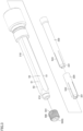
Fig. 3 is an exploded perspective view of the electrode holder and a fin member. - Embodiments of the present disclosure will be described with reference to the drawings. In the drawings referenced below, the same or corresponding members are denoted by the same numerals.
-
Fig. 1 is a cross-sectional perspective view of a plasma processing apparatus in one embodiment of the present disclosure. Thisplasma processing apparatus 1 is suitably used for surface modification of a workpiece. - As shown in
Fig. 1 ,plasma processing apparatus 1 includes aninner electrode 100, anelectrode holder 200, anouter electrode 300, aninsulating member 400, afin member 500, anozzle 600, agas supply unit 700, and anintermediate member 750. -
Inner electrode 100 has a linearly extending shape.Inner electrode 100 is made of tungsten, for example. A voltage is applied toinner electrode 100 from a power supply which is not shown. -
Electrode holder 200 holdsinner electrode 100.Electrode holder 200 is made of copper, for example.Electrode holder 200 will be detailed later herein. -
Outer electrode 300 is formed in a tubular shape. More specifically,outer electrode 300 is formed in a cylindrical shape.Outer electrode 300 surroundsinner electrode 100 andelectrode holder 200. -
Insulating member 400 is arranged betweeninner electrode 100 andouter electrode 300 and betweenelectrode holder 200 andouter electrode 300. Insulatingmember 400 surroundsinner electrode 100 andelectrode holder 200. Insulatingmember 400 is formed in a cylindrical shape. Insulatingmember 400 defines a position where plasma is generated betweeninner electrode 100 andouter electrode 300. As shown inFig. 1 , the position of a tip end ofinsulating member 400 is set to expose atip end 101 ofinner electrode 100 from this tip end. In other words, a process gas is converted into a plasma state in the vicinity oftip end 101 ofinner electrode 100 due to a discharge phenomenon that occurs between the vicinity oftip end 101 andouter electrode 300. -
Electrode holder 200 is now detailed. As shown inFigs. 1 to 3 ,electrode holder 200 has anouter holder 210, a firstinner holder 220, and a secondinner holder 230. -
Outer holder 210 surroundsinner electrode 100. As shown inFig. 1 , an inner circumferential surface ofouter holder 210 is provided with a reduced-diameter portion 211 that is gradually reduced in diameter toward a tip end (downstream side in a flow direction of the process gas). As shown inFig. 2 , an outer circumferential surface ofouter holder 210 has a contact surface S1 in contact with an inner circumferential surface ofinsulating member 400, and a flow path forming surface S2 spaced from the inner circumferential surface of insulatingmember 400. Flow path forming surface S2 forms a flow path of the process gas together with the inner circumferential surface of insulatingmember 400. As shown inFig. 3 , flow path forming surface S2 is formed to be flat. - As shown in
Figs. 1 and3 ,outer holder 210 has aholding portion 212 that holdsfin member 500.Holding portion 212 is formed downstream of flow path forming surface S2 in the flow direction of the process gas. - First
inner holder 220 is arranged on the inner side ofouter holder 210. Firstinner holder 220 surroundsinner electrode 100. As shown inFig. 3 , a tip end portion of firstinner holder 220 is provided with a slit S22 extending in a direction parallel to an axial direction of firstinner holder 220. Therefore, when firstinner holder 220 is inserted intoouter holder 210, atip end 221 of firstinner holder 220 is pressed against reduced-diameter portion 211 ofouter holder 210, and is thereby pressed to contactinner electrode 100. As shown inFig. 1 , an inner circumferential surface of a base end portion of firstinner holder 220 is provided with a reduced-diameter portion 222 that is gradually reduced in diameter toward the tip end. - Second
inner holder 230 is arranged on the inner side ofouter holder 210. Secondinner holder 230 surroundsinner electrode 100. As shown inFig. 3 , a tip end portion of secondinner holder 230 is provided with a slit S23 extending in a direction parallel to an axial direction of secondinner holder 230. Therefore, when secondinner holder 230 is inserted intoouter holder 210, atip end 231 of secondinner holder 230 is pressed against reduced-diameter portion 222 of firstinner holder 220, and is thereby pressed to contactinner electrode 100. -
Fin member 500 is a member for forming a swirling flow aroundinner electrode 100 by causing the process gas (such as argon or air) supplied to the inner side of insulatingmember 400 to swirl. As shown inFig. 3 , an outer circumferential surface offin member 500 is provided with a plurality ofgrooves 501.Fin member 500 is held on holdingportion 212 ofelectrode holder 200. As shown inFig. 1 , the outer circumferential surface offin member 500 is in contact with the inner circumferential surface of insulatingmember 400. Therefore, a position ofholding portion 212 relative to insulatingmember 400 is effectively determined throughfin member 500. That is, a central axis ofinner electrode 100 coincides with a central axis ofinsulating member 400 byfin member 500,outer holder 210 and firstinner holder 220. - As shown in
Fig. 1 ,fin member 500 is spaced frominner electrode 100. Specifically,fin member 500 has a heldportion 510 and an extendingportion 520. - Held
portion 510 is fit onholding portion 212. Stated another way, heldportion 510 is fit to holdingportion 212 from the outer circumferential side ofholding portion 212. - Extending
portion 520 extends downstream from heldportion 510 in the flow direction of the processed gas. As shown inFig. 1 , an innercircumferential surface 500S of extendingportion 520 is spaced frominner electrode 100. - As shown in
Fig. 1 , a length L betweenfin member 500 and tip end 101 ofinner electrode 100 is preferably more than or equal to three times and less than or equal to ten times as long as an inner diameter ϕ of insulatingmember 400, and is more preferably more than or equal to five times and less than or equal to seven times as long as this inner diameter ϕ. This facilitates a blow of the process gas in a fully developed state fromnozzle 600. Note that length L refers to the length betweentip end 101 ofinner electrode 100 and a downstream end ofgrooves 501 formed infin member 500. -
Nozzle 600 is a portion that blows the swirling flow converted into a plasma state.Nozzle 600 is connected to a tip end portion ofouter electrode 300. Insulatingmember 400 has a tip end portion (downstream end) 402 secured tonozzle 600. -
Gas supply unit 700 is a portion for supplying the process gas to the inner side of insulatingmember 400.Gas supply unit 700 is provided at a position spaced fromouter electrode 300 in a direction parallel to the central axis ofinner electrode 100. - As shown in
Fig. 1 ,intermediate member 750 is interposed betweengas supply unit 700 andouter electrode 300. In other words,gas supply unit 700 is connected to a base end portion ofouter electrode 300 withintermediate member 750 therebetween.Intermediate member 750 has insulating property. Insulatingmember 400 has abase end portion 401 secured tointermediate member 750. - In
plasma processing apparatus 1 described above, when a process gas is supplied fromgas supply unit 700, the process gas passes between an inner circumferential surface ofintermediate member 750 and the outer circumferential surface ofouter holder 210 inelectrode holder 200 to flow to the inner side of insulatingmember 400, and passes between insulatingmember 400 and flow path forming surface S2 to reachfin member 500. The process gas is then turned into a swirling flow aroundinner electrode 100 by passing throughgrooves 501 infin member 500, converted into a plasma state in the vicinity oftip end 101 ofinner electrode 100, and blown fromnozzle 600. - As described above, in
plasma processing apparatus 1 according to the present embodiment, the swirling flow formed atfin member 500 increases the length of the flow path of the process gas betweeninner electrode 100 andouter electrode 300, which leads to the generation of stable plasma. Further, since insulatingmember 400 is directly or indirectly secured toouter electrode 300, andfin member 500 is secured toelectrode holder 200 and is in contact with the inner circumferential surface of insulatingmember 400, misalignment of the central axis ofinner electrode 100 with respect toouter electrode 300 is effectively suppressed. - In addition, since
inner electrode 100 is held at a plurality of locations includingtip end 221 of firstinner holder 220 and tip end 231 of secondinner holder 230, the misalignment of the central axis ofinner electrode 100 with respect toouter electrode 300 is more reliably suppressed. - It will be understood by those skilled in the art that the plurality of exemplary embodiments described above are specific examples of the following aspects.
- [Aspect 1] A plasma processing apparatus comprising:
- an inner electrode that receives application of a voltage;
- an electrode holder that holds the inner electrode;
- an outer electrode formed in a tubular shape, the outer electrode surrounding the inner electrode and the electrode holder;
- an insulating member arranged between the inner electrode and the outer electrode and between the electrode holder and the outer electrode, the insulating member surrounding the inner electrode and the electrode holder;
- a fin member for forming a swirling flow around the inner electrode by causing a process gas supplied to an inner side of the insulating member to swirl; and
- a nozzle that blows the swirling flow converted into a plasma state, wherein
- the insulating member is directly or indirectly secured to the outer electrode, and
- the fin member is secured to the electrode holder while being spaced from the inner electrode, and is in contact with an inner circumferential surface of the insulating member.
- [Aspect 2] The plasma processing apparatus according to
aspect 1, wherein the electrode holder has- a contact surface in contact with the inner circumferential surface of the insulating member, and
- a flow path forming surface spaced from the inner circumferential surface of the insulating member, the flow path forming surface forming a flow path of the process gas together with the inner circumferential surface of the insulating member.
- [Aspect 3] The plasma processing apparatus according to
aspect 2, wherein the electrode holder has a holding portion that holds the fin member, and
the holding portion is formed downstream of the flow path forming surface in a flow direction of the process gas. - [Aspect 4] The plasma processing apparatus according to any one of
aspects 1 to 3, further comprising:- a gas supply unit provided at a position spaced from the outer electrode in a direction parallel to a central axis of the inner electrode, the gas supply unit supplying the process gas; and
- an intermediate member interposed between the gas supply unit and the outer electrode, wherein
- the insulating member has a base end portion secured to the intermediate member, and
- the insulating member has a tip end portion secured to the nozzle.
- [Aspect 5] The plasma processing apparatus according to any one of
aspects 1 to 4, wherein a length between the fin member and a tip end of the inner electrode is more than or equal to five times and less than or equal to twenty times as long as an inner diameter of the insulating member. - Although the embodiments of the present invention have been described, it should be understood that the embodiments disclosed herein are illustrative and non-restrictive in every respect. The scope of the present invention is defined by the terms of the claims, and is intended to include any modifications within the scope and meaning equivalent to the terms of the claims.
Claims (5)
- A plasma processing apparatus (1) comprising:an inner electrode (100) that receives application of a voltage;an electrode holder (200) that holds the inner electrode (100);an outer electrode (300) formed in a tubular shape, the outer electrode (300) surrounding the inner electrode (100) and the electrode holder (200);an insulating member (400) arranged between the inner electrode (100) and the outer electrode (300) and between the electrode holder (200) and the outer electrode (300), the insulating member (400) surrounding the inner electrode (100) and the electrode holder (200);a fin member (500) for forming a swirling flow around the inner electrode (100) by causing a process gas supplied to an inner side of the insulating member (400) to swirl; anda nozzle (600) that blows the swirling flow converted into a plasma state, whereinthe insulating member (400) is directly or indirectly secured to the outer electrode (300), andthe fin member (500) is secured to the electrode holder (200) while being spaced from the inner electrode (100), and is in contact with an inner circumferential surface of the insulating member (400).
- The plasma processing apparatus (1) according to claim 1, wherein the electrode holder (200) hasa contact surface (S1) in contact with the inner circumferential surface of the insulating member (400), anda flow path forming surface (S2) spaced from the inner circumferential surface of the insulating member (400), the flow path forming surface (S2) forming a flow path of the process gas together with the inner circumferential surface of the insulating member (400).
- The plasma processing apparatus (1) according to claim 2, whereinthe electrode holder (200) has a holding portion (212) that holds the fin member (500), andthe holding portion (212) is formed downstream of the flow path forming surface (S2) in a flow direction of the process gas.
- The plasma processing apparatus (1) according to claim 1, further comprising:a gas supply unit (700) provided at a position spaced from the outer electrode (300) in a direction parallel to a central axis of the inner electrode (100), the gas supply unit (700) supplying the process gas; andan intermediate member (750) interposed between the gas supply unit (700) and the outer electrode (300), whereinthe insulating member (400) has a base end portion (401) secured to the intermediate member (750), andthe insulating member (400) has a tip end portion (402) secured to the nozzle (600).
- The plasma processing apparatus (1) according to claim 1, wherein a length (L) between the fin member (500) and a tip end of the inner electrode (100) is more than or equal to three times and less than or equal to ten times as long as an inner diameter (ϕ) of the insulating member (400).
Applications Claiming Priority (1)
| Application Number | Priority Date | Filing Date | Title |
|---|---|---|---|
| JP2023100803A JP2025001296A (en) | 2023-06-20 | 2023-06-20 | Plasma Processing Equipment |
Publications (1)
| Publication Number | Publication Date |
|---|---|
| EP4482259A1 true EP4482259A1 (en) | 2024-12-25 |
Family
ID=91581870
Family Applications (1)
| Application Number | Title | Priority Date | Filing Date |
|---|---|---|---|
| EP24182491.1A Pending EP4482259A1 (en) | 2023-06-20 | 2024-06-17 | Plasma processing apparatus |
Country Status (4)
| Country | Link |
|---|---|
| US (1) | US20240429029A1 (en) |
| EP (1) | EP4482259A1 (en) |
| JP (1) | JP2025001296A (en) |
| CN (1) | CN119172912A (en) |
Citations (6)
| Publication number | Priority date | Publication date | Assignee | Title |
|---|---|---|---|---|
| JPH0654471U (en) | 1992-12-25 | 1994-07-26 | 新日本製鐵株式会社 | Gas guide for plasma torch |
| JP2005056647A (en) * | 2003-08-01 | 2005-03-03 | Haiden Kenkyusho:Kk | Method and device for generating plasma |
| US20080283153A1 (en) * | 2007-05-09 | 2008-11-20 | Air Products And Chemicals, Inc. | Furnace atmosphere activation method and apparatus |
| EP2209354A2 (en) * | 2009-01-14 | 2010-07-21 | Reinhausen Plasma GmbH | Generator for generating a bundled plasma jet |
| DE102013017109A1 (en) * | 2013-10-15 | 2015-04-16 | Fraunhofer-Gesellschaft zur Förderung der angewandten Forschung e.V. | Method and device for producing particles in an atmospheric pressure plasma |
| CN116078127A (en) * | 2023-03-03 | 2023-05-09 | 浙大城市学院 | Dielectric Barrier Discharge Tube with Needle Electrode Cooperating with Column Multi-channel Adsorption of Catalyst |
-
2023
- 2023-06-20 JP JP2023100803A patent/JP2025001296A/en active Pending
-
2024
- 2024-06-13 US US18/741,954 patent/US20240429029A1/en active Pending
- 2024-06-17 EP EP24182491.1A patent/EP4482259A1/en active Pending
- 2024-06-18 CN CN202410785026.5A patent/CN119172912A/en active Pending
Patent Citations (6)
| Publication number | Priority date | Publication date | Assignee | Title |
|---|---|---|---|---|
| JPH0654471U (en) | 1992-12-25 | 1994-07-26 | 新日本製鐵株式会社 | Gas guide for plasma torch |
| JP2005056647A (en) * | 2003-08-01 | 2005-03-03 | Haiden Kenkyusho:Kk | Method and device for generating plasma |
| US20080283153A1 (en) * | 2007-05-09 | 2008-11-20 | Air Products And Chemicals, Inc. | Furnace atmosphere activation method and apparatus |
| EP2209354A2 (en) * | 2009-01-14 | 2010-07-21 | Reinhausen Plasma GmbH | Generator for generating a bundled plasma jet |
| DE102013017109A1 (en) * | 2013-10-15 | 2015-04-16 | Fraunhofer-Gesellschaft zur Förderung der angewandten Forschung e.V. | Method and device for producing particles in an atmospheric pressure plasma |
| CN116078127A (en) * | 2023-03-03 | 2023-05-09 | 浙大城市学院 | Dielectric Barrier Discharge Tube with Needle Electrode Cooperating with Column Multi-channel Adsorption of Catalyst |
Also Published As
| Publication number | Publication date |
|---|---|
| US20240429029A1 (en) | 2024-12-26 |
| CN119172912A (en) | 2024-12-20 |
| JP2025001296A (en) | 2025-01-08 |
Similar Documents
| Publication | Publication Date | Title |
|---|---|---|
| US5747767A (en) | Extended water-injection nozzle assembly with improved centering | |
| US6744013B2 (en) | Welding torch for use in gas metal arc welding | |
| US6472631B1 (en) | Strain relief mechanism for a plasma arc torch | |
| EP1764179A3 (en) | Contact tip with a flange ; Insulated protective sleeve ; Metal nozzle with gripping means ; Torch for arc welding with a wire with such contact tip, insulating protective sleeve and metal nozzle | |
| US10863610B2 (en) | Plasma torch and components thereof | |
| CA2815260C (en) | Electrode for plasma cutting torches and use of same | |
| EP4482259A1 (en) | Plasma processing apparatus | |
| US6621038B2 (en) | Torch for powder plasma buildup welding | |
| GB2373471A (en) | Contact tip for MIG welding gun | |
| JP3006262B2 (en) | Plasma cutting torch | |
| KR20190043347A (en) | Welding torch having a diffuser with directional | |
| JP3529043B2 (en) | Arc welding equipment | |
| CN214921313U (en) | Plasma cutting torch for non-contact cutting without arc striking wire | |
| JP2012086247A (en) | Tig welding torch | |
| JP7474676B2 (en) | Plasma torch and center pipe for plasma torch | |
| JP7475199B2 (en) | Welding torch | |
| JP3109412B2 (en) | Arc welding torch and its arc welding cable | |
| JP4391847B2 (en) | Plasma welding torch | |
| JP7475084B1 (en) | Coaxial microwave plasma torch | |
| JPH0539834Y2 (en) | ||
| CN216730336U (en) | Welding wire lengthening clamp | |
| JP5248753B2 (en) | Welding torch | |
| JP2003001419A (en) | Arc welding equipment | |
| JP2024098721A (en) | Coaxial microwave plasma torch | |
| JP6602615B2 (en) | Welding torch |
Legal Events
| Date | Code | Title | Description |
|---|---|---|---|
| PUAI | Public reference made under article 153(3) epc to a published international application that has entered the european phase |
Free format text: ORIGINAL CODE: 0009012 |
|
| STAA | Information on the status of an ep patent application or granted ep patent |
Free format text: STATUS: REQUEST FOR EXAMINATION WAS MADE |
|
| 17P | Request for examination filed |
Effective date: 20240617 |
|
| AK | Designated contracting states |
Kind code of ref document: A1 Designated state(s): AL AT BE BG CH CY CZ DE DK EE ES FI FR GB GR HR HU IE IS IT LI LT LU LV MC ME MK MT NL NO PL PT RO RS SE SI SK SM TR |