EP4482129A1 - Elektronische vorrichtung mit scharniervorrichtung - Google Patents
Elektronische vorrichtung mit scharniervorrichtung Download PDFInfo
- Publication number
- EP4482129A1 EP4482129A1 EP23820001.8A EP23820001A EP4482129A1 EP 4482129 A1 EP4482129 A1 EP 4482129A1 EP 23820001 A EP23820001 A EP 23820001A EP 4482129 A1 EP4482129 A1 EP 4482129A1
- Authority
- EP
- European Patent Office
- Prior art keywords
- housing
- slide rail
- rotator
- hinge
- electronic device
- Prior art date
- Legal status (The legal status is an assumption and is not a legal conclusion. Google has not performed a legal analysis and makes no representation as to the accuracy of the status listed.)
- Pending
Links
Images


Classifications
-
- G—PHYSICS
- G06—COMPUTING OR CALCULATING; COUNTING
- G06F—ELECTRIC DIGITAL DATA PROCESSING
- G06F1/00—Details not covered by groups G06F3/00 - G06F13/00 and G06F21/00
- G06F1/16—Constructional details or arrangements
- G06F1/1613—Constructional details or arrangements for portable computers
- G06F1/1615—Constructional details or arrangements for portable computers with several enclosures having relative motions, each enclosure supporting at least one I/O or computing function
- G06F1/1616—Constructional details or arrangements for portable computers with several enclosures having relative motions, each enclosure supporting at least one I/O or computing function with folding flat displays, e.g. laptop computers or notebooks having a clamshell configuration, with body parts pivoting to an open position around an axis parallel to the plane they define in closed position
-
- G—PHYSICS
- G06—COMPUTING OR CALCULATING; COUNTING
- G06F—ELECTRIC DIGITAL DATA PROCESSING
- G06F1/00—Details not covered by groups G06F3/00 - G06F13/00 and G06F21/00
- G06F1/16—Constructional details or arrangements
- G06F1/1613—Constructional details or arrangements for portable computers
- G06F1/1633—Constructional details or arrangements of portable computers not specific to the type of enclosures covered by groups G06F1/1615 - G06F1/1626
- G06F1/1637—Details related to the display arrangement, including those related to the mounting of the display in the housing
- G06F1/1652—Details related to the display arrangement, including those related to the mounting of the display in the housing the display being flexible, e.g. mimicking a sheet of paper, or rollable
-
- G—PHYSICS
- G06—COMPUTING OR CALCULATING; COUNTING
- G06F—ELECTRIC DIGITAL DATA PROCESSING
- G06F1/00—Details not covered by groups G06F3/00 - G06F13/00 and G06F21/00
- G06F1/16—Constructional details or arrangements
- G06F1/1613—Constructional details or arrangements for portable computers
- G06F1/1633—Constructional details or arrangements of portable computers not specific to the type of enclosures covered by groups G06F1/1615 - G06F1/1626
- G06F1/1675—Miscellaneous details related to the relative movement between the different enclosures or enclosure parts
- G06F1/1681—Details related solely to hinges
-
- H—ELECTRICITY
- H04—ELECTRIC COMMUNICATION TECHNIQUE
- H04M—TELEPHONIC COMMUNICATION
- H04M1/00—Substation equipment, e.g. for use by subscribers
- H04M1/02—Constructional features of telephone sets
- H04M1/0202—Portable telephone sets, e.g. cordless phones, mobile phones or bar type handsets
- H04M1/0206—Portable telephones comprising a plurality of mechanically joined movable body parts, e.g. hinged housings
- H04M1/0208—Portable telephones comprising a plurality of mechanically joined movable body parts, e.g. hinged housings characterized by the relative motions of the body parts
- H04M1/0214—Foldable telephones, i.e. with body parts pivoting to an open position around an axis parallel to the plane they define in closed position
- H04M1/0216—Foldable in one direction, i.e. using a one degree of freedom hinge
- H04M1/022—The hinge comprising two parallel pivoting axes
-
- H—ELECTRICITY
- H04—ELECTRIC COMMUNICATION TECHNIQUE
- H04M—TELEPHONIC COMMUNICATION
- H04M1/00—Substation equipment, e.g. for use by subscribers
- H04M1/02—Constructional features of telephone sets
- H04M1/0202—Portable telephone sets, e.g. cordless phones, mobile phones or bar type handsets
- H04M1/026—Details of the structure or mounting of specific components
- H04M1/0266—Details of the structure or mounting of specific components for a display module assembly
- H04M1/0268—Details of the structure or mounting of specific components for a display module assembly including a flexible display panel
Definitions
- An electronic device may include a foldable electronic device including a first housing and a second housing foldably connected to the first housing through at least one hinge device (e.g., a hinge module or a hinge structure).
- the first housing and the second housing may be operated through at least one hinge device during transition to a folded state and/or anunfolded state.
- the foldable electronic device may be operated in an in-folding method and/or an out-folding method by rotating the first housing and the second housing with respect to each other within a designated range from 0 degrees to 360 degrees through at least one hinge device.
- the foldable electronic device may include a flexible display disposed to cross the first housing and the second housing in an unfolded state.
- the flexible display In a folded state, the flexible display may have a folding area deformed into a designated shape.
- the first housing and the second housing need to be designed to rotate about rotational axes located separately from a folding axis of the flexible display to enable the folding area of the flexible display to be deformed into a curved shape.
- the folding area of the flexible display may be deformed into various curved shapes (e.g., a "U" shape or a waterdrop shape) in an inner space of the electronic device according to a folding operation.
- the flexible display when fixed rotational axes are configured in consideration of only the position of the flexible display in the folded/unfolded state, the flexible display may be compressed while transitioning from the unfolded state to the folded state, and as a result, bucklingof the display may occur.
- the configuration in which an assembly structure for the pivot rotation of the rotator and the arm is arranged to be operated outside the hinge device may cause difficulties in securing an efficient arrangement space in the inner space of an electronic device that is gradually becoming slimmer, and may increase an unwanted mobilityof each part due to design/assembly deviations between parts, thereby degrading operation reliability of the electronic device.
- the disclosure provides an electronic device including a hinge device that advantageously improves operational reliability of a flexible display.
- the disclosure provides an electronic device including a hinge device capable of reducing surface quality deterioration even after frequent operations.
- an electronic device includes:a first housing; a second housing; a hinge device configured to connect the first housing and the second housing and to be foldable with respect to a folding axis; and a flexible display supported by the first housing and the second housing, wherein the hinge device includes: a hinge bracket; a first slide rail movably disposed at the hinge bracket on a first side of the folding axis; a second slide rail movably disposed at the hinge bracket on a second side of the folding axis; a first rotator rotatably disposed on the first slide rail; and a second rotator rotatably disposed on the second slide rail, and wherein the first slide rail and the second slide rail are configured to move a designated linear distance relative to the hinge bracket when the electronic device transitions from a folded state to an unfolded state or when the electronic device transitions from the unfolded state to the folded state.
- the first rotational axis may be located at an identical position relative to the folding axis in the folded state and the unfolded state
- the second rotational axis may be located at an identical position relative to the folding axis in the folded state and the unfolded state.
- the first slide rail and the second slide rail may each have a maximum linear movement distance corresponding to a designated intermediate folding angle of the hinge device.
- the flexible display may include a folding area, and the intermediate folding angle may be based on a deformed shape of the folding area in the folded state.
- the hinge bracket may include a first rail receiving part and a second rail receiving part,wherein the first slide rail may include a guide groove comprising a designated length, wherein the guide groove of the first slide rail may be coupled to the first rail receiving part such that the first slide rail is linearly movable, andthe second slide rail may include a guide groove having a designated length, wherein the guide groove of the second slide rail may be coupled to the second rail receiving part such that the second slide rail is linearly movable.
- the first rotator may include a curved rotation part including a first guide rail
- the second rotator may include a curved rotation part including a second guide rail
- the first slide rail includes a first curved guide rib disposed on an outer surface thereof, and the first rotator is rotatably coupled to the first slide rail via insertion of the first curved guide rib into the first guide rail
- the second slide rail includes a second curved guide rib disposed on an outer surface thereof, and the second rotator isrotatably coupled to the second slide rail via insertion of the second curved guide rib into the second guide rail.
- the electronic device may further include: a first support rotator having one end rotatably coupled to the hinge bracket and the other end rotatably coupled to the first rotator; and a second support rotator having one end rotatably coupled to the hinge bracket and the other end rotatably coupled to the second rotator.
- the electronic device may further include: a first hinge plate coupled to the first support rotator; and a second hinge plate coupled to the second support rotator, wherein in the unfolded state, the first housing, the first hinge plate, the second housing, and the second hinge plate form a plane.
- the first housing and the first hinge plate may form a first plane
- the second housing and the second hinge plate may form a second plane, wherein the first plane and the second plane are different.
- a hinge device for a foldable electronic device having a folding axis includes: a hinge bracket; a first slide rail movably disposed at the hinge bracket on a first side of the folding axis; a second slide rail movably disposed at the hinge bracket on a second side of the folding axis; a first rotator disposed on the first slide rail to be rotatable around a first rotational axis; and a second rotator disposed on the second slide rail to be rotatable around a second rotational axis, wherein, the first rotational axis is moved through movement of the first slide rail, and the second rotational axis is moved through movement of the second slide rail when the electronic device transitions from a folded state to an unfolded state or when the electronic device transitions from the unfolded state to the folded state.
- the first rotational axis may be located at an identical position relative to the folding axis in the folded state and the unfolded state
- the second rotational axis may be located at an identical position relative to the folding axis in the folded state and the unfolded state.
- the hinge device may further include a first support rotator having one end rotatably coupled to the hinge bracket and the other end rotatably coupled to the first rotator; and a second support rotator having one end rotatably coupled to the hinge bracket and the other end rotatably coupled to the second rotator.
- An electronic device may have an assembly structure in whichrotational axis linearly reciprocates in a designated directionwhile a housing is rotated, through a slide rail arranged as a direct component of a hinge device, so that unwanted mobility generated during operation may be reduced, and operation reliability of the electronic device may be improved.
- this assembly structure may advantageously reduce surface quality deterioration of a flexible display even after frequent folding operations.
- FIGS. 1A and 1B are diagrams illustrating a front view and a rear view, respectively, of an unfolded stateof an electronic device according to various embodiments.
- FIGS. 2A and 2B are diagrams illustrating a front view and a rear view, respectively, of a folded state of an electronic device according to various embodiments.
- an electronic device 200 may include a pair of housings 210 and 220 (e.g., a foldable housing structure) rotatably coupled to each other with reference to folding axis A through a hinge device (e.g., a hinge device 320 of FIG.
- a hinge device e.g., a hinge device 320 of FIG.
- the first housing 210 and the second housing 220 may be asymmetrically folded with reference to the folding axis A. According to an embodiment, the angle or the distance between the first housing 210 and the second housing 220 may vary depending on whether the electronic device 200 is in an unfolded state, a folded state, or an intermediate state.
- the recess 201 may have substantially the same shape as the first display 230.
- the first housing 210 may include a first protection frame 213a (e.g., a first decoration member) which is, when seen from above the first display 230, coupled to the first side member 213, disposed to overlap with an edge of the first display 230, so as to cover the edge of the first display 230 to allow the same not to be seen from the outside.
- the first protection frame 213a may be integrally formed with the first side member 213.
- the first housing 210 and the second housing 220 may meet at an about 180-degree angle, and a first area 230a, a second area 230b, and a folding area 230c of the first display 230 may form the same plane and arranged to be oriented in substantially the same direction (e.g., a z-axis direction).
- the electronic device 200 may include at least one of at least one display 230 and 300 disposed on the first housing 210 and/or the second housing 220, an input device 215, sound output devices 227 and 228, sensor modules 217a, 217b, and 226, camera modules 216a, 216b, and 225, a key input device 219, an indicator, or a connector port 229.
- the electronic device 200 may omit at least one of the elements, or may additionally include at least one another element.
- the at least one display 230 and 300 may include a first display 230 (e.g., a flexible display) disposed to be supported by the third surface 221 of the second housing 220 from the first surface 211 of the first housing 210 through the hinge device (e.g., the hinge device 320 of FIG. 3 ), and a second display 300 disposed to be at least partially seen from the outside through the fourth surface 222 in a space in the second housing 220.
- the second display 300 may be disposed to be seen from the outside through the second surface 212 in a space in the first housing 210.
- the first display 230 may be mainly used in the unfolded state of the electronic device 200
- the second display 300 may be mainly used in the folded state of the electronic device 200
- the electronic device 200 may control, in the intermediate state, the first display 230 and/or the second display 300 to be used, based on a folding angle between the first housing 210 and the second housing 220.
- the first display 230 may be disposed in a receiving space formed by the pair of housings 210 and 220.
- the first display 230 may be disposed in a recess 201 formed by the pair of housings 210 and 220, and may be disposed to occupy substantially the most of the front surface of the electronic device 200in the unfolded state.
- the first display 230 may include a flexible display having at least one area which can be deformed into a plane or a curved surface.
- the first display 230 may include the first area 230a facing the first housing 210 and the second area 230b facing the second housing 220.
- the first display 230 may include the folding area 230c including a part of the first area 230a and a part of the second area 230b with respect to the folding axis A.
- at least a part of the folding area 230c may include an area corresponding to the hinge device (e.g., the hinge device 320 of FIG. 3 ).
- a division of an area of the first display 230 merely corresponds to an example physical division by the pair of housings 210 and 220 and the hinge device (e.g., the hinge device 320 of FIG.
- the first rear cover 240 may be formed of, for example, an opaque plate such as coded or colored glass, ceramic, polymer, metal (e.g., aluminum, stainless steel (STS), or magnesium), or a combination of at least two of the materials above.
- the second rear cover 250 may be substantially formed of, for example, a transparent plate such as glass or polymer. Accordingly, the second display 300 may be disposed to be seen from the outside through the second rear cover 250 in a space in the second housing 220.
- the input device 215 may include a microphone.
- the input device 215 may include multiple microphones arranged to detect the direction of sound.
- the sound output devices 227 and 228 may include speakers.
- the sound output devices 227 and 228 may include a call receiver 227 disposed through the fourth surface 222 of the second housing 220 and an external speaker 228 disposed through at least a part of the second side member 223 of the second housing 220.
- the input device 215, the sound output devices 227 and 228, and the connector 229 may be disposed in spaces of the first housing 210 and/or the second housing 220, and may be exposed to an external environment through at least one hole formed through the first housing 210 and/or the second housing 220.
- holes formed through the first housing 210 and/or the second housing 220 may be commonly used for the input device 215 and the sound output devices 227 and 228.
- the sound output devices 227 and 228 may include a speaker (e.g., a piezo speaker) operating without including a hole formed through the first housing 210 and/or the second housing 220.
- the camera modules 216a, 216b, and 225 may include a first camera module 216a disposed on the first surface 211 of the first housing 210, a second camera module 216b disposed on the second surface 212 of the first housing 210, and/or a third camera module 225 disposed on the fourth surface 222 of the second housing 220.
- the electronic device 200 may include a flash 218 disposed around the second camera module 216b.
- the flash 218 may include, for example, a light-emitting diode or a xenon lamp.
- the camera modules 216a, 216b, and 225 may include one or multiple lenses, an image sensor, and/or an image signal processor.
- At least one of the camera modules 216a, 216b, and 225 may include two or more lenses (e.g., wide-angle and telephoto lenses) and image sensors, and may be arranged together on one surface of the first housing 210 and/or the second housing 220.
- the sensor modules 217a, 217b, and 226 may include at least one of a gesture sensor, a grip sensor, a color sensor, an infrared (IR) sensor, an illuminance sensor, an ultrasonic sensor, an iris recognition sensor, or a distance detection sensor (e.g., a time of flight (TOF) sensor or a light detection and ranging (LiDAR)).
- a gesture sensor e.g., a grip sensor, a color sensor, an infrared (IR) sensor, an illuminance sensor, an ultrasonic sensor, an iris recognition sensor, or a distance detection sensor (e.g., a time of flight (TOF) sensor or a light detection and ranging (LiDAR)).
- a grip sensor e.g., a grip sensor, a color sensor, an infrared (IR) sensor, an illuminance sensor, an ultrasonic sensor, an iris recognition sensor, or a distance detection sensor (e.g., a
- the electronic device 200 may further include an unillustrated sensor module, for example, at least one of an atmospheric sensor, a magnetic sensor, a biometric sensor, a temperature sensor, a humidity sensor, or a fingerprint recognition sensor.
- the fingerprint recognition sensor may be disposed through at least one of the first side member 213 of the first housing 210 and/or the second side member 223 of the second housing 220.
- the key input device 219 may be disposed to be exposed to the outside through the first side member 213 of the first housing 210. In an embodiment, the key input device 219 may be disposed to be exposed to the outside through the second side member 223 of the second housing 220. In an embodiment, the electronic device 200 may not include some or all of the key input device 219, and the key input device 219 may be implemented in another shape such as a soft key on the least one display 230 and 300. In an embodiment, the key input device 219 may be implemented using a pressure sensor included in the at least one display 230 and 300.
- the connector port 229 may include a connector (e.g., a USB connector or an IF module (an interface connector port module)) for transmitting or receiving data and/or power to and/or from an external electronic device.
- the connector port 229 may perform a function of transmitting or receiving an audio signal to or from the external electronic device together, or may further include a separate connector port (e.g., an ear jack hole) for performing a function of transmitting or receiving an audio signal to or from the external electronic device.
- At least one camera modules 216a and 225 of the camera modules 216a, 216b, and 225, at least one sensor module 217a and 226 of the sensor modules 217a, 217b, and 226, and/or an indicator may be arranged to be exposed through the at least one display 230 and 300.
- the at least one camera modules 216a and 225, the at least one sensor module 217a and 226, and/or the indicator may be arranged under an activated area (a display area) of the at least one display 230 and 300 in a space in the at least one housing 210 and 220, and may be arranged to come into contact with an external environment through a transparent area or an opening that is perforated to a cover member (e.g., a window layer of the first display 230 and/or the second rear cover 250).
- a cover member e.g., a window layer of the first display 230 and/or the second rear cover 250.
- an area in which the at least one display 230 and 300 and the at least one camera module 216a and 225 face each other may be formed as a transmission area having a predetermined transmission ratio, as a part of an area in which a content is displayed.
- the transmission area may be formed to have a transmission ratio in the range of about 5% to about 20%.
- the transmission area may include an area overlapping with an effective area (e.g., an angle of view area) of the at least one camera module 216a and 225, wherein an image is formed on the image sensor in the effective area, and light for generating an image passes through the effective area.
- the transmission area of the display 230 and 300 may include an area in which the density of a pixel is lower than that in a surrounding area.
- the transmission area may be replaced with an opening.
- the at least one camera module 216a and 225 may include an under-display camera (UDC) or an under-panel camera (UPC).
- UDC under-display camera
- UPC under-panel camera
- some camera modules or sensor modules 271a and 226 may be arranged to perform functions thereof without being visually exposed through the display.
- an area facing the sensor module 217a and 226 and/or the camera module 216a and 225 arranged under the display 230 and 300 corresponds to an under-display camera (UDC) structure, and a perforated opening is not necessarily required.
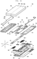
- FIG. 3A is an exploded perspective view of the electronic device 200 according to various embodiments of the disclosure.
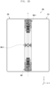
- FIG. 3B illustrates an arrangement structure of hinge devices in an electronic device according to various embodiments of the disclosure.
- the electronic device 200 may include a first display 230 (e.g., a flexible display), a second display 300, at least one hinge device 400 and 400-1, and a pair of support members 261 and 262, at least one substrate 270 (e.g., a printed circuit board (PCB)), a first housing 210, a second housing 220, a first rear cover 240, and/or a second rear cover 250.
- a first display 230 e.g., a flexible display
- a second display 300 e.g., a flexible display
- at least one hinge device 400 and 400-1 e.g., a pair of support members 261 and 262
- at least one substrate 270 e.g., a printed circuit board (PCB)
- PCB printed circuit board
- the first display 230 may include a display panel 235 (e.g., a flexible display panel) and a support plate 236 disposed under the display panel 235.
- the first display 230 may include a pair of reinforcing plates 237 and 238 disposed under the supporting plate 236. In some embodiments, the pair of reinforcing plates 237 and 238 may be omitted.
- the display panel 235 may include a first panel area 235a corresponding to a first area (e.g., the first area 230a in FIG.
- the support plate 236 may be disposed between the display panel 235 and the pair of support members 261 and 262 and may be formed to have a material and shape for providing a planar support structure for the first panel area 235a and the second panel area 235b.
- the support plate 236 may be formed of a conductive material (e.g., metal) or a non-conductive material (e.g., a polymer or fiber reinforced plastic (FRP)).
- the pair of reinforcing plates 237 and 238 may bedisposed between the support plate 236 and the pair of support members 261 and 262 and may include the first reinforcing plate 237 disposed to correspond to at least a part of the first panel area 235a and third panel area 235c, and the second reinforcing plate 238 disposed to correspond to at least a part of the second panel area 235b and the third panel area 235c.
- the pair of reinforcing plates 237 and 238 may be formed of a metal material (e.g., SUS) to advantageouslyreinforce a ground connection structure and rigidity for the first display 230.
- the electronic device 200 may include at least one wiring member 263 (e.g., a flexible printed circuit board (FPCB)) disposed from at least a part of the first support member 261 to a part of the second support member 262 across the at least one hinge device 400 and 400-1.
- the first support member 261 may extend from the first lateral member 213 or may be structurally combined with the first lateral member 213.
- the electronic device 200 may include a first space (e.g., the first space 2101 in FIG.
- the second housing 220 (e.g., the second housing structure) may be configured through a combination of the second lateral member 223, the second support member 262, and the second rear cover 250.
- at least a part of the at least one wiring member 263 and/or at least one hinge device 400 and 400-1 may be disposed to be supported through at least a part of the pair of support members 261 and 262.
- at least one wiring member 263 may be disposed in a direction (e.g., thex-axis direction) crossing the first support member 261 and the second support member 262.
- the at least one wiring member 263 may be arranged to have a length in a direction (e.g., the x-axis direction) substantially perpendicular to a folding axis (e.g., the y-axis or the folding axis A in FIG. 1A ).
- the at least one substrate 270 may include a first substrate 271 disposed in the first space 2101 and a second substrate 272 disposed in the second space 2201.
- the first substrate 271 and the second substrate 272 may include a plurality of electronic components arranged to implement various functions of the electronic device 200.
- the first substrate 271 and the second substrate 272 may be electrically connected through at least one wiring member 263.
- the electronic device 200 may include at least one battery 291 and 292.
- the at least one battery 291 and 292 may include a first battery 291 disposed in the first space 2101 of the first housing 210 and electrically connected to the first substrate 271, and a second battery disposed in the second space 2201 of the second housing 220 and electrically connected to the second substrate 272.
- the first support member 261 and the second support member 262 may further include at least one swelling hole for the first battery 291 and the second battery 292.
- the first housing 210 may include a first rotation support surface 214
- the second housing 220 may include a second rotation support surface 224 corresponding to the first rotation support surface 214
- the first rotation support surface 214 and the second rotation support surface 224 may include a curved surface corresponding to (naturally connected to) the curved outer surface of the hinge housing 310.
- the first rotation support surface 214 and the second rotation support surface 224 may cover the hinge housing 310 to prevent the hinge housing 310 from being exposed from the rear surface of the electronic device 200 or to expose only a part of the hinge housing 310.
- the first rotation support surface 214 and the second rotation support surface 224 may rotate along the curved outer surface of the hinge housing 310 and at least partially expose the hinge housing 310 from the rear surface of the electronic device 200.
- the electronic device 200 may include at least one antenna 276 disposed in the first space 2101.
- at least one antenna 276 may be disposed on the first battery 291 and the first rear cover 240 in the first space 2101.
- the at least one antenna 276 may include, for example, a near field communication (NFC) antenna, a wireless charging antenna, and/or a magnetic secure transmission (MST) antenna.
- the at least one antenna 276 may, for example, perform short-range communication with an external device or wirelessly transmit/receive power required for charging.
- the antenna structure may be formed by at least a part of the first lateral member 213 or the second lateral member 223 and/or a part of the first support member 261 and the second support member 262 or a combination thereof.
- the electronic device 200 may further include at least one electronic component assembly 274 and 275 and/or additional support members 263 and 273 disposed in the first space 2101 and/or the second space 2201.
- at least one electronic component assembly may include an interface connector port assembly 274 or a speaker assembly 275.
- the electronic device 200 may include a first waterproof member (WP1) disposed between the first reinforcing plate 237 and the first support member 261 and a second waterproof member (WP2) disposed between the second reinforcing plate 238 and the second support member 262.
- the first waterproof member (WP1) may provide at least one first waterproof space while being disposed between the first reinforcing plate 237 and the first support member 261.
- at least one first waterproof space may accommodate anarea corresponding to at least one electronic component (e.g., a camera module or a sensor module) disposed to be supported by the first support member 261.
- the second waterproof member may provide a second waterproof space while being disposed between the second reinforcing plate 238 and the second support member 262.
- the second waterproof space may accommodate at least a part of the bending partwhich is folded toward the rear surface of the first display 230.
- the second waterproof space may extend from the display panel of the first display 230 and may be disposed to surround at least a part of the bending partwhich is folded toward the rear surface thereof. Therefore, a control circuit (e.g., a display driver IC (DDI)) and a plurality of electric elements disposed in the bending part may be disposed in the second waterproof space to be protected from external moisture and/or foreign substances.
- a control circuit e.g., a display driver IC (DDI)
- a plurality of electric elements disposed in the bending part may be disposed in the second waterproof space to be protected from external moisture and/or foreign substances.
- the electronic device 200 may include a waterproof tape 241 disposed between the first rear cover 240 and the first housing 210.
- the electronic device 200 may include a bonding member 251 disposed between the second rear cover 250 and the second housing 220.
- the bonding member 251 may be disposed between the second display 300 and the second housing 220.
- the waterproof tape 241 may be replaced with the bonding member 251, and the bonding member 251 may be replaced with the waterproof tape 241.
- At least one hinge device 400 and 400-1 may include a first hinge device 400 and a second hinge device 400-1 disposed at one end and the other end in a direction parallel to the folding axis (F), respectively.
- the first hinge device 400 and the second hinge device 400-1 may have substantially the same configuration.
- the electronic device 200 may include a connection module 400-2 disposed between the first hinge device 400 and the second hinge device 400-1.
- the connection module 400-2 may be arranged through a combination of one or more gears and/or a combination of one or more links.
- the connection module 400-2 may be replaced with the first hinge device 400.
- the electronic device 200 may include a first hinge plate 311 and a second hinge plate 312 connected through at least one hinge device 400 and 400-1.
- the first hinge plate 311 may form the same plane as the first housing 210 in an unfolded state
- the second hinge plate 312 may form the same plane as the second housing 220 in an unfolded state.
- the flexible display 230 in a folded state, maybe deformed intoa waterdrop shape through at least one hinge device 400 and 400-1 and accommodated in the inner space of the electronic device 200.
- the first hinge plate 311 and the second hinge plate 312 may be moved to support at least a part of the folding area (e.g., the folding area 230c in FIG. 1A ) of the flexible display 230, which is deformed into the waterdrop shape, and in the folded state, the first housing 210 and the second housing 220 may be moved to support substantially undeformed flat parts (e.g., the first area 230a and the second area 230b in FIG. 1A ) of the flexible display 230. Therefore, the first hinge plate 311 may not form the same plane as the first housing 210 in a folded state, and the second hinge plate 312 may not also form the same plane as the second housing 220.
- the at least one hinge device 400 and 400-1 may be configured to induce the folding area 230c to be deformed into a designated shape (e.g., a waterdrop shape) in the folded state of the flexible display 230.
- a designated shape e.g., a waterdrop shape
- the first housing 210 and the second housing 220 may need to be designed to be rotatedaboutaxes(e.g., rotationalaxes (A1, A2) in FIG. 4B )that rotate with respect to positions different from the folding axis (F) of the flexible display 230 to enable the folding area 230c of the flexible display 230 to be deformable into a curved shape.
- the folding area 230c of the flexible display 230 which needs toform a waterdrop shape, may be compressed during the folding operation, and as a result, bucklingof the display may occur.
- the rotationalaxes (A1, A2) of the first housing 210 and the second housing 220 may be moved by at least a length by which the compressive force applied to the flexible display 230is relieved, thereby facilitatingsmooth deformation of the folding area 230c.
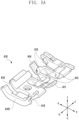
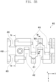
- FIG. 4A is an exploded perspective view of a hinge device according to various embodiments of the disclosure.
- FIG. 4B is a perspective view of a combined hinge device according to various embodiments of the disclosure.
- the hinge device 400 may include a hinge bracket 410, a first slide rail 421 disposed to be movable with respect toone side of the hinge bracket 410by a designated reciprocating distancearound to the folding axis (F), a second slide rail 422 disposed to be movable with respect tothe other side of the hinge bracket 410by a designated reciprocating distance, a first rotator 431 rotatably coupled to the first slide rail 421, a second rotator 432 rotatably coupled to the second slide rail 422, a first housing bracket 451 configured to fix the first rotator 431 to the first housing (e.g., the first housing 210 in FIG.
- first housing bracket 451 configured to fix the first rotator 431 to the first housing (e.g., the first housing 210 in FIG.
- the first hinge plate (e.g., the first hinge plate 311 in FIG. 3A ) may be fixed to the first support rotator 441
- the second hinge plate (e.g., the second hinge plate 312in FIG. 3A ) may be fixed to the second support rotator 442.
- At least one of the components described above may be formed of a polymer material and/or a metal material.
- the hinge bracket 410 may include a bracket body 4101 having a designated shape. According to an embodiment, in the bracket body 4101, the hinge bracket 410 may include a first rail receiving part 411 disposedat one sideof the folding axis (F) and configured to movably receive the first slide rail 421, and a second rail receiving part 414 disposed on the other side thereof and configured to movably receive the second slide rail 422.
- the hinge bracket 410 may include first receiving parts 412 disposed at the left and right side of (i.e., on either side of) the first rail receiving part 411 and configured to receive at least a part of the first rotator 431, andsecond receiving parts 415 disposedat the left and right side of (i.e., on either side of) the second rail receiving part 414 and configured to receiveat least a part of the second rotator 432.
- the first receiving parts 412 and the second receiving parts 415 only receive a part ofthe first rotator 431 and a part of the second rotator 432 which are interfered during the rotational motion of the first rotator 431 and the second rotator 432, and the first and second rotators 431 and 432 are not directly rotatably connected thereto.
- the hinge bracket 410 may include a third receiving part 413 configured to rotatably receivethe first support rotator 441and a fourth receiving part 416 configured to rotatably receive the second support rotator 442.
- the first rotator 431 may include a rotator body 4311 and a pair of rotation parts 4312 extending from the rotator body 4311 at a predetermined interval.
- the pair of rotation parts 4312 may be rotatably coupled to the first slide rail 421 and be at least partially received in the first receiving parts 412 of the hinge bracket 410 during a rotational motion.
- the second rotator 432 may also include a rotator body 4321 and a pair of rotation parts 4322 extending from the rotator body 4321 at a predetermined interval.
- the pair of rotation parts 4322 may be rotatably coupled to the second slide rail 422 and be at least partially received in the second receiving parts 415 of the hinge bracket 410 during a rotational motion.
- the first housing bracket 451 may include a fixed body 4511 fixed to the rotator body 4311 of the first rotator 431, a bracket rotation part 4512 disposed at one end of the fixed body 4511 and rotatably coupled to the second rotation part 4412 of the first support rotator 441, and a guide slit 4513 (e.g., a long hole) disposed at the other end of the fixed body 4511 and having a length to guide a hinge pin 4613 of a first arm 461 to be described later.
- a guide slit 4513 e.g., a long hole
- the second housing bracket 452 may also include a fixed body 4521 fixed to the rotator body 4321 of the second rotator 432, a bracket rotation part 4522 disposed at one end of the fixed body 4521 and rotatably coupled to the second rotation part 4422 of the second support rotator 442, and a guide slit 4523 (e.g., a long hole) disposed at the other end of the fixed body 4521 and having a length to guide a hinge pin 4623 of a second arm 462 to be described later.
- a guide slit 4523 e.g., a long hole
- first housing bracket 451 and the second housing bracket 452 may be omitted, and the bracket rotation parts 4512 and 4522 and the guide slits 4513 and 4523 may be disposed on the rotator bodies 4311 and 4321 of the first rotator 431 and the second rotator 432, respectively.
- first housing bracket 451 and the second housing bracket 452 may be replaced with corresponding parts of the first housing 210 and the second housing 220, formed through structural changes.
- the first support rotator 441 may include a first rotation part 4411 rotatably coupled to the third receiving part 413 of the hinge bracket 410 and a second rotation part 4412 rotatably coupled to the bracket rotation part 4512 of the first housing bracket 451.
- the second support rotator 442 may also include a first rotation part 4421 rotatably coupled to the fourth receiving part 416 of the hinge bracket 410 and a second rotation part 4422 rotatably coupled to the bracket rotation part 4522 of the second housing bracket 452.
- the first support rotator 441 may be rotatably coupled to the hinge bracket 410 and the first housing bracket 451 through the pair of rotation parts 4411 and 4412, thereby receiving rotation and movement of the first rotational axis(A1) of the first rotator 431 which is moved by the first slide rail 421 while rotating.
- the second support rotator 442 may be rotatably coupled to the hinge bracket 410 and the secondhousing bracket 452 throughthe pair of rotation parts 4421 and 4422, thereby receiving rotation and movement of the second rotational axis(A2) of the second rotator 432 which is moved by the second slide rail 422 while rotating.
- the electronic device 200 may include a gear assembly and a cam assembly connected to the hinge device 400.
- the gear assembly may include a first shaft (HS1) disposed to penetrate at least a part of the hinge bracket 410 and including a first gear 471, a second shaft (HS2) disposed to penetrate at least a part of the hinge bracket 410 and including a second gear 472, and at least two idle gears 473 disposed between the first gear 471 and the second gear 472.
- the at least two idle gears 473 may be gear-coupled to the first gear 471 and the second gear 473 (for example, gear-coupled in line) such that the first shaft (HS1) and the second shaft (HS2) rotate to have the same rotation amount.Through this gear assembly, when the electronic device 200 is folded or unfolded, the first housing 210 and the second housing 220 may be folded or unfolded at the same angle as each other. According to an embodiment, four or more idle gears 473, which are provided in even number, may also be arranged. In some embodiments, the gear assembly may be disposed separately from the hinge bracket 410.
- the cam assembly may include a first cam structure body 481 and a second cam structure body 482 arranged such that the first shaft (HS1) and the second shaft (HS2) sequentially pass therethrough, and at least one spring (S) disposed between the two cam structure bodies 481 and 482 to outwardly press the cam structure bodies 481 and 482.
- the cam assembly may further include a support structure body 483 disposed adjacent to the second cam structure 482 such that the first shaft (HS1) and the second shaft (HS2) pass therethrough.
- the support structure body 483 may be omitted.
- the cam assembly may include a first arm 461 including a first cam structure 4611 cam-coupled to the first cam structure body 481, and a second cam structure 4612 spaced apart from the first cam structure 4611 and cam-coupled to the second cam structure body 482.
- the first arm 461 may be disposed such that the first shaft (HS1)passes through the first cam structure 4611 and the second cam structure 4612, and a part of the first cam structure body 481 and a part of the second cam structure body 482 may be interposed in space 4601 between first cam structure 4611 and second cam structure 4612.
- the first arm 461 may be disposed such that the hinge pin 4613 disposed in a partial area thereof may move along the guide slit 4513 of the first housing bracket 451.
- the first housing bracket 451 is rotated about the first rotational axis (A1)together with the first housing 210, the first arm 461 may also be rotated together with the first shaft (HS1), and the first cam structure
- the first housing 210 may be provided with a detent during operation, provided with a holding force to maintain the state at a predetermined intermediate angle, orprovided with a pressing force in a folding direction or unfolding direction when rotation is made at an angle equal to or greater than a designated inflection angle.
- the cam assembly may include a second arm 462 including a first cam structure 4621 cam-coupled to the first cam structure body 481, and a second cam structure 4622 spaced apart from the first cam structure 4621 andcam-coupled to the second cam structure body 482.
- the second arm 462 may be disposed such that the second shaft (HS2) passes through the first cam structure 4621 and the second cam structure 4622, and a part of the first cam structure body 481 and a part of the second cam structure body 482 may be interposed in a space 4601 between the first cam structure 4621 and the second cam structure 4622.
- the second arm 462 may be disposed such that a hinge pin 4623 disposed in a partial area thereof may move along the guide slit 4523 of the second housing bracket 452.For example, when the second housing bracket 452 is rotated about the second rotational axis (A2)together with the second housing 220, the second arm 462 may also rotate together with the second shaft (HS2), and the first
- the second housing 220 may be provided with a detent during operation, provided with a holding force to maintain the state at a predetermined intermediate angle, or provided with a pressing force in a folding direction or unfolding direction when rotation is made at an angle equal to or greater than a designated inflection angle.
- the first arm 461 and the second arm 462 may also equally perform an operation.
- the first arm 461 may rotate about the first shaft (HS1), and the first rotator 431 may rotate abouttherotational axis (A1) different from that of the first shaft (HS1). Therefore, during the folding or unfolding operation of the first housing 210, the first arm 461 rotated together with the first rotator 431 may be moved along the guide slit 4513 disposed through the first housing bracket 451 through the hinge pin 4613. Similarly, the second arm 462 may also be moved along the guide slit 4523 disposed through the second housing bracket 452 through the hinge pin 4623.
- the guide slits 4513 and 4523 may have a sufficient length to correspond to the movement of the rotational axes (A1, A2).
- the first housing 210 may be fixed to the first housing bracket 451 and the second housing 220 may be fixed to the second housing bracket 452.
- the first hinge plate 311 may be fixed to the first support rotator 441 and the second hinge plate 312 may be fixed to the second support rotator 442.
- the first housing 210, the first hinge plate 311, the second hinge plate 312, and the second housing 220 may form the same plane to support the flexible display 230.
- the first housing 210 in a folded state, the first housing 210 may be rotatedabout the first rotational axis (A1) through the first rotator 431 to support a first flat area (e.g., the first area 230a in FIG.
- the second housing 220 may be rotated about the second rotational axis (A2) through the second rotator 432 to support a second flat area (e.g., the second area 230b in FIG. 1A ) of the flexible display 230.
- the first hinge plate 311 and the second hinge plate 312 may be folded further inward to each other through the first support rotator 441 and the second support rotator 442, thereby supporting the folding area (e.g., the folding area 230c in FIG. 1A ) of the flexible display 230, which is deformed into a waterdrop shape.
- the first rotational axis(A1) and the second rotational axis(A2) may be moved in a designated direction from a first point (e.g., the first point (P1) in FIG. 10G ) to a second point (e.g., the second point (P2) in FIG. 10G ) through the first slide rail 421 and the second slide rail 422 during the folding operation, thereby reducing the compressive force applied to the flexible display 230 and reducing unintentional deformation (e.g., buckling) of the flexible display 230.
- a first point e.g., the first point (P1) in FIG. 10G
- a second point e.g., the second point (P2) in FIG. 10G
- unintentional deformation e.g., buckling
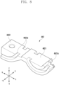
- FIG. 5A is a perspective view of a hinge bracket according to various embodiments of the disclosure.
- FIG. 5B is a plan view of a hinge bracket according to various embodiments of the disclosure.
- FIG. 5C is a sectional view of the hinge bracket viewed along line 5c-5cof FIG. 5B , according to various embodiments of the disclosure.
- FIG. 5D is a sectional view of the hinge bracket viewed along line 5d-5dof FIG. 5B according to various embodiments of the disclosure.
- the hinge bracket 410 may include a first rail receiving part (e.g., the first rail receiving part 411 in FIG. 4A ) disposed at one side of the folding axis (F) and configured to movably receive the first slide rail 421and a second rail receiving part 414 disposed on the other side thereof and configured to movably receive the second slide rail 422.
- the hinge bracket 410 may include a first receiving parts 412 disposed at the left and right side of the first rail receiving part 411 and configured to receive at least a part of the first rotator (e.g., the first rotator 431 in FIG.
- the hinge bracket 410 may include a third receiving part 413 configured to rotatably receive the first support rotator (e.g., the first support rotator 441 in FIG. 4A ) and a fourth receiving part 416 configured to rotatably receive the second support rotator (e.g., the second support rotator 442 in FIG. 4A ).
- the hinge bracket 410 may include a curved guide rib (e.g., the guide rib 4131 in FIG. 5C ) disposed in the third receiving part 413 and a curved guide rib (e.g., the guide rib 4161 in FIG. 5C ) disposed in the fourth receiving part 416.
- the second support rotator e.g., the second support rotator 442 in FIG. 8
- the hinge bracket 410 may be rotatably coupled to the hinge bracket 410 such that the guide rib 4161 is inserted into a guide rail (e.g., the guide rail 4421a in FIG. 8 ) disposed in the first rotation part (e.g., the first rotation part 4421 in FIG.
- the first support rotator (e.g., the first support rotator 441 in FIG. 4A ) may also be rotatably coupled to the hinge bracket 410 in substantially the same manner.
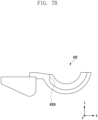
- FIG. 6A is a perspective view of a slide rail according to various embodiments of the disclosure.
- FIG. 6B is a sectional view of a slide rail viewed along line 6b-6b of FIG. 6A according to various embodiments of the disclosure.
- the second slide rail 422 may include a body 4221 and a guide groove 4222 formed from one side of the body 4221 to a designated length.
- the second slide rail 422 may include curved guide ribs 4223 disposed on both sides of the body 4221.
- the second slide rail 442 may be slidably coupled to the second rail receiving part(e.g., the second rail receiving part 414 in FIG. 5A ) of the hinge bracket 410 by fitting the guide groove 4222 around the second receiving part, and the curved guide rib 4223 may also be inserted into a guide rail (e.g., the guide rail 4323 in FIG.
- the second slide rail 422 may be coupled to the second rail receiving groove 414 of the hinge bracket 410 to be linearly reciprocatablewith respect thereto, and the second rotator 432 may be rotatably coupled to the second slide rail 422.
- the first slide rail e.g., the first slide rail 421 in FIG. 4A
- the first rotator e.g., the first rotator 431 in FIG. 4A
- the first slide rail 421 may also be coupled to each other in substantially the same manner.
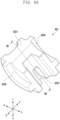
- FIG. 7A is a perspective view of a rotator according to various embodiments of the disclosure.
- FIG. 7B is a side view of a rotator according to various embodiments of the disclosure.
- the second rotator 432 may include a rotator body 4321 fixed to the second housing bracket (e.g., the second housing bracket 452 in FIG. 4A ) and a pair of rotation parts 4322 extending from the rotator body 4321 and spaced apart at a designated interval.
- the pair of rotation parts 4322 may be formed in a curved shape corresponding to the shape of the second slide rail (e.g., the second slide rail 422 in FIG. 6A ) and may include a curved guide rail 4323 configured to receive a guide rib (e.g., the guide rib 4223 in FIG. 6A ) formed on the second slide rail 422.
- the rotation part 4322 may include a catching ledge 4324 disposed on one end thereof such that the catching ledge 4324 is caught on the hinge bracket (e.g., the hinge bracket 410 in FIG. 5A ) when the second rotator 432 is rotated by a designated rotation amount, thereby limiting the rotation amount thereof.
- this rotation amount may be substantially the same as the rotation amount for the second housing 220 to transition from the folded state to the unfolded state.
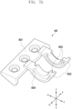
- FIG. 8 is a perspective view of a support rotator according to various embodiments of the disclosure.
- the second support rotator 442 may include a first rotation part 4421 and a second rotation part 4422 integrally formed with the first rotation part 4421.
- the first rotation part 4421 may include a guide rail 4421a for receiving a guide rib (e.g., the guide rib 4161 in FIG. 5C ) disposed in the fourth receiving part (e.g., the fourth receiving part 416 in FIG. 5A ) of the hinge bracket (e.g., the hinge bracket 410 in FIG. 5A ).
- the second rotation part 4422 may include a guide rail 4422a for receiving a guide rib (not numbered) disposed on a bracket rotationpart (e.g., the bracket rotation part 4522 in FIG. 4A ) of the second housing bracket (e.g., the second housing bracket 452 in FIG. 4A ). Therefore, the second support rotator 442 may be rotatably coupled to the hinge bracket 410 through the first rotation part 4421, and may be rotatably coupled to the second housing bracket 452 through the second rotation part 4422. Through the rotatable coupling through these two rotation parts 4421 and 4422, the second hinge plate (e.g., the second hinge plate 312 in FIG.
- the first support rotator (e.g., the first support rotator 441in FIG. 4A ) may be rotatably coupled to the hinge bracket 410 and the first housing bracket (e.g., the first housing bracket 451 in FIG. 4A ) in substantially the same manner.
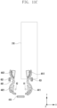
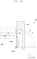
- FIG. 9A is a schematic configuration diagram of an electronic device in an unfolded state according to various embodiments of the disclosure.
- FIG. 9B is a configuration diagram of a hinge device in an unfolded state according to various embodiments of the disclosure.
- FIGS. 9C-9E show sectional views of the hinge device viewed along lines (a)-(a), (b)-(b), and (c)-(c) of FIG. 9B , respectively, in an unfolded state according to various embodiments of the disclosure.
- FIG. 9F is a view of area 9d of FIG. 9E ,illustrating a state in which a rotator and a slide rail are coupled to each other in an unfolded state according to various embodiments of the disclosure.
- FIG. 9G illustrates a rotational axis of a rotator in an unfolded state according to various embodiments of the disclosure.
- the first housing 210, the first hinge plate 311, the second hinge plate 312, and the second housing 220 may form the same plane, thereby supporting the rear surface of the flexible display 230.
- the first rotator 431 may be rotatably coupled to the first slide rail 421 slidably coupled to the hinge bracket 410, and the second rotator 432 may maintain in a state of being coupled to the second slide rail 422 linearly slidably coupled to the hinge bracket 410.
- the first slide rail 421 may be linearly slidably coupled to the hinge bracket 410.
- the first support plate 441 may maintain a state in which the first rotation part 4411 is rotatably coupled to the hinge bracket 410 and the second rotation part 4412 is rotatably coupled to the first housing bracket 451.
- the second support plate 442 may maintain a state in which the first rotation part 4421 is rotatably coupled to the hinge bracket 410 and the second rotation part 4422 is rotatably coupled to the second housing bracket 452.
- the first rotational axis(A1) of the first rotator 431 fixed through the first housing bracket 451 may be located at the first point (P1) near the rear surface of the flexible display 230.
- the second rotational axis(A2) of the second rotator 432 fixed through the second housing bracket 452 may also be located near the rear surface of the flexible display 230.
- Line (L1) represents a rotational trajectory formed bymovement of one end of the first housing 210 with respect to the first rotational axis(A1), in consideration of only the folding/unfolding operation of the first housing 210
- Line (L2) represents a rotational trajectory formed bymovement of one end of the first housing 210 to enable the folding area 230c of the flexible display 230 to be naturally folded into a waterdrop shape(e.g., to relieve the compressive force applied according to the folding operation of the flexible display).
- the line (L1) and the line (L2) may become coincident in the fully unfolded state, during transition from the unfolded state to the folded state, a gap between the line (L1) and line (L2)may gradually increase until adesignated intermediate folding angle (e.g.,an inflection angle) is formed, and then when completely folded from the designated intermediate folding angle, the line (L1) and the line (L2) may become coincident again while the gap therebetween is gradually decreasing.
- the designated folding angle may be about 45 degrees.However, without being limited thereto, the designated intermediate folding angle may be changed according to various shapes in which the folding area of the flexible display 230 is deformed in a folded state.
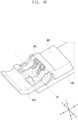
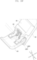
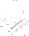
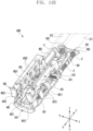
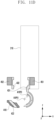
- FIG. 10A is a schematic configuration diagram of an electronic device in an intermediate state according to various embodiments of the disclosure.
- FIG. 10B is a configuration diagram of a hinge device in an intermediate state according to various embodiments of the disclosure.
- FIGS. 10C-10E show sectional views of the hinge device, viewed from positions corresponding to lines (a)-(a), (b)-(b), and (c)-(c) of FIG. 9B , respectively, in an intermediate state according to various embodiments of the disclosure.
- FIG. 10F is a view of area 10d of FIG. 10E ,illustrating a state in which a rotator and a slide rail are coupled to each other in an intermediate state according to various embodiments of the disclosure.
- FIG. 10G illustrates movement of a rotational axis of a rotator in an intermediate state according to various embodiments of the disclosure.
- the electronic device 200 may move in a direction in which the first housing 210 is folded, and may transition to an intermediate state having a designated intermediate folding angle ( ⁇ ).
- the first rotator 431 may also rotate about the first rotational axis (A1) along the first slide rail 421 rotatably coupled to the hinge bracket 410.
- the folding area 230c of the flexible display 230 may be subjected to compressive force while being folded into a waterdrop shape, and as a result, the first slide rail 421 may belinearly moved from the hinge bracket by a designated length.
- the first rotator 431 may rotate along the first slide rail 421, and at the same time, the first slide rail 421may linearly move along the first rail receiving part 411 of the hinge bracket 410.
- the first rotational axis(A1) may be moved from the first point (P1) to the second point (P2), so that the compressive force generated by the folding of the folding area of the flexible display 230 may berelieved.
- the second point (P2) of the first rotational axis(A1) may overlap the flexible display 230 or may be higher than the upper surface of the flexible display 230.
- the second rotational axis(A2) of the second rotator 432 may also be moved to another designated point through substantially the same operation.
- the designated intermediate folding angle ( ⁇ ) of the flexible display 230 when the designated intermediate folding angle ( ⁇ ) of the flexible display 230 is 45 degrees, the distance between the line (L1) and the line(L2)according to the rotational trajectory of the first housing 210 may be maximum.
- the intermediate folding angle ( ⁇ ) may be determined according to a bent shape of the folding area 230c of the flexible display 230.
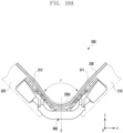
- FIG. 11A is a schematic configuration diagram of an electronic device in a folded state according to various embodiments of the disclosure.
- FIG. 11B is a configuration diagram of a hinge device in a folded state according to various embodiments of the disclosure.
- FIGS. 11C-11G show sectional views of the hinge device, viewed from positions corresponding to lines (a)-(a), (b)-(b), and (c)-(c) of FIG. 9B , respectively, in a folded state according to various embodiments of the disclosure.
- FIG. 11F illustrates a state in which a rotator and a slide rail in area 11d of FIG. 11E in a folded state according to various embodiments of the disclosure.
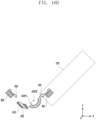
- FIG. 11G illustrates movement of a rotational axis of a rotator in a folded state according to various embodiments of the disclosure.
- the first rotator 431 may rotate about the first rotational axis (A1) along the first slide rail 421 rotatably coupled to the hinge bracket 410 according to the folding of the first housing 210.
- the compressive force applied to the folding area of the flexible display 230 may gradually decrease, and the first slide rail 421 may return to the original position thereof along the first rail receiving part 411 of the hinge bracket 410.
- the first rotator 431 may continuously rotate along the first slide rail 421, and at the same time, the first slide rail 421 may linearly move along the first rail receiving part 411 of the hinge bracket 410 to return to the original position thereof.
- the first rotating shaft (A1) may be moved from the second point (P2) to the first point (P1).
- the flexible display 230 may include a waterdrop shape formed through a folding area 230c and reverse bending areas 230d and 230e bent in the opposite direction to the folding area 230c, the folding area 230c being supported through the first and second hinge plates 311 and 312, and the reverse bending areas 230d and 230e being at positions corresponding to the boundary areas between the first and second hinge plates 311 and 312 and the first and second housings 210 and 220, respectively.
- compressive force to the flexible display 230 may repeatedly increase and decrease based on the designated intermediate folding angle ( ⁇ ) (e.g., about 45 degrees), and the compression forcemay be relieved by the movement of the first slide rail 421 and the second slide rail 422. Accordingly, buckling of the flexible display 230 that may occurduring operation may be advantageously reduced.
- ⁇ intermediate folding angle
- an electronic device may include a first housing (e.g., the first housing 210 in FIG. 1A ), a second housing (e.g., the second housing 220 in FIG. 1A ), a hinge device (e.g., the hinge device 400 in FIG. 4A ) configured to connect the first housing and the second housing to be foldable with respect to a folding axis (e.g., the folding axis (F) in FIG. 1A ), and a flexible display (e.g., the flexible display 230 in FIG.
- a first housing e.g., the first housing 210 in FIG. 1A
- a second housing e.g., the second housing 220 in FIG. 1A
- a hinge device e.g., the hinge device 400 in FIG. 4A
- a flexible display e.g., the flexible display 230 in FIG.
- the hinge device includes a hinge bracket (e.g., the hinge bracket 410 in FIG. 4A ), a first slide rail (e.g., the first slide 421 in FIG. 4A ) movably disposed at the hinge bracket and at one side of the folding axis, a second slide rail (e.g., the second slide rail 422 in FIG. 4A ) movably disposed at the hinge bracket and at the other side of the folding axis, a first rotator (e.g., the first rotator 431 in FIG.
- a hinge bracket e.g., the hinge bracket 410 in FIG. 4A
- a first slide rail e.g., the first slide 421 in FIG. 4A
- second slide rail e.g., the second slide rail 422 in FIG. 4A
- first slide rail and the second slide rail are moved with respect to the hinge bracket by a designated linear distance.
- the first rotator may be connected to the first housing and be configured to rotate around a first rotational axisrelative by the first slide rail
- the second rotator may be connected to the second housing and be configured to rotate around a second rotational axis by the second slide rail
- the first rotational axis may be moved by movement of the first slide rail
- the second rotational axis may be moved by movement of the second slide rail
- the first rotational axis may be located at the same point in the folded state and the unfolded state
- the second rotational axis may be located at the same point in the folded state and the unfolded state
- the first slide rail and the second slide rail may have a maximum linear movement distance at a designated intermediate folding angle.
- the designated intermediate folding angle may include 45 degrees.
- the intermediate folding angle may be determined according to a deformed shape of the folding area in the folded state.
- the first slide rail and/or the second slide rail may include a guide groove having a designated length and coupled to a rail receiving part disposed in the hinge bracket, such that the first slide rail and/or the second slide rail are linearly movable.
- the first rotator and/or the second rotator may include a curved rotation part
- the first slide rail and/or the second slide rail may include a curved guide rib disposed on an outer surface thereof, and the first rotator and/or the second rotator may be rotatably coupled by insertion of the guide rib into the guide rail.
- the electronic device may include a first support rotator having one end rotatably coupled to the hinge bracket and the other end rotatably coupled to the first rotator, and a second support rotator having one end rotatably coupled to the hinge bracket and the other end rotatably coupled to the second rotator.
- the electronic device may include a first hinge plate coupled to the first support rotator and a second hinge plate coupled to the second support rotator, wherein inthe unfolded state, the first housing, the first hinge plate, the second housing, and the second hinge plate form the same plane.
- the first housing and the first hinge plate in the folded state, may form different planes, and the second housing and the second hinge plate may form different planes.
- the electronic device may include a first housing bracket configured to fix the first rotator and the second housing, and a second housing bracket configured to fix the second rotator and the second housing, wherein the first support rotator is rotatably fixed to the first housing bracket, and the second support rotator is rotatably fixed to the second housing bracket.
- the folding area of the flexible display in the folded state, may be deformed into a waterdrop shape.
- the hinge device for a foldable electronic device (e.g., the electronic device 200 in FIG. 1A ) may include a hinge bracket (e.g., the hinge bracket 410 in FIG. 4A ), a first slide rail (e.g., the first slide 421 in FIG. 4A ) movably disposed at the hinge bracket and at one side of the folding axis, a second slide rail (e.g., the second slide rail 422 in FIG. 4A ) movably disposed at the hinge bracket and at the other side of the folding axis, a first rotator (e.g., the first rotator 431 in FIG.
- a hinge bracket e.g., the hinge bracket 410 in FIG. 4A
- a first slide rail e.g., the first slide 421 in FIG. 4A
- a second slide rail e.g., the second slide rail 422 in FIG. 4A
- a first rotator e.g., the first rotator 431 in FIG.
- first rotational axis e.g., the first rotational axis (A1) in FIG. 4B
- second rotator e.g., the second rotator 432 in FIG. 4A
- second rotational axis e.g., the second rotational axis (A2) in FIG. 4B
- the first slide rail and the second slide rail may be linearly moved.
- the first rotational axis may be located at the same point in the folded state and the unfolded state
- the second rotational axis may be located at the same point in the folded state and the unfolded state
- the first slide rail and the second slide rail may have a maximum linear movement distance at a designated intermediate folding angle.
- the intermediate folding angle may be determined according to a deformed shape of the folding area in the folded state.
- the first rotator and/or the second rotator may include a curved rotation part
- the first slide rail and/or the second slide rail may include a curved guide rib disposed on an outer surface thereof
- the first rotator and/or the second rotator may be rotatably coupled to the guide rib by insertion of the guide rib into the guide rail thereof.
- the electronic device may include a first support rotator having one end rotatably coupled to the hinge bracket and the other end rotatably coupled to the first rotator, and a second support rotator having one end rotatably coupled to the hinge bracket and the other end rotatably coupled to the second rotator.
Landscapes
- Engineering & Computer Science (AREA)
- Computer Hardware Design (AREA)
- Theoretical Computer Science (AREA)
- Physics & Mathematics (AREA)
- Human Computer Interaction (AREA)
- General Engineering & Computer Science (AREA)
- General Physics & Mathematics (AREA)
- Mathematical Physics (AREA)
- Signal Processing (AREA)
- Telephone Set Structure (AREA)
- Casings For Electric Apparatus (AREA)
Applications Claiming Priority (3)
| Application Number | Priority Date | Filing Date | Title |
|---|---|---|---|
| KR20220070866 | 2022-06-10 | ||
| KR1020220081425A KR20230170517A (ko) | 2022-06-10 | 2022-07-01 | 힌지 장치를 포함하는 전자 장치 |
| PCT/KR2023/006351 WO2023239065A1 (ko) | 2022-06-10 | 2023-05-10 | 힌지 장치를 포함하는 전자 장치 |
Publications (2)
| Publication Number | Publication Date |
|---|---|
| EP4482129A1 true EP4482129A1 (de) | 2024-12-25 |
| EP4482129A4 EP4482129A4 (de) | 2025-06-25 |
Family
ID=89118601
Family Applications (1)
| Application Number | Title | Priority Date | Filing Date |
|---|---|---|---|
| EP23820001.8A Pending EP4482129A4 (de) | 2022-06-10 | 2023-05-10 | Elektronische vorrichtung mit scharniervorrichtung |
Country Status (4)
| Country | Link |
|---|---|
| US (1) | US12578755B2 (de) |
| EP (1) | EP4482129A4 (de) |
| CN (1) | CN119301937A (de) |
| WO (1) | WO2023239065A1 (de) |
Families Citing this family (11)
| Publication number | Priority date | Publication date | Assignee | Title |
|---|---|---|---|---|
| EP4318181B1 (de) * | 2021-07-20 | 2025-09-17 | Samsung Electronics Co., Ltd. | Elektronische vorrichtung mit scharniermodul |
| CN116357660B (zh) * | 2022-07-06 | 2023-10-24 | 荣耀终端有限公司 | 一种同步机构、转轴机构和电子设备 |
| US20230093901A1 (en) * | 2022-10-28 | 2023-03-30 | Intel Corporation | Hinge for a foldable electronic device and related methods |
| TWI808037B (zh) * | 2022-11-10 | 2023-07-01 | 富世達股份有限公司 | 鉸鏈 |
| TWI835429B (zh) * | 2022-11-28 | 2024-03-11 | 富世達股份有限公司 | 鉸鏈 |
| CN116249328A (zh) * | 2023-03-13 | 2023-06-09 | 联想(北京)有限公司 | 一种导热元件以及电子设备 |
| USD1086119S1 (en) * | 2023-04-19 | 2025-07-29 | Samsung Electronics Co., Ltd. | Mobile electronic device |
| USD1082735S1 (en) * | 2023-04-19 | 2025-07-08 | Samsung Electronics Co., Ltd. | Mobile electronic device |
| US12360575B2 (en) * | 2023-07-27 | 2025-07-15 | Shin Zu Shing Co., Ltd. | Dual axis slider hinge |
| CN119641783A (zh) * | 2023-09-18 | 2025-03-18 | 富世达股份有限公司 | 铰链 |
| US12602090B2 (en) * | 2024-03-08 | 2026-04-14 | Google Llc | Support plate for folding portable display device |
Family Cites Families (22)
| Publication number | Priority date | Publication date | Assignee | Title |
|---|---|---|---|---|
| KR102178724B1 (ko) | 2014-02-17 | 2020-11-13 | 삼성전자주식회사 | 힌지유닛 및 이를 구비하는 접을 수 있는 디스플레이장치 |
| US20190227743A1 (en) | 2018-01-23 | 2019-07-25 | Micron Technology, Inc. | Identifying a read operation for a storage device based on a workload of a host system |
| CN111556931B (zh) * | 2018-04-17 | 2021-10-15 | 华为技术有限公司 | 开合机构及电子设备 |
| KR102444383B1 (ko) * | 2018-08-07 | 2022-09-16 | 후아웨이 테크놀러지 컴퍼니 리미티드 | 회전 샤프트 연결 구조체 및 절첩식 장치 |
| KR102233336B1 (ko) | 2018-08-14 | 2021-03-29 | 에이피시스템 주식회사 | 벤딩 장치 및 벤딩 방법 |
| US10469635B1 (en) | 2019-01-23 | 2019-11-05 | Motorola Mobility Llc | Hinged electronic device with chambers accommodating a dynamic flexible substrate and corresponding systems |
| KR102223632B1 (ko) * | 2019-03-13 | 2021-03-05 | 주식회사 에스코넥 | 플렉서블 디스플레이 패널에 설치되는 힌지장치 |
| CN111698355B (zh) | 2019-03-15 | 2021-07-09 | 华为技术有限公司 | 一种转轴机构及移动终端 |
| CN109992054B (zh) * | 2019-03-30 | 2021-04-13 | 联想(北京)有限公司 | 一种电子设备、连接装置 |
| KR20200139066A (ko) * | 2019-06-03 | 2020-12-11 | (주)에이유플렉스 | 탄성구동체 |
| US20220321685A1 (en) | 2019-06-03 | 2022-10-06 | Auflex Co., Ltd. | Elastic driving body |
| CN112153178A (zh) * | 2019-06-27 | 2020-12-29 | 华为技术有限公司 | 一种转轴机构及可折叠移动终端 |
| WO2021051124A1 (en) * | 2019-09-12 | 2021-03-18 | Google Llc | 2-axis soft hinge mechanism and foldable device having same |
| US11609606B2 (en) | 2019-10-14 | 2023-03-21 | Samsung Display Co., Ltd. | Display apparatus |
| KR20210063908A (ko) | 2019-11-25 | 2021-06-02 | 에이피시스템 주식회사 | 벤딩 장치 및 벤딩 방법 |
| KR102668216B1 (ko) * | 2019-12-02 | 2024-05-23 | 삼성전자주식회사 | 힌지 조립체를 포함하는 폴더블 전자 장치 |
| EP4411511B1 (de) * | 2019-12-13 | 2025-09-10 | Huawei Technologies Co., Ltd. | Drehwellenstruktur und elektronische vorrichtung |
| CN112995368B (zh) | 2019-12-13 | 2021-12-21 | 华为技术有限公司 | 一种铰链和移动终端 |
| KR102228223B1 (ko) | 2019-12-16 | 2021-03-18 | 주식회사 파인테크닉스 | 폴더블형 휴대 단말기 |
| KR102794424B1 (ko) | 2020-02-10 | 2025-04-11 | 삼성전자주식회사 | 힌지 구조물 및 이를 포함하는 폴더블 전자 장치 |
| KR102299989B1 (ko) | 2020-10-16 | 2021-09-08 | 이경희 | 플렉서블 디스플레이패널이 구성된 폴더블 디바이스의 힌지구조 |
| KR20220061651A (ko) * | 2020-11-06 | 2022-05-13 | 주식회사 파인테크닉스 | 폴더블 구조를 갖는 휴대단말기 힌지 |
-
2023
- 2023-05-10 WO PCT/KR2023/006351 patent/WO2023239065A1/ko not_active Ceased
- 2023-05-10 EP EP23820001.8A patent/EP4482129A4/de active Pending
- 2023-05-10 CN CN202380044107.3A patent/CN119301937A/zh active Pending
- 2023-06-09 US US18/208,121 patent/US12578755B2/en active Active
Also Published As
| Publication number | Publication date |
|---|---|
| US12578755B2 (en) | 2026-03-17 |
| CN119301937A (zh) | 2025-01-10 |
| EP4482129A4 (de) | 2025-06-25 |
| US20230409077A1 (en) | 2023-12-21 |
| WO2023239065A1 (ko) | 2023-12-14 |
Similar Documents
| Publication | Publication Date | Title |
|---|---|---|
| EP4482129A1 (de) | Elektronische vorrichtung mit scharniervorrichtung | |
| EP4310630A1 (de) | Faltbare elektronische vorrichtung mit anzeigeschutzstruktur | |
| US12108550B2 (en) | Electronic device including hinge module | |
| KR20230045899A (ko) | 디스플레이 보호 구조를 포함하는 폴더블 전자 장치 | |
| JP2023514892A (ja) | シーリング部材を含む電子装置 | |
| KR102902126B1 (ko) | 실링 부재를 포함하는 전자 장치 | |
| US20260075733A1 (en) | Hinge apparatus and electronic device including same | |
| US20250240902A1 (en) | Electronic device comprising hinge apparatus | |
| KR20240050193A (ko) | 힌지 장치를 포함하는 전자 장치 | |
| US20230371191A1 (en) | Electronic device including breakage prevention structure | |
| EP4446848A1 (de) | Elektronische vorrichtung mit scharniervorrichtung | |
| EP4507279A1 (de) | Flexible anzeige und elektronische vorrichtung mit der flexiblen anzeige | |
| KR20230170517A (ko) | 힌지 장치를 포함하는 전자 장치 | |
| US20250151216A1 (en) | Hinge apparatus and electronic device comprising same | |
| US20260086611A1 (en) | Hinge apparatus and electronic device comprising same | |
| KR20240011593A (ko) | 힌지 장치 및 힌지 장치를 포함하는 전자 장치 | |
| EP4685608A1 (de) | Elektronische vorrichtung mit scharniervorrichtung | |
| KR20240175652A (ko) | 힌지 장치 및 힌지 장치를 포함하는 전자 장치 | |
| EP4604682A1 (de) | Elektronische vorrichtung mit wasserdichter struktur | |
| US20260029823A1 (en) | Electric device including flexible display | |
| KR20250010482A (ko) | 힌지 장치를 포함하는 전자 장치 | |
| KR20240156911A (ko) | 힌지 장치를 포함하는 전자 장치 | |
| KR20240178166A (ko) | 힌지 장치 및 힌지 장치를 포함하는 전자 장치 | |
| KR20240081243A (ko) | 방수 구조를 포함하는 전자 장치 | |
| CN119908108A (zh) | 包括柔性印刷电路板的电子装置 |
Legal Events
| Date | Code | Title | Description |
|---|---|---|---|
| STAA | Information on the status of an ep patent application or granted ep patent |
Free format text: STATUS: THE INTERNATIONAL PUBLICATION HAS BEEN MADE |
|
| PUAI | Public reference made under article 153(3) epc to a published international application that has entered the european phase |
Free format text: ORIGINAL CODE: 0009012 |
|
| STAA | Information on the status of an ep patent application or granted ep patent |
Free format text: STATUS: REQUEST FOR EXAMINATION WAS MADE |
|
| 17P | Request for examination filed |
Effective date: 20240920 |
|
| AK | Designated contracting states |
Kind code of ref document: A1 Designated state(s): AL AT BE BG CH CY CZ DE DK EE ES FI FR GB GR HR HU IE IS IT LI LT LU LV MC ME MK MT NL NO PL PT RO RS SE SI SK SM TR |
|
| A4 | Supplementary search report drawn up and despatched |
Effective date: 20250528 |
|
| RIC1 | Information provided on ipc code assigned before grant |
Ipc: G06F 1/16 20060101ALI20250522BHEP Ipc: F16C 11/04 20060101ALI20250522BHEP Ipc: H04M 1/02 20060101AFI20250522BHEP |
|
| DAV | Request for validation of the european patent (deleted) | ||
| DAX | Request for extension of the european patent (deleted) | ||
| GRAP | Despatch of communication of intention to grant a patent |
Free format text: ORIGINAL CODE: EPIDOSNIGR1 |
|
| STAA | Information on the status of an ep patent application or granted ep patent |
Free format text: STATUS: GRANT OF PATENT IS INTENDED |
|
| INTG | Intention to grant announced |
Effective date: 20260126 |