EP4481784A1 - Parallel schaltender lastschalter und mittelspannungsschaltanlage damit - Google Patents
Parallel schaltender lastschalter und mittelspannungsschaltanlage damit Download PDFInfo
- Publication number
- EP4481784A1 EP4481784A1 EP24183100.7A EP24183100A EP4481784A1 EP 4481784 A1 EP4481784 A1 EP 4481784A1 EP 24183100 A EP24183100 A EP 24183100A EP 4481784 A1 EP4481784 A1 EP 4481784A1
- Authority
- EP
- European Patent Office
- Prior art keywords
- contact
- moving
- cam
- breaking load
- load switch
- Prior art date
- Legal status (The legal status is an assumption and is not a legal conclusion. Google has not performed a legal analysis and makes no representation as to the accuracy of the status listed.)
- Pending
Links
Images


Classifications
-
- H—ELECTRICITY
- H01—ELECTRIC ELEMENTS
- H01H—ELECTRIC SWITCHES; RELAYS; SELECTORS; EMERGENCY PROTECTIVE DEVICES
- H01H31/00—Air-break switches for high tension without arc-extinguishing or arc-preventing means
- H01H31/003—Earthing switches
-
- H—ELECTRICITY
- H01—ELECTRIC ELEMENTS
- H01H—ELECTRIC SWITCHES; RELAYS; SELECTORS; EMERGENCY PROTECTIVE DEVICES
- H01H33/00—High-tension or heavy-current switches with arc-extinguishing or arc-preventing means
- H01H33/60—Switches wherein the means for extinguishing or preventing the arc do not include separate means for obtaining or increasing flow of arc-extinguishing fluid
- H01H33/66—Vacuum switches
- H01H33/664—Contacts; Arc-extinguishing means, e.g. arcing rings
- H01H33/6647—Contacts; Arc-extinguishing means, e.g. arcing rings having fixed middle contact and two movable contacts
-
- H—ELECTRICITY
- H01—ELECTRIC ELEMENTS
- H01H—ELECTRIC SWITCHES; RELAYS; SELECTORS; EMERGENCY PROTECTIVE DEVICES
- H01H33/00—High-tension or heavy-current switches with arc-extinguishing or arc-preventing means
- H01H33/60—Switches wherein the means for extinguishing or preventing the arc do not include separate means for obtaining or increasing flow of arc-extinguishing fluid
- H01H33/66—Vacuum switches
- H01H33/662—Housings or protective screens
- H01H33/66261—Specific screen details, e.g. mounting, materials, multiple screens or specific electrical field considerations
-
- H—ELECTRICITY
- H01—ELECTRIC ELEMENTS
- H01H—ELECTRIC SWITCHES; RELAYS; SELECTORS; EMERGENCY PROTECTIVE DEVICES
- H01H33/00—High-tension or heavy-current switches with arc-extinguishing or arc-preventing means
- H01H33/60—Switches wherein the means for extinguishing or preventing the arc do not include separate means for obtaining or increasing flow of arc-extinguishing fluid
- H01H33/66—Vacuum switches
- H01H33/666—Operating arrangements
- H01H33/6661—Combination with other type of switch, e.g. for load break switches
-
- H—ELECTRICITY
- H01—ELECTRIC ELEMENTS
- H01H—ELECTRIC SWITCHES; RELAYS; SELECTORS; EMERGENCY PROTECTIVE DEVICES
- H01H3/00—Mechanisms for operating contacts
- H01H3/32—Driving mechanisms, i.e. for transmitting driving force to the contacts
- H01H3/42—Driving mechanisms, i.e. for transmitting driving force to the contacts using cam or eccentric
-
- H—ELECTRICITY
- H01—ELECTRIC ELEMENTS
- H01H—ELECTRIC SWITCHES; RELAYS; SELECTORS; EMERGENCY PROTECTIVE DEVICES
- H01H31/00—Air-break switches for high tension without arc-extinguishing or arc-preventing means
- H01H31/26—Air-break switches for high tension without arc-extinguishing or arc-preventing means with movable contact that remains electrically connected to one line in open position of switch
- H01H31/28—Air-break switches for high tension without arc-extinguishing or arc-preventing means with movable contact that remains electrically connected to one line in open position of switch with angularly-movable contact
Definitions
- circuit breakers and disconnect switches in medium-voltage or high-voltage power lines or power cables usually include boxes in which switch contacts re arranged so as to move between a position of contact with each other corresponding to closure of the power line and a position of separation from each other corresponding to disconnection of the power line.
- These boxes are filled with a dielectric fluid; the switch contacts are immersed in the dielectric fluid, and the dielectric fluid assists in disconnecting current by extinguishing arc that may remain after the switch contacts are separated from each other.
- a lot of different fluids (such as air, oil, nitrogen, etc.) were proposed in the past, but sulfur hexafluoride (SF6) is commonly used now, which has good dielectric characteristics and is therefore very suitable for the purpose.
- the vacuum interrupter is arranged in a bypass circuit parallel to a main circuit of a main switch including one phase of the electrical equipment.
- no current passes through the vacuum interrupter during normal operation, that is, when the main switch is closed and thus the current passes through the main circuit.
- a movable portion of the main switch closes the parallel bypass circuit containing the vacuum interrupter before the current in the main circuit is interrupted. The current is then interrupted in the main circuit, so that all the current then passes through the vacuum interrupter.
- the movable portion of the main switch disconnects the contact of the vacuum interrupter, and the current is cut off. Therefore, the generation of arcs in the main switch is avoided, because at the moment of cutting off the current, the current only passes through the vacuum interrupter. Because there is current passing through the vacuum interrupter only during a transient phase of the cut-off current, the vacuum interrupter can be simplified and be smaller in size than the vacuum interrupters normally intended to be arranged in series with the main switch.
- the disconnection of the vacuum interrupter is only caused by the main switch in the disconnection stroke. Therefore, the relative arrangement of the vacuum interrupter and the main switch is limited. Furthermore, the kinematic connection between the vacuum interrupter and the main switch needs to be very precise. In view of the number of elements involved in the assembly, the dimensional tolerances of each element of the kinematic connection sequence must be tight.
- a task of present disclosure is to provide a parallel breaking load switch to overcome the defects in the prior art.
- a parallel breaking load switch which is suitable for breaking a power line of a medium-voltage electrical system, and includes: a stationary contact including a first end connected to the power line and a second end opposite to the first end; a moving contact, wherein the moving contact is configured to be capable of rotating around a pivot axis among a closed position, a commutation position and a breaking position, the moving contact is connected to the second end of the stationary contact at the closed position and electrically communicated with the stationary contact, and the moving contact is disconnected from the stationary contact when rotating around the pivot axis to the breaking position; a vacuum interrupter with a fixed switch contact and a movable switch contact arranged therein, wherein the stationary contact is electrically connected with the fixed switch contact; and a cam assembly, wherein the cam assembly is provided with a small contact capable of rotating around the rotating axis, the small contact is provided with an electric conductor that can be electrically connected with the moving contact so as to be electrically connected with the vacuum interrupt
- the parallel breaking load switch of present disclosure the technical demand of lower precision, longer breaking distance and capability of flexibly setting over-travel can be allowed in a simple and reliable manner when the moving part contributing to the disconnection of the vacuum interrupter. Moreover, the parallel breaking load switch according to present disclosure needs fewer components and less cost and has good reliability.
- the cam assembly includes a cam frame, wherein the small contact is pivotally connected to the cam frame, and the cam frame is provided with a leading groove for leading the moving end of the movable switch contact to move linearly between the off position and the on position; a cam pivotally connected to the cam frame, wherein the cam is provided with an abutting pin operatively connected with the small contact and a guiding groove for sandwiching the moving end of the movable switch contact; wherein the small contact can drive the cam to pivot together around the rotating axis, so that the moving end of the movable switch contact moves linearly between the off position and the on position via the leading groove and the guiding groove.
- the small contact is designed as an elongated piece, which includes a first end pivoted to the cam frame and a second end being opposite to the first end, wherein the second end is provided with an elastic sheet capable of elastically abutting the moving contact.
- the parallel breaking load switch further includes an insulation bracket constructed as an integral piece and includes a horizontal portion for fixedly installing the cam frame and the vacuum interrupter and a vertical portion for fixedly installing the stationary contact.
- the cam assembly further includes a torsional spring fixedly installed to the cam frame, wherein a supporting leg of the torsional spring operatively abuts the cam to pivot along with the cam relative to the cam frame to accumulate elastic potential energy, and to subsequently release the elastic potential energy so as to return the cam to an initial position.
- the moving contact includes a pair of spaced contact pieces, wherein one end of the contact piece is provided with a spherical portion protruded outwards and operatively connected to an actuator so as to be actuated to rotate around the pivot axis among the closed position, the commutation position and the breaking position, and the other end of the contact piece is provided with an abutting portion that is protruded outwards and forms surface contact with the second end of the stationary contact.
- the parallel breaking load switch further includes a voltage equalizing ring arranged adjacent to the spherical portion of the contact piece and used for equalizing an electric field of the current flowing through the moving contact, and a semicircular shielding cover arranged adjacent to the abutting portion of the contact piece in a spaced manner and used for preventing partial discharge.
- the small contact is made of an insulation material, and the second end is provided with an insulation material layer at one side opposite to the contact piece.
- the parallel breaking load switch further includes a grounding contact located at one side of the moving contact and capable of being electrically coupled to a grounding conductor, wherein the grounding contact is designed generally in a U shape and includes a first end coupled to the grounding conductor, a second end opposite to the first end and a hollow portion located between the first end and the second end, and the second end is provided with a pair of contact feet matched with the moving contact.
- a medium-voltage switchgear which includes a shell filled with insulation gas and the parallel breaking load switch arranged in the shell.
- a medium-voltage switchgear according to present disclosure is particularly suitable for being connected into a medium-voltage circuit as a load breaking switch. Therefore, the medium-voltage switchgear is used to provide a breaking function and a circuit cutoff function at a specified circuit state (a nominal or overload state), and particularly to make a load-side portion of the circuit to be grounded.
- a specified circuit state a nominal or overload state
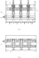
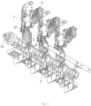
- the medium-voltage switchgear belongs to a multi-phase (e.g. three-phase) type, and includes a plurality of (e.g. three) electrodes.
- the medium-voltage switchgear includes a shell C preferably made of an insulation material, and the insulation shell C beneficially defines an internal space capable of accommodating the electrodes.
- the insulation shell C has an elongated shape (for example, generally a cuboid shape) extending along a main longitudinal axis.
- the plurality of electrodes are arranged side by side along a corresponding horizontal plane perpendicular to the main longitudinal axis of the medium-voltage switchgear.
- the internal space of the medium-voltage switchgear is filled with pressurized dry air with low environment impact or another insulation gas (such as a mixture of oxygen, nitrogen, carbon dioxide and/or fluorinated gases).
- each electrode is electrically connected to a power line of the medium-voltage electrical system and is correspondingly broken by a parallel breaking load switch of present disclosure
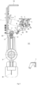
- the parallel breaking load switch 100 includes a stationary contact 1 which includes a first end 11 connected to the power line and a second end 12 opposite to the first end, the first end 11 is protruded out of the upper side of the insulation shell C and provided with a connector connected with an external power line, and the second end 12 is a flaky piece arranged inside the insulation shell C and protruded inwards.
- the stationary contact 1 can be realized according to other solutions of a known type (for example, configured according to a plurality of blades including a plurality of fixed contact pieces), which is not described in detail here for brevity.
- the parallel breaking load switch 100 further includes a moving contact 2 which is at least partially made of a conductive material, and can be electrically connected to the power line of the electrical system via a wiring terminal 25 located at the lower end.
- the moving contact 2 can pivot reciprocally around a corresponding pivot axis A2 generally parallel to the main longitudinal axis of the medium-voltage switchgear.
- the moving contact 2 can rotate in a first rotating direction away from the second end 12 of the stationary contact 1 and toward a grounding contact 3 or a second rotating direction, and tire second rotating direction is opposite to the first rotating direction and is directed away from the grounding contact 3 and towards the second end 12 of the stationary contact 1.
- the moving contact 2 moves in the first rotating direction during the breaking operation and commutation operation of the medium-voltage switchgear and moves in the second rotating direction during the closing operation or reconnection of the switchgear.
- the moving contact 2 can move reciprocally around the pivot axis A2, so that the moving contact 2 can be electrically connected to the second end 12 of the stationary contact 1 or separated from the second end 12 of the stationary contact 1, or can be electrically connected to the grounding contact 3 or separated from the grounding contact 3.
- the moving contact 2 can be formed by a pair of spaced contact pieces that are made of a conductive material. Each contact piece has an end that is hinged to the corresponding wiring terminal 25 at the pivot axis A2 and forms an opposite free end electrically coupled with the second end 12 of the stationary contact 1.
- the medium-voltage switchgear includes an actuator 21, and the actuator 21 provides an appropriate actuating force to actuate the moving contact 2 ( Figure 1 ).
- the actuator 21 here can be, for example, a mechanical actuator, an electric motor or a solenoid actuator.
- one end of the contact piece of the moving contact 2 is provided with a spherical portion protruded outwards and operatively connected to the actuator 21 so as to be actuated to rotate around the pivot axis A2 among the closed position, the commutation position and the breaking position that are described in detail below, and the other end of the contact piece of the moving contact 2 is provided with an abutting portion 22 protruded outwards and capable of forming surface contact with the second end 12 of the stationary contact 1.
- a contact area between the moving contact 2 and the stationary contact 1 can be increased obviously, thereby improving the passing capacity of the current, so that ablation and fusion welding are unlikely to occur when the breaking operation is performed by means of the moving contact 2.
- the lower portion of the moving contact 2 is designed in a spherical surface, the friction or resistance of the pivot movement can be reduced, thereby meeting the requirements of temperature-rise test.
- the moving contact 2 is also provided with a voltage equalizing ring 24 arranged adjacent to the spherical portion of the contact piece and used to equalize an electric field of electrical current flowing through the moving contact and a semicircular shielding cover 23 arranged adjacent to the abutting portion of the contact piece at an interval and used for preventing partial discharge, which are helpful to prevent the partial discharge during the normal operation of the medium-voltage electrical equipment and equalize the electric field inside the electrical equipment, and beneficial to improving the operation reliability and service life of the medium-voltage electrical equipment.
- the medium-voltage electrical equipment can also include a grounding contact 3 located at one side of the moving contact 2 and capable of being electrically coupled to a grounding conductor, wherein the grounding contact 3 is designed generally in a U shape and includes a first end coupled to a grounding conductor, a second end opposite to the first end and a hollow portion located between the first end and the second end, and the second end is provided with a pair of contact feet 31 (referring to Figures 8-10 ) matched with the moving contact.
- grounding contact 3 is designed in a U shape, those skilled in the art may know that two sides of an electrodynamic force are opposite in direction according to a right-hand rule, and most of electrodynamic force acting on the moving contact 3 can be counteracted, so that the grounding closing test is more stable and more reliable.
- the parallel breaking load switch 100 also includes a vacuum interrupter 4, which is provided with a fixed switch contact and a movable switch contact, and the stationary contact 1 is electrically connected with the fixed switch contact.
- the vacuum interrupter 4 as an example here includes the paired fixed switch contact and movable switch contact, wherein the fixed switch contact can be electrically connected with the first end 11 of the stationary contact 1, and the vacuum interrupter 4 is fixedly connected to the stationary contact 1.
- the movable switch contact is driven by a moving end 42 extending from the shell of the vacuum interrupter 4.
- the medium-voltage electrical equipment does not use sulfur hexafluoride (SF6) gas as an insulation medium, but uses other gases with poorer insulation properties, higher requirements are imposed on the breaking distance of the arc interrupter and the kinematic connection between components of the load switch, and further description is made below in combination with the accompanying drawings.
- SF6 sulfur hexafluoride
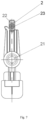
- the parallel breaking load switch 100 includes a cam assembly, wherein the cam assembly is provided with a small contact 7 capable of rotating around a rotating axis A1, and the small contact 7 is provided with an electric conductor 6 capable of being electrically connected with the moving contact 2 so as to be electrically connected with the vacuum interrupter 4 in response to the rotation of the moving contact 2 around the pivot axis A2.
- the cam assembly includes a cam frame 5, wherein the small contact 7 is pivotally connected to the cam frame 5 via, for example, a pivot point 52 of a pivot pin, the cam frame 5 is provided with a leading groove 51 for leading the moving end 42 of the movable switch contact to move linearly between an off position and an on position; the cam assembly also includes a cam 8 capable of being pivotally connected to the cam frame 5, the cam 8 is designed generally in a semilunar shape and also pivotally pivoted to the pivot point 52 by means of the pivot pin, the cam 8 is provided with an abutting pin 82 operatively connected with the small contact 7 and a guiding groove 81 sandwiching the moving end 42 of the movable switch contact; therefore, when the small contact 7 drives the cam 8 to pivot together around the rotating axis A1, the moving end 42 of the movable switch contact can move linearly between the off position and the on position via the leading groove 81 and the guiding groove 51; and the moving end 42 of the movable switch contact is aligned with the
- the cam assembly described above realizes the breaking of the vacuum interrupter 4 in a manner of rotating the small contact 7 that can be used as a lever.
- the whole process is consisting of following transmissions, i.e. rotation pair realized by the moving contact 2, the lever realized by the small contact 7, the movement synthesis of the guiding groove 81 and the leading groove 51.
- a contact angle of the moving contact 2 and the breaking stroke of the vacuum interrupter 4 can be controlled not to be less than 7 mm, and can over-travel can also be set by lengths of the guiding groove 81 in the cam 8 and the leading groove 51 in the cam frame 5 and interaction thereof and the length of the arm of force of the small contact 7.
- the cam assembly further includes a torsional spring 9 fixedly installed to the cam frame 5, wherein a supporting leg of the torsional spring 9 operatively abuts the cam 8 so as to pivot along with the cam 8 relative to the cam frame 5 to accumulate elastic potential energy, and subsequently to release the elastic potential energy to return the cam 8 to the initial position; and thus, when the cam 8 rotates clockwise or counterclockwise, the cam can be reset rapidly under the action of the torsional spring 9.
- the small contact 7 is designed as an elongated piece, which includes a first end pivoted to the cam frame 5 and a second end opposite to the first end, wherein the second end is provided with an elastic sheet 71 elastically abutting the moving contact 2; the elastic sheet 71 is designed to expand outwards here and located at the top of the second end of the small contact 7; and when the moving contact 2 performs the breaking operation around the pivot axis A2, the elastic sheet 71 can be snapped into the inner sides of two contact pieces of the moving contact 2.
- the design ensures the continuity of the eletrical current.
- a copper sheet 73 electrically communicated with the electric conductor 6 is also arranged below the elastic sheet 71; the moving contact 2 may contact the copper sheet 73 when continuing the action; the current is transferred to the vacuum interrupter 4 through the copper sheet 73 and the electric conductor 6; and the above design can realize a simple bypass circuit.
- the small contact 7 is preferably made of insulation material and the second end of the small contact is provided with an insulation material layer on the side opposite to the elastic sheet 71.
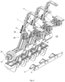
- the parallel breaking load switch 100 also includes an insulation bracket 10 constructed as an integral piece and includes a horizontal portion 10B for fixedly installing the cam frame 5 and the vacuum interrupter 4 and a vertical portion 10A for fixedly installing the stationary contact 1; and the insulation bracket 10 is injection molded by high-strength PC material, and three phases are installed in a same plane. After the vacuum interrupter 4 and the stationary contact 1 are installed, the cam assembly and the stationary contact 1 can be installed on the same insulation bracket 10, so that the transmission precision can be ensured, and the assembling errors can be reduced effectively.
- the horizontal portion 10B of the insulation bracket 10 can also be fixedly provided with a lead holder 53, wherein as best shown in Figure 6 , the lead holder 53 is provided with a horizontal installation section installed to the plane below the horizontal portion 10B and an arc section for leading the electric conductor 6, thereby presenting a mirrored "5" shape in a cross section.
- a groove for embedding the electric conductor 6 is arranged in the arc section, at the installed state, and the electric conductor moves in an arc path defined by the groove in the arc section, which effectively prevents the electric conductor 6 from being broken due to repeated bending, affecting the reliability and service life of the whole parallel breaking load switch 100.
- the parallel breaking load switch 100 can execute different types of operations, and each of the operations corresponds to given change in the operation state. Specifically, as shown in Figure 8 , the moving contact 2 is located on the closed position, the vacuum interrupter 4 then is located on a default closed position, that is, the fixed switch contact and the movable switch contact are closed. When the moving contact 2 is located at the closed position, the moving contact 2 is kept in close contact with the second end 12 of the stationary contact 1 by means of the abutting portion 22, the current can flow from the first end of the stationary contact 1 to the stationary contact and further flows through the moving contact 2 to reach the wiring terminal 25, and the parallel breaking load switch 100 can be considered to be in closed configuration.
- the moving contact 2 begins to rotate around the pivot axis A2 and contacts the second end of the stationary contact 1 and the cam assembly (specifically the small contact 7 in the cam assembly) connected with the vacuum interrupter 4 at a certain rotation point, thus forming a commutation point, wherein since the fixed switch contact and the movable switch contact of the vacuum interrupter 4 are closed, a bypass current circuit from the first end 11 of the stationary contact 1 to the moving contact 2 directly through the vacuum interrupter 4 and the electric conductor 6 is thus formed.
- the parallel breaking load switch 100 is considered to be in the commutation configuration.
- the moving contact 2 continues to rotate around the pivot axis A2 under the action of the actuator 21 and thus is separated from the second end 12 of the stationary contact 1 but kept in electric contact with the small contact 7; and moreover, the fixed switch contact and the movable switch contact of the vacuum interrupter 4 still contact each other, so that the current flows to the vacuum interrupter 4 only from the first end 11 of the stationary contact 1 and then flows to the moving contact 2 through the vacuum interrupter 4.
- the moving contact 2 keeps rotating, and during the rotation of the moving contact, the small contact 7 continues to rotate correspondingly, the cam 8 is then driven by the abutting pin 82 to rotate together relative to the cam frame 5 with the pivot point 52 as the rotating axis A1, and consequently, with the rotation of the cam assembly, the moving end 42 of the movable switch contact accommodated in the leading groove 51 and the guiding groove 81 of the cam assembly moves linearly along the axis of the vacuum interrupter 4 from the on position to the off position so as to separate the movable switch contact from the fixed switch contact of the vacuum interrupter 4, and the stroke of the linear movement is not less than 7 mm.
- the result is that the contact of the vacuum interrupter 4 is already broken to cut off the current.
- the moving contact 2 continues to rotate and passes through the small contact 7, the small contact 7 is then reset under the action of the torsional spring 9 and drives the vacuum interrupter 4 to be returned to the default closed configuration; however, the moving contact 2 is already separated from the small contact 7 and the first end 12 of the stationary contact 1; therefore, the parallel breaking load switch 100 is already in the breaking configuration; and as the moving contact rotates to contact the grounding contact 3 and is stopped by the grounding contact, the parallel breaking load switch 100 is then in the grounding configuration.
- the parallel breaking load switch 100 can be changed from grounding configuration to closed configuration; moreover, a current path is formed between the second end 11 of the stationary contact 1 and the moving contact 2; and moreover, the vacuum interrupter 4 is configured in a state that the contact is closed, and there is no current flowing through the vacuum interrupter. Thereafter, the parallel breaking load switch 100 is prepared for another breaking operation. Since the opposite side of the small contact 7 is designed to be insulated, the moving contact 2 is prevented from switching on the bypass circuit when pivoting to the closed position in an opposite direction.
Landscapes
- High-Tension Arc-Extinguishing Switches Without Spraying Means (AREA)
Applications Claiming Priority (1)
| Application Number | Priority Date | Filing Date | Title |
|---|---|---|---|
| CN202321592062.7U CN220358020U (zh) | 2023-06-21 | 2023-06-21 | 并联开断负荷开关及具有其的中压开关设备 |
Publications (1)
| Publication Number | Publication Date |
|---|---|
| EP4481784A1 true EP4481784A1 (de) | 2024-12-25 |
Family
ID=89506039
Family Applications (1)
| Application Number | Title | Priority Date | Filing Date |
|---|---|---|---|
| EP24183100.7A Pending EP4481784A1 (de) | 2023-06-21 | 2024-06-19 | Parallel schaltender lastschalter und mittelspannungsschaltanlage damit |
Country Status (4)
| Country | Link |
|---|---|
| EP (1) | EP4481784A1 (de) |
| JP (1) | JP2025011037A (de) |
| KR (1) | KR20240178238A (de) |
| CN (1) | CN220358020U (de) |
Families Citing this family (1)
| Publication number | Priority date | Publication date | Assignee | Title |
|---|---|---|---|---|
| CN119132849B (zh) * | 2024-11-12 | 2025-04-18 | 广东正超电气有限公司 | 一种环保型负荷开关柜并联式开断装置 |
Citations (3)
| Publication number | Priority date | Publication date | Assignee | Title |
|---|---|---|---|---|
| CN102623234A (zh) | 2011-01-25 | 2012-08-01 | 施耐德电器工业公司 | 包括真空盒的中压开关装置 |
| EP2845213B1 (de) * | 2012-06-25 | 2016-08-03 | Siemens Aktiengesellschaft | Dreistellungslasttrennschalter für mittelspannungs-schaltanlagen |
| CA3136763A1 (en) * | 2021-03-03 | 2022-09-03 | Abb Schweiz Ag | A medium voltage switching apparatus |
-
2023
- 2023-06-21 CN CN202321592062.7U patent/CN220358020U/zh active Active
-
2024
- 2024-06-19 EP EP24183100.7A patent/EP4481784A1/de active Pending
- 2024-06-21 KR KR1020240081128A patent/KR20240178238A/ko active Pending
- 2024-06-21 JP JP2024100689A patent/JP2025011037A/ja active Pending
Patent Citations (4)
| Publication number | Priority date | Publication date | Assignee | Title |
|---|---|---|---|---|
| CN102623234A (zh) | 2011-01-25 | 2012-08-01 | 施耐德电器工业公司 | 包括真空盒的中压开关装置 |
| US9058948B2 (en) * | 2011-01-25 | 2015-06-16 | Schneider Electric Industries Sas | Medium-voltage switchgear device comprising a vacuum cartridge |
| EP2845213B1 (de) * | 2012-06-25 | 2016-08-03 | Siemens Aktiengesellschaft | Dreistellungslasttrennschalter für mittelspannungs-schaltanlagen |
| CA3136763A1 (en) * | 2021-03-03 | 2022-09-03 | Abb Schweiz Ag | A medium voltage switching apparatus |
Also Published As
| Publication number | Publication date |
|---|---|
| KR20240178238A (ko) | 2024-12-30 |
| CN220358020U (zh) | 2024-01-16 |
| JP2025011037A (ja) | 2025-01-23 |
Similar Documents
| Publication | Publication Date | Title |
|---|---|---|
| US7829814B2 (en) | Vacuum circuit interrupter grounding assembly | |
| US8779318B2 (en) | Switching device and a switchgear | |
| CN115036171A (zh) | 中压开关装置 | |
| KR20140019022A (ko) | 스위칭 디바이스 및 개폐기 | |
| US11776779B2 (en) | Medium voltage switching apparatus | |
| KR20140021703A (ko) | 스위칭 디바이스 및 개폐기 | |
| US20120181156A1 (en) | Gas-insulated high-voltage switching system | |
| EP4481784A1 (de) | Parallel schaltender lastschalter und mittelspannungsschaltanlage damit | |
| US12444559B2 (en) | Medium voltage switching apparatus | |
| US12087527B2 (en) | Switching device on an electric line comprising a vacuum interrupter | |
| EP4276872A1 (de) | Mittelspannungsschaltvorrichtung | |
| EP4277059A1 (de) | Schaltanlagen für elektrische stromverteilungsnetze | |
| KR20010106810A (ko) | 가스절연 개폐기의 단로기 | |
| EP4459653B1 (de) | Schaltvorrichtung für elektrische systeme | |
| EP4030455A1 (de) | Mittelspannungsschaltvorrichtung | |
| US12293888B2 (en) | Medium voltage switching apparatus | |
| EP4089704B1 (de) | Mittelspannungsschaltvorrichtung | |
| EP4283645B1 (de) | Mittelspannungsschaltvorrichtung | |
| KR101164028B1 (ko) | 가스절연 개폐장치 | |
| CN121034898A (zh) | 一种真空断路器以及隔离开关 | |
| CN120709100A (zh) | 三相共箱式快速接地开关、气体绝缘金属封闭开关设备 | |
| CN120954919A (zh) | 一种隔离开关以及电气设备 |
Legal Events
| Date | Code | Title | Description |
|---|---|---|---|
| PUAI | Public reference made under article 153(3) epc to a published international application that has entered the european phase |
Free format text: ORIGINAL CODE: 0009012 |
|
| STAA | Information on the status of an ep patent application or granted ep patent |
Free format text: STATUS: THE APPLICATION HAS BEEN PUBLISHED |
|
| AK | Designated contracting states |
Kind code of ref document: A1 Designated state(s): AL AT BE BG CH CY CZ DE DK EE ES FI FR GB GR HR HU IE IS IT LI LT LU LV MC ME MK MT NL NO PL PT RO RS SE SI SK SM TR |
|
| STAA | Information on the status of an ep patent application or granted ep patent |
Free format text: STATUS: REQUEST FOR EXAMINATION WAS MADE |
|
| 17P | Request for examination filed |
Effective date: 20250612 |
|
| GRAP | Despatch of communication of intention to grant a patent |
Free format text: ORIGINAL CODE: EPIDOSNIGR1 |
|
| STAA | Information on the status of an ep patent application or granted ep patent |
Free format text: STATUS: GRANT OF PATENT IS INTENDED |
|
| INTG | Intention to grant announced |
Effective date: 20250904 |