EP4481265A1 - Planar illumination device - Google Patents
Planar illumination device Download PDFInfo
- Publication number
- EP4481265A1 EP4481265A1 EP22927382.6A EP22927382A EP4481265A1 EP 4481265 A1 EP4481265 A1 EP 4481265A1 EP 22927382 A EP22927382 A EP 22927382A EP 4481265 A1 EP4481265 A1 EP 4481265A1
- Authority
- EP
- European Patent Office
- Prior art keywords
- light
- disposed
- illumination device
- light sources
- field lens
- Prior art date
- Legal status (The legal status is an assumption and is not a legal conclusion. Google has not performed a legal analysis and makes no representation as to the accuracy of the status listed.)
- Pending
Links
Images




Classifications
-
- G—PHYSICS
- G02—OPTICS
- G02F—OPTICAL DEVICES OR ARRANGEMENTS FOR THE CONTROL OF LIGHT BY MODIFICATION OF THE OPTICAL PROPERTIES OF THE MEDIA OF THE ELEMENTS INVOLVED THEREIN; NON-LINEAR OPTICS; FREQUENCY-CHANGING OF LIGHT; OPTICAL LOGIC ELEMENTS; OPTICAL ANALOGUE/DIGITAL CONVERTERS
- G02F1/00—Devices or arrangements for the control of the intensity, colour, phase, polarisation or direction of light arriving from an independent light source, e.g. switching, gating or modulating; Non-linear optics
- G02F1/01—Devices or arrangements for the control of the intensity, colour, phase, polarisation or direction of light arriving from an independent light source, e.g. switching, gating or modulating; Non-linear optics for the control of the intensity, phase, polarisation or colour
- G02F1/13—Devices or arrangements for the control of the intensity, colour, phase, polarisation or direction of light arriving from an independent light source, e.g. switching, gating or modulating; Non-linear optics for the control of the intensity, phase, polarisation or colour based on liquid crystals, e.g. single liquid crystal display cells
- G02F1/133—Constructional arrangements; Operation of liquid crystal cells; Circuit arrangements
- G02F1/1333—Constructional arrangements; Manufacturing methods
- G02F1/1335—Structural association of cells with optical devices, e.g. polarisers or reflectors
- G02F1/1336—Illuminating devices
- G02F1/133602—Direct backlight
- G02F1/133606—Direct backlight including a specially adapted diffusing, scattering or light controlling members
- G02F1/133607—Direct backlight including a specially adapted diffusing, scattering or light controlling members the light controlling member including light directing or refracting elements, e.g. prisms or lenses
-
- F—MECHANICAL ENGINEERING; LIGHTING; HEATING; WEAPONS; BLASTING
- F21—LIGHTING
- F21S—NON-PORTABLE LIGHTING DEVICES; SYSTEMS THEREOF; VEHICLE LIGHTING DEVICES SPECIALLY ADAPTED FOR VEHICLE EXTERIORS
- F21S2/00—Systems of lighting devices, not provided for in main groups F21S4/00 - F21S10/00 or F21S19/00, e.g. of modular construction
-
- F—MECHANICAL ENGINEERING; LIGHTING; HEATING; WEAPONS; BLASTING
- F21—LIGHTING
- F21V—FUNCTIONAL FEATURES OR DETAILS OF LIGHTING DEVICES OR SYSTEMS THEREOF; STRUCTURAL COMBINATIONS OF LIGHTING DEVICES WITH OTHER ARTICLES, NOT OTHERWISE PROVIDED FOR
- F21V13/00—Producing particular characteristics or distribution of the light emitted by means of a combination of elements specified in two or more of main groups F21V1/00 - F21V11/00
- F21V13/02—Combinations of only two kinds of elements
- F21V13/04—Combinations of only two kinds of elements the elements being reflectors and refractors
-
- F—MECHANICAL ENGINEERING; LIGHTING; HEATING; WEAPONS; BLASTING
- F21—LIGHTING
- F21V—FUNCTIONAL FEATURES OR DETAILS OF LIGHTING DEVICES OR SYSTEMS THEREOF; STRUCTURAL COMBINATIONS OF LIGHTING DEVICES WITH OTHER ARTICLES, NOT OTHERWISE PROVIDED FOR
- F21V5/00—Refractors for light sources
- F21V5/02—Refractors for light sources of prismatic shape
-
- F—MECHANICAL ENGINEERING; LIGHTING; HEATING; WEAPONS; BLASTING
- F21—LIGHTING
- F21V—FUNCTIONAL FEATURES OR DETAILS OF LIGHTING DEVICES OR SYSTEMS THEREOF; STRUCTURAL COMBINATIONS OF LIGHTING DEVICES WITH OTHER ARTICLES, NOT OTHERWISE PROVIDED FOR
- F21V5/00—Refractors for light sources
- F21V5/04—Refractors for light sources of lens shape
-
- F—MECHANICAL ENGINEERING; LIGHTING; HEATING; WEAPONS; BLASTING
- F21—LIGHTING
- F21V—FUNCTIONAL FEATURES OR DETAILS OF LIGHTING DEVICES OR SYSTEMS THEREOF; STRUCTURAL COMBINATIONS OF LIGHTING DEVICES WITH OTHER ARTICLES, NOT OTHERWISE PROVIDED FOR
- F21V7/00—Reflectors for light sources
- F21V7/04—Optical design
- F21V7/09—Optical design with a combination of different curvatures
-
- G—PHYSICS
- G02—OPTICS
- G02B—OPTICAL ELEMENTS, SYSTEMS OR APPARATUS
- G02B19/00—Condensers, e.g. light collectors or similar non-imaging optics
- G02B19/0004—Condensers, e.g. light collectors or similar non-imaging optics characterised by the optical means employed
- G02B19/0009—Condensers, e.g. light collectors or similar non-imaging optics characterised by the optical means employed having refractive surfaces only
- G02B19/0014—Condensers, e.g. light collectors or similar non-imaging optics characterised by the optical means employed having refractive surfaces only at least one surface having optical power
-
- G—PHYSICS
- G02—OPTICS
- G02B—OPTICAL ELEMENTS, SYSTEMS OR APPARATUS
- G02B19/00—Condensers, e.g. light collectors or similar non-imaging optics
- G02B19/0033—Condensers, e.g. light collectors or similar non-imaging optics characterised by the use
- G02B19/0047—Condensers, e.g. light collectors or similar non-imaging optics characterised by the use for use with a light source
- G02B19/0061—Condensers, e.g. light collectors or similar non-imaging optics characterised by the use for use with a light source the light source comprising a LED
- G02B19/0066—Condensers, e.g. light collectors or similar non-imaging optics characterised by the use for use with a light source the light source comprising a LED in the form of an LED array
-
- G—PHYSICS
- G02—OPTICS
- G02B—OPTICAL ELEMENTS, SYSTEMS OR APPARATUS
- G02B27/00—Optical systems or apparatus not provided for by any of the groups G02B1/00 - G02B26/00, G02B30/00
- G02B27/01—Head-up displays
-
- G—PHYSICS
- G02—OPTICS
- G02B—OPTICAL ELEMENTS, SYSTEMS OR APPARATUS
- G02B27/00—Optical systems or apparatus not provided for by any of the groups G02B1/00 - G02B26/00, G02B30/00
- G02B27/01—Head-up displays
- G02B27/0101—Head-up displays characterised by optical features
-
- G—PHYSICS
- G02—OPTICS
- G02B—OPTICAL ELEMENTS, SYSTEMS OR APPARATUS
- G02B3/00—Simple or compound lenses
- G02B3/0006—Arrays
- G02B3/0037—Arrays characterized by the distribution or form of lenses
- G02B3/005—Arrays characterized by the distribution or form of lenses arranged along a single direction only, e.g. lenticular sheets
-
- G—PHYSICS
- G02—OPTICS
- G02B—OPTICAL ELEMENTS, SYSTEMS OR APPARATUS
- G02B3/00—Simple or compound lenses
- G02B3/02—Simple or compound lenses with non-spherical faces
- G02B3/08—Simple or compound lenses with non-spherical faces with discontinuous faces, e.g. Fresnel lens
-
- G—PHYSICS
- G02—OPTICS
- G02F—OPTICAL DEVICES OR ARRANGEMENTS FOR THE CONTROL OF LIGHT BY MODIFICATION OF THE OPTICAL PROPERTIES OF THE MEDIA OF THE ELEMENTS INVOLVED THEREIN; NON-LINEAR OPTICS; FREQUENCY-CHANGING OF LIGHT; OPTICAL LOGIC ELEMENTS; OPTICAL ANALOGUE/DIGITAL CONVERTERS
- G02F1/00—Devices or arrangements for the control of the intensity, colour, phase, polarisation or direction of light arriving from an independent light source, e.g. switching, gating or modulating; Non-linear optics
- G02F1/01—Devices or arrangements for the control of the intensity, colour, phase, polarisation or direction of light arriving from an independent light source, e.g. switching, gating or modulating; Non-linear optics for the control of the intensity, phase, polarisation or colour
- G02F1/13—Devices or arrangements for the control of the intensity, colour, phase, polarisation or direction of light arriving from an independent light source, e.g. switching, gating or modulating; Non-linear optics for the control of the intensity, phase, polarisation or colour based on liquid crystals, e.g. single liquid crystal display cells
- G02F1/133—Constructional arrangements; Operation of liquid crystal cells; Circuit arrangements
- G02F1/1333—Constructional arrangements; Manufacturing methods
- G02F1/1335—Structural association of cells with optical devices, e.g. polarisers or reflectors
- G02F1/1336—Illuminating devices
- G02F1/133601—Illuminating devices for spatial active dimming
-
- G—PHYSICS
- G02—OPTICS
- G02F—OPTICAL DEVICES OR ARRANGEMENTS FOR THE CONTROL OF LIGHT BY MODIFICATION OF THE OPTICAL PROPERTIES OF THE MEDIA OF THE ELEMENTS INVOLVED THEREIN; NON-LINEAR OPTICS; FREQUENCY-CHANGING OF LIGHT; OPTICAL LOGIC ELEMENTS; OPTICAL ANALOGUE/DIGITAL CONVERTERS
- G02F1/00—Devices or arrangements for the control of the intensity, colour, phase, polarisation or direction of light arriving from an independent light source, e.g. switching, gating or modulating; Non-linear optics
- G02F1/01—Devices or arrangements for the control of the intensity, colour, phase, polarisation or direction of light arriving from an independent light source, e.g. switching, gating or modulating; Non-linear optics for the control of the intensity, phase, polarisation or colour
- G02F1/13—Devices or arrangements for the control of the intensity, colour, phase, polarisation or direction of light arriving from an independent light source, e.g. switching, gating or modulating; Non-linear optics for the control of the intensity, phase, polarisation or colour based on liquid crystals, e.g. single liquid crystal display cells
- G02F1/133—Constructional arrangements; Operation of liquid crystal cells; Circuit arrangements
- G02F1/1333—Constructional arrangements; Manufacturing methods
- G02F1/1335—Structural association of cells with optical devices, e.g. polarisers or reflectors
- G02F1/1336—Illuminating devices
- G02F1/133602—Direct backlight
- G02F1/133605—Direct backlight including specially adapted reflectors
-
- F—MECHANICAL ENGINEERING; LIGHTING; HEATING; WEAPONS; BLASTING
- F21—LIGHTING
- F21Y—INDEXING SCHEME ASSOCIATED WITH SUBCLASSES F21K, F21L, F21S and F21V, RELATING TO THE FORM OR THE KIND OF THE LIGHT SOURCES OR OF THE COLOUR OF THE LIGHT EMITTED
- F21Y2115/00—Light-generating elements of semiconductor light sources
- F21Y2115/10—Light-emitting diodes [LED]
-
- G—PHYSICS
- G02—OPTICS
- G02B—OPTICAL ELEMENTS, SYSTEMS OR APPARATUS
- G02B27/00—Optical systems or apparatus not provided for by any of the groups G02B1/00 - G02B26/00, G02B30/00
- G02B27/01—Head-up displays
- G02B27/0101—Head-up displays characterised by optical features
- G02B2027/0118—Head-up displays characterised by optical features comprising devices for improving the contrast of the display / brillance control visibility
-
- G—PHYSICS
- G02—OPTICS
- G02F—OPTICAL DEVICES OR ARRANGEMENTS FOR THE CONTROL OF LIGHT BY MODIFICATION OF THE OPTICAL PROPERTIES OF THE MEDIA OF THE ELEMENTS INVOLVED THEREIN; NON-LINEAR OPTICS; FREQUENCY-CHANGING OF LIGHT; OPTICAL LOGIC ELEMENTS; OPTICAL ANALOGUE/DIGITAL CONVERTERS
- G02F1/00—Devices or arrangements for the control of the intensity, colour, phase, polarisation or direction of light arriving from an independent light source, e.g. switching, gating or modulating; Non-linear optics
- G02F1/01—Devices or arrangements for the control of the intensity, colour, phase, polarisation or direction of light arriving from an independent light source, e.g. switching, gating or modulating; Non-linear optics for the control of the intensity, phase, polarisation or colour
- G02F1/13—Devices or arrangements for the control of the intensity, colour, phase, polarisation or direction of light arriving from an independent light source, e.g. switching, gating or modulating; Non-linear optics for the control of the intensity, phase, polarisation or colour based on liquid crystals, e.g. single liquid crystal display cells
- G02F1/133—Constructional arrangements; Operation of liquid crystal cells; Circuit arrangements
- G02F1/1333—Constructional arrangements; Manufacturing methods
- G02F1/1335—Structural association of cells with optical devices, e.g. polarisers or reflectors
- G02F1/1336—Illuminating devices
- G02F1/133602—Direct backlight
- G02F1/133603—Direct backlight with LEDs
Definitions
- the present invention relates to a planar illumination device.
- a head-up display (HUD) using a windshield or the like of an automobile is known (see, for example, Patent Documents 1 and 2). Since a light source unit of such a head-up display is installed near a windshield exposed to sunlight, countermeasures against heat and stray light due to sunlight are taken in most cases.
- a liquid crystal panel is disposed at an exit surface side of the planar illumination device, and one or more mirrors are provided at subsequent stages of the liquid crystal panel, and projection is performed on a windshield.
- the liquid crystal panel and the planar illumination device may be deteriorated by heat of sunlight entering from the outside of the automobile through the windshield and the mirror, or stray light may adversely affect display.
- the liquid crystal panel is disposed in most cases so as to be inclined in the same direction as a first-stage mirror with respect to a main optical axis from the planar illumination device to the first-stage mirror. Since the liquid crystal panel is disposed in an inclined state, sunlight entering in a direction opposite to a direction at the time of projection is easily reflected at the surface of the liquid crystal panel, and entry of the sunlight into the liquid crystal panel and the planar illumination device is prevented. Thus, a problem caused by heat and stray light is reduced.
- the inclination of the above-described liquid crystal panel causes no particular problem in a planar illumination device not supporting local dimming, but causes a new problem of reducing a contrast and luminance uniformity in a planar illumination device supporting local dimming.
- Local dimming is a technique of significantly increasing a contrast ratio between different areas in the same screen by controlling the light amount of each light source in a direct-type planar illumination device including two-dimensionally disposed light sources such as light emitting diodes (LEDs).
- this type of planar illumination device is provided with characteristics of light distribution open outward so that the visibility at a peripheral edge is not deteriorated even when light is converged by a concave mirror used as a part of subsequent stages.
- a difference in optical distance is made between a field lens for providing characteristics of light distribution open outward and the liquid crystal panel. Due to this difference in optical distance, light going out of a zone area of local dimming (dimming zone) is generated, and a contrast and luminance uniformity are reduced.
- the present invention has been made in light of the foregoing, and an object is to provide a planar illumination device capable of improving a contrast and luminance uniformity.
- a planar illumination device includes a plurality of light sources, a condenser lens, and a field lens.
- the plurality of light sources are disposed two-dimensionally on a substrate, and light emission of the plurality of light sources is individually controlled.
- the condenser lens is disposed at an exit side of the light sources in parallel with the substrate and configured to converge light exiting from the light sources into substantially parallel light.
- the field lens is disposed at an exit side of the condenser lens, disposed inclined in at least one direction orthogonal to a plane parallel to the substrate, and configured to spread light incident from the condenser lens outward to have a uniform optical distance between the field lens and a liquid crystal panel attached externally.
- a planar illumination device can improve a contrast and luminance uniformity.
- a planar illumination device will be described below with reference to the drawings. Note that the present invention is not limited to the embodiment. Furthermore, the dimensional relationships between elements, proportions of the elements, and the like in the drawings may differ from reality. In some cases, the dimensional relationship and the ratios in the drawings may differ from each other. Furthermore, the contents described in one embodiment or modification example are applied in principle to other embodiments or modification examples.
- FIG. 1 is a diagram illustrating a configuration example of a head-up display system 100.
- the traveling direction of the automobile is the left direction (positive direction of a Y-axis) in the drawing.
- FIG. 1 light exiting from a planar illumination device 1 passes through a liquid crystal panel 101 (L1), is reflected by a mirror 102 (L2), and is guided to a concave mirror 103.
- a windshield 104 of the automobile is irradiated with light (L3) reflected from the concave mirror 103, light (L4) reflected by the windshield 104 enters an eye box (field of vision) EB of a driver or the like, and an image displayed at the liquid crystal panel 101 is recognized as a virtual image.
- H (horizontal direction)” written along with an X-axis direction and "V (vertical direction)" written along with a Y-axis direction are a horizontal direction and a vertical direction of the virtual image viewed from the eye box EB.
- the liquid crystal panel 101 is disposed so as to be inclined in the same direction as the mirror 102 with respect to a main optical axis (L1) from the planar illumination device 1 toward the mirror 102 at a first state.
- the liquid crystal panel 101 is disposed in an inclined state, and thus when sunlight emitted from above the windshield 104 enters the liquid crystal panel 101 via the windshield 104, the concave mirror 103, and the mirror 102, the sunlight is easily reflected at the surface of the liquid crystal panel 101. As a result, the sunlight is prevented from entering the liquid crystal panel 101 and the planar illumination device 1, and thus a problem caused by heat and stray light is reduced.
- the components and arrangement of the head-up display system 100 in FIG. 1 are mere examples, and the optical axis of the planar illumination device 1 may be set in the horizontal direction, or the configuration of the mirrors, including the number of the mirrors, may be different.
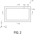
- FIG. 2 is a plan view of the planar illumination device 1 installed with the liquid crystal panel 101.
- a bottom surface of the planar illumination device 1 is in an X-Y plane and the thickness direction of the planar illumination device 1 is defined as a Z direction.
- the X-axis direction corresponds to the horizontal direction (H)
- the Y-axis direction corresponds to the vertical direction (V), as already illustrated in FIG. 1 .
- the horizontal direction and the vertical direction in the use state of the light being reflected by the windshield 104 and being visible to the user may be simply referred to as a "horizontal direction” and a "vertical direction", respectively.
- the outer planar shape of the planar illumination device 1 is substantially rectangular, and the liquid crystal panel 101 is disposed at an exit surface.
- the periphery of the liquid crystal panel 101 serves as a frame edge part 101b, and the liquid crystal panel 101 inside the frame edge part 101b serves as a display area 101a.
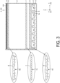
- FIG. 3 is a cross-sectional view taken along line A-A in FIG. 2 .
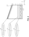
- FIG. 4 is a cross-sectional view taken along line B-B in FIG. 2 .
- the planar illumination device 1 includes a box-shaped frame 2 with a bottom. At a bottom part of the frame 2, a substrate 3 formed of aluminum or the like excellent in heat dissipation is disposed.
- a plurality of light sources 4 such as light emitting diodes (LEDs) are disposed two-dimensionally in a grid pattern at the substrate 3 after being appropriately insulated. The individual light sources 4 are individually driven and light emission is individually controlled, so that so-called local dimming is supported.
- LEDs light emitting diodes
- a reflector 5 including four reflection surfaces 5a and 5b surrounding each of the plurality of light sources 4 is disposed at an exit side of the substrate 3. At the exit side, the light sources 4 are disposed.
- the reflector 5 is made of resin or the like.
- the reflector 5 may be disposed in a state of floating from the light sources 4.
- the reflector 5 may be omitted.
- a condenser lens 6 for concentrating light is disposed at an exit side of the reflector 5 in parallel with the substrate 3.
- the condenser lens 6 is formed with a linear Fresnel lens 6a at a lower incident surface in the drawing, and the linear Fresnel lens 6a includes grooves constituting an uneven surface of the lens and extending in one direction (depth direction (Y-axis direction) in the drawing). Furthermore, as described in FIG.
- the condenser lens 6 is formed with a linear Fresnel lens 6b at an upper exit surface in the drawing, and the linear Fresnel lens 6b includes grooves constituting an uneven surface of the lens and extending in a direction (left-right direction (X-axis direction) in the drawing) orthogonal to the one direction of the lower surface.
- Each of the linear Fresnel lenses 6a and 6b has a prism structure. In the prism structure, a cylindrical convex lens is formed as the Fresnel lens.
- the grooves are periodically formed in accordance with the pitch of the light sources 4 disposed immediately below, and the angle of the prism is inverted at a segment boundary between adjacent segments. This Fresnel lens is manufactured more easily than an annular Fresnel lens.
- a field lens 7 for spreading light distribution is disposed at an exit side of the condenser lens 6.
- the field lens 7 is formed with a lenticular lens 7a at a lower surface in the drawing, and the lenticular lens 7a includes grooves constituting an uneven surface of the lens and extending in one direction (depth direction (Y-axis direction) in the drawing).
- the field lens 7 is formed with a lenticular lens 7b at an upper surface in the drawing, and the lenticular lens 7b includes grooves constituting an uneven surface of the lens and extending in a direction (left-right direction (X-axis direction) in the drawing) orthogonal to the one direction of the lower surface.
- the lenticular lenses 7a and 7b have a prism shape with a semi-cylindrical cross section and spread incident light.
- a diffuser plate spreads light in all directions and thus reduces efficiency.
- the lenticular lenses 7a and 7b are advantageous in that the spread of light distribution can be adjusted within a necessary range based on the cross-sectional shape and that light efficiency is not reduced.
- a field lens 8 for spreading light distribution outward is disposed.
- the reason to spread light distribution is to provide characteristics of light distribution open outward so that the visibility at the peripheral edge is not deteriorated even when light is converged by the concave mirror 103 included in the head-up display system 100 ( FIG. 1 ).
- the field lens 8 is not inclined with respect to the X-axis direction (horizontal direction) and is disposed in parallel with the substrate 3, the condenser lens 6, and the field lens 7.
- the field lens 8 is disposed inclined with respect to the substrate 3, the condenser lens 6 and the field lens 7 as illustrated in FIG. 4 .
- the field lens 8 is formed with a linear prism 8a at a lower surface in the drawing, and the linear prism 8a includes grooves constituting an uneven surface of the lens and extending in one direction (depth direction (Y-axis direction) in the drawing).
- the field lens 8 is formed with a linear prism 8b at an upper surface in the drawing, and the linear prism 8b includes grooves constituting an uneven surface of the lens and extending in a direction (left-right direction (X-axis direction) in the drawing) orthogonal to the one direction of the lower surface.
- the linear prisms 8a and 8b cause light passing through a center part of the entire width to travel straight in the Z-axis direction, and the optical axis is directed outward at each location closer to the outside. Note that the light passing through the center part of the entire width may also be inclined with respect to the Z-axis direction.
- an optical sheet 9 matching the characteristics of the liquid crystal panel 101 to be mounted is disposed in parallel with the field lens 8.
- a polarization reflective sheet or a diffusion sheet is used as the optical sheet 9 .
- the optical sheet 9 has a thickness of, for example, about 0.4 mm.
- the liquid crystal panel 101 for forming an image to be projected is disposed in parallel with the optical sheet 9 and the field lens 8. What is important here is that a uniform optical distance is kept between the field lens 8 and the liquid crystal panel 101. It is also important that both the field lens 8 and the liquid crystal panel 101 are close to each other. The amount of light spreading toward an adjacent dimming zone can be made smaller as the distance between the field lens 8 and the liquid crystal panel 101 decreases, so that the loss of light is reduced and the contrast is improved.
- the distance between the field lens 8 and the liquid crystal panel 101 may be zero (close to each other in a state of having substantially no clearance), but is preferably equal to or less than 3 mm, more preferably equal to or less than 2 mm, in consideration of the optical characteristics, the thickness of the optical sheet 9 when the optical sheet 9 is provided, the thickness of a positioning mechanism of each optical member, and the like. Note that as long as the field lens 8 and the liquid crystal panel 101 are as close as 3 mm or less from each other, the field lens 8 and the liquid crystal panel 101 are not necessarily disposed in parallel.
- FIG. 5 is a diagram illustrating an example of light distribution in the horizontal direction (X-axis direction).
- light L11 exiting from the light sources 4 is converged into substantially parallel light by the condenser lens 6 (the linear Fresnel lens 6a at the lower surface) to become light L12.
- the light distribution of the light L12 is spread by the field lens 7 (the lenticular lens 7a at the lower surface) without change in the optical axis, and light L13 is formed.
- the optical axis of the light L13 at each location is inclined outward by the field lens 8 (the linear prism 8a at the lower surface), the light distribution is spread outward, and light L14 passing through the optical sheet 9 and the liquid crystal panel 101 is formed.
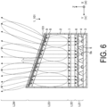
- FIG. 6 is a diagram illustrating an example of light distribution in the vertical direction (Y-axis direction).
- light L21 exiting from the light sources 4 is converged into substantially parallel light by the condenser lens 6 (the linear Fresnel lens 6b at the upper surface) to become light L22.
- the light distribution of the light L22 is spread by the field lens 7 (the lenticular lens 7b at the upper surface) without change in the optical axis, and light L23 is formed.
- the optical axis of the light L23 at each location is inclined outward by the field lens 8 (the linear prism 8b at the upper surface), the light distribution is spread outward, and light L24 passing through the optical sheet 9 and the liquid crystal panel 101 is formed.
- FIG. 7 is a diagram illustrating a configuration example of a planar illumination device 1' and a liquid crystal panel 101' according to Comparative Example #1 and an example of light distribution in the vertical direction (Y-axis direction).
- the planar illumination device 1' according to Comparative Example #1 does not support local dimming. That is, a substrate 3', light sources 4', a reflector 5', a condenser lens 6', a field lens 8', an optical sheet 9' and the liquid crystal panel 101' are disposed at a frame 2' in this order from a bottom part, and the whole is covered by a small number of light sources 4'.
- FIG. 8 is a diagram illustrating a configuration example of a planar illumination device 1" and a liquid crystal panel 101" according to Comparative Example #2 and an example of light distribution in the vertical direction (Y-axis direction).
- the planar illumination device 1" according to Comparative Example #2 supports local dimming.
- a substrate 3", light sources 4", a reflector 5", a condenser lens 6", a field lens 7", a field lens 8", an optical sheet 9", and a liquid crystal panel 101" are disposed at a frame 2" in this order from a bottom part.
- the field lens 8" is disposed in parallel with the substrate 3", the condenser lens 6", and the field lens 7".
- the zone area corresponds to each light source 4" and is surrounded by vertically extending two-dot-dash lines.
- light beams L1" and L2", and the like in FIG. 8 are light beams going out of zone areas of local dimming.
- Such light deteriorates the contrast and luminance uniformity. That is, unnecessary light is given due to light going into an adjacent zone area when the adjacent zone area is off (the light amount is zero). Furthermore, the light amount in the original zone area of the light going into the adjacent zone area becomes also insufficient, so that the contrast and luminance uniformity are reduced as a whole.
- the present embodiment can also be applied to a normal backlight not supporting local dimming and exerts a certain effect. That is, in the case of the planar illumination device 1' not supporting local dimming in FIG. 7 , a light beam is incident on the frame 2' at an end part (left end in FIG. 7 ) having a largest optical distance, so that the loss of light occurs. However, when the configuration of the present embodiment is applied, the loss of light at the end part can be prevented.
- a planar illumination device includes a plurality of light sources disposed two-dimensionally on a substrate, light emission of the plurality of light sources being individually controlled, a condenser lens disposed at an exit side of the light sources in parallel with the substrate and configured to converge light exiting from the light sources into substantially parallel light, and a field lens disposed at an exit side of the condenser lens, disposed inclined in at least one direction orthogonal to a plane parallel to the substrate, and configured to spread light incident from the condenser lens outward to have a uniform optical distance between the field lens and a liquid crystal panel attached externally.
- the contrast and luminance uniformity can be improved.
- the present embodiment can also be applied to a normal backlight not supporting local dimming and exerts a certain effect.
- the field lens is provided in vicinity to the liquid crystal panel.
- the amount of light spread by the field lens toward an adjacent dimming zone can be reduced, so that the loss of light is reduced, and the contrast is improved.
- the condenser lens is formed with linear Fresnel lenses including grooves forming unevenness at an incident side and at an exit side, directions of the grooves being orthogonal to each other.
- the field lens is formed with linear prisms at an incident side and at an exit side, the linear prisms including grooves, the grooves forming unevenness and extending in orthogonal directions.
- the condenser lens can be easily achieved.
- the planar illumination device also includes another field lens provided between the condenser lens and the field lens and in parallel with the substrate.
- the other field lens is formed with lenticular lenses including grooves forming unevenness at an incident side and at an exit side, directions of the grooves being orthogonal to each other.
- the planar illumination device includes a reflector disposed at an exit side of the substrate, the reflector including reflection surfaces surrounding the light sources.
- the planar illumination device also includes an optical sheet composed of a polarization reflective sheet or a diffusion sheet, the optical sheet being disposed at an exit side of the field lens disposed in an inclined manner.
- an optical sheet composed of a polarization reflective sheet or a diffusion sheet, the optical sheet being disposed at an exit side of the field lens disposed in an inclined manner.
- a planar illumination device illuminates a liquid crystal panel disposed inclined with respect to an optical axis.
- the planar illumination device includes a plurality of light sources disposed two-dimensionally on a substrate, and light emission of the plurality of light sources being individually controlled, a condenser lens at an exit side of the light sources, the condenser lens being configured to converge light exiting from the light sources into substantially parallel light, and a field lens disposed at an exit side of the condenser lens and configured to spread light incident from the condenser lens outward, wherein the field lens is disposed in parallel with and in vicinity to the liquid crystal panel attached externally.
- the contrast and luminance uniformity can be improved.
- a planar illumination device illuminates a liquid crystal panel disposed inclined with respect to an optical axis.
- the planar illumination device includes a plurality of light sources disposed two-dimensionally on a substrate, and light emission of the plurality of light sources being individually controlled, a condenser lens at an exit side of the light sources, the condenser lens being configured to converge light exiting from the light sources into substantially parallel light, and a field lens disposed at an exit side of the condenser lens and configured to spread light incident from the condenser lens outward, wherein the field lens is disposed in vicinity to the liquid crystal panel attached externally.
- the contrast and luminance uniformity can be improved.
- the field lens is as close as 3 mm or less from the liquid crystal panel. Thus, a predetermined effect can be expected.
- the present invention is not limited to the embodiment described above.
- a configuration obtained by appropriately combining the above-mentioned components is also included in the present invention.
- Further effects and modification examples can be easily derived by a person skilled in the art.
- a wide range of aspects of the present invention is not limited to the embodiment described above and may be modified variously.
- 1 Planar illumination device 2 Frame, 3 Substrate, 4 Light source, 5 Reflector, 5a, 5b Reflection surface, 6 Condenser lens, 6a, 6b Linear Fresnel lens, 7 Field lens, 7a, 7b Lenticular lens, 8 Field lens, 8a, 8b Linear prism, 9 Optical sheet, 100 Head-up display system, 101 Liquid crystal panel, 101a Display area, 101b Frame edge part, 102 Mirror, 103 Concave mirror, 104 Windshield, EB Eye box
Landscapes
- Physics & Mathematics (AREA)
- Nonlinear Science (AREA)
- General Physics & Mathematics (AREA)
- Optics & Photonics (AREA)
- Mathematical Physics (AREA)
- Chemical & Material Sciences (AREA)
- Crystallography & Structural Chemistry (AREA)
- Engineering & Computer Science (AREA)
- General Engineering & Computer Science (AREA)
- Planar Illumination Modules (AREA)
- Liquid Crystal (AREA)
Abstract
Description
- The present invention relates to a planar illumination device.
- A head-up display (HUD) using a windshield or the like of an automobile is known (see, for example,
Patent Documents 1 and 2). Since a light source unit of such a head-up display is installed near a windshield exposed to sunlight, countermeasures against heat and stray light due to sunlight are taken in most cases. - For example, in a planar illumination device used as a backlight of a head-up display, a liquid crystal panel is disposed at an exit surface side of the planar illumination device, and one or more mirrors are provided at subsequent stages of the liquid crystal panel, and projection is performed on a windshield. Thus, the liquid crystal panel and the planar illumination device may be deteriorated by heat of sunlight entering from the outside of the automobile through the windshield and the mirror, or stray light may adversely affect display.
- As a countermeasure against this problem, the liquid crystal panel is disposed in most cases so as to be inclined in the same direction as a first-stage mirror with respect to a main optical axis from the planar illumination device to the first-stage mirror. Since the liquid crystal panel is disposed in an inclined state, sunlight entering in a direction opposite to a direction at the time of projection is easily reflected at the surface of the liquid crystal panel, and entry of the sunlight into the liquid crystal panel and the planar illumination device is prevented. Thus, a problem caused by heat and stray light is reduced.
-
- Patent Document 1:
JP 2018-83593 A - Patent Document 2:
JP 2019-61128 A - The inclination of the above-described liquid crystal panel causes no particular problem in a planar illumination device not supporting local dimming, but causes a new problem of reducing a contrast and luminance uniformity in a planar illumination device supporting local dimming. Local dimming is a technique of significantly increasing a contrast ratio between different areas in the same screen by controlling the light amount of each light source in a direct-type planar illumination device including two-dimensionally disposed light sources such as light emitting diodes (LEDs).
- That is, in most cases, this type of planar illumination device is provided with characteristics of light distribution open outward so that the visibility at a peripheral edge is not deteriorated even when light is converged by a concave mirror used as a part of subsequent stages. Thus, when the liquid crystal panel is disposed inclined with respect to a main optical axis of the planar illumination device, a difference in optical distance is made between a field lens for providing characteristics of light distribution open outward and the liquid crystal panel. Due to this difference in optical distance, light going out of a zone area of local dimming (dimming zone) is generated, and a contrast and luminance uniformity are reduced.
- The present invention has been made in light of the foregoing, and an object is to provide a planar illumination device capable of improving a contrast and luminance uniformity.
- To solve the above-described problem and achieve the object, a planar illumination device according to one aspect of the present invention includes a plurality of light sources, a condenser lens, and a field lens. The plurality of light sources are disposed two-dimensionally on a substrate, and light emission of the plurality of light sources is individually controlled. The condenser lens is disposed at an exit side of the light sources in parallel with the substrate and configured to converge light exiting from the light sources into substantially parallel light. The field lens is disposed at an exit side of the condenser lens, disposed inclined in at least one direction orthogonal to a plane parallel to the substrate, and configured to spread light incident from the condenser lens outward to have a uniform optical distance between the field lens and a liquid crystal panel attached externally.
- A planar illumination device according to an aspect of the present invention can improve a contrast and luminance uniformity.
-
-
FIG. 1 is a diagram illustrating a configuration example of a head-up display system. -
FIG. 2 is a plan view of a planar illumination device installed with a liquid crystal panel. -
FIG. 3 is a cross-sectional view taken along line A-A inFIG. 2 . -
FIG. 4 is a cross-sectional view taken along line B-B inFIG. 2 . -
FIG. 5 is a diagram illustrating an example of light distribution in a horizontal direction (X-axis direction). -
FIG. 6 is a diagram illustrating an example of light distribution in a vertical direction (Y-axis direction). -
FIG. 7 is a diagram illustrating a configuration example of a planar illumination device and a liquid crystal panel according toComparative Example # 1 and an example of light distribution in a vertical direction (Y-axis direction). -
FIG. 8 is a diagram illustrating a configuration example of a planar illumination device and a liquid crystal panel according toComparative Example # 2 and an example of light distribution in a vertical direction (Y-axis direction). - A planar illumination device according to an embodiment will be described below with reference to the drawings. Note that the present invention is not limited to the embodiment. Furthermore, the dimensional relationships between elements, proportions of the elements, and the like in the drawings may differ from reality. In some cases, the dimensional relationship and the ratios in the drawings may differ from each other. Furthermore, the contents described in one embodiment or modification example are applied in principle to other embodiments or modification examples.
-
FIG. 1 is a diagram illustrating a configuration example of a head-updisplay system 100. InFIG. 1 , in the case of the head-updisplay system 100 installed at an automobile, the traveling direction of the automobile is the left direction (positive direction of a Y-axis) in the drawing. - In
FIG. 1 , light exiting from aplanar illumination device 1 passes through a liquid crystal panel 101 (L1), is reflected by a mirror 102 (L2), and is guided to aconcave mirror 103. Awindshield 104 of the automobile is irradiated with light (L3) reflected from theconcave mirror 103, light (L4) reflected by thewindshield 104 enters an eye box (field of vision) EB of a driver or the like, and an image displayed at theliquid crystal panel 101 is recognized as a virtual image. Note that "H (horizontal direction)" written along with an X-axis direction and "V (vertical direction)" written along with a Y-axis direction are a horizontal direction and a vertical direction of the virtual image viewed from the eye box EB. - In addition, the
liquid crystal panel 101 is disposed so as to be inclined in the same direction as themirror 102 with respect to a main optical axis (L1) from theplanar illumination device 1 toward themirror 102 at a first state. Theliquid crystal panel 101 is disposed in an inclined state, and thus when sunlight emitted from above thewindshield 104 enters theliquid crystal panel 101 via thewindshield 104, theconcave mirror 103, and themirror 102, the sunlight is easily reflected at the surface of theliquid crystal panel 101. As a result, the sunlight is prevented from entering theliquid crystal panel 101 and theplanar illumination device 1, and thus a problem caused by heat and stray light is reduced. - Note that the components and arrangement of the head-up
display system 100 inFIG. 1 are mere examples, and the optical axis of theplanar illumination device 1 may be set in the horizontal direction, or the configuration of the mirrors, including the number of the mirrors, may be different. -
FIG. 2 is a plan view of theplanar illumination device 1 installed with theliquid crystal panel 101. For convenience, a bottom surface of theplanar illumination device 1 is in an X-Y plane and the thickness direction of theplanar illumination device 1 is defined as a Z direction. In a use state of light being reflected by thewindshield 104 and being visible to a user, the X-axis direction corresponds to the horizontal direction (H) and the Y-axis direction corresponds to the vertical direction (V), as already illustrated inFIG. 1 . Note that, in the following, the horizontal direction and the vertical direction in the use state of the light being reflected by thewindshield 104 and being visible to the user may be simply referred to as a "horizontal direction" and a "vertical direction", respectively. - In
FIG. 2 , the outer planar shape of theplanar illumination device 1 is substantially rectangular, and theliquid crystal panel 101 is disposed at an exit surface. The periphery of theliquid crystal panel 101 serves as aframe edge part 101b, and theliquid crystal panel 101 inside theframe edge part 101b serves as adisplay area 101a. -
FIG. 3 is a cross-sectional view taken along line A-A inFIG. 2 .FIG. 4 is a cross-sectional view taken along line B-B inFIG. 2 . InFIGs. 3 and4 , theplanar illumination device 1 includes a box-shaped frame 2 with a bottom. At a bottom part of theframe 2, asubstrate 3 formed of aluminum or the like excellent in heat dissipation is disposed. A plurality oflight sources 4 such as light emitting diodes (LEDs) are disposed two-dimensionally in a grid pattern at thesubstrate 3 after being appropriately insulated. Theindividual light sources 4 are individually driven and light emission is individually controlled, so that so-called local dimming is supported. - A
reflector 5 including fourreflection surfaces light sources 4 is disposed at an exit side of thesubstrate 3. At the exit side, thelight sources 4 are disposed. Thereflector 5 is made of resin or the like. Thereflector 5 may be disposed in a state of floating from thelight sources 4. Thereflector 5 may be omitted. - A
condenser lens 6 for concentrating light is disposed at an exit side of thereflector 5 in parallel with thesubstrate 3. As described inFIG. 3 , thecondenser lens 6 is formed with alinear Fresnel lens 6a at a lower incident surface in the drawing, and thelinear Fresnel lens 6a includes grooves constituting an uneven surface of the lens and extending in one direction (depth direction (Y-axis direction) in the drawing). Furthermore, as described inFIG. 4 , thecondenser lens 6 is formed with alinear Fresnel lens 6b at an upper exit surface in the drawing, and thelinear Fresnel lens 6b includes grooves constituting an uneven surface of the lens and extending in a direction (left-right direction (X-axis direction) in the drawing) orthogonal to the one direction of the lower surface. Each of thelinear Fresnel lenses light sources 4 disposed immediately below, and the angle of the prism is inverted at a segment boundary between adjacent segments. This Fresnel lens is manufactured more easily than an annular Fresnel lens. - A
field lens 7 for spreading light distribution is disposed at an exit side of thecondenser lens 6. As described inFIG. 3 , thefield lens 7 is formed with a lenticular lens 7a at a lower surface in the drawing, and the lenticular lens 7a includes grooves constituting an uneven surface of the lens and extending in one direction (depth direction (Y-axis direction) in the drawing). As described inFIG. 4 , thefield lens 7 is formed with alenticular lens 7b at an upper surface in the drawing, and thelenticular lens 7b includes grooves constituting an uneven surface of the lens and extending in a direction (left-right direction (X-axis direction) in the drawing) orthogonal to the one direction of the lower surface. Thelenticular lenses 7a and 7b have a prism shape with a semi-cylindrical cross section and spread incident light. A diffuser plate spreads light in all directions and thus reduces efficiency. However, thelenticular lenses 7a and 7b are advantageous in that the spread of light distribution can be adjusted within a necessary range based on the cross-sectional shape and that light efficiency is not reduced. - At an exit side of the
field lens 7, afield lens 8 for spreading light distribution outward is disposed. The reason to spread light distribution is to provide characteristics of light distribution open outward so that the visibility at the peripheral edge is not deteriorated even when light is converged by theconcave mirror 103 included in the head-up display system 100 (FIG. 1 ). As illustrated inFIG. 3 , thefield lens 8 is not inclined with respect to the X-axis direction (horizontal direction) and is disposed in parallel with thesubstrate 3, thecondenser lens 6, and thefield lens 7. Moreover, regarding the Y-axis direction (vertical direction), thefield lens 8 is disposed inclined with respect to thesubstrate 3, thecondenser lens 6 and thefield lens 7 as illustrated inFIG. 4 . - As illustrated in
FIG. 3 , thefield lens 8 is formed with alinear prism 8a at a lower surface in the drawing, and thelinear prism 8a includes grooves constituting an uneven surface of the lens and extending in one direction (depth direction (Y-axis direction) in the drawing). As illustrated inFIG. 4 , thefield lens 8 is formed with alinear prism 8b at an upper surface in the drawing, and thelinear prism 8b includes grooves constituting an uneven surface of the lens and extending in a direction (left-right direction (X-axis direction) in the drawing) orthogonal to the one direction of the lower surface. Thelinear prisms - At an exit side of the
field lens 8, anoptical sheet 9 matching the characteristics of theliquid crystal panel 101 to be mounted is disposed in parallel with thefield lens 8. As theoptical sheet 9, a polarization reflective sheet or a diffusion sheet is used. Theoptical sheet 9 has a thickness of, for example, about 0.4 mm. - At an exit side of the
optical sheet 9, theliquid crystal panel 101 for forming an image to be projected is disposed in parallel with theoptical sheet 9 and thefield lens 8. What is important here is that a uniform optical distance is kept between thefield lens 8 and theliquid crystal panel 101. It is also important that both thefield lens 8 and theliquid crystal panel 101 are close to each other. The amount of light spreading toward an adjacent dimming zone can be made smaller as the distance between thefield lens 8 and theliquid crystal panel 101 decreases, so that the loss of light is reduced and the contrast is improved. The distance between thefield lens 8 and theliquid crystal panel 101 may be zero (close to each other in a state of having substantially no clearance), but is preferably equal to or less than 3 mm, more preferably equal to or less than 2 mm, in consideration of the optical characteristics, the thickness of theoptical sheet 9 when theoptical sheet 9 is provided, the thickness of a positioning mechanism of each optical member, and the like. Note that as long as thefield lens 8 and theliquid crystal panel 101 are as close as 3 mm or less from each other, thefield lens 8 and theliquid crystal panel 101 are not necessarily disposed in parallel. -
FIG. 5 is a diagram illustrating an example of light distribution in the horizontal direction (X-axis direction). InFIG. 5 , light L11 exiting from thelight sources 4 is converged into substantially parallel light by the condenser lens 6 (thelinear Fresnel lens 6a at the lower surface) to become light L12. The light distribution of the light L12 is spread by the field lens 7 (the lenticular lens 7a at the lower surface) without change in the optical axis, and light L13 is formed. The optical axis of the light L13 at each location is inclined outward by the field lens 8 (thelinear prism 8a at the lower surface), the light distribution is spread outward, and light L14 passing through theoptical sheet 9 and theliquid crystal panel 101 is formed. -
FIG. 6 is a diagram illustrating an example of light distribution in the vertical direction (Y-axis direction). InFIG. 6 , light L21 exiting from thelight sources 4 is converged into substantially parallel light by the condenser lens 6 (thelinear Fresnel lens 6b at the upper surface) to become light L22. The light distribution of the light L22 is spread by the field lens 7 (thelenticular lens 7b at the upper surface) without change in the optical axis, and light L23 is formed. The optical axis of the light L23 at each location is inclined outward by the field lens 8 (thelinear prism 8b at the upper surface), the light distribution is spread outward, and light L24 passing through theoptical sheet 9 and theliquid crystal panel 101 is formed. -
FIG. 7 is a diagram illustrating a configuration example of a planar illumination device 1' and a liquid crystal panel 101' according toComparative Example # 1 and an example of light distribution in the vertical direction (Y-axis direction). InFIG. 7 , the planar illumination device 1' according toComparative Example # 1 does not support local dimming. That is, a substrate 3', light sources 4', a reflector 5', a condenser lens 6', a field lens 8', an optical sheet 9' and the liquid crystal panel 101' are disposed at a frame 2' in this order from a bottom part, and the whole is covered by a small number of light sources 4'. Thus, there is no concept of a zone area in local dimming, and even when the optical distance between the field lens 8' and the liquid crystal panel 101' is not uniform, there is no problem about a dimming zone. However, at an end part (left end inFIG. 7 ) having a largest optical distance, a light beam is incident on the frame 2', so that the loss of light occurs. -
FIG. 8 is a diagram illustrating a configuration example of aplanar illumination device 1" and aliquid crystal panel 101" according toComparative Example # 2 and an example of light distribution in the vertical direction (Y-axis direction). InFIG. 8 , theplanar illumination device 1" according toComparative Example # 2 supports local dimming. Asubstrate 3",light sources 4", areflector 5", acondenser lens 6", afield lens 7", afield lens 8", anoptical sheet 9", and aliquid crystal panel 101" are disposed at aframe 2" in this order from a bottom part. However, thefield lens 8" is disposed in parallel with thesubstrate 3", thecondenser lens 6", and thefield lens 7". - Thus, light going out of a zone area of local dimming is generated. The zone area corresponds to each
light source 4" and is surrounded by vertically extending two-dot-dash lines. For example, light beams L1" and L2", and the like inFIG. 8 are light beams going out of zone areas of local dimming. Such light deteriorates the contrast and luminance uniformity. That is, unnecessary light is given due to light going into an adjacent zone area when the adjacent zone area is off (the light amount is zero). Furthermore, the light amount in the original zone area of the light going into the adjacent zone area becomes also insufficient, so that the contrast and luminance uniformity are reduced as a whole. - In this regard, since a uniform optical distance is kept between the
field lens 8 and theliquid crystal panel 101 in the above-described embodiment as illustrated inFIG. 6 , the generation of light going out of zone areas of local dimming is suppressed, and the contrast and luminance uniformity can be prevented from being reduced and can be improved. In addition, since thefield lens 8 and theliquid crystal panel 101 are close to each other, these effects are more efficiently exerted. Note that the present embodiment can also be applied to a normal backlight not supporting local dimming and exerts a certain effect. That is, in the case of the planar illumination device 1' not supporting local dimming inFIG. 7 , a light beam is incident on the frame 2' at an end part (left end inFIG. 7 ) having a largest optical distance, so that the loss of light occurs. However, when the configuration of the present embodiment is applied, the loss of light at the end part can be prevented. - The embodiment of the present invention has been described above; however, the present invention is not limited to the above-mentioned embodiment and may be modified in various ways without departing from the gist of the invention.
- As described above, a planar illumination device according to an embodiment includes a plurality of light sources disposed two-dimensionally on a substrate, light emission of the plurality of light sources being individually controlled, a condenser lens disposed at an exit side of the light sources in parallel with the substrate and configured to converge light exiting from the light sources into substantially parallel light, and a field lens disposed at an exit side of the condenser lens, disposed inclined in at least one direction orthogonal to a plane parallel to the substrate, and configured to spread light incident from the condenser lens outward to have a uniform optical distance between the field lens and a liquid crystal panel attached externally. Thus, the contrast and luminance uniformity can be improved. That is, even when the field lens spreads the light incident from the condenser lens outward, it is possible to suppress the generation of light going out of zone areas of local dimming and to prevent the contrast and luminance uniformity from being reduced since the uniform optical distance is kept between the field lens and the liquid crystal panel. Note that the present embodiment can also be applied to a normal backlight not supporting local dimming and exerts a certain effect.
- Further, the field lens is provided in vicinity to the liquid crystal panel. Thus, the amount of light spread by the field lens toward an adjacent dimming zone can be reduced, so that the loss of light is reduced, and the contrast is improved.
- Further, the condenser lens is formed with linear Fresnel lenses including grooves forming unevenness at an incident side and at an exit side, directions of the grooves being orthogonal to each other. The field lens is formed with linear prisms at an incident side and at an exit side, the linear prisms including grooves, the grooves forming unevenness and extending in orthogonal directions. Thus, the condenser lens can be easily achieved.
- The planar illumination device also includes another field lens provided between the condenser lens and the field lens and in parallel with the substrate. The other field lens is formed with lenticular lenses including grooves forming unevenness at an incident side and at an exit side, directions of the grooves being orthogonal to each other. As a result, the luminance uniformity can be improved without reduction in light efficiency as in the case of a diffusion plate.
- Furthermore, the planar illumination device includes a reflector disposed at an exit side of the substrate, the reflector including reflection surfaces surrounding the light sources. As a result, light leaking from the light sources toward the substrate is not wasted, and the light efficiency is improved.
- The planar illumination device also includes an optical sheet composed of a polarization reflective sheet or a diffusion sheet, the optical sheet being disposed at an exit side of the field lens disposed in an inclined manner. Thus, it is easy to achieve optical characteristics corresponding to the liquid crystal panel attached externally.
- Moreover, a planar illumination device illuminates a liquid crystal panel disposed inclined with respect to an optical axis. The planar illumination device includes a plurality of light sources disposed two-dimensionally on a substrate, and light emission of the plurality of light sources being individually controlled, a condenser lens at an exit side of the light sources, the condenser lens being configured to converge light exiting from the light sources into substantially parallel light, and a field lens disposed at an exit side of the condenser lens and configured to spread light incident from the condenser lens outward, wherein the field lens is disposed in parallel with and in vicinity to the liquid crystal panel attached externally. Thus, the contrast and luminance uniformity can be improved.
- Furthermore, a planar illumination device illuminates a liquid crystal panel disposed inclined with respect to an optical axis. The planar illumination device includes a plurality of light sources disposed two-dimensionally on a substrate, and light emission of the plurality of light sources being individually controlled, a condenser lens at an exit side of the light sources, the condenser lens being configured to converge light exiting from the light sources into substantially parallel light, and a field lens disposed at an exit side of the condenser lens and configured to spread light incident from the condenser lens outward, wherein the field lens is disposed in vicinity to the liquid crystal panel attached externally. Thus, the contrast and luminance uniformity can be improved.
- In addition, the field lens is as close as 3 mm or less from the liquid crystal panel. Thus, a predetermined effect can be expected.
- The present invention is not limited to the embodiment described above. A configuration obtained by appropriately combining the above-mentioned components is also included in the present invention. Further effects and modification examples can be easily derived by a person skilled in the art. Thus, a wide range of aspects of the present invention is not limited to the embodiment described above and may be modified variously.
- 1 Planar illumination device, 2 Frame, 3 Substrate, 4 Light source, 5 Reflector, 5a, 5b Reflection surface, 6 Condenser lens, 6a, 6b Linear Fresnel lens, 7 Field lens, 7a, 7b Lenticular lens, 8 Field lens, 8a, 8b Linear prism, 9 Optical sheet, 100 Head-up display system, 101 Liquid crystal panel, 101a Display area, 101b Frame edge part, 102 Mirror, 103 Concave mirror, 104 Windshield, EB Eye box
Claims (9)
- A planar illumination device, comprising:a plurality of light sources disposed two-dimensionally on a substrate, light emission of the plurality of light sources being individually controlled;a condenser lens disposed at an exit side of the light sources in parallel with the substrate and configured to converge light exiting from the light sources into substantially parallel light; anda field lens disposed at an exit side of the condenser lens, disposed inclined in at least one direction orthogonal to a plane parallel to the substrate, and configured to spread light incident from the condenser lens outward to have a uniform optical distance between the field lens and a liquid crystal panel attached externally.
- The planar illumination device according to claim 1, wherein
the field lens is provided in vicinity to the liquid crystal panel. - The planar illumination device according to claim 1 or 2, whereinthe condenser lens is formed with linear Fresnel lenses including grooves forming unevenness at an incident side and at an exit side, directions of the grooves being orthogonal to each other, andthe field lens is formed with linear prisms including grooves forming unevenness at an incident side and at an exit side, directions of the grooves being orthogonal to each other.
- The planar illumination device according to any one of claims 1 to 3, comprisinganother field lens provided between the condenser lens and the field lens and in parallel with the substrate,the other field lens is formed with lenticular lenses including grooves forming unevenness at an incident side and at an exit side, directions of the grooves being orthogonal to each other.
- The planar illumination device according to any one of claims 1 to 4, comprising
a reflector disposed at an exit side of the substrate and including reflection surfaces surrounding the light sources. - The planar illumination device according to any one of claims 1 to 5, comprising
an optical sheet composed of a polarization reflective sheet or a diffusion sheet, the optical sheet being disposed at an exit side of the field lens disposed inclined. - A planar illumination device illuminating a liquid crystal panel disposed inclined with respect to an optical axis, the planar illumination device comprising:a plurality of light sources disposed two-dimensionally on a substrate, light emission of the plurality of light sources being individually controlled;a condenser lens at an exit side of the light sources, the condenser lens being configured to converge light exiting from the light sources into substantially parallel light; anda field lens disposed at an exit side of the condenser lens and configured to spread light incident from the condenser lens outward, whereinthe field lens is disposed in parallel with and in vicinity to the liquid crystal panel attached externally.
- A planar illumination device illuminating a liquid crystal panel disposed inclined with respect to an optical axis, the planar illumination device comprising:a plurality of light sources disposed two-dimensionally on a substrate, light emission of the plurality of light sources being individually controlled;a condenser lens at an exit side of the light sources, the condenser lens being configured to converge light exiting from the light sources into substantially parallel light; anda field lens disposed at an exit side of the condenser lens and configured to spread light incident from the condenser lens outward, whereinthe field lens is disposed in vicinity to the liquid crystal panel attached externally.
- The planar illumination device according to claim 7 or 8, wherein
the field lens is in vicinity to the liquid crystal panel by 3 mm or less.
Applications Claiming Priority (2)
| Application Number | Priority Date | Filing Date | Title |
|---|---|---|---|
| JP2022022222A JP7406582B2 (en) | 2022-02-16 | 2022-02-16 | Spread lighting device |
| PCT/JP2022/048623 WO2023157501A1 (en) | 2022-02-16 | 2022-12-28 | Planar illumination device |
Publications (2)
| Publication Number | Publication Date |
|---|---|
| EP4481265A1 true EP4481265A1 (en) | 2024-12-25 |
| EP4481265A4 EP4481265A4 (en) | 2026-01-21 |
Family
ID=87578065
Family Applications (1)
| Application Number | Title | Priority Date | Filing Date |
|---|---|---|---|
| EP22927382.6A Pending EP4481265A4 (en) | 2022-02-16 | 2022-12-28 | SURFACE LIGHTING SYSTEM |
Country Status (6)
| Country | Link |
|---|---|
| US (1) | US12504659B2 (en) |
| EP (1) | EP4481265A4 (en) |
| JP (2) | JP7406582B2 (en) |
| KR (1) | KR102890256B1 (en) |
| CN (1) | CN118696198A (en) |
| WO (1) | WO2023157501A1 (en) |
Families Citing this family (1)
| Publication number | Priority date | Publication date | Assignee | Title |
|---|---|---|---|---|
| JP7406582B2 (en) * | 2022-02-16 | 2023-12-27 | ミネベアミツミ株式会社 | Spread lighting device |
Family Cites Families (11)
| Publication number | Priority date | Publication date | Assignee | Title |
|---|---|---|---|---|
| JP6319355B2 (en) * | 2016-02-23 | 2018-05-09 | 株式会社デンソー | Head-up display device |
| JP6508125B2 (en) | 2016-05-18 | 2019-05-08 | 株式会社デンソー | HEAD-UP DISPLAY DEVICE AND IMAGE PROJECTION UNIT |
| JP2018083593A (en) | 2016-11-25 | 2018-05-31 | 日本精機株式会社 | Display device |
| JP6711337B2 (en) * | 2017-09-07 | 2020-06-17 | 株式会社デンソー | Head-up display device and image projection unit |
| JP2019061128A (en) | 2017-09-27 | 2019-04-18 | 株式会社ジャパンディスプレイ | Display device and head-up display device |
| EP3575846A1 (en) | 2018-05-30 | 2019-12-04 | Visteon Global Technologies Inc. | Picture generation unit for head-up display |
| JP6984619B2 (en) * | 2019-01-28 | 2021-12-22 | 株式会社デンソー | Virtual image display device |
| WO2022004036A1 (en) * | 2020-07-01 | 2022-01-06 | ミネベアミツミ株式会社 | Planar illumination device |
| US11620937B2 (en) * | 2020-07-14 | 2023-04-04 | Samsung Electronics Co.. Ltd. | Light source device and light emission control method |
| CN112180668A (en) * | 2020-11-04 | 2021-01-05 | 南华智能精密机器(深圳)有限公司 | Efficient illumination system and projection method for LCD projector |
| JP7406582B2 (en) | 2022-02-16 | 2023-12-27 | ミネベアミツミ株式会社 | Spread lighting device |
-
2022
- 2022-02-16 JP JP2022022222A patent/JP7406582B2/en active Active
- 2022-12-28 CN CN202280091807.3A patent/CN118696198A/en active Pending
- 2022-12-28 US US18/836,913 patent/US12504659B2/en active Active
- 2022-12-28 KR KR1020247030854A patent/KR102890256B1/en active Active
- 2022-12-28 EP EP22927382.6A patent/EP4481265A4/en active Pending
- 2022-12-28 WO PCT/JP2022/048623 patent/WO2023157501A1/en not_active Ceased
-
2023
- 2023-12-15 JP JP2023212556A patent/JP7781130B2/en active Active
Also Published As
| Publication number | Publication date |
|---|---|
| JP2024022680A (en) | 2024-02-16 |
| JP7781130B2 (en) | 2025-12-05 |
| US20250035980A1 (en) | 2025-01-30 |
| JP7406582B2 (en) | 2023-12-27 |
| WO2023157501A1 (en) | 2023-08-24 |
| CN118696198A (en) | 2024-09-24 |
| JP2023119358A (en) | 2023-08-28 |
| KR102890256B1 (en) | 2025-11-25 |
| EP4481265A4 (en) | 2026-01-21 |
| KR20240152353A (en) | 2024-10-21 |
| US12504659B2 (en) | 2025-12-23 |
Similar Documents
| Publication | Publication Date | Title |
|---|---|---|
| US11294173B2 (en) | Display device and head-up display device | |
| KR101274891B1 (en) | Head-up display device for projecting image on screen | |
| CN103460114B (en) | HUD | |
| KR100818278B1 (en) | Lighting device for liquid crystal display | |
| JP6663890B2 (en) | Backlight unit and head-up display device | |
| CN106716228A (en) | Head-up display device | |
| JP7016456B1 (en) | Planar lighting device | |
| US12504659B2 (en) | Planar illumination device with local dimming | |
| JP6984619B2 (en) | Virtual image display device | |
| JP2020160293A (en) | Head-up display device | |
| EP4481270A1 (en) | Optical member, light source device, and head-up display | |
| EP4571173A1 (en) | Planar illuminating device | |
| TWI722799B (en) | Surface light source apparatus and liquid crystal display device | |
| CN220473724U (en) | Diffusion member, display device, head-up display device, and vehicle | |
| US20250362543A1 (en) | Display device and head-up display device | |
| KR20170042144A (en) | Head-Up display | |
| JP7817855B2 (en) | Light source device and head-up display | |
| CN115202048B (en) | Vehicle display device | |
| JP7495702B2 (en) | Lighting equipment | |
| WO2022244350A1 (en) | Planar illumination device | |
| JP2025086955A (en) | Display device and head-up display device | |
| JP2022160993A (en) | vehicle display |
Legal Events
| Date | Code | Title | Description |
|---|---|---|---|
| STAA | Information on the status of an ep patent application or granted ep patent |
Free format text: STATUS: THE INTERNATIONAL PUBLICATION HAS BEEN MADE |
|
| PUAI | Public reference made under article 153(3) epc to a published international application that has entered the european phase |
Free format text: ORIGINAL CODE: 0009012 |
|
| STAA | Information on the status of an ep patent application or granted ep patent |
Free format text: STATUS: REQUEST FOR EXAMINATION WAS MADE |
|
| 17P | Request for examination filed |
Effective date: 20240829 |
|
| AK | Designated contracting states |
Kind code of ref document: A1 Designated state(s): AL AT BE BG CH CY CZ DE DK EE ES FI FR GB GR HR HU IE IS IT LI LT LU LV MC ME MK MT NL NO PL PT RO RS SE SI SK SM TR |
|
| DAV | Request for validation of the european patent (deleted) | ||
| DAX | Request for extension of the european patent (deleted) | ||
| REG | Reference to a national code |
Ref country code: DE Ref legal event code: R079 Free format text: PREVIOUS MAIN CLASS: F21S0002000000 Ipc: G02B0027010000 |
|
| A4 | Supplementary search report drawn up and despatched |
Effective date: 20260102 |
|
| RIC1 | Information provided on ipc code assigned before grant |
Ipc: G02B 27/01 20060101AFI20251218BHEP Ipc: G02B 3/00 20060101ALI20251218BHEP Ipc: G02B 3/08 20060101ALI20251218BHEP Ipc: G02B 19/00 20060101ALI20251218BHEP Ipc: G02F 1/13357 20060101ALI20251218BHEP |
|
| P01 | Opt-out of the competence of the unified patent court (upc) registered |
Free format text: CASE NUMBER: UPC_APP_0003839_4481265/2026 Effective date: 20260203 |