JP6663890B2 - Backlight unit and head-up display device - Google Patents
Backlight unit and head-up display device Download PDFInfo
- Publication number
- JP6663890B2 JP6663890B2 JP2017170942A JP2017170942A JP6663890B2 JP 6663890 B2 JP6663890 B2 JP 6663890B2 JP 2017170942 A JP2017170942 A JP 2017170942A JP 2017170942 A JP2017170942 A JP 2017170942A JP 6663890 B2 JP6663890 B2 JP 6663890B2
- Authority
- JP
- Japan
- Prior art keywords
- light
- backlight unit
- same
- micromirrors
- liquid crystal
- Prior art date
- Legal status (The legal status is an assumption and is not a legal conclusion. Google has not performed a legal analysis and makes no representation as to the accuracy of the status listed.)
- Active
Links
- 239000004973 liquid crystal related substance Substances 0.000 claims description 55
- 230000003287 optical effect Effects 0.000 claims description 30
- 238000009792 diffusion process Methods 0.000 claims description 11
- 230000005540 biological transmission Effects 0.000 claims description 3
- 239000011295 pitch Substances 0.000 description 35
- 238000010586 diagram Methods 0.000 description 16
- 230000004048 modification Effects 0.000 description 13
- 238000012986 modification Methods 0.000 description 13
- 230000000694 effects Effects 0.000 description 8
- 230000004075 alteration Effects 0.000 description 6
- 238000005286 illumination Methods 0.000 description 5
- 230000007423 decrease Effects 0.000 description 3
- 239000000758 substrate Substances 0.000 description 3
- 230000004044 response Effects 0.000 description 2
- 230000008901 benefit Effects 0.000 description 1
- 239000000470 constituent Substances 0.000 description 1
- 239000011521 glass Substances 0.000 description 1
- 230000006872 improvement Effects 0.000 description 1
- 239000011347 resin Substances 0.000 description 1
- 229920005989 resin Polymers 0.000 description 1
- 238000005549 size reduction Methods 0.000 description 1
- 239000010409 thin film Substances 0.000 description 1
Images


Classifications
-
- G—PHYSICS
- G02—OPTICS
- G02F—OPTICAL DEVICES OR ARRANGEMENTS FOR THE CONTROL OF LIGHT BY MODIFICATION OF THE OPTICAL PROPERTIES OF THE MEDIA OF THE ELEMENTS INVOLVED THEREIN; NON-LINEAR OPTICS; FREQUENCY-CHANGING OF LIGHT; OPTICAL LOGIC ELEMENTS; OPTICAL ANALOGUE/DIGITAL CONVERTERS
- G02F1/00—Devices or arrangements for the control of the intensity, colour, phase, polarisation or direction of light arriving from an independent light source, e.g. switching, gating or modulating; Non-linear optics
- G02F1/01—Devices or arrangements for the control of the intensity, colour, phase, polarisation or direction of light arriving from an independent light source, e.g. switching, gating or modulating; Non-linear optics for the control of the intensity, phase, polarisation or colour
- G02F1/13—Devices or arrangements for the control of the intensity, colour, phase, polarisation or direction of light arriving from an independent light source, e.g. switching, gating or modulating; Non-linear optics for the control of the intensity, phase, polarisation or colour based on liquid crystals, e.g. single liquid crystal display cells
- G02F1/133—Constructional arrangements; Operation of liquid crystal cells; Circuit arrangements
- G02F1/1333—Constructional arrangements; Manufacturing methods
- G02F1/1335—Structural association of cells with optical devices, e.g. polarisers or reflectors
- G02F1/1336—Illuminating devices
- G02F1/133602—Direct backlight
- G02F1/133605—Direct backlight including specially adapted reflectors
-
- G—PHYSICS
- G02—OPTICS
- G02F—OPTICAL DEVICES OR ARRANGEMENTS FOR THE CONTROL OF LIGHT BY MODIFICATION OF THE OPTICAL PROPERTIES OF THE MEDIA OF THE ELEMENTS INVOLVED THEREIN; NON-LINEAR OPTICS; FREQUENCY-CHANGING OF LIGHT; OPTICAL LOGIC ELEMENTS; OPTICAL ANALOGUE/DIGITAL CONVERTERS
- G02F1/00—Devices or arrangements for the control of the intensity, colour, phase, polarisation or direction of light arriving from an independent light source, e.g. switching, gating or modulating; Non-linear optics
- G02F1/01—Devices or arrangements for the control of the intensity, colour, phase, polarisation or direction of light arriving from an independent light source, e.g. switching, gating or modulating; Non-linear optics for the control of the intensity, phase, polarisation or colour
- G02F1/13—Devices or arrangements for the control of the intensity, colour, phase, polarisation or direction of light arriving from an independent light source, e.g. switching, gating or modulating; Non-linear optics for the control of the intensity, phase, polarisation or colour based on liquid crystals, e.g. single liquid crystal display cells
- G02F1/133—Constructional arrangements; Operation of liquid crystal cells; Circuit arrangements
- G02F1/1333—Constructional arrangements; Manufacturing methods
- G02F1/1335—Structural association of cells with optical devices, e.g. polarisers or reflectors
- G02F1/1336—Illuminating devices
- G02F1/133602—Direct backlight
- G02F1/133606—Direct backlight including a specially adapted diffusing, scattering or light controlling members
-
- G—PHYSICS
- G02—OPTICS
- G02B—OPTICAL ELEMENTS, SYSTEMS OR APPARATUS
- G02B27/00—Optical systems or apparatus not provided for by any of the groups G02B1/00 - G02B26/00, G02B30/00
- G02B27/01—Head-up displays
- G02B27/0101—Head-up displays characterised by optical features
- G02B2027/0118—Head-up displays characterised by optical features comprising devices for improving the contrast of the display / brillance control visibility
-
- G—PHYSICS
- G02—OPTICS
- G02B—OPTICAL ELEMENTS, SYSTEMS OR APPARATUS
- G02B27/00—Optical systems or apparatus not provided for by any of the groups G02B1/00 - G02B26/00, G02B30/00
- G02B27/01—Head-up displays
- G02B27/0101—Head-up displays characterised by optical features
-
- G—PHYSICS
- G02—OPTICS
- G02F—OPTICAL DEVICES OR ARRANGEMENTS FOR THE CONTROL OF LIGHT BY MODIFICATION OF THE OPTICAL PROPERTIES OF THE MEDIA OF THE ELEMENTS INVOLVED THEREIN; NON-LINEAR OPTICS; FREQUENCY-CHANGING OF LIGHT; OPTICAL LOGIC ELEMENTS; OPTICAL ANALOGUE/DIGITAL CONVERTERS
- G02F1/00—Devices or arrangements for the control of the intensity, colour, phase, polarisation or direction of light arriving from an independent light source, e.g. switching, gating or modulating; Non-linear optics
- G02F1/01—Devices or arrangements for the control of the intensity, colour, phase, polarisation or direction of light arriving from an independent light source, e.g. switching, gating or modulating; Non-linear optics for the control of the intensity, phase, polarisation or colour
- G02F1/13—Devices or arrangements for the control of the intensity, colour, phase, polarisation or direction of light arriving from an independent light source, e.g. switching, gating or modulating; Non-linear optics for the control of the intensity, phase, polarisation or colour based on liquid crystals, e.g. single liquid crystal display cells
- G02F1/133—Constructional arrangements; Operation of liquid crystal cells; Circuit arrangements
- G02F1/1333—Constructional arrangements; Manufacturing methods
- G02F1/1335—Structural association of cells with optical devices, e.g. polarisers or reflectors
- G02F1/1336—Illuminating devices
- G02F1/133602—Direct backlight
- G02F1/133606—Direct backlight including a specially adapted diffusing, scattering or light controlling members
- G02F1/133607—Direct backlight including a specially adapted diffusing, scattering or light controlling members the light controlling member including light directing or refracting elements, e.g. prisms or lenses
-
- G—PHYSICS
- G02—OPTICS
- G02F—OPTICAL DEVICES OR ARRANGEMENTS FOR THE CONTROL OF LIGHT BY MODIFICATION OF THE OPTICAL PROPERTIES OF THE MEDIA OF THE ELEMENTS INVOLVED THEREIN; NON-LINEAR OPTICS; FREQUENCY-CHANGING OF LIGHT; OPTICAL LOGIC ELEMENTS; OPTICAL ANALOGUE/DIGITAL CONVERTERS
- G02F2201/00—Constructional arrangements not provided for in groups G02F1/00 - G02F7/00
- G02F2201/34—Constructional arrangements not provided for in groups G02F1/00 - G02F7/00 reflector
Description
本発明は、バックライトユニットおよびヘッドアップディスプレイ装置に関する。 The present invention relates to a backlight unit and a head-up display device.
従来、ヘッドアップディスプレイ装置等に用いられるバックライトユニットがある。例えば、特許文献1では、光源の光を平行光生成手段により平行光にした後、平行光からレンズアレイにより複数の光源像の光を生成し、集光レンズ等を介して液晶パネル上に集光することで、液晶パネルの輝度ムラの低減を図っている。また、特許文献1では、光源と液晶パネルとの間の光路上に反射部を配置し、光路を折り返すことでバックライトユニットの奥行き方向の長さを短くしている。
Conventionally, there is a backlight unit used for a head-up display device or the like. For example, in
しかしながら、液晶パネルの全面を照明するために、平行光生成手段により発散光を平行光にしたり、レンズアレイに対して複数の光源を用意したりしなければならず、部品点数の増加および大型化の点で改善の余地がある。 However, in order to illuminate the entire surface of the liquid crystal panel, the divergent light must be converted into parallel light by the parallel light generation means, or a plurality of light sources must be prepared for the lens array, resulting in an increase in the number of parts and an increase in size. There is room for improvement in terms of
本発明は、部品点数を削減し小型化を図ることができるバックライトユニットおよびヘッドアップディスプレイ装置を提供することを目的とする。 It is an object of the present invention to provide a backlight unit and a head-up display device that can reduce the number of components and reduce the size.
上記目的を達成するために、本発明に係るバックライトユニットは、少なくとも一つの光源と、前記光源から出射された光を集光する集光部材と、凹状の反射面を有し、前記集光部材から入射する光を前記反射面により光透過型の液晶表示素子に向けて反射する光学部材と、前記光学部材と前記液晶表示素子との間の光路上に配置された拡散板と、を備え、前記光学部材は、前記反射面が複数の微小ミラーで構成され、複数の前記微小ミラーは、前記反射面における第1方向および前記第1方向と直交する第2方向に複数配列され、各前記微小ミラーは、凸状または凹状の曲面であることを特徴とする。 In order to achieve the above object, a backlight unit according to the present invention has at least one light source, a light collecting member that collects light emitted from the light source, and a concave reflecting surface, An optical member for reflecting light incident from the member toward the light transmission type liquid crystal display element by the reflection surface, and a diffusion plate disposed on an optical path between the optical member and the liquid crystal display element. The optical member includes a plurality of micromirrors, each of which includes a plurality of micromirrors. The plurality of micromirrors are arranged in a first direction and a second direction orthogonal to the first direction on the reflection surface. The micro mirror has a convex or concave curved surface.
上記バックライトユニットにおいて、各前記微小ミラーは、前記曲面が、前記第1方向および前記第2方向の少なくとも一つの方向において、同一の曲率を有し、同一の前記曲率を有する方向における長さが、互いに異なるように形成されることが好ましい。 In the backlight unit, each of the micromirrors has a curved surface having the same curvature in at least one of the first direction and the second direction, and has a length in a direction having the same curvature. Are preferably formed so as to be different from each other .
上記バックライトユニットにおいて、各前記微小ミラーは、前記曲面が、前記第1方向および前記第2方向の少なくとも一つの方向において、同一の曲率を有し、同一の曲率を有する方向における長さが、前記反射面を同一の前記曲率を有する方向において分割した領域ごとに異なるように形成されることが好ましい。 In the backlight unit, each of the micromirrors has a curved surface having the same curvature in at least one of the first direction and the second direction, and has a length in a direction having the same curvature, It is preferable that the reflection surface is formed so as to be different for each region divided in the direction having the same curvature.
上記バックライトユニットにおいて、各前記微小ミラーは、前記曲面が、前記第1方向および前記第2方向の少なくとも一つの方向において、同一の曲率を有し、同一の曲率を有する方向における長さが、連続して異なるように形成されることが好ましい。 In the backlight unit, each of the micromirrors has a curved surface having the same curvature in at least one of the first direction and the second direction, and has a length in a direction having the same curvature, It is preferable that they are formed so as to be continuously different.
上記バックライトユニットにおいて、各前記微小ミラーは、前記第1方向および前記第2方向の少なくとも一つの方向における長さが同一であり、前記曲面の曲率が、同一の長さを有する方向において、互いに異なるように形成されることが好ましい。 In the backlight unit, each of the micromirrors has the same length in at least one of the first direction and the second direction, and the curvatures of the curved surfaces are equal to each other in a direction having the same length. Preferably, they are formed differently.
上記バックライトユニットにおいて、各前記微小ミラーは、前記第1方向および前記第2方向の少なくとも一つの方向における長さが同一であり、同一の長さを有する方向における前記曲面の曲率が、前記反射面を同一の長さを有する方向において分割した領域ごとに異なるように形成されることが好ましい。 In the backlight unit, each of the micromirrors has the same length in at least one of the first direction and the second direction, and the curvature of the curved surface in the direction having the same length is equal to the reflection. It is preferable that the surface is formed so as to be different for each of the divided regions in the direction having the same length.
上記バックライトユニットにおいて、各前記微小ミラーは、前記第1方向および前記第2方向の少なくとも一つの方向における長さが同一であり、前記曲面が複数の曲率を有する自由曲面であり、複数の曲率が、同一の長さを有する方向において、前記集光部材からの入射光に対する前記液晶表示素子への反射光の偏角量に応じて、異なるように形成されることが好ましい。 In the above-mentioned backlight unit, each of the micromirrors has the same length in at least one of the first direction and the second direction, and the curved surface is a free-form surface having a plurality of curvatures; Are preferably formed differently in the direction having the same length in accordance with the amount of deflected light reflected on the liquid crystal display element with respect to incident light from the light condensing member.
上記目的を達成するために、本発明に係るヘッドアップディスプレイ装置は、光透過型の液晶表示素子と、バックライトユニットと、を少なくとも備え、前記バックライトユニットは、少なくとも一つの光源と、前記光源から出射された光を集光する集光部材と、凹状の反射面を有し、前記集光部材から入射する光を前記反射面により前記液晶表示素子に向けて反射する光学部材と、前記光学部材と前記液晶表示素子との間の光路上に配置された拡散板と、を有し、前記光学部材は、前記反射面が複数の微小ミラーで構成され、複数の前記微小ミラーは、前記反射面における第1方向および前記第1方向と直交する第2方向に複数配列され、各前記微小ミラーは、凸状または凹状の曲面であることを特徴とする。 In order to achieve the above object, a head-up display device according to the present invention includes at least a light transmission type liquid crystal display element and a backlight unit, wherein the backlight unit has at least one light source and the light source. A condensing member for condensing light emitted from the light source, an optical member having a concave reflecting surface, and reflecting light incident from the condensing member toward the liquid crystal display element by the reflecting surface; A diffusing plate disposed on an optical path between the member and the liquid crystal display element, wherein the optical member has a reflecting surface formed by a plurality of micromirrors; A plurality of micromirrors are arranged in a first direction and a second direction orthogonal to the first direction on the surface, and each of the micromirrors is a convex or concave curved surface.
本発明に係るバックライトユニットおよびヘッドアップディスプレイ装置によれば、部品点数を削減し小型化を図ることができるという効果を奏する。 ADVANTAGE OF THE INVENTION According to the backlight unit and head-up display device which concern on this invention, there exists an effect that the number of parts can be reduced and size reduction can be achieved.
以下に、本発明に係るバックライトユニットおよびヘッドアップディスプレイ装置の実施形態について図面を参照しつつ詳細に説明する。なお、この実施形態により本発明が限定されるものではない。また、下記の実施形態における構成要素には、当業者が容易に想定できるもの、あるいは実質的に同一のものが含まれる。また、下記の実施形態における構成要素は、発明の要旨を逸脱しない範囲で、種々の省略、置き換え、変更を行うことができる。さらに、以下に記載した構成は適宜組み合わせることが可能である。 Hereinafter, embodiments of a backlight unit and a head-up display device according to the present invention will be described in detail with reference to the drawings. Note that the present invention is not limited by this embodiment. The components in the following embodiments include those that can be easily assumed by those skilled in the art, or those that are substantially the same. In addition, constituent elements in the following embodiments can be variously omitted, replaced, and changed without departing from the spirit of the invention. Further, the configurations described below can be appropriately combined.
[第1実施形態]
第1実施形態に係るバックライトユニットおよびヘッドアップディスプレイ装置について説明する。図1は、第1実施形態に係るヘッドアップディスプレイ装置の概略構成図である。図2は、第1実施形態に係るバックライトユニットの概略構成図である。図3は、第1実施形態に係るマイクロミラーアレイの正面図である。図4は、第1実施形態に係るマイクロミラーアレイの部分拡大図である。図5は、第1実施形態に係る微小ミラーの斜視図である。図6(A)〜図6(C)は、第1実施形態に係る微小ミラーの曲率、発散角を説明するための図である。図7は、第1実施形態の変形例1に係るバックライトユニットの概略構成図である。図8は、第1実施形態の変形例2に係るバックライトユニットの概略構成図である。図9は、第1実施形態の変形例3に係るバックライトユニットの概略構成図である。図10は、第1実施形態の変形例4に係るバックライトユニットの概略構成図である。なお、図2(図7〜図10も同様)は、バックライトユニットを側方側から視た場合の各要素の位置関係を示す。図3(図11〜図13も同様)は、マイクロミラーアレイを反射面側から正面視したものである。
[First Embodiment]
A backlight unit and a head-up display device according to the first embodiment will be described. FIG. 1 is a schematic configuration diagram of the head-up display device according to the first embodiment. FIG. 2 is a schematic configuration diagram of the backlight unit according to the first embodiment. FIG. 3 is a front view of the micro mirror array according to the first embodiment. FIG. 4 is a partially enlarged view of the micromirror array according to the first embodiment. FIG. 5 is a perspective view of the micro mirror according to the first embodiment. FIGS. 6A to 6C are diagrams for explaining the curvature and the divergence angle of the micro mirror according to the first embodiment. FIG. 7 is a schematic configuration diagram of a backlight unit according to Modification Example 1 of the first embodiment. FIG. 8 is a schematic configuration diagram of a backlight unit according to
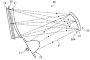
本実施形態に係るヘッドアップディスプレイ装置1は、図1に示すように、例えば自動車等の車両(不図示)のダッシュボード(不図示)の内側に配置され、ウインドシールド101に表示画像を投影するものである。ヘッドアップディスプレイ装置1は、ウインドシールド101に表示画像を投影して、ドライバ200のアイポイント201の前方に虚像110を表示する。アイポイント201は、運転席(不図示)に着座したドライバ200の視点位置として予め定められた位置である。ドライバ200は、ウインドシールド101によって反射された画像を虚像110として認識する。虚像110は、ドライバ200にとって、ウインドシールド101よりも前方に認識される。ヘッドアップディスプレイ装置1は、拡大ミラー2と、表示ユニット3とを含んで構成される。拡大ミラー2は、表示ユニット3から出射される表示光をウインドシールド101に向けて反射する。拡大ミラー2は、例えば非球面ミラーで構成される。表示ユニット3は、表示画像に対応する表示光を出射する。表示ユニット3は、液晶パネル10と、バックライトユニット20とを含んで構成される。
The head-up
液晶パネル10は、液晶表示素子である。液晶パネル10は、例えば光透過型または光半透過型のTFT液晶(Thin Film Transistor Liquid Crystal Display)等から成る。液晶パネル10は、車両に搭載された制御部(不図示)からの制御指示に応じて数字や文字、図形等を含む表示画像を表示する。
The
バックライトユニット20は、液晶パネル10に対して背面側から光を照射する。バックライトユニット20は、車両内の電源(不図示)から得られる直流電力により駆動する。バックライトユニット20は、図2に示すように、光源21と、集光部材23と、マイクロミラーアレイ25と、拡散板30とを含んで構成される。
The
光源21は、一つの発光ダイオード(LED:Light Emitting Diode)で構成される。LEDは、例えば車両内の電源から得られる直流電力により駆動する。LEDは、制御部からのON/OFF信号に応じて、点灯/消灯する。LEDは、例えば不図示の基板等に固定されている。基板は、裏側にヒートシンク(不図示)が固定されていてもよい。ヒートシンクは、基板に蓄積された熱をバックライトユニット20の外部に放出するものである。
The
集光部材23は、光源21から出射された光を集光するものである。集光部材23は、例えば集光レンズである。半球面のレンズ面23aを備えた半球状のレンズ本体部23bと、レンズ本体部23bの外周に沿って設けられたフランジ部23cとで構成される。
The
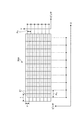
マイクロミラーアレイ25は、光学部材である。マイクロミラーアレイ25は、例えばガラスや透明樹脂で構成されている。マイクロミラーアレイ25は、凹状の反射面26Aを有し、集光部材23から入射する光を反射面26Aにより液晶パネル10に向けて反射する。マイクロミラーアレイ25は、反射面26Aが複数の微小ミラー27で構成される。マイクロミラーアレイ25は、いわゆるフライアイレンズと同様の形状を有する。ここでフライアイレンズとは、複数のレンズを格子状に配列したレンズ体である。複数の微小ミラー27は、反射面26Aに格子状に配列されている。複数の微小ミラー27は、図3に示すように、例えば反射面26AにおけるX方向およびX方向に直交するY方向に複数配列されている。各微小ミラー27は凸状の曲面である。
The
拡散板30は、シート状または薄板状に形成されており、マイクロミラーアレイ25と液晶パネル10との間の光路上に配置される。拡散板30は、マイクロミラーアレイ25により反射した光11を液晶パネル10に向けて拡散させるものである。
The
次に、バックライトユニット20の作用について図2〜図5,図6(A)〜図6(C)を参照して説明する。図2に示すように、光源21から出射した光は、入射側から集光部材23に入射する。集光部材23内を通過した光は、集光部材23のレンズ面23aから出射する。集光部材23のレンズ面23aから出射した光11は、マイクロミラーアレイ25上に集光される。集光部材23により集光されマイクロミラーアレイ25に入射する光11は、平行光であってもよいし、発散光や収束光であってもよい。例えば、集光部材23からマイクロミラーアレイ25に入射する光11を発散光にした場合、集光部材23をマイクロミラーアレイ25よりも小さくすることでき、かつ光路長を短くすることができる。
Next, the operation of the
マイクロミラーアレイ25に入射した光は、反射面26Aにより液晶パネル10側に向けて偏光する。マイクロミラーアレイ25は、図2に示すように、集光部材23から入射する光(入射光)11に対する液晶パネル10への反射光の偏角量がαとなる位置に配置される。本実施形態における偏角量αは、偏角量αが大きい場合、輝度ムラが生じ易くなることから、40°以下となることが好ましい。本実施形態における反射面26Aは、マイクロミラーアレイ25に入射する光11が液晶パネル10上に集光するように、凹状の形状が決定されることが好ましい。反射面26Aにより照明される範囲の大きさは、ヘッドアップディスプレイ装置1の光学系により作られるアイボックス(不図示)の像の大きさより大きいことが好ましい。アイボックスは、アイポイント201を含み、ドライバ200が虚像110を視認することができる空間領域である。反射面26Aを構成する複数の微小ミラー27は、図4に示すように、入射する光11により、反射面26Aと反対側の面の近傍に光源像12を形成する。微小ミラー27は、各光源像12からの光が液晶パネル10全面を照射するように、凸状の曲面の形状が決定されることが好ましい。また、微小ミラー27は、各光源像12からの光が液晶パネル10の全面を照射し、かつ液晶パネル10を照射しない光が小さくなるように、後述する曲面の曲率、ピッチ、ミラー幅、およびミラー高さ等が決定されることが好ましい。例えば、液晶パネル10が長方形の形状を有する場合、微小ミラー27の正面視の形状が長方形となる。
Light incident on the
本実施形態における微小ミラー27は、正面視において長方形状をしている。微小ミラー27は、X方向に長さxの長辺を有し、Y方向に長さyの短辺を有する。言い換えると、微小ミラー27は、X方向に長さxのミラー幅を有し、Y方向に長さyのミラー高さを有する。本実施形態における微小ミラー27は、X方向において同一の長さのミラー幅を有し、かつY方向において同一の長さのミラー高さを有する。なお、微小ミラー27は、ミラー幅xとミラー高さyとが同一の長さであってもよい。
The
本実施形態における微小ミラー27は、X方向において同一のピッチPxを有し、かつY方向において同一のピッチPyを有する。ここでピッチP(Px,Py)は、2つの隣接する微小ミラー27の中心点間の距離である。図3に示す縦軸をピッチとし、横軸をX方向とするグラフにおいて、複数の微小ミラー27のうち、X方向に配列された微小ミラー27のピッチPxは一定となる。さらに、図3に示す縦軸をY方向とし、横軸をピッチとするグラフでは、複数の微小ミラー27のうち、Y方向に配列された微小ミラー27のピッチPyは一定となる。
The micro mirrors 27 in the present embodiment have the same pitch Px in the X direction and have the same pitch Py in the Y direction. Here, the pitch P (Px, Py) is the distance between the center points of two
本実施形態における微小ミラー27は、図5に示すように、凸状の部分球面である。微小ミラー27は、X方向およびY方向において、同一の曲率半径Rを有する。曲率は、曲率半径Rの逆数であることから、微小ミラー27は、X方向において同一の曲率1/Rを有し、かつY方向において同一の曲率1/Rを有する。例えば、図6(A)に示す曲率半径R1の微小ミラー27は、曲率が1/R1である。
As shown in FIG. 5, the
本実施形態における微小ミラー27は、X方向において同一の発散角φを有し、Y方向において同一の発散角φを有する。発散角φは、図2に示すように、微小ミラー27が反射する光の光軸に対する拡がる角度である。微小ミラー27の発散角φは、図6(A)および図6(B)に示すように、同一のピッチP1を有する場合、曲率半径RがR1<R2の関係にあるときには、φ1>φ2となる。すなわち、発散角φは、また、発散角φは、図6(A)および図6(C)に示すように、同一の曲率半径R1を有する場合、ピッチPがP1<P2のときには、φ1<φ3となる。このように、微小ミラー27の発散角φは、ピッチPが大きくなると大きくなり、ピッチPが小さくなると小さくなる。発散角φは、大きくなるとバックライトユニット20の輝度ムラが生じ易くなることから、全角で50°以下となることが好ましい。
The
以上説明したように、本実施形態に係るバックライトユニット20は、光源21と、光源21から出射された光を集光する集光部材23と、凹状の反射面26Aを有し、集光部材23から入射する光11を反射面26Aにより液晶パネル10に向けて反射するマイクロミラーアレイ25と、マイクロミラーアレイ25と液晶パネル10との間の光路上に配置された拡散板30とを備える。マイクロミラーアレイ25は、反射面26Aが複数の微小ミラー27で構成される。複数の微小ミラー27は、反射面26AにおけるX方向およびY方向に複数配列される。各微小ミラー27は凸状の曲面である。
As described above, the
また、本実施形態に係るヘッドアップディスプレイ装置1は、光透過型の液晶パネル10と、バックライトユニット20とを少なくとも備える。バックライトユニット20は、光源21と、光源21から出射された光11を集光する集光部材23と、凹状の反射面26Aを有し、集光部材23から入射する光11を反射面26Aにより液晶パネル10に向けて反射するマイクロミラーアレイ25と、マイクロミラーアレイ25と液晶パネル10との間の光路上に配置された拡散板30とを有する。マイクロミラーアレイ25は、反射面26Aが複数の微小ミラー27で構成される。複数の微小ミラー27は、反射面26AにおけるX方向およびY方向に複数配列される。各微小ミラー27は凸状の曲面である。
Further, the head-up
上記構成を有するバックライトユニット20およびヘッドアップディスプレイ装置1によれば、マイクロミラーアレイ25を用いて、少ない部品構成で液晶パネル10の全面を照明することができるので、部品点数を削減し低コスト化を図ることができる。さらに、レンズアレイの後に集光レンズ等が不要となり、部品点数を削減することができる。また、光源からの光を平行にする平行光生成手段が不要となるので、部品点数を削減し、かつユニット全体を小型化することができる。また、マイクロミラーアレイ25を用いて複数の光源像12を形成し、各光源像12が液晶パネル10の全面を照明するので、光の利用効率が上がり、バックライトユニット20の輝度ムラを低減することができる。また、従来は、液晶パネル10の全面を照明するために、レンズアレイの大きさと複数の光源とが必要であったが、マイクロミラーアレイ25により複数の光源像12を形成することができるので、光源の削減および光学系の小型化を図ることができる。さらに、複数の光源を使用する場合、光が重なる部分で輝度ムラが生じていたが、一つの光源21での照明が可能となるので、消費電力を低減すると共に、輝度ムラを低減することが可能となる。
According to the
なお、本実施形態に係るマイクロミラーアレイ25は、微小ミラー27が凸状の曲面であるが、これに限定されるものではない。例えば、マイクロミラーアレイ25は、図7に示すように、微小ミラー37が凹状の曲面であってもよい。複数の微小ミラー37は、反射面26BにおけるX方向およびY方向に複数に配列される。
In the
また、本実施形態に係るバックライトユニット20は、マイクロミラーアレイ25と液晶パネル10との間の光路上に拡散板30が配置されているが、これに限定されるものではない。例えば、バックライトユニット20は、上記構成に加えて、収差補正レンズ31を含んで構成してもよい。収差補正レンズ31は、図8に示すように、マイクロミラーアレイ25と拡散板30との間の光路上に配置される。収差補正レンズ31は、バックライトユニット20内の光学系の収差を補正するものである。なお、収差補正レンズ31は、デフォーカス補正を行うためのレンズやミラー等であってもよい。
Further, in the
また、本実施形態に係るバックライトユニット20は、マイクロミラーアレイ25と拡散板30との間の光路上に配置され、マイクロミラーアレイ25から反射された光を液晶パネル10に向けて偏光する反射ミラー32を含んで構成してもよい。反射ミラー32は、例えば平面ミラーである。上記構成により、光源21から液晶パネル10までの光路をより短くすることが可能となり、ユニット自体を小型化することが可能となる。
Further, the
[第2実施形態]
次に、第2実施形態に係るバックライトユニットおよびヘッドアップディスプレイ装置について説明する。図11は、第2実施形態に係るマイクロミラーアレイの正面図である。図12は、第2実施形態に係るマイクロミラーアレイの正面図である。図13は、第2実施形態の変形例に係るマイクロミラーアレイの正面図である。
[Second embodiment]
Next, a backlight unit and a head-up display device according to a second embodiment will be described. FIG. 11 is a front view of the micro mirror array according to the second embodiment. FIG. 12 is a front view of the micro mirror array according to the second embodiment. FIG. 13 is a front view of a micromirror array according to a modification of the second embodiment.
第2実施形態に係るバックライトユニット20およびヘッドアップディスプレイ装置1は、微小ミラー27が同一の曲率1/Rを有し、同一の曲率1/Rを有する方向における長さが異なる点で上記第1実施形態と異なる。なお、以下の実施形態では、上記第1実施形態と同様の構成要素には共通の符号を付すと共に、共通する構成、作用、効果について重複した説明はできるだけ省略する。
The
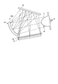
本実施形態におけるマイクロミラーアレイ25は、反射面26Cが複数の微小ミラー27で構成される。各微小ミラー27は、凸状の曲面が、X方向およびY方向の少なくとも一つの方向において、同一の曲率1/Rを有し、同一の曲率1/Rを有する方向における長さが、異なるように形成される。微小ミラー27は、例えば、図11に示すように、同一の曲率1/Rを有するX方向における長さ(ミラー幅)xa,xb,xcが、異なるように形成される。すなわち、微小ミラー27は、同一の曲率1/Rを有するX方向におけるピッチPxが、異なるように形成される。一方、同一の曲率1/Rを有するY方向における長さ(ミラー高さ)yが、同一になるように形成される。言い換えると、微小ミラー27は、同一の曲率1/Rを有するY方向におけるピッチPyが、同一になるように形成される。一方、微小ミラー27は、例えば、図12に示すように、同一の曲率1/Rを有するY方向における長さ(ミラー高さ)ya,yb,ycが、異なるように形成される。すなわち、微小ミラー27は、同一の曲率1/Rを有するY方向におけるピッチPyが、異なるように形成される。一方、同一の曲率1/Rを有するX方向における長さ(ミラー幅)xが、同一になるように形成される。言い換えると、微小ミラー27は、同一の曲率1/Rを有するX方向におけるピッチPxが、同一になるように形成される。
In the
以上説明したように、本実施形態に係るバックライトユニット20およびヘッドアップディスプレイ装置1は、微小ミラー27の曲面が、X方向およびY方向の少なくとも一つの方向において、同一の曲率1/Rを有し、同一の曲率1/Rを有する方向における長さが、異なるように形成される。これにより、上記第1実施形態におけるバックライトユニット20およびヘッドアップディスプレイ装置1と同様の効果を得ることが可能となる。微小ミラー27は液晶パネル10の全面を照らすように設計される。しかしながら、微小ミラー27と液晶パネル10との距離は、例えば反射面26Cの一端と他端とでは異なることから、微小ミラー27を同じような光の広げ方にすると距離が遠い方が暗くなり、距離が近い方が明るくなり、バックライトユニット20に輝度ムラが生じる。そこで、微小ミラー27の曲面の曲率1/Rを一定にした場合、距離が短い位置の微小ミラー27に対して、同一の曲率1/Rを有する方向における長さまたはピッチPを大きくする一方、距離が長い位置の微小ミラー27に対して、同一の曲率1/Rを有する方向における長さまたはピッチPを小さくする。長さまたはピッチPが大きい微小ミラー27の発散角φが大きくなることで、照明範囲が広くなり、ピッチPが小さい微小ミラー27の発散角φが小さくなることで、照明範囲が狭くなるので、液晶パネル10の全面をバランスよく照明することができ、輝度ムラを低減することができる。
As described above, in the
なお、本実施形態に係る微小ミラー27は、同一の曲率1/Rを有する方向における長さまたはピッチPが、反射面26Cを同一の曲率1/Rを有する方向において分割した領域ごとに異なるように形成されていてもよい。微小ミラー27は、例えば、図11に示すように、同一の曲率1/Rを有するX方向における長さまたはピッチPが、反射面26CをX方向において分割した領域Ax,Bx,Cxごとに異なるように形成される。すなわち、領域Axにおける微小ミラー27は、同一の長さxaまたは同一のピッチPxaを有する。領域Bxにおける微小ミラー27は、同一の長さxbまたは同一のピッチPxbを有する。領域Cxにおける微小ミラー27は、同一の長さxcまたは同一のピッチPxcを有する。本実施形態における長さxa,xb,xcは、例えばxa<xb=xcの関係がある。本実施形態におけるPxa,Pxb,Pxcは、例えばPxa<Pxb=Pxcの関係がある。一方、微小ミラー27は、例えば、図12に示すように、同一の曲率1/Rを有するY方向における長さまたはピッチPが、反射面26DをY方向において分割した領域Ay,By,Cyごとに異なるように形成される。領域Ayにおける微小ミラー27は、同一の長さyaまたは同一のピッチPyaを有する。領域Byにおける微小ミラー27は、同一の長さybまたは同一のピッチPybを有する。領域Cyにおける微小ミラー27は、同一の長さycまたは同一のピッチPycを有する。本実施形態におけるya,yb,ycは、例えばya>yb>ycの関係がある。本実施形態におけるPya,Pyb,Pycは、Pya>Pyb>Pycの関係がある。
In the
上記構成を有する本実施形態の変形例に係るバックライトユニット20およびヘッドアップディスプレイ装置1は、各微小ミラー27において、同一の曲率1/Rを有する方向における長さが、反射面26C,26Dを同一の曲率1/Rを有する方向において分割した領域ごとに異なるように形成される。これにより、上記と同様の効果を得ることができると共に、微小ミラー27の長さまたはピッチを個別に設計する必要がなくなり、設計工数を簡略化することができる。
In the
また、本実施形態に係る各微小ミラー27は、同一の曲率1/Rを有する方向における長さが、連続して異なるように形成されていてもよい。微小ミラー27は、例えば、図13に示すように、反射面26Eにおける同一の曲率1/Rを有するX方向、Y方向における長さxa,xb,・・・、長さya,yb,・・・が、異なるように形成される。言い換えると、微小ミラー27は、同一の曲率1/Rを有するX方向、Y方向におけるピッチPxa,Pxb,・・・、ピッチPya,Pyb,・・・が、異なるように形成される。なお、微小ミラー27は、ミラー幅x、ミラー高さy、ピッチPは、連続して異なるように形成される場合、線形に異なるように設定されてもよいし、非線形に異なるように設定されてもよい。
Further, each micromirror 27 according to the present embodiment may be formed so that the lengths in the direction having the
上記構成を有する本実施形態の変形例に係るバックライトユニット20およびヘッドアップディスプレイ装置1は、各微小ミラー27において、同一の曲率1/Rを有する方向における長さが、連続して異なるように形成されるので、上記と同様の効果を得ることが可能となる。
The
[第3実施形態]
次に、第3実施形態に係るバックライトユニットおよびヘッドアップディスプレイ装置について説明する。図14は、第3実施形態に係る微小ミラーの斜視図である。図15は、第3実施形態に係るマイクロミラーアレイの発散角の差を説明するための模式図である。
[Third embodiment]
Next, a backlight unit and a head-up display device according to a third embodiment will be described. FIG. 14 is a perspective view of a micro mirror according to the third embodiment. FIG. 15 is a schematic diagram for explaining the difference in the divergence angle of the micromirror array according to the third embodiment.
第3実施形態に係るバックライトユニット20およびヘッドアップディスプレイ装置1は、微小ミラー27がX方向およびY方向の少なくとも一つの方向における長さが同一であり、同一の長さを有する方向における曲面の曲率1/Rが異なる点で上記第1実施形態と異なる。
In the
本実施形態におけるマイクロミラーアレイ25は、反射面26Fが複数の微小ミラー27で構成される。各微小ミラー27は、X方向およびY方向の少なくとも一つの方向における長さが同一であり、凸状の曲面が、同一の長さを有する方向において、異なるように形成される。各微小ミラー27間には、段差28が設けられている。
In the
以上説明したように、本実施形態に係るバックライトユニット20およびヘッドアップディスプレイ装置1は、各微小ミラー27のX方向およびY方向の少なくとも一つの方向における長さが同一であり、曲面の曲率1/Rが、同一の長さを有する方向において、異なるように形成される。これにより、上記第1実施形態におけるバックライトユニット20およびヘッドアップディスプレイ装置1と同様の効果を得ることができる。微小ミラー27のX方向およびY方向の少なくとも一つの方向における長さまたはピッチPを同一にした場合、距離が短い位置の微小ミラー27に対して、曲率1/Rを小さくする一方、距離が長い位置の微小ミラー27に対して、曲率1/Rを大きくする。曲率1/Rが大きい(すなわち、曲率半径Rが小さい)微小ミラー27の発散角φが大きくなることで、照明範囲が広くなり、曲率1/Rが小さい(すなわち、曲率半径Rが大きい)微小ミラー27の発散角φが小さくなることで、照明範囲が狭くなるので、液晶パネル10の全面をバランスよく照明することができ、輝度ムラを低減することができる。
As described above, in the
なお、本実施形態に係る微小ミラー27は、同一の長さを有する方向における曲面の曲率1/Rが、反射面26Fを同一の長さを有する方向において分割した領域ごとに異なるように形成されていてもよい。微小ミラー27は、例えば、図15に示すように、同一の長さまたはピッチPを有するX方向における曲率1/Rが、反射面26FをX方向において分割した領域Ax,Bx,Cxごとに異なるように形成される。微小ミラー27は、領域Axにおいて、同一の曲率1/Raを有する。微小ミラー27は、領域Bxにおいて、同一の曲率1/Rbを有する。微小ミラー27は、領域Cxにおいて、同一の曲率1/Rcを有する。領域Bx(または領域Cx)における微小ミラー27は、図15に示すように、例えば液晶パネル10の一方の端部までの距離が遠いので発散角φb1が小さくなるが、液晶パネル10の他方の端部までの距離が近いので発散角φb2が大きくなる。一方、領域Axにおける微小ミラー27は、φb1≒φb2となる。そこで、例えば、領域Axにおける微小ミラー27の曲率1/Raを一定にし、領域Bx,Cxにおける微小ミラー27の曲率1/Rb,1/Rcを、曲率1/Raに対して小さくするように形成することが好ましい。また、領域Bx,Cxにおける微小ミラー27は、X方向において、領域Axとは反対側の端部に向けて、曲率1/Rb,1/Rcが連続して小さくなるように形成してもよい。なお、微小ミラー27は、同一の長さまたはピッチPを有するY方向における曲率1/Rが、反射面26FをY方向において分割した領域ごとに異なるように形成されていてもよいし、X方向およびY方向に分割した領域ごとに形成されていてもよい。上記構成により、上記と同様の効果を得ることができると共に、液晶パネル10に向かう光の量を増やすことができ、光の利用効率を上げることができる。さらに、微小ミラー27の曲率1/Rを個別に設計する必要がなくなり、設計工数を簡略化することができる。
The
また、本実施形態に係る微小ミラー27は、X方向およびY方向の少なくとも一つの方向における長さが同一であり、曲面が複数の曲率1/Rを有する自由曲面であってもよい。この複数の曲率1/Rが、同一の長さを有する方向において、集光部材23からの入射光に対する液晶パネル10への反射光の偏角量αに応じて、異なるように形成されてもよい。微小ミラー27は、例えば、偏角量αが大きい場合には、曲率1/Rが大きくなる一方、偏角量αが小さい場合には、曲率1/Rが小さくする。上記構成により、上記と同様の効果を得ることができる。
Further, the
なお、上記第1〜第3実施形態および変形例では、微小ミラー27は、長方形状をしているが、これに限定されず、正方形状、円形状、六角形状であってもよい。微小ミラー27の形状は、上述したように、液晶パネル10の形状に合わせて決定されることが好ましい。
In the first to third embodiments and the modifications, the
また、上記第1〜第3実施形態および変形例では、ヘッドアップディスプレイ装置1において、表示画像の投影対象がウインドシールド101であったが、これに限定されず、例えばコンバイナ等であってもよい。
In the first to third embodiments and the modifications, the
また、上記第1〜第3実施形態および変形例では、ヘッドアップディスプレイ装置1を車両に適用した場合について説明したが、これに限定されるものではなく、車両以外の乗り物、例えば船舶や航空機等に適用してもよい。
Further, in the first to third embodiments and the modified examples, the case where the head-up
また、上記第1〜第3実施形態および変形例では、光源21は、一つの発光ダイオードで構成されるが、これに限定されるものではなく、例えば複数の発光ダイオードが一つにまとめられたものであってもよい。また、光源21は、高輝度の光を発光するものであればよく、発光ダイオードに限定されるものではない。
In the first to third embodiments and the modifications, the
1 ヘッドアップディスプレイ装置
2 拡大ミラー
3 表示ユニット
10 液晶パネル
11 光
12 光源像
20 バックライトユニット
21 光源
23 集光部材
25 マイクロミラーアレイ
26A,26B,26C,26D,26E,26F 反射面
27,37 微小ミラー
28 段差
30 拡散板
31 収差補正レンズ
32 反射ミラー
101 ウインドシールド
110 虚像
200 ドライバ
201 アイポイント
DESCRIPTION OF
Claims (8)
前記光源から出射された光を集光する集光部材と、
凹状の反射面を有し、前記集光部材から入射する光を前記反射面により光透過型の液晶表示素子に向けて反射する光学部材と、
前記光学部材と前記液晶表示素子との間の光路上に配置された拡散板と、
を備え、
前記光学部材は、
前記反射面が複数の微小ミラーで構成され、
複数の前記微小ミラーは、
前記反射面における第1方向および前記第1方向と直交する第2方向に複数配列され、
各前記微小ミラーは、
凸状または凹状の曲面である、
ことを特徴とするバックライトユニット。 At least one light source;
A light-collecting member that collects light emitted from the light source,
An optical member having a concave reflecting surface, and reflecting light incident from the light-collecting member toward the light-transmitting liquid crystal display element by the reflecting surface;
A diffusion plate disposed on an optical path between the optical member and the liquid crystal display element,
With
The optical member,
The reflection surface is constituted by a plurality of micro mirrors,
The plurality of micro mirrors,
A plurality of the reflection surfaces are arranged in a first direction and a second direction orthogonal to the first direction;
Each of the micromirrors is
A convex or concave curved surface,
A backlight unit characterized in that:
前記曲面が、前記第1方向および前記第2方向の少なくとも一つの方向において、同一の曲率を有し、
同一の前記曲率を有する方向における長さが、互いに異なるように形成される、
請求項1に記載のバックライトユニット。 Each of the micromirrors is
The curved surface has the same curvature in at least one of the first direction and the second direction,
Lengths in the direction having the same curvature are formed to be different from each other ,
The backlight unit according to claim 1.
前記曲面が、前記第1方向および前記第2方向の少なくとも一つの方向において、同一の曲率を有し、
同一の曲率を有する方向における長さが、前記反射面を同一の前記曲率を有する方向において分割した領域ごとに異なるように形成される、
請求項1に記載のバックライトユニット。 Each of the micromirrors is
The curved surface has the same curvature in at least one of the first direction and the second direction,
The length in the direction having the same curvature is formed so as to be different for each region obtained by dividing the reflection surface in the direction having the same curvature.
The backlight unit according to claim 1 .
前記曲面が、前記第1方向および前記第2方向の少なくとも一つの方向において、同一の曲率を有し、
同一の曲率を有する方向における長さが、連続して異なるように形成される、
請求項1に記載のバックライトユニット。 Each of the micromirrors is
The curved surface has the same curvature in at least one of the first direction and the second direction,
The length in the direction having the same curvature is formed to be continuously different,
The backlight unit according to claim 1 .
前記第1方向および前記第2方向の少なくとも一つの方向における長さが同一であり、
前記曲面の曲率が、同一の長さを有する方向において、互いに異なるように形成される、
請求項1に記載のバックライトユニット。 Each of the micromirrors is
The length in at least one of the first direction and the second direction is the same,
The curvature of the curved surface is formed to be different from each other in a direction having the same length,
The backlight unit according to claim 1.
前記第1方向および前記第2方向の少なくとも一つの方向における長さが同一であり、
同一の長さを有する方向における前記曲面の曲率が、前記反射面を同一の長さを有する方向において分割した領域ごとに異なるように形成される、
請求項1に記載のバックライトユニット。 Each of the micromirrors is
The length in at least one of the first direction and the second direction is the same,
The curvature of the curved surface in the direction having the same length is formed so as to be different for each region obtained by dividing the reflection surface in the direction having the same length.
The backlight unit according to claim 1 .
前記第1方向および前記第2方向の少なくとも一つの方向における長さが同一であり、
前記曲面が複数の曲率を有する自由曲面であり、
複数の曲率が、同一の長さを有する方向において、前記集光部材からの入射光に対する前記液晶表示素子への反射光の偏角量に応じて、異なるように形成される、
請求項1に記載のバックライトユニット。 Each of the micromirrors is
The length in at least one of the first direction and the second direction is the same,
The curved surface is a free-form surface having a plurality of curvatures,
A plurality of curvatures are formed differently in a direction having the same length, in accordance with an amount of declination of reflected light to the liquid crystal display element with respect to incident light from the light collecting member,
The backlight unit according to claim 1.
バックライトユニットと、
を少なくとも備え、
前記バックライトユニットは、
少なくとも一つの光源と、
前記光源から出射された光を集光する集光部材と、
凹状の反射面を有し、前記集光部材から入射する光を前記反射面により前記液晶表示素子に向けて反射する光学部材と、
前記光学部材と前記液晶表示素子との間の光路上に配置された拡散板と、
を有し、
前記光学部材は、
前記反射面が複数の微小ミラーで構成され、
複数の前記微小ミラーは、
前記反射面における第1方向および前記第1方向と直交する第2方向に複数配列され、
各前記微小ミラーは、
凸状または凹状の曲面である、
ことを特徴とするヘッドアップディスプレイ装置。 A light transmission type liquid crystal display element,
A backlight unit,
At least,
The backlight unit includes:
At least one light source;
A light-collecting member that collects light emitted from the light source,
An optical member having a concave reflecting surface and reflecting light incident from the light collecting member toward the liquid crystal display element by the reflecting surface;
A diffusion plate disposed on an optical path between the optical member and the liquid crystal display element,
Has,
The optical member,
The reflection surface is constituted by a plurality of micro mirrors,
The plurality of micro mirrors,
A plurality of the reflection surfaces are arranged in a first direction and a second direction orthogonal to the first direction;
Each of the micromirrors is
A convex or concave curved surface,
A head-up display device characterized by the above-mentioned.
Priority Applications (4)
| Application Number | Priority Date | Filing Date | Title |
|---|---|---|---|
| JP2017170942A JP6663890B2 (en) | 2017-09-06 | 2017-09-06 | Backlight unit and head-up display device |
| DE102018214817.1A DE102018214817B4 (en) | 2017-09-06 | 2018-08-31 | Backlight unit and head-up display device |
| US16/120,678 US10379398B2 (en) | 2017-09-06 | 2018-09-04 | Backlight unit and head-up display device |
| CN201811031169.8A CN109581734B (en) | 2017-09-06 | 2018-09-05 | Backlight unit and head-up display device |
Applications Claiming Priority (1)
| Application Number | Priority Date | Filing Date | Title |
|---|---|---|---|
| JP2017170942A JP6663890B2 (en) | 2017-09-06 | 2017-09-06 | Backlight unit and head-up display device |
Publications (2)
| Publication Number | Publication Date |
|---|---|
| JP2019045780A JP2019045780A (en) | 2019-03-22 |
| JP6663890B2 true JP6663890B2 (en) | 2020-03-13 |
Family
ID=65363678
Family Applications (1)
| Application Number | Title | Priority Date | Filing Date |
|---|---|---|---|
| JP2017170942A Active JP6663890B2 (en) | 2017-09-06 | 2017-09-06 | Backlight unit and head-up display device |
Country Status (4)
| Country | Link |
|---|---|
| US (1) | US10379398B2 (en) |
| JP (1) | JP6663890B2 (en) |
| CN (1) | CN109581734B (en) |
| DE (1) | DE102018214817B4 (en) |
Families Citing this family (7)
| Publication number | Priority date | Publication date | Assignee | Title |
|---|---|---|---|---|
| US11002966B2 (en) * | 2017-05-04 | 2021-05-11 | Google Llc | Systems, devices, and methods for eyebox expansion in wearable heads-up display |
| US11092803B2 (en) * | 2019-06-08 | 2021-08-17 | E-Lead Electronic Co., Ltd. | Head-up display device with reflecting target diffuser sheet |
| CN112578593B (en) * | 2019-09-30 | 2023-05-16 | 宁波舜宇车载光学技术有限公司 | Lighting device, display and lighting method |
| DE102021113083A1 (en) | 2021-05-20 | 2022-11-24 | E-Lead Electronic Co., Ltd. | Directional backlit display device |
| TWI783622B (en) * | 2021-08-12 | 2022-11-11 | 怡利電子工業股份有限公司 | Directivity backlight display device with reflector curvature assisted diffuser |
| DE102021121164A1 (en) | 2021-08-13 | 2023-02-16 | E-Lead Electronic Co., Ltd. | Directional backlit display with diffuser supporting reflector curvature |
| TWI788049B (en) | 2021-10-13 | 2022-12-21 | 怡利電子工業股份有限公司 | Directional backlit display device with eye tracking |
Family Cites Families (18)
| Publication number | Priority date | Publication date | Assignee | Title |
|---|---|---|---|---|
| JPH09222583A (en) * | 1996-02-16 | 1997-08-26 | Asahi Glass Co Ltd | Holographic display device |
| JPH11297112A (en) * | 1998-04-15 | 1999-10-29 | Matsushita Electron Corp | Bulb with reflector |
| US6195201B1 (en) * | 1999-01-27 | 2001-02-27 | Svg Lithography Systems, Inc. | Reflective fly's eye condenser for EUV lithography |
| US7212347B2 (en) * | 2003-12-08 | 2007-05-01 | Jds Uniphase Corporation | Reflective illumination system |
| US20060038188A1 (en) * | 2004-08-20 | 2006-02-23 | Erchak Alexei A | Light emitting diode systems |
| JP5992302B2 (en) * | 2012-11-27 | 2016-09-14 | 日東電工株式会社 | Display device |
| JP6056680B2 (en) * | 2013-06-25 | 2017-01-11 | 株式会社デンソー | Head-up display device |
| US20150205135A1 (en) * | 2014-01-21 | 2015-07-23 | Osterhout Group, Inc. | See-through computer display systems |
| DE112015002814B4 (en) * | 2014-06-13 | 2022-04-07 | Mitsubishi Electric Corporation | Virtual image display device |
| JP6365174B2 (en) | 2014-09-24 | 2018-08-01 | 日本精機株式会社 | Head-up display device |
| US20170299922A1 (en) | 2014-09-24 | 2017-10-19 | Nippon Seiki Co., Ltd. | Head-up display device |
| JP2016065907A (en) * | 2014-09-24 | 2016-04-28 | 日本精機株式会社 | Head-up display device |
| CN204730067U (en) * | 2015-06-02 | 2015-10-28 | 上海理工大学 | The car headlamp of distance-light one |
| JP6807177B2 (en) * | 2016-07-05 | 2021-01-06 | リコーインダストリアルソリューションズ株式会社 | Reflective screen |
| JP2018205448A (en) * | 2017-05-31 | 2018-12-27 | セイコーエプソン株式会社 | Display device and illumination device |
| JP6663891B2 (en) * | 2017-09-06 | 2020-03-13 | 矢崎総業株式会社 | Backlight unit and head-up display device |
| JP2019045858A (en) * | 2017-09-06 | 2019-03-22 | 矢崎総業株式会社 | Backlight unit and head-up display device |
| JP6663896B2 (en) * | 2017-11-02 | 2020-03-13 | 矢崎総業株式会社 | Head-up display device |
-
2017
- 2017-09-06 JP JP2017170942A patent/JP6663890B2/en active Active
-
2018
- 2018-08-31 DE DE102018214817.1A patent/DE102018214817B4/en active Active
- 2018-09-04 US US16/120,678 patent/US10379398B2/en active Active
- 2018-09-05 CN CN201811031169.8A patent/CN109581734B/en active Active
Also Published As
| Publication number | Publication date |
|---|---|
| US20190072791A1 (en) | 2019-03-07 |
| JP2019045780A (en) | 2019-03-22 |
| CN109581734A (en) | 2019-04-05 |
| DE102018214817B4 (en) | 2023-11-23 |
| US10379398B2 (en) | 2019-08-13 |
| DE102018214817A1 (en) | 2019-03-07 |
| CN109581734B (en) | 2021-11-05 |
Similar Documents
| Publication | Publication Date | Title |
|---|---|---|
| JP6663890B2 (en) | Backlight unit and head-up display device | |
| JP6078798B2 (en) | Head-up display, lighting device, and moving body equipped with the same | |
| JP5866644B1 (en) | Head-up display and moving body with head-up display | |
| CN109946838B (en) | Head-up display device | |
| US10712617B2 (en) | Backlight unit and head-up display device | |
| JP6098375B2 (en) | Head-up display device | |
| WO2016047621A1 (en) | Head-up display device | |
| WO2016208378A1 (en) | Liquid crystal display device | |
| US10859754B2 (en) | LED light source device and electronic device using the same | |
| US10324336B2 (en) | Backlight unit and head-up display device | |
| EP3447561B1 (en) | Head-up display device | |
| TWI465768B (en) | Head-up display (hud) | |
| JP6365174B2 (en) | Head-up display device | |
| KR20140008425A (en) | Head-up display device | |
| JP6550923B2 (en) | Display device | |
| JP2018018706A (en) | Luminaire and headup display device | |
| JP2016065907A (en) | Head-up display device | |
| JP2018180291A (en) | Display device for vehicles | |
| JP7357233B2 (en) | heads up display | |
| JPWO2018139157A1 (en) | Illumination device and head-up display device | |
| WO2023153510A1 (en) | Optical member, light source device, and head-up display | |
| KR20140006332A (en) | Back light unit for head up display |
Legal Events
| Date | Code | Title | Description |
|---|---|---|---|
| A621 | Written request for application examination |
Free format text: JAPANESE INTERMEDIATE CODE: A621 Effective date: 20190117 |
|
| A131 | Notification of reasons for refusal |
Free format text: JAPANESE INTERMEDIATE CODE: A131 Effective date: 20191203 |
|
| A977 | Report on retrieval |
Free format text: JAPANESE INTERMEDIATE CODE: A971007 Effective date: 20191129 |
|
| A521 | Request for written amendment filed |
Free format text: JAPANESE INTERMEDIATE CODE: A523 Effective date: 20200122 |
|
| TRDD | Decision of grant or rejection written | ||
| A01 | Written decision to grant a patent or to grant a registration (utility model) |
Free format text: JAPANESE INTERMEDIATE CODE: A01 Effective date: 20200212 |
|
| A61 | First payment of annual fees (during grant procedure) |
Free format text: JAPANESE INTERMEDIATE CODE: A61 Effective date: 20200217 |
|
| R150 | Certificate of patent or registration of utility model |
Ref document number: 6663890 Country of ref document: JP Free format text: JAPANESE INTERMEDIATE CODE: R150 |
|
| R250 | Receipt of annual fees |
Free format text: JAPANESE INTERMEDIATE CODE: R250 |
|
| S531 | Written request for registration of change of domicile |
Free format text: JAPANESE INTERMEDIATE CODE: R313531 |
|
| R350 | Written notification of registration of transfer |
Free format text: JAPANESE INTERMEDIATE CODE: R350 |
|
| R250 | Receipt of annual fees |
Free format text: JAPANESE INTERMEDIATE CODE: R250 |