EP4480883A1 - Krankabel- und schlauchverwaltung - Google Patents
Krankabel- und schlauchverwaltung Download PDFInfo
- Publication number
- EP4480883A1 EP4480883A1 EP23188790.2A EP23188790A EP4480883A1 EP 4480883 A1 EP4480883 A1 EP 4480883A1 EP 23188790 A EP23188790 A EP 23188790A EP 4480883 A1 EP4480883 A1 EP 4480883A1
- Authority
- EP
- European Patent Office
- Prior art keywords
- cable
- reel
- hose
- trolley
- hoist
- Prior art date
- Legal status (The legal status is an assumption and is not a legal conclusion. Google has not performed a legal analysis and makes no representation as to the accuracy of the status listed.)
- Pending
Links
Images


Classifications
-
- B—PERFORMING OPERATIONS; TRANSPORTING
- B66—HOISTING; LIFTING; HAULING
- B66C—CRANES; LOAD-ENGAGING ELEMENTS OR DEVICES FOR CRANES, CAPSTANS, WINCHES, OR TACKLES
- B66C13/00—Other constructional features or details
- B66C13/12—Arrangements of means for transmitting pneumatic, hydraulic, or electric power to movable parts of devices
- B66C13/14—Arrangements of means for transmitting pneumatic, hydraulic, or electric power to movable parts of devices to load-engaging elements or motors associated therewith
-
- B—PERFORMING OPERATIONS; TRANSPORTING
- B66—HOISTING; LIFTING; HAULING
- B66C—CRANES; LOAD-ENGAGING ELEMENTS OR DEVICES FOR CRANES, CAPSTANS, WINCHES, OR TACKLES
- B66C13/00—Other constructional features or details
- B66C13/04—Auxiliary devices for controlling movements of suspended loads, or preventing cable slack
- B66C13/10—Auxiliary devices for controlling movements of suspended loads, or preventing cable slack for preventing cable slack
-
- B—PERFORMING OPERATIONS; TRANSPORTING
- B66—HOISTING; LIFTING; HAULING
- B66C—CRANES; LOAD-ENGAGING ELEMENTS OR DEVICES FOR CRANES, CAPSTANS, WINCHES, OR TACKLES
- B66C19/00—Cranes comprising trolleys or crabs running on fixed or movable bridges or gantries
-
- B—PERFORMING OPERATIONS; TRANSPORTING
- B66—HOISTING; LIFTING; HAULING
- B66C—CRANES; LOAD-ENGAGING ELEMENTS OR DEVICES FOR CRANES, CAPSTANS, WINCHES, OR TACKLES
- B66C9/00—Travelling gear incorporated in or fitted to trolleys or cranes
- B66C9/18—Travelling gear incorporated in or fitted to trolleys or cranes with means for locking trolleys or cranes to runways or tracks to prevent inadvertent movements
-
- F—MECHANICAL ENGINEERING; LIGHTING; HEATING; WEAPONS; BLASTING
- F16—ENGINEERING ELEMENTS AND UNITS; GENERAL MEASURES FOR PRODUCING AND MAINTAINING EFFECTIVE FUNCTIONING OF MACHINES OR INSTALLATIONS; THERMAL INSULATION IN GENERAL
- F16L—PIPES; JOINTS OR FITTINGS FOR PIPES; SUPPORTS FOR PIPES, CABLES OR PROTECTIVE TUBING; MEANS FOR THERMAL INSULATION IN GENERAL
- F16L3/00—Supports for pipes, cables or protective tubing, e.g. hangers, holders, clamps, cleats, clips, brackets
- F16L3/01—Supports for pipes, cables or protective tubing, e.g. hangers, holders, clamps, cleats, clips, brackets for supporting or guiding the pipes, cables or protective tubing, between relatively movable points, e.g. movable channels
- F16L3/012—Supports for pipes, cables or protective tubing, e.g. hangers, holders, clamps, cleats, clips, brackets for supporting or guiding the pipes, cables or protective tubing, between relatively movable points, e.g. movable channels using reels
-
- H—ELECTRICITY
- H02—GENERATION; CONVERSION OR DISTRIBUTION OF ELECTRIC POWER
- H02G—INSTALLATION OF ELECTRIC CABLES OR LINES, OR OF COMBINED OPTICAL AND ELECTRIC CABLES OR LINES
- H02G11/00—Arrangements of electric cables or lines between relatively-movable parts
- H02G11/02—Arrangements of electric cables or lines between relatively-movable parts using take-up reel or drum
Definitions
- Crane systems are systems for material handling equipment used to lift and move loads in industrial, construction, and manufacturing settings.
- Crane systems may include various cables and hoses for operation of the system.
- Festooning systems are known to be used to support, protect, and guide these cables and hoses as they move along the crane's structure. Festooning may prevent cable and hose entanglement, damage, or interference with the crane's movements.
- the festooning system allows the cables and hoses to smoothly move and adjust their length as the crane travels across the workspace or performs lifting and lowering operations.
- a crane system includes a beam, a trolley movable along the beam, and a hoist supported by the trolley.
- a cable and/or a hose is connected with at least one of the hoist, the trolley, or a load supported by the hoist.
- a management system for the cable and/or hose includes a reel mounted in a position fixed against lateral movement for receiving the cable or hose.
- a trough is mounted to the beam for supporting the cable or hose as the trolley moves along the beam.
- the trough can be V-shaped in cross-section.
- the trough can include ultra high molecular weight polyethylene.
- the cable or hose can be a pneumatic hose.
- the management system may include a guide post extending in a direction transverse to the beam for guiding the cable and/or hose into the trough.
- the reel can be substantially centrally located relative to the beam, and the trolley can move along the beam in a first direction away from the reel and in a second direction away from the reel, the second direction opposite the first direction, with the cable and/or hose remaining connected with the hoist, the trolley, and/or the load.
- the management system can include a load balancer includes a cable attached to the reel.
- the load balancer can be mounted in a position fixed against lateral movement, the load balancer includes a counterbalance.
- the cable extends from the counterbalance, and an end of the cable is attached to the reel.
- the cable can be attached to a cylinder extending from a barrel of the reel.
- the cylinder may include a helical groove for the cable to coil within.
- the load balancer can be mounted to the beam.
- the reel can be mounted to the beam.
- the beam may provide an enclosed track, and the trolley includes a pad spring loaded to contact an interior surface of the beam.
- a method of managing a hose or cable includes providing a trolley movable along a beam and a hoist supported by the trolley, mounting a reel in a position fixed against lateral movement, providing a hose or cable on the reel and connected with at least one of the hoist, the trolley, or a load supported by the hoist.
- the method includes mounting a trough to the beam for receiving the hose or cable, and attaching a load balancer cable to the reel.
- the step of attaching the load balancer cable to the reel may include attaching the load balancer cable to a cylinder extending from a barrel of the reel.
- the step of mounting the reel can include mounting the reel to the beam.
- the trough can be V-shaped in cross section.
- the method may include positioning a guide post, which includes a perch to direct the hose or cable into the trough.
- the positioning of the guide post step can include mounting the guide post to the beam.
- the step of attaching the load balancer cable to the reel may include attaching the load balancer cable to a cylinder extending from a barrel of the reel, and the step of mounting the reel includes mounting the reel to the beam.
- the method may include mounting a guide post to the beam, the guide post includes a perch to direct the hose or cable into the trough.
- This application relates to crane systems, and more particularly to hose or cable management systems and methods for crane systems.
- the systems and methods disclosed herein have been found to be improvements over prior art festooning systems and methods.
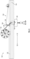
- Figure 1 illustrates an example crane system 20 including a beam 22, a trolley 24 movable along length of the beam 22 in directions D1 and D2, and a hoist 26 supported by the trolley 24.
- the beam 22 may provide a bridge or runway of the crane system 20 in some examples and provides a track for the trolley 24 to move along, such as to position the hoist 26 and/or load.
- the beam 22 may be arranged horizontally over a workspace in an industrial, construction, or manufacturing setting in some examples. Movement of the trolley 24 may be done manually and/or remotely in some examples.
- the trolley 24 may be motorized in some examples.
- a cable or a hose 28 may be connected with one or more of the trolley 24, the hoist 26, or the load supported by the hoist 26, such as to provide power and/or control to the hoist 26 the load 26 in some examples.
- the hose 28 is a pneumatic hose, but other hoses and cables, including electrical cables, may be utilized and may benefit from this disclosure.
- the term "hoist” is inclusive of any device used for lifting or lowering a load by means of a drum or lift-wheel around which cable, rope, chain, etc. wraps.
- the hoist 26 may be electric or pneumatic in some examples. Further, for purposes of this disclosure, the term “hoist” is defined to be inclusive of air balancers.
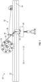
- a hose or cable management system 30 includes a reel 32 mounted to the beam 22 for storing and dispensing the example hose 28.
- the example reel 32 is mounted such that the axis of rotation 33 (see figure 2 ) of the reel 32 is transverse to the beam 22.
- the axis of rotation of the reel 32 can be substantially perpendicular ( ⁇ 10 degrees) to the beam 22.
- the reel 32 may be fixed to a structure other than the beam 22.
- the reel 32 may be fixed against lateral movement in the directions D1 and D2.
- a trough 34 is mounted to the beam 22 for supporting the hose 28 as the trolley 24 moves along the beam 22.
- the trough 34 can extend substantially the whole length of the beam 22.
- the reel 32 is fixed against movement along the length of the beam 22, but the trolley 24 is movable along the length of the beam 22.
- the reel 32 is rotatable to allow for coiling and uncoiling of the hose 28 such that the hose 28 can extend with the trolley 24 as the trolley 24 is moved away from the reel 32 along the beam 22 but also stow the hose 28 as the hose 28 is moved nearer the reel 32.
- the reel 32 allows the hose to extend to desired positions of the trolley 24 while also stowing unnecessary hose to prevent interference, entanglement, etc.
- the management system 30 includes a guide post 36 including a perch 38 extending in a direction transverse to the beam 22 for guiding the hose 28 into the trough 34.
- the example trough 34 prevents entanglement or interreference of the hose 28 with other components of the system by allowing the hose 28 to lay within it.
- Figure 2 illustrates the example guide post 36, including a post 40 mounted to the beam 22 and a perch 38 extending from the post 40.
- the example perch 38 is above, and transverse to, the trough 34.
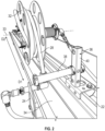
- the reel 32 may be substantially centrally located relative to the beam 22, such that the trolley 24 can move along the beam 22 in a first direction D1 away from the reel 32, as shown in Figure 3 , and in a second direction D2 away from the reel 32 opposite the direction D1, as shown in Figure 4 , with the hose 28 remaining connected and moving with the trolley 24.
- the hose 28 is supported within the trough 34 as the trolley 24 extends in either direction D1, D2.
- the reel 32 may not be centrally located relative to the beam 22 but still able to spin to allow the trolley 24 to move in the D1 and D2 directions.
- the reel 32 rotates in the clockwise direction when the hose is extended away from the reel 32, but rotates in the counterclockwise direction when the hose 28 is retracted back toward the reel 32.
- the trough 34 is V-shaped in cross section when looking in the lengthwise direction (see also Figure 8 ), such that the hose 28 may rest within the inside of the V.
- the trough 34 includes ultra high molecular weight polyethylene or another low friction material to allow the hose 28 to slide within the trough 34.
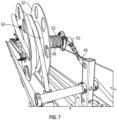
- Figure 7 illustrates the attachment of the cable 46 to the reel 32.
- the reel 32 includes a cylinder 48 extending from, and rotating with, the barrel 50, and the cable 46 is attached to and configured to coil and uncoil around the cylinder 48 as the reel 32 rotates about its rotational axis.
- the cylinder 48 may include a helical groove 52 for receiving the coiling cable 46 in some examples.
- the hose 28 coils around the barrel 50 in the example shown.
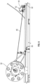
- the example counterbalance 44 allows the hose 28 to be stowed and retracted when desired but also allows the trolley 24 to remain in place when at an extended position along the beam 22. That is, the trolley 24 does not have resistance or pullback from the cable 46.
- the example reel 32 includes one or more ports for hose connection, such that the reel 32 provides part of the fluid path when hoses 28 are utilized.
- one or more rotary unions 53 may be fluidly connected with the hose 28 at the reel 32 and/or the trolley 24 to provide fluid to a rotating component.
- one or more slip rings may be utilized for rotational connection.
- the trolley 24 may include a spring-loaded pad 54 biased to press against a surface of the beam 22.
- the pad 54 may provide friction so as to maintain the trolley 24 in a desired position when extended away from the reel 32.
- the pad 54 is a cylindrical pad.
- the pad 54 includes ultra high molecular weight polyethylene.
- the pad 54 is biased against the upper inner surface 55 of the beam 22, as shown.
- the beam 22 provides an enclosed track 56, providing an internal rolling surface in the beam 22.
- the trolley 24 includes one or more wheels 58 for rolling along the track 56, internal to the beam 22 in the illustrative example.
- the example beam 22 may provide an opening 60 near its bottom end and extending the length of the beam 22 to allow a portion of the trolley 24 to project therethrough below the track 56.
- the beam 22 may include one or more flanges or hooks 62 opposite the surface 55 for suspending the beam 22 from a support in some examples.
- Other beam types and shapes may benefit from this disclosure.
- FIG. 9 illustrates another example crane system 120, substantially similar to the crane system 20, except that a cable 128, such as an electrical or ethernet cable in some examples, is utilized. It should be understood that like reference numerals identify corresponding or similar elements throughout the several drawings.
- the systems and methods described herein prevent cable and hose entanglement, damage, or dislodging.
- the systems and methods further prevent interference with movement of the crane's components.
- the systems and methods provide for offers effortless movement without pullback on the trolley.
- An example crane system may be said to include a beam, a trolley movable along the beam, and a hoist supported by the trolley.
- a cable or a hose connected with at least one of the hoist, the trolley, or a load supported by the hoist; and a management system for the cable or hose.
- the management system includes a reel mounted in a fixed position and receiving the cable or hose, and a trough mounted to the beam for supporting the cable or hose as the trolley moves along the beam.
- An example method in accordance with one or more of the disclosed systems herein may be said to include providing a trolley movable along a beam and a hoist supported by the trolley, mounting a reel in a position fixed against lateral movement, and providing a hose or cable on the reel and connected with at least one of the hoist, the trolley, or a load supported by the hoist.
- the method may include attaching a trough to the beam for receiving the hose or cable, and attaching a load balancer cable to the reel.
- the step of attaching the load balancer cable to the reel includes attaching the load balancer cable to a cylinder extending from a barrel of the reel.
- the step of mounting the reel includes mounting the reel to the beam.
- the method includes positioning a guide post including a perch to direct the hose or cable into the trough. In some examples, positioning the guide post step includes mounting the guide post to the beam. In some examples, the method includes mounting a guide post to the beam, the guide post including a perch to direct the hose or cable into the trough.
Landscapes
- Engineering & Computer Science (AREA)
- Mechanical Engineering (AREA)
- Storing, Repeated Paying-Out, And Re-Storing Of Elongated Articles (AREA)
- Electric Cable Arrangement Between Relatively Moving Parts (AREA)
- Load-Engaging Elements For Cranes (AREA)
Applications Claiming Priority (2)
| Application Number | Priority Date | Filing Date | Title |
|---|---|---|---|
| US202363522326P | 2023-06-21 | 2023-06-21 | |
| US18/217,124 US20240425329A1 (en) | 2023-06-21 | 2023-06-30 | Crane cable and hose management |
Publications (1)
| Publication Number | Publication Date |
|---|---|
| EP4480883A1 true EP4480883A1 (de) | 2024-12-25 |
Family
ID=87553664
Family Applications (1)
| Application Number | Title | Priority Date | Filing Date |
|---|---|---|---|
| EP23188790.2A Pending EP4480883A1 (de) | 2023-06-21 | 2023-07-31 | Krankabel- und schlauchverwaltung |
Country Status (4)
| Country | Link |
|---|---|
| US (1) | US20240425329A1 (de) |
| EP (1) | EP4480883A1 (de) |
| CA (1) | CA3207514A1 (de) |
| MX (1) | MX2023010678A (de) |
Citations (6)
| Publication number | Priority date | Publication date | Assignee | Title |
|---|---|---|---|---|
| US3833774A (en) * | 1972-09-19 | 1974-09-03 | Dresser Ind | Cable support for overhead crane trolleys |
| DE2347511A1 (de) * | 1973-09-21 | 1975-04-03 | Eaton Gmbh | Vorrichtung zur zufuehrung von antriebsenergie oder steuermedien zu begrenzt verfahrbaren arbeitsmaschinen |
| AU579667B2 (en) * | 1984-10-16 | 1988-12-01 | Mission Appliances Pty. Ltd. | Bed lift positioner |
| CN100436300C (zh) * | 2004-03-31 | 2008-11-26 | 佩斯科股份有限公司 | 货物集装箱装卸门式起重机的钢索缠绕支撑系统和方法 |
| US20130118840A1 (en) * | 2010-07-05 | 2013-05-16 | Kone Corporation | Compensation device and elevator |
| DE102018122663A1 (de) * | 2018-09-17 | 2020-03-19 | Stemmann-Technik Gmbh | Leitungszuführungsanordnung |
-
2023
- 2023-06-30 US US18/217,124 patent/US20240425329A1/en active Pending
- 2023-07-24 CA CA3207514A patent/CA3207514A1/en active Pending
- 2023-07-31 EP EP23188790.2A patent/EP4480883A1/de active Pending
- 2023-09-11 MX MX2023010678A patent/MX2023010678A/es unknown
Patent Citations (6)
| Publication number | Priority date | Publication date | Assignee | Title |
|---|---|---|---|---|
| US3833774A (en) * | 1972-09-19 | 1974-09-03 | Dresser Ind | Cable support for overhead crane trolleys |
| DE2347511A1 (de) * | 1973-09-21 | 1975-04-03 | Eaton Gmbh | Vorrichtung zur zufuehrung von antriebsenergie oder steuermedien zu begrenzt verfahrbaren arbeitsmaschinen |
| AU579667B2 (en) * | 1984-10-16 | 1988-12-01 | Mission Appliances Pty. Ltd. | Bed lift positioner |
| CN100436300C (zh) * | 2004-03-31 | 2008-11-26 | 佩斯科股份有限公司 | 货物集装箱装卸门式起重机的钢索缠绕支撑系统和方法 |
| US20130118840A1 (en) * | 2010-07-05 | 2013-05-16 | Kone Corporation | Compensation device and elevator |
| DE102018122663A1 (de) * | 2018-09-17 | 2020-03-19 | Stemmann-Technik Gmbh | Leitungszuführungsanordnung |
Also Published As
| Publication number | Publication date |
|---|---|
| MX2023010678A (es) | 2025-01-09 |
| US20240425329A1 (en) | 2024-12-26 |
| CA3207514A1 (en) | 2025-03-17 |
Similar Documents
| Publication | Publication Date | Title |
|---|---|---|
| US11767192B2 (en) | System and method for handling reel of pipe | |
| US9021644B2 (en) | Method for replacing sloped cables, and temporary hanger for replacing sloped cables | |
| EP3210650B1 (de) | Seilführung | |
| US7104492B1 (en) | Cable winder guide | |
| EP3183201B1 (de) | Windenanordnung und verfahren zur verwendung | |
| US20120048152A1 (en) | Winch and autonomous mobile apparatus including the same | |
| US20140138340A1 (en) | Overhead Hoist | |
| US4375936A (en) | Stacker crane for movement of coils | |
| US11951339B2 (en) | Fall protection system | |
| KR20220166686A (ko) | 모바일 리프터 | |
| US11613443B2 (en) | Mobile cradle frame for pipe reel | |
| EP4480883A1 (de) | Krankabel- und schlauchverwaltung | |
| US11643297B1 (en) | Reel take-up machine | |
| KR101950669B1 (ko) | 원통형 부재 운반용 케이블 로봇 | |
| CN113614019B (zh) | 绞车的绳引导装置 | |
| US4010852A (en) | Sheaving arrangement | |
| US10654691B2 (en) | Overhead crane with remotely located winch | |
| US5875991A (en) | Device for winding up or unwinding elongated flexible articles | |
| CN219408917U (zh) | 一种混凝土管道安装装置 | |
| CN118145500B (zh) | 一种吊具电缆收放装置 | |
| US20060045653A1 (en) | Pick-up and lay-down system and method | |
| CN223547616U (zh) | 一种垂直与水平运输设备快速放线的装置 | |
| KR102847276B1 (ko) | 센서 부품 손상 방지 구조를 갖는 붐 어셈블리 | |
| CN117410887B (zh) | 一种电缆敷设系统、速度控制方法及使用方法 | |
| US12319535B1 (en) | Reel take-up machine |
Legal Events
| Date | Code | Title | Description |
|---|---|---|---|
| PUAI | Public reference made under article 153(3) epc to a published international application that has entered the european phase |
Free format text: ORIGINAL CODE: 0009012 |
|
| STAA | Information on the status of an ep patent application or granted ep patent |
Free format text: STATUS: THE APPLICATION HAS BEEN PUBLISHED |
|
| AK | Designated contracting states |
Kind code of ref document: A1 Designated state(s): AL AT BE BG CH CY CZ DE DK EE ES FI FR GB GR HR HU IE IS IT LI LT LU LV MC ME MK MT NL NO PL PT RO RS SE SI SK SM TR |
|
| STAA | Information on the status of an ep patent application or granted ep patent |
Free format text: STATUS: REQUEST FOR EXAMINATION WAS MADE |
|
| 17P | Request for examination filed |
Effective date: 20250625 |
|
| STAA | Information on the status of an ep patent application or granted ep patent |
Free format text: STATUS: EXAMINATION IS IN PROGRESS |