EP4480856A1 - Article shelf - Google Patents
Article shelf Download PDFInfo
- Publication number
- EP4480856A1 EP4480856A1 EP23756116.2A EP23756116A EP4480856A1 EP 4480856 A1 EP4480856 A1 EP 4480856A1 EP 23756116 A EP23756116 A EP 23756116A EP 4480856 A1 EP4480856 A1 EP 4480856A1
- Authority
- EP
- European Patent Office
- Prior art keywords
- shutter
- frontage
- shelf part
- article
- shelf
- Prior art date
- Legal status (The legal status is an assumption and is not a legal conclusion. Google has not performed a legal analysis and makes no representation as to the accuracy of the status listed.)
- Pending
Links
Images




Classifications
-
- B—PERFORMING OPERATIONS; TRANSPORTING
- B65—CONVEYING; PACKING; STORING; HANDLING THIN OR FILAMENTARY MATERIAL
- B65G—TRANSPORT OR STORAGE DEVICES, e.g. CONVEYORS FOR LOADING OR TIPPING, SHOP CONVEYOR SYSTEMS OR PNEUMATIC TUBE CONVEYORS
- B65G1/00—Storing articles, individually or in orderly arrangement, in warehouses or magazines
- B65G1/02—Storage devices
-
- B—PERFORMING OPERATIONS; TRANSPORTING
- B65—CONVEYING; PACKING; STORING; HANDLING THIN OR FILAMENTARY MATERIAL
- B65G—TRANSPORT OR STORAGE DEVICES, e.g. CONVEYORS FOR LOADING OR TIPPING, SHOP CONVEYOR SYSTEMS OR PNEUMATIC TUBE CONVEYORS
- B65G1/00—Storing articles, individually or in orderly arrangement, in warehouses or magazines
- B65G1/02—Storage devices
- B65G1/04—Storage devices mechanical
- B65G1/0485—Check-in, check-out devices
-
- E—FIXED CONSTRUCTIONS
- E05—LOCKS; KEYS; WINDOW OR DOOR FITTINGS; SAFES
- E05F—DEVICES FOR MOVING WINGS INTO OPEN OR CLOSED POSITION; CHECKS FOR WINGS; WING FITTINGS NOT OTHERWISE PROVIDED FOR, CONCERNED WITH THE FUNCTIONING OF THE WING
- E05F15/00—Power-operated mechanisms for wings
- E05F15/60—Power-operated mechanisms for wings using electrical actuators
- E05F15/603—Power-operated mechanisms for wings using electrical actuators using rotary electromotors
-
- E—FIXED CONSTRUCTIONS
- E05—LOCKS; KEYS; WINDOW OR DOOR FITTINGS; SAFES
- E05F—DEVICES FOR MOVING WINGS INTO OPEN OR CLOSED POSITION; CHECKS FOR WINGS; WING FITTINGS NOT OTHERWISE PROVIDED FOR, CONCERNED WITH THE FUNCTIONING OF THE WING
- E05F15/00—Power-operated mechanisms for wings
- E05F15/70—Power-operated mechanisms for wings with automatic actuation
-
- E—FIXED CONSTRUCTIONS
- E06—DOORS, WINDOWS, SHUTTERS, OR ROLLER BLINDS IN GENERAL; LADDERS
- E06B—FIXED OR MOVABLE CLOSURES FOR OPENINGS IN BUILDINGS, VEHICLES, FENCES OR LIKE ENCLOSURES IN GENERAL, e.g. DOORS, WINDOWS, BLINDS, GATES
- E06B9/00—Screening or protective devices for wall or similar openings, with or without operating or securing mechanisms; Closures of similar construction
- E06B9/02—Shutters, movable grilles, or other safety closing devices, e.g. against burglary
-
- B—PERFORMING OPERATIONS; TRANSPORTING
- B65—CONVEYING; PACKING; STORING; HANDLING THIN OR FILAMENTARY MATERIAL
- B65G—TRANSPORT OR STORAGE DEVICES, e.g. CONVEYORS FOR LOADING OR TIPPING, SHOP CONVEYOR SYSTEMS OR PNEUMATIC TUBE CONVEYORS
- B65G2207/00—Indexing codes relating to constructional details, configuration and additional features of a handling device, e.g. Conveyors
- B65G2207/40—Safety features of loads, equipment or persons
-
- E—FIXED CONSTRUCTIONS
- E05—LOCKS; KEYS; WINDOW OR DOOR FITTINGS; SAFES
- E05Y—INDEXING SCHEME ASSOCIATED WITH SUBCLASSES E05D AND E05F, RELATING TO CONSTRUCTION ELEMENTS, ELECTRIC CONTROL, POWER SUPPLY, POWER SIGNAL OR TRANSMISSION, USER INTERFACES, MOUNTING OR COUPLING, DETAILS, ACCESSORIES, AUXILIARY OPERATIONS NOT OTHERWISE PROVIDED FOR, APPLICATION THEREOF
- E05Y2400/00—Electronic control; Electrical power; Power supply; Power or signal transmission; User interfaces
- E05Y2400/10—Electronic control
- E05Y2400/32—Position control, detection or monitoring
Definitions
- the present invention relates to an article shelf on which an article is placed.
- the present invention relates to an article shelf that has two frontages to transfer an article, and is equipped with a safety device that closes the other frontage when one frontage is used to transfer the article.
- a conveyance device such as a stacker crane places an article on a shelf, and that an operator performs a predetermined operation (such as a picking operation) on the article placed on the shelf.
- the shelf used for this purpose has a frontage to transfer the article from the conveyance device to the shelf, and a frontage for the operator to perform the operation on the article placed on the shelf. Note that these two frontages are disposed to face each other.
- the shelf described above is equipped with a safety device having a shutter, which closes the frontage on the operator side when transferring the article from the conveyance device to the shelf, and closes the frontage on the conveyance device side when the operator performs the operation on the article on the shelf (see, for example, Patent Citation 1).
- Patent Citation 1 JP-A-H11-165811
- the shutter of the conventional safety device moves from the frontage to be opened to the frontage to be closed along an upper part of the shelf. Therefore, if the shutter stops before reaching the frontage to be closed due to an abnormality or the like, for example, the frontage on the side for the operator to perform the operation, and the frontage on the side for the conveyance device to transfer the article may be both open on lower sides thereof. If the both frontages are open on lower sides thereof, the operator can access the shelf while the conveyance device is transferring the article. Therefore, it is preferred to avoid the situation in which the both frontages are opened on lower sides thereof.
- An article shelf includes a shelf part, two frontages, a shutter, and a drive unit.
- the shelf part places an article at a position apart from a floor surface.
- the two frontages are disposed to face each other in a direction perpendicular to a width direction of the shelf part to access to the shelf part.
- the shutter opens one of the two frontages and closes the other. When moving to switch the frontage to be closed, the shutter passes through a space between the floor surface and the shelf part.
- the shutter when the shutter moves to switch the frontage to be closed, the shutter passes through the space between the floor surface and the shelf part, to move from one frontage to the other frontage. In this way, even if the shutter stops during movement from one frontage to the other frontage, at least one of the two frontages is closed by the shutter on its lower side, and it is possible to prevent two frontages from being simultaneously opened on lower sides thereof.
- the shutter passes through the space between the shelf part and the floor surface, to switch the frontage, if an automated guided vehicle and/or a human or the like exist in the space between the shelf part and the floor surface, switching of the frontage cannot be performed. As a result, without detecting whether or not an automated guided vehicle and/or a human or the like exist in the space between the shelf part and the floor surface using a sensor or the like, it is possible to determine whether or not the frontage can be switched.
- the article shelf may further include a drive unit.
- the drive unit may include a pair of drive members.
- the pair of drive members are disposed with an interval therebetween that is larger than a width of the shelf part, to move the shutter while supporting both end portions of the shutter.
- Each of the drive members may include four rotating members and an endless member.
- the four rotating members are disposed at four corners along a movement path of the shutter.
- the endless member is wrapped around the four rotating members, to support an end of the shutter. In this way, the shutter can be equipped to the article shelf, using a simple structure of the rotating members and the endless member.
- the drive unit may move the shutter by rotating one of the four rotating members of the pair of drive members. In this way, it is possible to drive the shutter by a simple structure of rotating one rotating member.
- the article shelf described above may further include two sensors configured to detect the shutter.
- the two sensors are disposed side by side along the movement path of the shutter.
- the shutter may continue to move if the two sensors both detect the shutter, while it may stop if one of the two sensors does not detect the shutter. In this way, it is possible to appropriately move the shutter by a simple structure in which only the two sensors are disposed.
- the article shelf described above may further include three sensors configured to detect the shutter.
- the three sensors are disposed side by side along the movement path of the shutter. In this way, more advanced movement of the shutter can be realized.
- the shutter may have a length corresponding to the sum of the height of the frontage and the length in a direction perpendicular to the width direction of the shelf part.
- the sensors may be disposed in a vicinity of one of the two frontages. Further, it may be determined whether or not to stop the shutter if one of the two sensors does not detect the shutter, based on a movement direction of the shutter. In this way, by changing functions of the two sensors based on the movement direction of the shutter, it is possible to appropriately move the shutter with a small number of sensors.
- the shutter may have a length corresponding to the sum of the height of the frontage and the length in the direction perpendicular to the width direction of the shelf part.
- three sensors may be disposed in a vicinity of one of the frontages. Further, if the shutter becomes undetected by one of the three sensors, it may be determined whether or not to decrease the moving speed of the shutter or to stop the shutter, based on the movement direction of the shutter. In this way, by switching functions of the three sensors based on the movement direction of the shutter, more advanced movement of the shutter can be realized.
- the state of the shutter may be recognized by circularly moving the shutter to cause the sensors to detect the shutter. In this way, even in the state where the state of the shutter cannot be recognized when the device is recovered from an abnormal state or when the device starts, the state of the shutter can be recognized by the operation described above.
- Fig. 1 is a plan view of the automated warehouse 1.
- Fig. 2 is a diagram of a safety device 4 viewed from an extending direction of a rack 3.
- Fig. 3 is a diagram of the safety device 4 viewed from a first frontage 33a side.
- the left and right direction in Fig. 1 is defined as an X direction
- the up and down direction in Fig. 1 is defined as a Y direction
- the direction perpendicular to the paper of Fig. 1 i.e., a height direction
- Z direction the direction perpendicular to the paper of Fig. 1
- the automated warehouse 1 is installed at a logistics base such as a factory or a storage facility, for example, and is a facility in which storing, loading, and unloading of articles A can be performed.
- the articles A that can be stored, loaded, and unloaded in the automated warehouse 1 include, for example, a package itself, packages placed on a pallet, and the like.
- the automated warehouse 1 includes the rack 3 (an example of the article shelf) and a conveyance device 5.
- the rack 3 is a facility that is configured to store the articles A.
- the rack 3 includes a plurality of shelf parts 31 on which the articles A are placed.
- the plurality of shelf parts 31 are arranged along the X direction.
- the shelf part 31 is fixed to a first frame FL1 extending in the Z direction, at a position apart upward from a floor surface F by a predetermined distance, and can place the article A at the position apart from the floor surface F.
- the rack 3 may further include a plurality of shelves that is configured to place the articles A, arranged in the Z direction (the height direction).
- the articles A to be placed on the shelf part 31 have various sizes.
- the length of the article A may be longer than the length of the shelf part 31 in the Y direction or may be shorter than the same.
- the rack 3 has two frontages, i.e., the first frontage 33a and a second frontage 33b, to access to each shelf part 31.
- the first frontage 33a is disposed on a side of the shelf part 31 facing the conveyance device 5.
- the first frontage 33a is used when transferring the article A from the conveyance device 5 to the shelf part 31, or from the shelf part 31 to the conveyance device 5.
- the second frontage 33b is disposed to face the first frontage 33a via the shelf part 31 in the Y direction. In other words, the second frontage 33b is disposed on a side of the shelf part 31 opposite to the side facing the conveyance device 5.
- the second frontage 33b is used when an operator W makes access to the shelf part 31. Specifically, the operator W can enter the shelf part 31 from an external workbench 35 through the second frontage 33b. In addition, the operator W can move from the shelf part 31 to the external workbench 35 through the second frontage 33b. In this way, for example, the operator W can enter the shelf part 31 and perform a predetermined operation on the article A placed on the shelf part 31. For instance, it is possible to move the article A from the shelf part 31 to the outside. In addition, it is possible to place the article A onto the shelf part 31 from the outside.
- the operator W existing outside the rack 3 can perform picking (so-called "back face picking") of the article A placed on the shelf part 31, using the second frontage 33b.
- the second frontage 33b may have a size such that the operator W can pass through, or may have a size such that a vehicle such as a forklift can pass through. In the latter case, not only the operator W but also the vehicle can enter the shelf part 31.
- the rack 3 is equipped with the safety device 4 that is configured to open the frontage that is currently in use while closing the frontage that is currently not in use, between the first frontage 33a and the second frontage 33b.
- the safety device 4 A specific structure of the safety device 4 will be described later in detail.
- the conveyance device 5 is a device that conveys the article A among the plurality of shelf parts 31, a storage station, and/or a retrieval station. Specifically, the conveyance device 5 moves along a guide rail 51 laid along the X direction (i.e., the arrangement direction of the plurality of shelf parts 31), to convey the article A.
- the conveyance device 5 is a stacker crane, for example.
- the conveyance device 5 includes a transfer device 53.
- the transfer device 53 is a device that is configured to transfer the article A between the conveyance device 5 and the shelf part 31, the storage station, or the retrieval station.
- the transfer device 53 holds the article A, extends from the transfer device 53 to the shelf part 31 through the first frontage 33a in the Y direction, and then releases holding of the article A, so that the article A can be transferred from the conveyance device 5 to the shelf part 31.
- the transfer device 53 extends from the transfer device 53 to the shelf part 31 through the first frontage 33a, holds the article A placed on the shelf part 31, and then retracts from the shelf part 31 to the transfer device 53 while keeping holding the article A, so that the article A can be transferred from the shelf part 31 to the conveyance device 5.
- this transfer device 53 for example, there is a device having a slide fork that can extend and retract in the Y direction and has an upper part on which the article A can be placed, or a device having an arm that can extend and retract in the Y direction to which a member for holding the article A is provided.
- FIG. 1 illustrates an example of the automated warehouse 1, in which one rack 3 and one conveyance device 5 are arranged side by side in the Y direction, but the structure of the automated warehouse 1 is not limited to this.
- a plurality of the racks 3 and a plurality of the conveyance devices 5 may be alternately arranged side by side in the Y direction.
- the safety device 4 includes a shutter 41 and a drive unit 43.
- the shutter 41 opens one of the first frontage 33a and the second frontage 33b, to access to the shelf part 31, while it closes the other frontage, to inhibit access to the shelf part
- the shutter 41 includes a shutter member 41a and shutter support members 41b.
- the shutter member 41a is a flat member having a predetermined width and length.
- the width of the shutter member 41a is set larger than the width (X direction length) of a placing part of the article A on the shelf part 31.
- the length of the shutter member 41a (the length in the Y direction and the Z direction) is set to a length corresponding to the sum of the length (i.e., the height) of the frontage (the first frontage 33a or the second frontage 33b) in the Z direction and the length of the shelf part 31 in the Y direction (the direction perpendicular to the width direction). Having this size, the shutter member 41a can cover the entire frontage and the entire lower part of the shelf part 31 at the same time, when its one end in the length direction reaches the uppermost part of the frontage.
- the length of the shutter member 41a is not required to have the above size as long as security can be assured in the automated warehouse 1. For instance, if the shelf part 31 is long in the Y direction, the shutter member 41a is not always required to have the length that covers the entire frontage and the entire lower part of the shelf part 31.
- the shutter support member 41b is a rod-like member that is configured to support the shutter member 41a.
- a plurality of the shutter support members 41b are arranged side by side in the length direction of the shutter member 41a, and are fixed to the shutter member 41a except for their both end parts.
- the both end parts of the shutter support members 41b are each fixed to an endless member of a drive member. As the both end parts of the shutter support members 41b are each fixed to the endless member, the shutter 41 (the shutter member 41a) can move along with the movement of the endless members of the drive member.
- the drive unit 43 drives the shutter 41.
- the drive unit 43 includes a pair of drive members 43a and 43b.
- the pair of drive members 43a and 43b are disposed with a space therebetween, which is larger than the width of the placing part of the article A on the shelf part 31.
- the drive member 43a is disposed on the left side, while the drive member 43b is disposed on the right side.
- the pair of drive members 43a and 43b moves the shutter 41, while supporting the both end parts of the shutter 41 (the both end parts of the shutter support members 41b) in the width direction.
- the pair of drive members 43a and 43b have four rotating members 431a and 431b and endless members 433a and 433b, respectively.
- the four rotating members 431a and 431b are disposed at four corners along a movement path of the shutter 41.
- the rotating members 431a and 431b are sprockets, pulleys, or the like, for example.
- two rotating members 431a among the four rotating members 431a are disposed in a rotatable manner about an X axis, in the lower part of the shelf part 31 at the end parts in the Y direction on the left side viewed from the first frontage 33a.
- the other two rotating members 431a are disposed in a rotatable manner about the X axis, at the end parts of a second frame FL2 in the Y direction on the left side viewed from the first frontage 33a.
- the second frame FL2 is fixed to the first frame FL1 at the upper part of the shelf part 31 of the rack 3.
- two rotating members 431b among four rotating members 431b are disposed in a rotatable manner about the X axis, at the lower part of the shelf part 31 at the end parts in the Y direction on the right side viewed from the first frontage 33a.
- the other two rotating members 431b are disposed in a rotatable manner about the X axis, at the end parts of the second frame FL2 in the Y direction on the right side viewed from the first frontage 33a.
- the endless member 433a is wrapped around the four rotating members 431a disposed on the left side viewed from the first frontage 33a, and moves when the four rotating members 431a rotate about the X axis. In addition, the endless member 433a fixes the end parts of the shutter support members 41b on the left side, to support the shutter 41 on the left side.
- the endless member 433b is wrapped around the four rotating members 431b disposed on the right side viewed from the first frontage 33a, and moves when the four rotating members 431b rotate about the X axis. In addition, the endless member 433b fixes the end parts of the shutter support members 41b on the right side, to support the shutter 41 on the right side.
- the endless members 433a and 433b are chains, for example.
- the endless members 433a and 433b are endless belt members such as timing belts, for example.
- the drive unit 43 further includes a drive supply unit 435.
- the drive supply unit 435 supplies driving force to rotate one of the four rotating members 431a and one of the rotating members 431b facing the one of the rotating members 431a in the X direction.
- the drive supply unit 435 includes a motor and a drive conversion mechanism that converts rotation of the motor into rotation of the rotating members about the X axis, for example.
- the drive unit 43 can move the shutter 41 supported by the endless members 433a and 433b, with a simple structure in which the drive supply unit 435 causes one of the four rotating members to rotate.
- the safety device 4 further includes a first sensor 45a and a second sensor 45b.
- the first sensor 45a and the second sensor 45b are each a sensor that is configured to detect the shutter 41.
- the first sensor 45a and the second sensor 45b are each a photoelectric sensor that detects the shutter 41 when the shutter 41 blocks the light, for example.
- the first sensor 45a and the second sensor 45b are disposed side by side along the movement path of the shutter 41 in the space SP between the shelf part 31 and the floor surface F, in a vicinity of the first frontage 33a in the lower part of the shelf part 31. Specifically, the first sensor 45a is disposed on the side close to the first frontage 33a, while the second sensor 45b is disposed on the side apart from the first frontage 33a.
- the movement direction and the position of the shutter 41 can be detected based on whether or not the shutter 41 is detected by which one of the two sensors.
- the method of detecting the movement direction and the position of the shutter 41 using the two sensors will be described later.
- the automated warehouse 1 further includes a controller 7.
- the controller 7 is a computer system including a CPU, a storage device (such as a RAM and a ROM), and various interfaces, to control individual components of the automated warehouse 1.
- the control of individual components of the automated warehouse 1 may be realized by a program, which is stored in the storage device of the controller 7 and can be executed by the controller 7.
- a part or the whole of the control of the individual components may be realized by hardware constituting the controller 7.
- Fig. 4 a control structure of the automated warehouse 1 by the controller 7 is described.
- Fig. 4 is a diagram illustrating the control structure of the automated warehouse 1.
- the controller 7 controls the travel of the conveyance device 5 and the transfer of the article A by the transfer device 53, based on a host controller 8.
- the host controller 8 is a computer system that administrates the articles A in the automated warehouse 1.
- the controller 7 controls the drive supply unit 435 to control movement of the shutter 41, based on a command from the host controller 8 and/or an operation unit 9. For instance, if the host controller 8 issues a command to transfer the article A from the conveyance device 5 to the shelf part 31 or in the opposite direction, the controller 7 outputs a signal to the drive supply unit 435, to move the shutter 41 in the direction of opening the first frontage 33a while closing the second frontage 33b.
- the controller 7 determines that the operator W will do an operation in the shelf part 31, and outputs a signal to the drive supply unit 43 5, to move the shutter 41 in the direction of opening the second frontage 33b while closing the first frontage 33a.
- the controller 7 recognizes a state of the shutter 41 based on detection results of the shutter 41 by the first sensor 45a and the second sensor 45b, and output to the drive supply unit 435 a signal to control movement of the shutter 41, based on the recognized state of the shutter 41.
- the transfer operation of the article A between the conveyance device 5 and the shelf part 31 is described.
- the controller 7 moves the shutter 41 to close the second frontage 33b and to open the first frontage 33a.
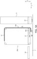
- Fig. 5A is a diagram illustrating a state where the first frontage 33a is closed by the shutter 41.
- the first sensor 45a on the side close to the first frontage 33a detects the shutter 41, while the second sensor 45b on the side close to the second frontage 33b does not detect the shutter 41.
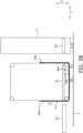
- Fig. 5B is a diagram illustrating a state where the shutter 41 is on the move to the second frontage 33b.
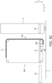
- Fig. 5C is a diagram illustrating the state where the second frontage 33b is closed by the shutter 41.
- the conveyance device 5 can extend the transfer device 53 to the shelf part 31, to transfer the article A from or to the shelf part 31.
- the operator W cannot enter the shelf part 31 because the second frontage 33b is closed.
- the safety device 4 inhibit the operator W from making access to the shelf part 31 while the conveyance device 5 makes access to the shelf part 31, to ensure safety.
- Fig. 6A is a diagram illustrating a state where the second frontage 33b is closed by the shutter 41.
- both the first sensor 45a and the second sensor 45b detect the shutter 41.
- the controller 7 determines that the shutter 41 is on the move to the first frontage 33a, and continues the movement of the shutter 41 to the first frontage 33a.
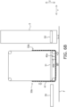
- Fig. 6B is a diagram illustrating a state where the shutter 41 is on the move to the first frontage 33a.
- Fig. 6C is a diagram illustrating a state where the first frontage 33a is closed by the shutter 41.
- the operator W can pass through the second frontage 33b to enter the shelf part 31, to perform a predetermined operation on the article A.
- the conveyance device 5 cannot extend the transfer device 53 to the shelf part 31 because the first frontage 33a is closed.
- the safety device 4 inhibit the transfer device 53 of the conveyance device 5 from making access to the shelf part 31 while the operator W makes access to the shelf part 31, to ensure safety.
- the shutter 41 when moving the shutter 41 to switch the frontage to be closed, the shutter 41 passes through the space SP between the floor surface F and the shelf part 31, to move from one of the frontages to the other frontage.
- the lower sides of the first frontage 33a and the second frontage 33b are closed by the shutter 41 as illustrated in Figs. 5B and 6B .
- the lower sides of the two frontages are not simultaneously opened.
- the conveyance device 5 While the conveyance device 5 is operating, the operator W cannot either make access to the shelf part 31 or go through the shelf part 31 to move to the conveyance device 5 side. In addition, while the operator W is performing a predetermined operation on the shelf part 31, or when the operator W is left in the shelf part 31, the transfer device 53 cannot make access to the shelf part 31.
- the controller 7 determines that the shutter 41 is not in the normal position, and issues an abnormality alarm.
- the state of the shutter 41 (the position or the like of the shutter 41) cannot be recognized from the detection states of the shutter 41 by the first sensor 45a and the second sensor 45b.
- the controller 7 cannot recognize which direction the shutter 41 was moving in, or which position the shutter 41 is stopped at.
- the controller 7 cannot recognize which direction the shutter 41 was moving in, or the position thereof as well.
- the controller 7 allows the shutter 41 to move circularly along the first frontage 33a, the space SP between the shelf part 31 and the floor surface F, the second frontage 33b, and the upper part of the shelf part 31, to cause or not cause the first sensor 45a and the second sensor 45b to detect the shutter 41.
- the shutter 41 is moved in the direction starting from the lower part of the second frontage 33b where the operator W exists, and then closing the second frontage 33b.
- the controller 7 can recognize the state of the shutter 41. For instance, when circularly moving the shutter 41, suppose that both the first sensor 45a and the second sensor 45b detect the shutter 41, and that afterward the state occurs in which the second sensor 45b still detects the shutter 41 while the first sensor 45a does not detect the shutter 41. Then, the controller 7 can recognize that the shutter 41 is in the state (at the position) to close the second frontage 33b.
- the startup operation described above may be finished without whole circular movement of the shutter 41, if one of the first sensor 45a and the second sensor 45b detects the shutter 41 after both sensors detect the shutter 41.
- An article shelf (e.g., the rack 3) includes a shelf part (e.g., the shelf part 31), two frontages (e.g., the first frontage 33a and the second frontage 33b), a shutter (e.g., the shutter 41), a drive unit (e.g., the drive unit 43), and a controller (e.g., the controller 7).
- the shelf part is configured to place an article (e.g., the article A) at a position apart from a floor surface (e.g., the floor surface F).
- the two frontages are disposed to face each other in a direction (e.g., the Y direction) perpendicular to a width direction of the shelf part (e.g., the X direction), to access to the shelf part.
- the shutter opens one of the two frontages and closes the other.
- the drive unit drives the shutter.
- the controller controls the drive unit to control movement of the shutter.
- the controller causes the shutter to pass through a space between the floor surface and the shelf part (e.g., the space SP).
- the shutter when causing the shutter to move to switch the frontage to be closed, the shutter passes through the space between the floor surface and the shelf part, to move from one of the frontages to the other frontage. In this way, even if the shutter stops on the move from one frontage to the other frontage, at least one of the two frontages is closed on its lower side by the shutter, and hence it is possible to prevent two frontages from being simultaneously opened on lower sides thereof.
- the controller 7 determines to decrease the moving speed of the shutter 41 or to stop the shutter 41, based on the movement direction of the shutter 41.
- the controller 7 can perform the following control. If the shutter 41 is detected by all the first to third sensors 45a to 45c, and afterward the shutter 41 is undetected by only the first sensor 45a, the controller 7 decreases the moving speed of the shutter 41. After that, if the shutter 41 is undetected by the first sensor 45a and the third sensor 45c, the controller 7 stops the shutter 41. In this case, as the second sensor 45b remains detecting the shutter, it is understood that the end of the shutter is stopped between the third sensor 45c and the second sensor 45b.
- the controller 7 can perform the following control. If the shutter 41 is detected by all the first to third sensors 45a to 45c, and afterward the shutter 41 is undetected by only the second sensor 45b, the controller 7 decreases the moving speed of the shutter 41. After that, if the shutter 41 is undetected by the second sensor 45b and the third sensor 45c, the controller 7 stops the shutter 41. In this case, as the first sensor 45a remains detecting the shutter, it is understood that the end of the shutter is stopped between the third sensor 45c and the first sensor 45a.
- the safety device 4 described above can be provided not only to the rack 3 but also to a general shelf of the article A having two frontages.
- the shelf part 31 may be able to move up and down in the Z direction.
- the shelf part 31 that can move up and down may be, for example, a power slider, an elevating lift, or the like.
- the operator W can make access from the floor surface F to the shelf part 31.
- an automatic guided vehicle (AGV) that travels on the floor surface F can make access to the shelf part 31.
- the space SP between the shelf part 31 and the floor surface F may allow an automatic guided vehicle to enter.
- the automatic guided vehicle is equipped with a shelf of the article A that can move in the up and down direction, and the automatic guided vehicle enters the space SP and uses the shelf to lift the article A placed on shelf part 31, so that the article A can be transferred from the shelf part 31 to the shelf.
- the shutter 41 passes through the space SP between the shelf part 31 and the floor surface F, to switch between the first frontage 33a and the second frontage 33b. Therefore, if there is an automatic guided vehicle and/or a human or the like in the space SP between the shelf part 31 and the floor surface F, the switching of the frontage cannot be performed. As a result, it is possible to determine whether or not the frontage can be switched, without detecting whether or not an automated guided vehicle and/or a human or the like exist in the space SP between the shelf part 31 and the floor surface F.
- the length of the shutter 41 may be any length as long as it is more than or equal to a length corresponding to the sum of the height of one frontage and the length of the shelf part 31 in the Y direction.
- the length of the shutter 41 may be changeable in accordance with the length of the shelf part 31 in the Y direction.
- the drive members 43a and 43b may further include a rotating members that is configured to adjust tensions of the endless members 433a and 433b, respectively.
- This rotating member pushes or pulls the endless member 433a, 433b wrapped around the four rotating members 431a, 431b, to adjust the tension.
- the four rotating members 431a, 431b can move in any direction, and that the tension of the endless member 433a, 433b is adjustable by adjusting the distance between the rotating members 431a, 431b.
- the method of realizing the movement of the shutter 41 is not limited to the control by the controller 7 as described above.
- the movement of the shutter 41 may be realized by an operation of a button or the like.
- the present invention can be widely applied to article shelves on which an article is placed.
Landscapes
- Engineering & Computer Science (AREA)
- Mechanical Engineering (AREA)
- Structural Engineering (AREA)
- Architecture (AREA)
- Civil Engineering (AREA)
- Warehouses Or Storage Devices (AREA)
Abstract
Description
- The present invention relates to an article shelf on which an article is placed. In particular, the present invention relates to an article shelf that has two frontages to transfer an article, and is equipped with a safety device that closes the other frontage when one frontage is used to transfer the article.
- Conventionally, it is known that a conveyance device such as a stacker crane places an article on a shelf, and that an operator performs a predetermined operation (such as a picking operation) on the article placed on the shelf. The shelf used for this purpose has a frontage to transfer the article from the conveyance device to the shelf, and a frontage for the operator to perform the operation on the article placed on the shelf. Note that these two frontages are disposed to face each other.
- In addition, the shelf described above is equipped with a safety device having a shutter, which closes the frontage on the operator side when transferring the article from the conveyance device to the shelf, and closes the frontage on the conveyance device side when the operator performs the operation on the article on the shelf (see, for example, Patent Citation 1).
- Patent Citation 1:
JP-A-H11-165811 - When switching the frontage to be closed, the shutter of the conventional safety device moves from the frontage to be opened to the frontage to be closed along an upper part of the shelf. Therefore, if the shutter stops before reaching the frontage to be closed due to an abnormality or the like, for example, the frontage on the side for the operator to perform the operation, and the frontage on the side for the conveyance device to transfer the article may be both open on lower sides thereof. If the both frontages are open on lower sides thereof, the operator can access the shelf while the conveyance device is transferring the article. Therefore, it is preferred to avoid the situation in which the both frontages are opened on lower sides thereof.
- It is an object of the present invention to prevent two frontages from being simultaneously opened on lower sides thereof, in an article shelf having two frontages facing each other.
- Hereinafter, a plurality of embodiments are described as means for solving the problem. These embodiments can be arbitrarily combined as necessary.
- An article shelf according to an aspect of the present invention includes a shelf part, two frontages, a shutter, and a drive unit. The shelf part places an article at a position apart from a floor surface. The two frontages are disposed to face each other in a direction perpendicular to a width direction of the shelf part to access to the shelf part. The shutter opens one of the two frontages and closes the other. When moving to switch the frontage to be closed, the shutter passes through a space between the floor surface and the shelf part.
- In the article shelf described above, when the shutter moves to switch the frontage to be closed, the shutter passes through the space between the floor surface and the shelf part, to move from one frontage to the other frontage. In this way, even if the shutter stops during movement from one frontage to the other frontage, at least one of the two frontages is closed by the shutter on its lower side, and it is possible to prevent two frontages from being simultaneously opened on lower sides thereof. In addition, as the shutter passes through the space between the shelf part and the floor surface, to switch the frontage, if an automated guided vehicle and/or a human or the like exist in the space between the shelf part and the floor surface, switching of the frontage cannot be performed. As a result, without detecting whether or not an automated guided vehicle and/or a human or the like exist in the space between the shelf part and the floor surface using a sensor or the like, it is possible to determine whether or not the frontage can be switched.
- The article shelf may further include a drive unit. The drive unit may include a pair of drive members. The pair of drive members are disposed with an interval therebetween that is larger than a width of the shelf part, to move the shutter while supporting both end portions of the shutter. Each of the drive members may include four rotating members and an endless member. The four rotating members are disposed at four corners along a movement path of the shutter. The endless member is wrapped around the four rotating members, to support an end of the shutter. In this way, the shutter can be equipped to the article shelf, using a simple structure of the rotating members and the endless member.
- The drive unit may move the shutter by rotating one of the four rotating members of the pair of drive members. In this way, it is possible to drive the shutter by a simple structure of rotating one rotating member.
- The article shelf described above may further include two sensors configured to detect the shutter. The two sensors are disposed side by side along the movement path of the shutter. In this case, the shutter may continue to move if the two sensors both detect the shutter, while it may stop if one of the two sensors does not detect the shutter. In this way, it is possible to appropriately move the shutter by a simple structure in which only the two sensors are disposed.
- The article shelf described above may further include three sensors configured to detect the shutter. The three sensors are disposed side by side along the movement path of the shutter. In this way, more advanced movement of the shutter can be realized.
- The shutter may have a length corresponding to the sum of the height of the frontage and the length in a direction perpendicular to the width direction of the shelf part. In addition, the sensors may be disposed in a vicinity of one of the two frontages. Further, it may be determined whether or not to stop the shutter if one of the two sensors does not detect the shutter, based on a movement direction of the shutter. In this way, by changing functions of the two sensors based on the movement direction of the shutter, it is possible to appropriately move the shutter with a small number of sensors.
- The shutter may have a length corresponding to the sum of the height of the frontage and the length in the direction perpendicular to the width direction of the shelf part. In addition, three sensors may be disposed in a vicinity of one of the frontages. Further, if the shutter becomes undetected by one of the three sensors, it may be determined whether or not to decrease the moving speed of the shutter or to stop the shutter, based on the movement direction of the shutter. In this way, by switching functions of the three sensors based on the movement direction of the shutter, more advanced movement of the shutter can be realized.
- If the state of the shutter cannot be recognized using the sensors, the state of the shutter may be recognized by circularly moving the shutter to cause the sensors to detect the shutter. In this way, even in the state where the state of the shutter cannot be recognized when the device is recovered from an abnormal state or when the device starts, the state of the shutter can be recognized by the operation described above.
- It is possible to prevent two frontages from being simultaneously opened on lower sides thereof.
-
-
Fig. 1 is a plan view of an automated warehouse. -
Fig. 2 is a diagram of a safety device viewed from a rack extending direction. -
Fig. 3 is a diagram of a safety device viewed from a first frontage side. -
Fig. 4 is a diagram illustrating a control structure of the automated warehouse. -
Fig. 5A is a diagram illustrating a state where the first frontage is closed by a shutter. -
Fig. 5B is a diagram illustrating a state where the shutter is on the move to a second frontage. -
Fig. 5C is a diagram illustrating a state where the second frontage is closed by the shutter. -
Fig. 6A is a diagram illustrating a state where the second frontage is closed by the shutter. -
Fig. 6B is a diagram illustrating a state where the shutter is on the move to the first frontage. -
Fig. 6C is a diagram illustrating a state where the first frontage is closed by the shutter. - With reference to
Figs. 1 to 3 , anautomated warehouse 1 including an article shelf according to the present disclosure is described.Fig. 1 is a plan view of theautomated warehouse 1.Fig. 2 is a diagram of asafety device 4 viewed from an extending direction of a rack 3.Fig. 3 is a diagram of thesafety device 4 viewed from afirst frontage 33a side. In the following description, the left and right direction inFig. 1 is defined as an X direction, the up and down direction inFig. 1 is defined as a Y direction, and the direction perpendicular to the paper ofFig. 1 (i.e., a height direction) is defined as a Z direction. Theautomated warehouse 1 is installed at a logistics base such as a factory or a storage facility, for example, and is a facility in which storing, loading, and unloading of articles A can be performed. The articles A that can be stored, loaded, and unloaded in theautomated warehouse 1 include, for example, a package itself, packages placed on a pallet, and the like. Theautomated warehouse 1 includes the rack 3 (an example of the article shelf) and aconveyance device 5. - The rack 3 is a facility that is configured to store the articles A. The rack 3 includes a plurality of
shelf parts 31 on which the articles A are placed. The plurality ofshelf parts 31 are arranged along the X direction. Theshelf part 31 is fixed to a first frame FL1 extending in the Z direction, at a position apart upward from a floor surface F by a predetermined distance, and can place the article A at the position apart from the floor surface F. Note that the rack 3 may further include a plurality of shelves that is configured to place the articles A, arranged in the Z direction (the height direction). - Note that the articles A to be placed on the
shelf part 31 have various sizes. For instance, the length of the article A may be longer than the length of theshelf part 31 in the Y direction or may be shorter than the same. - The rack 3 has two frontages, i.e., the
first frontage 33a and asecond frontage 33b, to access to eachshelf part 31. Thefirst frontage 33a is disposed on a side of theshelf part 31 facing theconveyance device 5. Thefirst frontage 33a is used when transferring the article A from theconveyance device 5 to theshelf part 31, or from theshelf part 31 to theconveyance device 5. - The
second frontage 33b is disposed to face thefirst frontage 33a via theshelf part 31 in the Y direction. In other words, thesecond frontage 33b is disposed on a side of theshelf part 31 opposite to the side facing theconveyance device 5. Thesecond frontage 33b is used when an operator W makes access to theshelf part 31. Specifically, the operator W can enter theshelf part 31 from anexternal workbench 35 through thesecond frontage 33b. In addition, the operator W can move from theshelf part 31 to theexternal workbench 35 through thesecond frontage 33b. In this way, for example, the operator W can enter theshelf part 31 and perform a predetermined operation on the article A placed on theshelf part 31. For instance, it is possible to move the article A from theshelf part 31 to the outside. In addition, it is possible to place the article A onto theshelf part 31 from the outside. - In addition, the operator W existing outside the rack 3 can perform picking (so-called "back face picking") of the article A placed on the
shelf part 31, using thesecond frontage 33b. - The
second frontage 33b may have a size such that the operator W can pass through, or may have a size such that a vehicle such as a forklift can pass through. In the latter case, not only the operator W but also the vehicle can enter theshelf part 31. - In addition, the rack 3 is equipped with the
safety device 4 that is configured to open the frontage that is currently in use while closing the frontage that is currently not in use, between thefirst frontage 33a and thesecond frontage 33b. A specific structure of thesafety device 4 will be described later in detail. - The
conveyance device 5 is a device that conveys the article A among the plurality ofshelf parts 31, a storage station, and/or a retrieval station. Specifically, theconveyance device 5 moves along aguide rail 51 laid along the X direction (i.e., the arrangement direction of the plurality of shelf parts 31), to convey the article A. Theconveyance device 5 is a stacker crane, for example. - The
conveyance device 5 includes atransfer device 53. Thetransfer device 53 is a device that is configured to transfer the article A between theconveyance device 5 and theshelf part 31, the storage station, or the retrieval station. Thetransfer device 53 holds the article A, extends from thetransfer device 53 to theshelf part 31 through thefirst frontage 33a in the Y direction, and then releases holding of the article A, so that the article A can be transferred from theconveyance device 5 to theshelf part 31. On the other hand, thetransfer device 53 extends from thetransfer device 53 to theshelf part 31 through thefirst frontage 33a, holds the article A placed on theshelf part 31, and then retracts from theshelf part 31 to thetransfer device 53 while keeping holding the article A, so that the article A can be transferred from theshelf part 31 to theconveyance device 5. As thistransfer device 53, for example, there is a device having a slide fork that can extend and retract in the Y direction and has an upper part on which the article A can be placed, or a device having an arm that can extend and retract in the Y direction to which a member for holding the article A is provided. - Note that
Fig. 1 illustrates an example of theautomated warehouse 1, in which one rack 3 and oneconveyance device 5 are arranged side by side in the Y direction, but the structure of theautomated warehouse 1 is not limited to this. In another example of theautomated warehouse 1, a plurality of the racks 3 and a plurality of theconveyance devices 5 may be alternately arranged side by side in the Y direction. - Hereinafter, with reference to
Figs. 2 and3 , a structure of thesafety device 4 provided to eachshelf part 31 of the rack 3 is described. Thesafety device 4 includes ashutter 41 and a drive unit 43. - The
shutter 41 opens one of thefirst frontage 33a and thesecond frontage 33b, to access to theshelf part 31, while it closes the other frontage, to inhibit access to the shelf part - The
shutter member 41a is a flat member having a predetermined width and length. The width of theshutter member 41a is set larger than the width (X direction length) of a placing part of the article A on theshelf part 31. On the other hand, the length of theshutter member 41a (the length in the Y direction and the Z direction) is set to a length corresponding to the sum of the length (i.e., the height) of the frontage (thefirst frontage 33a or thesecond frontage 33b) in the Z direction and the length of theshelf part 31 in the Y direction (the direction perpendicular to the width direction). Having this size, theshutter member 41a can cover the entire frontage and the entire lower part of theshelf part 31 at the same time, when its one end in the length direction reaches the uppermost part of the frontage. - Note that the length of the
shutter member 41a is not required to have the above size as long as security can be assured in theautomated warehouse 1. For instance, if theshelf part 31 is long in the Y direction, theshutter member 41a is not always required to have the length that covers the entire frontage and the entire lower part of theshelf part 31. - The
shutter support member 41b is a rod-like member that is configured to support theshutter member 41a. A plurality of theshutter support members 41b are arranged side by side in the length direction of theshutter member 41a, and are fixed to theshutter member 41a except for their both end parts. The both end parts of theshutter support members 41b are each fixed to an endless member of a drive member. As the both end parts of theshutter support members 41b are each fixed to the endless member, the shutter 41 (theshutter member 41a) can move along with the movement of the endless members of the drive member. - The drive unit 43 drives the
shutter 41. The drive unit 43 includes a pair ofdrive members drive members shelf part 31. Specifically, viewed from thefirst frontage 33a, thedrive member 43a is disposed on the left side, while thedrive member 43b is disposed on the right side. The pair ofdrive members shutter 41, while supporting the both end parts of the shutter 41 (the both end parts of theshutter support members 41b) in the width direction. - The pair of
drive members rotating members endless members rotating members shutter 41. The rotatingmembers - Specifically, two rotating
members 431a among the fourrotating members 431a are disposed in a rotatable manner about an X axis, in the lower part of theshelf part 31 at the end parts in the Y direction on the left side viewed from thefirst frontage 33a. The other tworotating members 431a are disposed in a rotatable manner about the X axis, at the end parts of a second frame FL2 in the Y direction on the left side viewed from thefirst frontage 33a. The second frame FL2 is fixed to the first frame FL1 at the upper part of theshelf part 31 of the rack 3. - On the other hand, two rotating
members 431b among fourrotating members 431b are disposed in a rotatable manner about the X axis, at the lower part of theshelf part 31 at the end parts in the Y direction on the right side viewed from thefirst frontage 33a. The other tworotating members 431b are disposed in a rotatable manner about the X axis, at the end parts of the second frame FL2 in the Y direction on the right side viewed from thefirst frontage 33a. - The
endless member 433a is wrapped around the fourrotating members 431a disposed on the left side viewed from thefirst frontage 33a, and moves when the fourrotating members 431a rotate about the X axis. In addition, theendless member 433a fixes the end parts of theshutter support members 41b on the left side, to support theshutter 41 on the left side. - The
endless member 433b is wrapped around the fourrotating members 431b disposed on the right side viewed from thefirst frontage 33a, and moves when the fourrotating members 431b rotate about the X axis. In addition, theendless member 433b fixes the end parts of theshutter support members 41b on the right side, to support theshutter 41 on the right side. - If the rotating
members endless members rotating members endless members - With the structure described above, by rotating the
rotating members shutter 41 supported by theendless members first frontage 33a, a space SP between the lower part of theshelf part 31 and the floor surface F, thesecond frontage 33b, and the upper part of the second frame FL2. - In addition, the drive unit 43 further includes a
drive supply unit 435. Thedrive supply unit 435 supplies driving force to rotate one of the fourrotating members 431a and one of therotating members 431b facing the one of therotating members 431a in the X direction. Thedrive supply unit 435 includes a motor and a drive conversion mechanism that converts rotation of the motor into rotation of the rotating members about the X axis, for example. - With the structure described above, the drive unit 43 can move the
shutter 41 supported by theendless members drive supply unit 435 causes one of the four rotating members to rotate. - The
safety device 4 further includes afirst sensor 45a and asecond sensor 45b. Thefirst sensor 45a and thesecond sensor 45b are each a sensor that is configured to detect theshutter 41. Thefirst sensor 45a and thesecond sensor 45b are each a photoelectric sensor that detects theshutter 41 when theshutter 41 blocks the light, for example. - The
first sensor 45a and thesecond sensor 45b are disposed side by side along the movement path of theshutter 41 in the space SP between theshelf part 31 and the floor surface F, in a vicinity of thefirst frontage 33a in the lower part of theshelf part 31. Specifically, thefirst sensor 45a is disposed on the side close to thefirst frontage 33a, while thesecond sensor 45b is disposed on the side apart from thefirst frontage 33a. - By arranging the two sensors, i.e., the
first sensor 45a and thesecond sensor 45b, side by side along the movement path of theshutter 41, the movement direction and the position of theshutter 41 can be detected based on whether or not theshutter 41 is detected by which one of the two sensors. The method of detecting the movement direction and the position of theshutter 41 using the two sensors will be described later. - The
automated warehouse 1 further includes acontroller 7. Thecontroller 7 is a computer system including a CPU, a storage device (such as a RAM and a ROM), and various interfaces, to control individual components of theautomated warehouse 1. The control of individual components of theautomated warehouse 1 may be realized by a program, which is stored in the storage device of thecontroller 7 and can be executed by thecontroller 7. In addition, a part or the whole of the control of the individual components may be realized by hardware constituting thecontroller 7. Hereinafter, with reference toFig. 4 , a control structure of theautomated warehouse 1 by thecontroller 7 is described.Fig. 4 is a diagram illustrating the control structure of theautomated warehouse 1. - The
controller 7 controls the travel of theconveyance device 5 and the transfer of the article A by thetransfer device 53, based on ahost controller 8. Thehost controller 8 is a computer system that administrates the articles A in theautomated warehouse 1. - The
controller 7 controls thedrive supply unit 435 to control movement of theshutter 41, based on a command from thehost controller 8 and/or anoperation unit 9. For instance, if thehost controller 8 issues a command to transfer the article A from theconveyance device 5 to theshelf part 31 or in the opposite direction, thecontroller 7 outputs a signal to thedrive supply unit 435, to move theshutter 41 in the direction of opening thefirst frontage 33a while closing thesecond frontage 33b. - On the other hand, for example, if the operator W uses the
operation unit 9 to make a predetermined operation (e.g., to push a button on the operation unit 9), thecontroller 7 determines that the operator W will do an operation in theshelf part 31, and outputs a signal to the drive supply unit 43 5, to move theshutter 41 in the direction of opening thesecond frontage 33b while closing thefirst frontage 33a. - Further, the
controller 7 recognizes a state of theshutter 41 based on detection results of theshutter 41 by thefirst sensor 45a and thesecond sensor 45b, and output to the drive supply unit 435 a signal to control movement of theshutter 41, based on the recognized state of theshutter 41. - Hereinafter, an operation of the
automated warehouse 1 having the structure described above is described. First, the transfer operation of the article A between theconveyance device 5 and theshelf part 31 is described. For instance, when thehost controller 8 issues a command to transfer the article A between theconveyance device 5 and theshelf part 31, thecontroller 7 moves theshutter 41 to close thesecond frontage 33b and to open thefirst frontage 33a. - For instance, before the above command is issued, if the
first frontage 33a is closed as illustrated inFig. 5A , in order to switch the frontage to be closed to thesecond frontage 33b, thecontroller 7 moves theshutter 41 in the direction from thefirst frontage 33a to thesecond frontage 33b. In this case, thecontroller 7 causes theshutter 41 to pass through the space SP between theshelf part 31 and the floor surface F, so that theshutter 41 moves to thesecond frontage 33b.Fig. 5A is a diagram illustrating a state where thefirst frontage 33a is closed by theshutter 41. - As illustrated in
Fig. 5A , when thefirst frontage 33a is closed by theshutter 41, thefirst sensor 45a on the side close to thefirst frontage 33a detects theshutter 41, while thesecond sensor 45b on the side close to thesecond frontage 33b does not detect theshutter 41. - When the
shutter 41 starts moving and is passing through the space SP between theshelf part 31 and the floor surface F, both thefirst sensor 45a and thesecond sensor 45b detect theshutter 41. However, in this case, as illustrated inFig. 5B , thesecond frontage 33b is not completely closed by theshutter 41, and thefirst frontage 33a is not completely opened. Therefore, if both thefirst sensor 45a and thesecond sensor 45b detect theshutter 41, thecontroller 7 determines that theshutter 41 is on the move to thesecond frontage 33b, and continues the movement of theshutter 41 to thesecond frontage 33b.Fig. 5B is a diagram illustrating a state where theshutter 41 is on the move to thesecond frontage 33b. - After that, as the
shutter 41 moves more, the state arises where thesecond sensor 45b on the side close to thesecond frontage 33b detects theshutter 41, while thefirst sensor 45a on the side close to thefirst frontage 33a does not detect theshutter 41. In this case, as illustrated inFig. 5C , thesecond frontage 33b is closed by theshutter 41, while thefirst frontage 33a is opened. Therefore, if the state where both thefirst sensor 45a and thesecond sensor 45b detect theshutter 41 changes to the state where thesecond sensor 45b detects theshutter 41 while thefirst sensor 45a does not detect theshutter 41, thecontroller 7 determines that theshutter 41 has closed thesecond frontage 33b, and stops the movement of theshutter 41 to thesecond frontage 33b.Fig. 5C is a diagram illustrating the state where thesecond frontage 33b is closed by theshutter 41. - In the state where the
first frontage 33a is opened while thesecond frontage 33b is closed as illustrated inFig. 5C , theconveyance device 5 can extend thetransfer device 53 to theshelf part 31, to transfer the article A from or to theshelf part 31. On the other hand, the operator W cannot enter theshelf part 31 because thesecond frontage 33b is closed. In this way, thesafety device 4 inhibit the operator W from making access to theshelf part 31 while theconveyance device 5 makes access to theshelf part 31, to ensure safety. - Next, an operation when causing the operator W to make access to the
shelf part 31 is described. For instance, when the operator W presses a button or the like on theoperation unit 9 to notify that the operator W want to make access to theshelf part 31, thecontroller 7 moves theshutter 41 to close thefirst frontage 33a and to open thesecond frontage 33b. - For instance, before the above notification is performed, if the
second frontage 33b is closed as illustrated inFig. 6A , in order to switch the frontage to be closed to thefirst frontage 33a, thecontroller 7 moves theshutter 41 in the direction from thesecond frontage 33b to thefirst frontage 33a. In this case, thecontroller 7 causes theshutter 41 to pass through the space SP between theshelf part 31 and the floor surface F, so that theshutter 41 moves to thefirst frontage 33a.Fig. 6A is a diagram illustrating a state where thesecond frontage 33b is closed by theshutter 41. - As illustrated in
Fig. 6A , when thesecond frontage 33b is closed by theshutter 41, thefirst sensor 45a on the side close to thefirst frontage 33a does not detect theshutter 41, while thesecond sensor 45b on the side close to thesecond frontage 33b detects theshutter 41. - When the
shutter 41 starts moving and is passing through the space SP between theshelf part 31 and the floor surface F, both thefirst sensor 45a and thesecond sensor 45b detect theshutter 41. However, in this case, as illustrated inFig. 6B , thesecond frontage 33b is not completely closed by theshutter 41, and thefirst frontage 33a is not completely opened. In this case, thecontroller 7 determines that theshutter 41 is on the move to thefirst frontage 33a, and continues the movement of theshutter 41 to thefirst frontage 33a.Fig. 6B is a diagram illustrating a state where theshutter 41 is on the move to thefirst frontage 33a. - After that, as the
shutter 41 moves more, the state arises where thefirst sensor 45a on the side close to thefirst frontage 33a detects theshutter 41, while thesecond sensor 45b on the side close to thesecond frontage 33b does not detect theshutter 41. In this case, as illustrated inFig. 6C , thefirst frontage 33a is closed by theshutter 41, and thesecond frontage 33b is opened. Therefore, if the state where both thefirst sensor 45a and thesecond sensor 45b detect theshutter 41 changes to the state where thefirst sensor 45a detects theshutter 41 while thesecond sensor 45b does not detect theshutter 41, thecontroller 7 determines that theshutter 41 has closed thefirst frontage 33a, and stops the movement of theshutter 41 to thefirst frontage 33a.Fig. 6C is a diagram illustrating a state where thefirst frontage 33a is closed by theshutter 41. - In the state where the
second frontage 33b is opened while thefirst frontage 33a is closed as illustrated inFig. 6C , the operator W can pass through thesecond frontage 33b to enter theshelf part 31, to perform a predetermined operation on the article A. On the other hand, theconveyance device 5 cannot extend thetransfer device 53 to theshelf part 31 because thefirst frontage 33a is closed. In this way, thesafety device 4 inhibit thetransfer device 53 of theconveyance device 5 from making access to theshelf part 31 while the operator W makes access to theshelf part 31, to ensure safety. - In this way, in this embodiment, when moving the
shutter 41 to switch the frontage to be closed, theshutter 41 passes through the space SP between the floor surface F and theshelf part 31, to move from one of the frontages to the other frontage. In this way, for example, even if an abnormality occurs while theshutter 41 is moving so that theshutter 41 stops on the move from one frontage to the other frontage, the lower sides of thefirst frontage 33a and thesecond frontage 33b are closed by theshutter 41 as illustrated inFigs. 5B and6B . In other words, even if theshutter 41 stops on the way, the lower sides of the two frontages are not simultaneously opened. As a result, while theconveyance device 5 is operating, the operator W cannot either make access to theshelf part 31 or go through theshelf part 31 to move to theconveyance device 5 side. In addition, while the operator W is performing a predetermined operation on theshelf part 31, or when the operator W is left in theshelf part 31, thetransfer device 53 cannot make access to theshelf part 31. - Note that if neither the
first sensor 45a nor thesecond sensor 45b detects theshutter 41 during movement of theshutter 41, thecontroller 7 determines that theshutter 41 is not in the normal position, and issues an abnormality alarm. - When the
safety device 4 is started first time, or when thesafety device 4 is started after recovery from abnormality, it may occur that the state of the shutter 41 (the position or the like of the shutter 41) cannot be recognized from the detection states of theshutter 41 by thefirst sensor 45a and thesecond sensor 45b. For instance, if an abnormality occurs in the state where both thefirst sensor 45a and thesecond sensor 45b detect theshutter 41, and then at restart, thecontroller 7 cannot recognize which direction theshutter 41 was moving in, or which position theshutter 41 is stopped at. In addition, for example, if the device is stopped in the state where neither thefirst sensor 45a nor thesecond sensor 45b detects theshutter 41, and then at restart, too, thecontroller 7 cannot recognize which direction theshutter 41 was moving in, or the position thereof as well. - Therefore, when the
safety device 4 is started, thecontroller 7 allows theshutter 41 to move circularly along thefirst frontage 33a, the space SP between theshelf part 31 and the floor surface F, thesecond frontage 33b, and the upper part of theshelf part 31, to cause or not cause thefirst sensor 45a and thesecond sensor 45b to detect theshutter 41. When causing theshutter 41 to move circularly at startup, in consideration of safely, theshutter 41 is moved in the direction starting from the lower part of thesecond frontage 33b where the operator W exists, and then closing thesecond frontage 33b. - By performing the operation described above at startup, even if the state occurs in which the state of the
shutter 41 cannot be recognized due to recovery from an abnormal state, startup of the device, or the like, thecontroller 7 can recognize the state of theshutter 41. For instance, when circularly moving theshutter 41, suppose that both thefirst sensor 45a and thesecond sensor 45b detect theshutter 41, and that afterward the state occurs in which thesecond sensor 45b still detects theshutter 41 while thefirst sensor 45a does not detect theshutter 41. Then, thecontroller 7 can recognize that theshutter 41 is in the state (at the position) to close thesecond frontage 33b. - Note that the startup operation described above may be finished without whole circular movement of the
shutter 41, if one of thefirst sensor 45a and thesecond sensor 45b detects theshutter 41 after both sensors detect theshutter 41. In addition, it may be possible to circularly move theshutter 41 a plurality of times, so as to repeatedly generate detection and non-detection of theshutter 41 by the two sensors. - The embodiment described above can also be described as follows.
- An article shelf (e.g., the rack 3) includes a shelf part (e.g., the shelf part 31), two frontages (e.g., the
first frontage 33a and thesecond frontage 33b), a shutter (e.g., the shutter 41), a drive unit (e.g., the drive unit 43), and a controller (e.g., the controller 7). The shelf part is configured to place an article (e.g., the article A) at a position apart from a floor surface (e.g., the floor surface F). The two frontages are disposed to face each other in a direction (e.g., the Y direction) perpendicular to a width direction of the shelf part (e.g., the X direction), to access to the shelf part. The shutter opens one of the two frontages and closes the other. The drive unit drives the shutter. The controller controls the drive unit to control movement of the shutter. In addition, when moving the shutter to switch the frontage to be closed, the controller causes the shutter to pass through a space between the floor surface and the shelf part (e.g., the space SP). - In the article shelf described above, when causing the shutter to move to switch the frontage to be closed, the shutter passes through the space between the floor surface and the shelf part, to move from one of the frontages to the other frontage. In this way, even if the shutter stops on the move from one frontage to the other frontage, at least one of the two frontages is closed on its lower side by the shutter, and hence it is possible to prevent two frontages from being simultaneously opened on lower sides thereof.
- Although an embodiment of the present invention is described above, the present invention is not limited to the embodiment described above, but can be variously modified within the scope of the invention without deviating from the spirit thereof. In particular, a plurality of embodiments and variations described in this specification can be arbitrarily combined as necessary.
- (A) The number of the sensors that is configured to detect the
shutter 41 is not limited to two. For instance, another sensor (referred to as a third sensor 45c) may be disposed between thefirst sensor 45a and thesecond sensor 45b. In other words, three sensors may be disposed side by side along the movement path of theshutter 41. By disposing more sensors, thecontroller 7 can perform more advanced control. - In this case, when the
shutter 41 is undetected by one of three sensors, i.e., the first tothird sensors 45a to 45c, thecontroller 7 determines to decrease the moving speed of theshutter 41 or to stop theshutter 41, based on the movement direction of theshutter 41. - Specifically, for example, when moving the
shutter 41 in the direction to close thesecond frontage 33b, thecontroller 7 can perform the following control. If theshutter 41 is detected by all the first tothird sensors 45a to 45c, and afterward theshutter 41 is undetected by only thefirst sensor 45a, thecontroller 7 decreases the moving speed of theshutter 41. After that, if theshutter 41 is undetected by thefirst sensor 45a and the third sensor 45c, thecontroller 7 stops theshutter 41. In this case, as thesecond sensor 45b remains detecting the shutter, it is understood that the end of the shutter is stopped between the third sensor 45c and thesecond sensor 45b. - In addition, when moving the
shutter 41 in the direction to close thefirst frontage 33a, thecontroller 7 can perform the following control. If theshutter 41 is detected by all the first tothird sensors 45a to 45c, and afterward theshutter 41 is undetected by only thesecond sensor 45b, thecontroller 7 decreases the moving speed of theshutter 41. After that, if theshutter 41 is undetected by thesecond sensor 45b and the third sensor 45c, thecontroller 7 stops theshutter 41. In this case, as thefirst sensor 45a remains detecting the shutter, it is understood that the end of the shutter is stopped between the third sensor 45c and thefirst sensor 45a. - (B) The
safety device 4 described above can be provided not only to the rack 3 but also to a general shelf of the article A having two frontages. - (C) The
shelf part 31 may be able to move up and down in the Z direction. Theshelf part 31 that can move up and down may be, for example, a power slider, an elevating lift, or the like. In this way, for example, the operator W can make access from the floor surface F to theshelf part 31. In addition, for example, an automatic guided vehicle (AGV) that travels on the floor surface F can make access to theshelf part 31. - (D) The space SP between the
shelf part 31 and the floor surface F may allow an automatic guided vehicle to enter. In this case, for example, the automatic guided vehicle is equipped with a shelf of the article A that can move in the up and down direction, and the automatic guided vehicle enters the space SP and uses the shelf to lift the article A placed onshelf part 31, so that the article A can be transferred from theshelf part 31 to the shelf. - As described above, the
shutter 41 passes through the space SP between theshelf part 31 and the floor surface F, to switch between thefirst frontage 33a and thesecond frontage 33b. Therefore, if there is an automatic guided vehicle and/or a human or the like in the space SP between theshelf part 31 and the floor surface F, the switching of the frontage cannot be performed. As a result, it is possible to determine whether or not the frontage can be switched, without detecting whether or not an automated guided vehicle and/or a human or the like exist in the space SP between theshelf part 31 and the floor surface F. - (E) The length of the
shutter 41 may be any length as long as it is more than or equal to a length corresponding to the sum of the height of one frontage and the length of theshelf part 31 in the Y direction. In addition, the length of theshutter 41 may be changeable in accordance with the length of theshelf part 31 in the Y direction. - (F) The
drive members endless members endless member rotating members rotating members endless member rotating members - (G) The method of realizing the movement of the
shutter 41 is not limited to the control by thecontroller 7 as described above. For instance, the movement of theshutter 41 may be realized by an operation of a button or the like. - The present invention can be widely applied to article shelves on which an article is placed.
-
- 1 automated warehouse
- 3 rack
- 31 shelf part
- 33a first frontage
- 33b second frontage
- 35 workbench
- 4 safety device
- 41 shutter
- 41a shutter member
- 41b shutter support member
- 43 drive unit
- 43a, 43b drive member
- 431a, 431b rotating member
- 433a, 433b endless member
- 435 drive supply unit
- 45a first sensor
- 45b second sensor
- 45c third sensor
- 5 conveyance device
- 51 guide rail
- 53 transfer device
- 7 controller
- 8 host controller
- 9 operation unit
- A article
- F floor surface
- FL1 first frame
- FL2 second frame
- SP space
- W operator
Claims (8)
- An article shelf comprising:a shelf part configured to place an article at a position apart from a floor surface;two frontages disposed to face each other in a direction perpendicular to a width direction of the shelf part to access to the shelf part; anda shutter configured to open one of the two frontages and to close the other, whereinwhen moving to switch the frontage to be closed, the shutter passes through a space between the floor surface and the shelf part.
- The article shelf according to claim 1, further comprising a drive unit including a pair of drive members disposed with an interval therebetween, the interval being larger than a width of the shelf part, to move the shutter while supporting both end portions of the shutter, wherein
each of the drive members includes four rotating members disposed at four corners along a movement path of the shutter, and an endless member wrapped around the four rotating members, to support an end of the shutter. - The article shelf according to claim 2, wherein the drive unit rotates one of the four rotating members of the pair of drive members, to move the shutter.
- The article shelf according to claim 1, further comprising two sensors disposed side by side along the movement path of the shutter, to detect the shutter, whereinthe shutter continues to move if both the two sensors detect the shutter, andthe shutter stops if one of the two sensors does not detect the shutter.
- The article shelf according to claim 1, further comprising three sensors disposed side by side along the movement path of the shutter, to detect the shutter.
- The article shelf according to claim 4, whereinthe shutter has a length corresponding to the sum of the height of the frontage and the length of the shelf part in the direction perpendicular to the width direction,the sensors are disposed in a vicinity of one of the frontages, andit is determined whether or not to stop the shutter if one of the two sensors does not detect the shutter, based on a movement direction of the shutter.
- The article shelf according to claim 5, whereinthe shutter has a length corresponding to the sum of the height of the frontage and the length of the shelf part in the direction perpendicular to the width direction,the sensors are disposed in a vicinity of one of the frontages, andit is determined whether or not to decrease the moving speed of the shutter or to stop the shutter if the shutter becomes undetected by one of the three sensors, based on the movement direction of the shutter.
- The article shelf according to claim 4, wherein if the state of the shutter cannot be recognized using the sensors, the state of the shutter is recognized by circularly moving the shutter to cause the sensors to detect the shutter.
Applications Claiming Priority (2)
| Application Number | Priority Date | Filing Date | Title |
|---|---|---|---|
| JP2022021495 | 2022-02-15 | ||
| PCT/JP2023/002245 WO2023157588A1 (en) | 2022-02-15 | 2023-01-25 | Article shelf |
Publications (2)
| Publication Number | Publication Date |
|---|---|
| EP4480856A1 true EP4480856A1 (en) | 2024-12-25 |
| EP4480856A4 EP4480856A4 (en) | 2026-01-21 |
Family
ID=87578333
Family Applications (1)
| Application Number | Title | Priority Date | Filing Date |
|---|---|---|---|
| EP23756116.2A Pending EP4480856A4 (en) | 2022-02-15 | 2023-01-25 | ITEMS SHELF |
Country Status (7)
| Country | Link |
|---|---|
| US (1) | US20250122011A1 (en) |
| EP (1) | EP4480856A4 (en) |
| JP (1) | JP7740487B2 (en) |
| KR (1) | KR20240126048A (en) |
| CN (1) | CN118647556A (en) |
| TW (1) | TWI898183B (en) |
| WO (1) | WO2023157588A1 (en) |
Family Cites Families (20)
| Publication number | Priority date | Publication date | Assignee | Title |
|---|---|---|---|---|
| JPS6085508U (en) * | 1983-11-17 | 1985-06-12 | 村田機械株式会社 | Automatic warehouse |
| JPH03127608U (en) * | 1990-04-09 | 1991-12-24 | ||
| JP3533550B2 (en) * | 1996-11-27 | 2004-05-31 | 株式会社岡村製作所 | Product display shelves |
| JPH11165811A (en) | 1997-12-05 | 1999-06-22 | Oomu Denki:Kk | High-rise automatic warehouse |
| CN101014517A (en) * | 2004-09-07 | 2007-08-08 | 松下电器产业株式会社 | Commodity incoming/outgoing management system |
| DE102008023294B4 (en) * | 2008-01-16 | 2010-02-04 | Cedes Ag | Securing system for securing a moving, guided movement element against unwanted collisions |
| US8988213B2 (en) * | 2011-10-28 | 2015-03-24 | Cedes Ag | Safety device, closing device and evaluation unit |
| CN104058241B (en) * | 2014-06-23 | 2016-06-22 | 深圳市瑞杰机电工程有限公司 | Multilamellar intercommunication roller shutter jacking equipment |
| DE102014109495A1 (en) * | 2014-07-08 | 2016-01-14 | Amrona Ag | Device for providing a transition |
| JP6390529B2 (en) * | 2015-06-10 | 2018-09-19 | 株式会社ダイフク | Article processing equipment |
| CN106945984A (en) * | 2017-03-28 | 2017-07-14 | 江汉大学 | One kind transmission running gear |
| CN206797343U (en) * | 2017-05-31 | 2017-12-26 | 厦门理工学院 | The box door device of rail traffic vehicles crust cleaner |
| CN108177914A (en) * | 2018-02-06 | 2018-06-19 | 上海有个机器人有限公司 | A kind of storing bin door, storing bin and transportation robot |
| CN208135230U (en) * | 2018-02-06 | 2018-11-23 | 上海有个机器人有限公司 | A kind of storing bin door, storing bin |
| EP3530869B1 (en) * | 2018-02-27 | 2020-04-15 | Cedes AG | Light grid with distance information and use thereof |
| CN108557357A (en) * | 2018-04-24 | 2018-09-21 | 上海有个机器人有限公司 | A kind of storing bin door, storing bin and transportation robot |
| JP7074032B2 (en) * | 2018-11-19 | 2022-05-24 | 株式会社ダイフク | Goods storage shelves and automated warehouses |
| US12603601B2 (en) * | 2020-03-27 | 2026-04-14 | FSWM Technical Enterprises, Inc. | Storm resistant mounting methods for renewable energy devices |
| KR20230051756A (en) * | 2021-10-11 | 2023-04-18 | 가부시키가이샤 다이후쿠 | Shutter |
| FR3137672B1 (en) * | 2022-07-06 | 2025-09-05 | Sidel Participations | Palletizing installation |
-
2023
- 2023-01-25 WO PCT/JP2023/002245 patent/WO2023157588A1/en not_active Ceased
- 2023-01-25 JP JP2024501050A patent/JP7740487B2/en active Active
- 2023-01-25 KR KR1020247024347A patent/KR20240126048A/en active Pending
- 2023-01-25 CN CN202380018109.5A patent/CN118647556A/en active Pending
- 2023-01-25 EP EP23756116.2A patent/EP4480856A4/en active Pending
- 2023-01-25 US US18/834,644 patent/US20250122011A1/en active Pending
- 2023-02-13 TW TW112104903A patent/TWI898183B/en active
Also Published As
| Publication number | Publication date |
|---|---|
| TW202344450A (en) | 2023-11-16 |
| JP7740487B2 (en) | 2025-09-17 |
| US20250122011A1 (en) | 2025-04-17 |
| JPWO2023157588A1 (en) | 2023-08-24 |
| KR20240126048A (en) | 2024-08-20 |
| CN118647556A (en) | 2024-09-13 |
| WO2023157588A1 (en) | 2023-08-24 |
| TWI898183B (en) | 2025-09-21 |
| EP4480856A4 (en) | 2026-01-21 |
Similar Documents
| Publication | Publication Date | Title |
|---|---|---|
| KR101259966B1 (en) | Article storage facility | |
| TWI647164B (en) | Article lifting container conveying device | |
| JP4586992B2 (en) | Article processing equipment | |
| TWI380938B (en) | Items storage equipment | |
| TWI454413B (en) | Article storage facility and operation method thereof | |
| TW202225062A (en) | Material loading-unloading control method and control apparatus, material loading-unloading apparatus and warehouse system | |
| US20180111757A1 (en) | Article Transport Facility | |
| KR102631952B1 (en) | return system | |
| JP2022116803A (en) | Pallet inspection apparatus | |
| US20250122011A1 (en) | Article shelf | |
| JP3864803B2 (en) | Containment equipment | |
| JP4314521B2 (en) | Article conveying device | |
| JP4855865B2 (en) | Load transfer device and load transfer method | |
| JP2012188245A (en) | Transfer device and closing operation method of transfer device | |
| JP4396494B2 (en) | Article transfer device and article transfer method | |
| JP2024093567A (en) | Automatic warehouse | |
| CN115123715A (en) | Transport vehicle | |
| JP3531720B2 (en) | Article storage facility | |
| JP3797098B2 (en) | Shelf equipment and warehouse equipment equipped with this shelf equipment | |
| US20250033893A1 (en) | Article Transferrer | |
| JP3447841B2 (en) | Storage box stock module and component supply device using the same | |
| JP7064760B2 (en) | Stacking method and stacking device | |
| JPH0348082B2 (en) | ||
| JP3697660B2 (en) | Conveyor station | |
| JP2003341806A (en) | Transfer device with first-in product sensor |
Legal Events
| Date | Code | Title | Description |
|---|---|---|---|
| STAA | Information on the status of an ep patent application or granted ep patent |
Free format text: STATUS: THE INTERNATIONAL PUBLICATION HAS BEEN MADE |
|
| PUAI | Public reference made under article 153(3) epc to a published international application that has entered the european phase |
Free format text: ORIGINAL CODE: 0009012 |
|
| STAA | Information on the status of an ep patent application or granted ep patent |
Free format text: STATUS: REQUEST FOR EXAMINATION WAS MADE |
|
| 17P | Request for examination filed |
Effective date: 20240819 |
|
| AK | Designated contracting states |
Kind code of ref document: A1 Designated state(s): AL AT BE BG CH CY CZ DE DK EE ES FI FR GB GR HR HU IE IS IT LI LT LU LV MC ME MK MT NL NO PL PT RO RS SE SI SK SM TR |
|
| DAV | Request for validation of the european patent (deleted) | ||
| DAX | Request for extension of the european patent (deleted) | ||
| A4 | Supplementary search report drawn up and despatched |
Effective date: 20251219 |
|
| RIC1 | Information provided on ipc code assigned before grant |
Ipc: B65G 1/00 20060101AFI20251215BHEP Ipc: B65G 1/04 20060101ALI20251215BHEP |