EP4480641B1 - Robotic arm with an integrated control unit - Google Patents
Robotic arm with an integrated control unit Download PDFInfo
- Publication number
- EP4480641B1 EP4480641B1 EP23179997.4A EP23179997A EP4480641B1 EP 4480641 B1 EP4480641 B1 EP 4480641B1 EP 23179997 A EP23179997 A EP 23179997A EP 4480641 B1 EP4480641 B1 EP 4480641B1
- Authority
- EP
- European Patent Office
- Prior art keywords
- board
- control unit
- joint
- base
- robotic arm
- Prior art date
- Legal status (The legal status is an assumption and is not a legal conclusion. Google has not performed a legal analysis and makes no representation as to the accuracy of the status listed.)
- Active
Links
Images


Classifications
-
- B—PERFORMING OPERATIONS; TRANSPORTING
- B25—HAND TOOLS; PORTABLE POWER-DRIVEN TOOLS; MANIPULATORS
- B25J—MANIPULATORS; CHAMBERS PROVIDED WITH MANIPULATION DEVICES
- B25J9/00—Programme-controlled manipulators
- B25J9/0009—Constructional details, e.g. manipulator supports, bases
-
- B—PERFORMING OPERATIONS; TRANSPORTING
- B25—HAND TOOLS; PORTABLE POWER-DRIVEN TOOLS; MANIPULATORS
- B25J—MANIPULATORS; CHAMBERS PROVIDED WITH MANIPULATION DEVICES
- B25J19/00—Accessories fitted to manipulators, e.g. for monitoring, for viewing; Safety devices combined with or specially adapted for use in connection with manipulators
- B25J19/06—Safety devices
- B25J19/066—Redundant equipment
Definitions
- the present disclosure relates to a control unit for a robot comprising robotic arm.
- Robots and in particular robotic arms are widely used to perform a wide variety of automated tasks.
- Recently lightweight robots have increased in popularity for assisting human activities, e.g. in production facilities. These robots are commonly known as collaborative robots or cobots.
- US 9 597 794 B2 relates to a robot including a base part having a first cavity part inside, a torso part coupled to the base part, at least one arm unit provided on the torso part, and an inner box provided in the first cavity part and having a second cavity part opening in an upper portion.
- a circuit board for driving an actuator that operates the arm unit is provided on an outer side surface of the inner box.
- US 2018/161993 A1 relates to a transfer system provided with a transfer apparatus that has an arm mechanism to transfer a workpiece, a control device that supplies electric power to the transfer apparatus and controls the motions of the transfer apparatus, and a power cable that connects between the control device and the transfer apparatus.
- the control device sends and receives a signal for controlling the transfer apparatus through the power cable.
- the transfer apparatus is provided with a plurality of motors for driving the transfer apparatus, a plurality of drive control sections for applying electric power supplied from the control device to the plurality of motors for driving the motor, and internal power lines that connect the plurality of drive control sections.
- the plurality of drive control sections each sends and receives the signal to and from the control device through the power cable and the internal power lines and drives the motor according to the signal.
- US 2019/099881 A1 relates to a robot including a base, a robot arm including a first arm provided on the base and rotating around a first rotation axis, a first motor provided in the first arm and configured to rotate the first arm, a control board provided on an inside of the base and configured to control driving of the robot arm, and a power supply board provided on the inside of the base and configured to supply electric power to the control board.
- the robot includes a first driving board configured to drive the first motor on the basis of a command of the control board.
- the first driving board is provided in the first arm.
- US 2023/1500119 A1 relates to a robot including at least two joints having a first joint and a second joint.
- the first joint is provided with a first drive source
- the second joint is provided with a second drive source.
- a motor drive substrate for driving the first drive source and a motor drive substrate for driving the second drive source are differentiated in size.
- US 11 465 285 B2 relates to a robot system including a robot collaboratively acting with a human, a force sensor provided in the robot and detecting a force, a control unit decelerating or stopping an action of the robot based on output from the force sensor, a first temperature sensor detecting a temperature of the force sensor, and an execution unit performing warm-up operation in the robot until output from the first temperature sensor reaches a first target value.
- a modular reconfigurable workcell for quick connection of peripherals.
- a modular reconfigurable workcell comprises modular docking bays on a surface of the workcell that support attachment of docking modules in a fixed geometric configuration, and respective modular docking bays include electrical connections for a variety of power and communication busses of the docking modules to be attached.
- the workcell also includes an electrical subsystem for coupling the communication busses between the modular docking bays and providing power circuitry to the modular docking bays, and structural features in the modular docking bays to enable insertion of the docking modules in the fixed geometric configuration.
- the workcell also includes a processor for determining a geometric calibration of attached peripherals based on a location and the orientation of corresponding docking modules attached to the modular docking bays and based on an identification of the attached peripherals.
- the present disclosure provides a solution which provides enhanced flexibility, at least in terms of enhancing mobility of the robot.
- the present disclosure may facilitate and/or enhance the ability of a robot forming part of an automated guided vehicle (AGV) and/or an autonomous mobile robot (AMR).
- AGV automated guided vehicle
- AMR autonomous mobile robot
- the present solution also provides for simplification of the robot itself as well as its connection with other units.
- the present disclosure comprises a robot comprising a robotic arm extending between a base end and a tool end and comprising a base at the base end and a plurality of joints including a first joint and a second joint.
- the present disclosure also relates to accompanying devices and elements associated with such robot and robotic arm, such as a control unit for a robot.
- components of a control unit may be fitted in the base of a robotic arm in a compact manner, thereby providing for a more compact base of a robotic arm. It is further an advantage of the present disclosure that components of the control unit may be assembled, before being inserted into confined spaces of the robotic arm. Thereby, assembly of the robotic arm may be made easier and faster, resulting in reduced production cost and time, as well as reducing the risk of faulty assemblies.
- a control unit for a robot comprises a robotic arm extending between a base end and a tool end.
- the robotic arm comprises a base at the base end.
- the robotic arm may be configured for coupling with a tool at the tool end.
- the robotic arm may comprise a tool flange, e.g. for connecting the tool, at the tool end.
- the robotic arm comprises a plurality of joints connecting the base and the tool end.
- the plurality of joints includes a first joint and a second joint, and optionally one or more of a third joint, a fourth joint, a fifth joint, a sixth joint and a seventh joint.
- the first joint is positioned between the base and the second joint.
- the second joint may be positioned between the first joint and the tool end and/or between the first joint and the third joint.
- the third joint may be positioned between the second joint and the tool end and/or between the second joint and the fourth joint.
- the fourth joint may be positioned between the third joint and the tool end and/or between the third joint and the fifth joint.
- the fifth joint may be positioned between the fourth joint and the tool end and/or between the fourth joint and the sixth joint.
- the sixth joint may be positioned between the fifth joint and the tool end and/or between the fifth joint and the seventh joint.
- the seventh joint may be positioned between the sixth joint and the tool end, such as between the sixth joint and the tool flange at the tool end.
- the robotic arm comprises a plurality of motors to cause movement of the robotic arm with respect to a plurality of axes.
- the plurality of motors includes a first motor and a second motor, and optionally one or more of a third motor, a fourth motor, a fifth motor, a sixth motor and a seventh motor.
- Any or all of the plurality of motors may be a permanent magnet AC motor.
- Any or all of the plurality of motors may comprise a gear assembly, e.g. an integral gear, such as a strain wave gear.
- any or all of the plurality of motors may be a gear motor.
- the first motor causes movement of the first joint with respect to a first axis.
- the second motor causes movement of the second joint with respect to a second axis.
- the third motor may cause movement of the third joint with respect to a third axis.
- the fourth motor may cause movement of the fourth joint with respect to a fourth axis.
- the fifth motor may cause movement of the fifth joint with respect to a fifth axis.
- the sixth motor may cause movement of the sixth joint with respect to a sixth axis.
- the seventh motor may cause movement of the seventh joint with respect to a seventh axis.
- the robotic arm may comprise a plurality of motor controllers, i.e. processing units adapted to control the plurality of motors.
- the plurality of motor controllers may include a first motor controller, a second motor controller, a third motor controller, a fourth motor controller, a fifth motor controller, a sixth motor controller and/or a seventh motor controller.
- the first motor controller may be adapted to control the first motor.
- the second motor controller may be adapted to control the second motor.
- the third motor controller may be adapted to control the third motor.
- the fourth motor controller may be adapted to control the fourth motor.
- the fifth motor controller may be adapted to control the fifth motor.
- the sixth motor controller may be adapted to control the sixth motor.
- the seventh motor controller may be adapted to control the seventh motor.
- the control unit for a robot is disclosed, such as a control unit for the above-mentioned robot comprising a robotic arm.
- the control unit is adapted to be arranged at the base end of the robotic arm.
- the control unit is adapted to form part of the base of the robotic arm.
- the control unit may be adapted to be arranged between the robotic arm and a structure to which the robotic arm is to be fastened.
- the structure may be a factory floor or another structure from which the robotic arm is meant to work from.
- the robot and/or the robotic arm as disclosed above may comprise the control unit.
- the robot as disclosed may comprise the control unit being arranged at the base end of the robotic arm.
- the base of the robotic arm may comprise the control unit.
- the first motor controller may be arranged between the control unit and the first motor.
- the control unit comprises an electrical power input and/or an electrical power supply unit.
- the electrical power input and/or the electrical power supply unit is adapted to electrically power electrical components of the robotic arm, e.g. the plurality of motors and/or electronic circuitries of the robotic arm.
- the electrical power supply unit may comprise a battery.
- the electrical power input and/or the electrical power supply unit may comprise one or more electrical terminals and/or wires for drawing electrical power from an external power supply.
- the control unit may comprise a main board with a main processing unit.
- the main board may be a printed circuit board (PCB).
- the main processing unit may be the main processing unit for control of the robot.
- the main processing unit may be adapted to determine one or more operational parameters for the plurality of motors. For example, so as to let the robotic arm perform a desired movement or task.
- the one or more operational parameters may, for example, include torque, angular velocity and/or angular acceleration for each of the plurality of motors.
- the main processing unit may be adapted to execute a program of movements and actions to be performed by the robotic arm.
- the main board may be arranged to form an angle of less than 135 degrees with respect to the first axis. For example, less than 120 degrees, such as less than 105 degrees, such as less than 100 degrees, such as less than 95 degrees. In some examples, the main board may be arranged to be perpendicular and/or substantially perpendicular to the first axis.
- the control unit comprises an IO board with a plurality of IO terminals.
- the plurality of IO terminals are a plurality of 24 volts digital IO terminals, i.e. terminals facilitating a digital input/output corresponding to a standard 24 volts input/output, such as an input/output signal having a voltage within a voltage range between 19-28 volts, such as between 23-25 volts.
- the plurality of IO terminals (e.g. the plurality of 24 volts digital IO terminals) comprises a primary IO terminal and a secondary IO terminal.
- the primary IO terminal is a first primary IO terminal, e.g.
- the plurality of IO terminals may comprise a second primary IO terminal and/or a second secondary IO terminal, e.g. of a second IO terminal block.
- the IO board may be a printed circuit board (PCB)
- the IO board may be used for calculations relating to the entire robot as well as handling inputs and input interfaces of the robot.
- the plurality of IO terminals may be terminal blocks.
- the main board and the IO board may be combined into an IO board comprising the main processing unit.
- the IO board comprises IO processing units, e.g. a first IO processing unit and/or a second IO processing unit.
- the one or more IO processing units may be responsible for calculating motion characteristics, such as movement and/or position and/or torque of the robotic arm and/or parts of the robotic arm.
- the IO processing units may redundantly calculate the motion characteristics of the robotic arm and/or parts of the robotic arm, such as to ensure a safe operating robot.
- the two processing units (the first IO processing unit and the second IO processing unit) may be two processor cores of the same chip. However, in other examples, the two processing units may be separate chips.
- the primary IO terminal (e.g. the first primary IO terminal) is electrically connected to the first IO processing unit.
- the secondary IO terminal (e.g. the first secondary IO terminal) is electrically connected to the second IO processing unit.
- the second primary IO terminal may be electrically connected to the first IO processing unit.
- the second secondary IO terminal may be electrically connected to the second IO processing unit.
- the IO board and the main board may be connected by an ethernet connection.
- the IO board and the main board and the plurality of motor controllers may be connected by the ethernet connection, e.g. an ethernet daisy chain connection.
- the IO board, the main board and the first motor controller may be connected by an ethernet daisy chain connection, e.g. from the main board to the IO board, and from the IO board to the first motor controller.
- the control unit may comprise a bottom plate.
- the bottom plate may form a bottom surface of the control unit and/or of the base of the robotic arm.
- the bottom plate may be arranged perpendicular to the first axis.
- the bottom plate may be adapted to abut a structure to which the robot is to be fastened.
- the main board and the bottom plate board may be substantially parallel.
- the main board and the IO board may be substantially parallel.
- the IO board and the bottom player may be substantially parallel.
- the IO board may be arranged between the bottom plate and the main board.
- the main board may be arranged between the bottom plate and the IO board.
- the control unit may comprise a plurality of main standoffs connecting the main board and the bottom plate.
- the plurality of main standoffs may facilitate connection of the main board to the bottom plate while the IO board is arranged between the bottom plate and the main board.
- the plurality of main standoffs may be sized such that the IO board may be arranged between the bottom plate and the main board.
- the main standoffs may be more than 1 cm, such as more than 2 cm, such as more than 3 cm.
- the control unit may comprise a plurality of IO standoffs connecting the IO board and the bottom plate.
- the IO standoffs may be smaller than the main standoffs.
- the IO standoffs may be less than 2 cm, such as less than 1 cm.
- the bottom plate may be made of a material having a high thermal conductivity, such as at least 100 W/(m ⁇ K).
- the bottom plate may be made of aluminium, copper or one or more alloys of different materials, e.g. comprising aluminium and/or copper. Thereby, the bottom plate may facilitate transfer of heat from the control unit to the structure to which the robot is attached.
- the control unit may comprise a heat transferring block.
- the heat transferring block may thermally connect the main processing unit and the bottom plate.
- the heat transferring block may be made of a material having a high thermal conductivity, such as at least 100 W/(m ⁇ K).
- the heat transferring block may be made of aluminium, copper or one or more alloys of different materials, e.g. comprising aluminium and/or copper.
- the heat transferring block may be made of the same material as the bottom plate. In some examples, the heat transferring block may form an integral part of the bottom plate.
- the IO board may comprise an opening.
- the opening may allow the heat transferring block to extend through the IO board.
- the heat transferring block may extend through the opening.
- the heat transferring block may thermally connect the main processing unit with the bottom plate, even in the example where the IO board is arranged between the bottom plate and the main board.
- the plurality of IO terminals may have a connection direction.
- the connection direction may be the direction in which wires and/or connectors are being connected to the IO terminals.
- the connection direction may be substantially parallel to the first axis and/or substantially perpendicular to the bottom plate.
- the connection direction may be towards the structure to which the robot is attached.
- the connection direction may be substantially perpendicular to the first axis and/or substantially parallel to the bottom plate.
- the IO board may have an IO board length along a first direction.
- the first direction may be perpendicular to the first axis and/or parallel to the bottom plate and/or main board.
- the main board may have a main board length along the first direction.
- the IO board may have an IO board width along a second direction.
- the second direction may be perpendicular to the first direction.
- the second direction may be perpendicular to the first axis and/or parallel to the bottom plate and/or main board.
- the main board may have a main board width along the second direction.
- the IO board length may be longer than the main board length, e.g. more than 20% longer.
- the IO board width may be substantially the same as the main board width, e.g. within 5% of the same width.
- the IO board may comprise a first IO board part and a second IO board part.
- the second IO board part may comprise the plurality of IO terminals.
- the first IO board part may be non-parallel to the second IO board part.
- the first IO board part may be substantially perpendicular to the second IO board part.
- the main board and the first IO board part may be substantially parallel.
- the bottom plate and the first IO board part may be substantially parallel.
- the first IO board part may be substantially perpendicular to the first axis.
- the second IO board part may be substantially parallel to the first axis.
- the second IO part may be substantially perpendicular to the bottom plate and/or the main board.
- connection direction of the plurality of IO terminals is substantially perpendicular to the first axis and/or substantially parallel to the bottom plate.
- the second IO board part may have a second IO board part length along the first axis from the first IO board part.
- the first motor may be spaced from the first IO board part by a first motor to first IO board part distance.
- the second IO board part length may be longer than the first motor to first IO board part distance. Thereby space within the base may be used more optimally.
- the bottom plate has a bottom plate circumference.
- the bottom plate has a bottom plate diameter, which may be defined as the diameter of the incircle of the bottom plate circumference.
- the base has a first joint circumference at the first joint.
- the base has a first joint diameter of the first joint circumference at the first joint.
- the bottom plate circumference, the first joint circumference, the bottom plate diameter and the first joint diameter may all be measured in the plane of the bottom plate and/or in the plane normal to the first axis.
- the bottom plate circumference may be larger than the first joint circumference.
- the bottom plate diameter may be larger than the first joint diameter.
- the base may have a first wall section.
- the first wall section may be substantially parallel to the first axis and/or substantially perpendicular to the bottom plate.
- the base may have a second wall section.
- the second wall section may extend from the first wall section towards the first joint.
- the second wall section may be non-parallel to the first axis.
- the second wall section may be angled towards the first axis.
- the base may comprise a base aperture providing access to the plurality of IO terminals.
- the base may further comprise a removable cover plate covering and/or adapted to cover the base aperture.
- the base aperture and/or the removable cover plate may be angled relative to the first axis, e.g. an angle between the first axis and the base aperture and/or the removable cover plate may be between 10 and 60 degrees, such as between 20 and 50 degrees, such as between 25 and 40 degrees.
- the bottom plate may comprise a bottom plate aperture.
- the bottom plate aperture may form a passageway for wires being connected to the plurality of IO terminals.
- the control unit may comprise an energy consumption unit.
- the energy consumption unit may serve the purpose of handling excess electrical power on a power bus of the robot and/or from motors of the robot, which may be generated in situations, where a motor of the robot is braking an ongoing motion.
- the energy consumption unit may comprise one or more resistors.
- the one or more resistors of the energy consumption unit may be adapted to handle the excess electrical power by converting it to heat.
- the energy consumption unit may comprise a heat dissipating surface.
- the heat dissipating surface of the energy consumption unit may be a surface of the one or more resistors of the energy consumption unit.
- the energy consumption unit may be arranged at the bottom plate, e.g. with the heat dissipating surface of the energy consumption unit abutting (e.g. contacting) the bottom plate, such as to facilitate heat transfer between the energy consumption unit and the bottom plate.
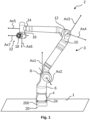
- Fig. 1 is a schematic diagram illustrating an exemplary robot 2, which in the present example comprises a robotic arm 3, more particularly, a seven-axis robotic arm.
- the robotic arm 3 extends between a base end 20 and a tool end 22 and comprising a base 4 at the base end 20.
- a tool flange for connection with a tool may preferably be arranged at the tool end 22 of the robotic arm.
- the robotic arm 3 further comprises a plurality of joints 6, 8, 10, 12, 14, 16, 18.
- the plurality of joints 6, 8, 10, 12, 14, 16, 18 connects the base 4 and the tool end 22.
- the plurality of joints are seven joints, i.e. including a first joint 6, a second joint 8, a third joint 10, a fourth joint 12, a fifth joint 14, a sixth joint 16 and a seventh joint 18.
- the robotic arm may comprise fewer or more joints.
- the robotic arm 3 may, in another configuration, comprise only three joints, such as the first, second and third joints 6, 8, 10.
- the first joint 6 is positioned between the base 4 and the second joint 8.
- the second joint 8 is positioned between the first joint 6 and the third joint 10.
- the third joint 10 is positioned between the second joint 8 and the fourth joint 12.
- the fourth joint 12 is positioned between the third joint 10 and the fifth joint 14.
- the fifth joint 14 is positioned between the fourth joint 12 and the sixth joint 16.
- the sixth joint 16 is positioned between the fifth joint 14 and the seventh joint 18.
- the seventh joint 18 is positioned between the sixth joint 16 and the tool end 22.
- the plurality of joints 6, 8, 10, 12, 14, 16, 18 cause movement of the robotic arm 3, e.g. movement of the tool end 22 relative to the base end 20.
- Each joint provides for rotation about a respective axis.
- the first joint 6 provides for rotation about a first axis Ax1.
- the second joint 8 provides for rotation about a second axis Ax2.
- the third joint 10 provides for rotation about a third axis Ax3.
- the fourth joint 12 provides for rotation about a fourth axis Ax4.
- the fifth joint 14 provides for rotation about a fifth axis Ax5.
- the sixth joint 16 provides for rotation about a sixth axis Ax6.
- the seventh joint 18 provides for rotation about a seventh axis Ax7.
- the robotic arm 3 may be put in some configurations, where none of the seven axes Ax1-Ax7 are parallel. However, in some other configurations two or more of the seven axes Ax1-Ax7 may be parallel. As illustrated, the second axis Ax2 may be non-parallel with the first axis Ax1. The third axis Ax3 may be non-parallel with the second axis Ax2. The fourth axis Ax4 may be non-parallel with the third axis Ax3. The fifth axis Ax5 may be non-parallel with the fourth axis Ax4. The sixth axis Ax6 may be non-parallel with the fifth axis Ax5. The seventh axis Ax7 may be non-parallel with the sixth axis Ax6.
- the robotic arm may comprise a plurality of motors as described in more detail relation to Fig. 2 , e.g. including a motor for each of the plurality of joints 6, 8, 10, 12, 14, 16, 18.
- Each of the plurality of motors may cause movement of a respective joint of the plurality of joints 6, 8, 10, 12, 14, 16, 18.
- a first motor may cause movement of the first joint 6 with respect to the first axis Ax1.
- a second motor may cause movement of the second joint 8 with respect to the second axis Ax2.
- a third motor may cause movement of the third joint 10 with respect to the third axis Ax3. And so forth.
- the robotic arm 3 is fastened at the base end 20 to a structure 1, which may be a factory floor or another structure from which the robotic arm 3 is meant to work from.
- the structure 1 may be part of a movable unit, such as a mobile robot or a vehicle, which would allow the robot 2 or at least the robotic arm 3 to be moved between different positions.
- the robotic arm 3 may be fastened to the structure 1 by fastening bolts 24.
- the robot 2 as illustrated, further comprises a control unit 200, which in the present example may form an integral part of the base 4 of the robotic arm 3 or may be adapted to be arranged between the base 4 and the structure 1.
- a control unit 200 which in the present example may form an integral part of the base 4 of the robotic arm 3 or may be adapted to be arranged between the base 4 and the structure 1.
- the present disclosure may alternatively be applied to a robot having only six axes, or even fewer axes.
- movement around the third axis Ax3 may be omitted, to obtain a robot operable relative to six axes.
- Fig. 2 is a schematic diagram illustrating two exemplary joints 92, 94, e.g. a primary joint 92 and a secondary joint 94.
- the exemplary joints 92, 94 may be two successive joints of the plurality of joints 6, 8, 10, 12, 14, 16, 18 indicated in Fig. 1 .
- the primary joint 92 may be the first joint 6 of Fig. 1 and the secondary joint 94 may be the second joint 8 of Fig. 1 .
- a primary motor 102 provided to rotate the primary joint 92.
- a secondary motor 104 is provided to rotate the secondary joint 94.
- the primary motor 102 may be a first motor for causing movement of the first joint 6 with respect to the first axis Ax1 of Fig. 1 .
- the secondary motor 104 may be a second motor for causing movement of the second joint 8 with respect to the second axis Ax2 of Fig. 1 .
- the primary motor 102 and/or the secondary motor 104 may be a permanent magnet AC motor.
- the primary motor 102 and/or the secondary motor 104 may comprise a gear assembly, e.g. an integral gear, such as a strain wave gear.
- the primary motor 102 and/or the secondary motor 104 may be a gear motor.
- One or more motor controller units 108, 110 may be provided and adapted to control the motors 102, 104.
- a primary motor controller unit 108 may be adapted to control the primary motor 102.
- a secondary motor controller unit 110 may be adapted to control the secondary motor 104.
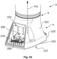
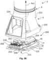
- Figs. 3A and 3B are schematic diagrams illustrating an exemplary base 4 of a robotic arm 3, such as the robotic arm 3 as illustrated in Fig. 1 . Also the first joint 6 is visible in Figs. 3A and 3B. Fig. 3B shows the upper part of the base 4 being separated from the bottom part to visualise internal parts of the base 4.
- the base 4 comprises a control unit 200.
- the control unit 200 comprises a main board 202 with a main processing unit 204.
- the control unit 200 also comprises an IO board 206 with a plurality of IO terminals 208.
- the IO terminals 208 may be terminal blocks.
- the IO terminals 208 may be 24 volts digital IO terminals.
- the control unit 200 also comprises a bottom plate 210 forming a bottom surface 212 of the control unit 200.
- the bottom plate 210 may be made of a material having a high thermal conductivity, such as at least 100 W/(m ⁇ K).
- the bottom plate 210 may be made of aluminium, copper or alloys of different materials, e.g. comprising aluminium and/or copper.
- the bottom plate may facilitate transfer of heat from the control unit 200 to the structure to which the robot is attached.
- the bottom plate 210 may be adapted to abut the structure to which the robot is to be fastened.
- the bottom plate 210 may be arranged perpendicular and/or substantially perpendicular to the first axis Ax1, i.e. the axis of rotation of the first joint 6.
- the main board 202 is arranged to form an angle of less than 135 degrees with respect to the first axis Ax1.
- the angle formed between the main board 202 and the first axis Ax1 is less than less than 120 degrees, such as less than 105 degrees, such as less than 100 degrees, such as less than 95 degrees.
- the angle formed between the main board 202 and the first axis Ax1 may be perpendicular or substantially perpendicular.
- the IO board 206 may be arranged between the bottom plate and the main board 202.
- the main board 202 and the IO board 206 may be substantially parallel.
- the control unit may comprise a plurality of main standoffs 214 connecting the main board 202 and the bottom plate 210.
- the main standoffs 214 may be sized such that the IO board 206 may be arranged between the bottom plate 210 and the main board 206.
- the main standoffs 214 connecting the main board 202 and the bottom plate 210 may be more than 1 cm, such as more than 2 cm, such as more than 3 cm.
- the control unit may comprise a plurality of IO standoffs 215 connecting the IO board 206 and the bottom plate 210.
- the IO standoffs 215 may be smaller than the main standoffs 214.
- the IO standoffs 215 may be less than 2 cm, such as less than 1 cm.
- the plurality of IO terminals 208 may have a connection direction 218, i.e. the direction in which wires and/or connectors are being connected to the terminals.
- the connection direction 218 may, as illustrated, be substantially parallel to the first axis Ax1.
- the connection direction 218 may also or alternatively be substantially perpendicular to the IO board 206 and/or the main board 202.
- the main board 202 has a main board length d1 along a length direction of the main board, e.g. perpendicular to the first axis Ax1.
- the IO board 206 has an IO board length d2 along a length direction of the IO board, which may be the same direction as the length direction of the main board, e.g. perpendicular to the first axis Ax1.
- the IO board length d2 may be longer than the main board length d1.
- the IO terminals 208 may be easily accessible, even though the IO board 206 may be provided underneath the main board 202, such as between the main board 202 and the bottom plate 210.
- the bottom plate 210 has a bottom plate circumference and the base 4 has a first joint circumference at the first joint 6.
- the bottom plate 210 has a bottom plate diameter, which is the diameter of the incircle of the bottom plate circumference.
- the base 4 has a first joint diameter of the first joint circumference at the first joint 6.
- the bottom plate circumference, the first joint circumference, the bottom plate diameter and the first joint diameter are measured in the plane normal to the first axis Ax1.
- the bottom plate circumference is larger than the first joint circumference and/or the bottom plate diameter is larger than the first joint diameter.
- the base 4 has a first wall section 220 being substantially parallel to the first axis Ax1.
- the base 4 has a second wall section 222 extending from the first wall section 220 towards the first joint 6.
- the second wall section 222 is non-parallel to the first axis Ax1.
- the second wall section 222 may be angled relative to the first axis Ax1, e.g. to transition the base 4 from the bottom plate circumference to the first joint circumference.
- the base 4 comprises a base aperture 224 providing access to the plurality of IO terminals 208.
- the base 4 further may comprise a removable cover plate 226 covering the base aperture, as illustrated in Fig. 5 .
- the base aperture 224 and/or the removable cover plate 226 may be angled relative to the first axis Ax1. Such angled aperture/cover plate may facilitate interaction with the IO terminals 208.
- an angle between the first axis Ax1 and the base aperture 224 and/or the removable cover plate 226 may be between 10 and 60 degrees, such as between 20 and 50 degrees, such as between 25 and 40 degrees.
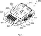
- Fig. 4 is a schematic diagram illustrating an exemplary control unit 200, such as the control unit 200 as also illustrated in Figs. 3A and 3B .
- Fig. 4 further illustrates that the control unit 200 may comprise a heat transferring block 216 thermally connecting the main processing unit 204 and the bottom plate 210.
- the heat transferring block 216 may be made of a material having a high thermal conductivity, such as at least 100 W/(m ⁇ K).
- the heat transferring block 216 may be made of aluminium, copper or alloys of different materials, e.g. comprising aluminium and/or copper.
- the heat transferring block 216 may be integrally formed with the bottom plate 210.
- the IO board 206 may comprise an opening 217 for the heat transferring block 216 to extend through. Thereby allowing the hat transferring block 216 to extend from the main processing unit 204 and the bottom plate 210, even when the IO board 206 is positioned between the main board 202 and the bottom plate 210.
- control unit comprises an electrical power input 236 adapted to electrically power electrical components of the robotic arm, such as the plurality of motors and/or electronic circuitries of the robotic arm.
- the IO board comprises two IO processing units 209, where a first of the two IO processing units 209 are preferably electrically connected to a primary IO terminal of the IO terminals 208 and a second of the two IO processing units 209 are preferably electrically connected to a secondary IO terminal of the IO terminals 208, such as to facilitate safe provision of input/output signals and handling thereof, e.g. in compliance with safety standards, such as ISO 13849-1.
- the two processing units 209 may be two processor cores of the same chip. However, in other examples, the two processing units 209 may be separate chips.
- the bottom plate 210 may comprise a bottom plate aperture 228.
- the bottom plate 210 comprise two bottom plate apertures 228.
- the one or more bottom plate apertures 228 may form a passageway for wires being connected to the IO terminals 208.
- wires connected to the IO terminals 208 may be routed out from the control unit 200 through the bottom plate 210.
- wires extending from the base 4 of the robot may be limited.
- control unit 200 may comprise one or more energy consumption unit 234 adapted to handle excess electrical power on a power bus of the robot, e.g. due to motors of the robot generating energy in situations where they are braking an ongoing motion.
- the energy consumption units 234 may be arranged at the bottom plate 210.
- the energy consumption units 234 have for simplicity been left out from figures 3A and 3B .
- Fig. 5 schematically illustrates the base 4 of the robotic arm 3, as previously described, where the base aperture 224 is covered by a removable cover plate 226.
- the cover plate may comprise cover plate openings 230 to form a passageway for wires being connected to the IO terminals, e.g. as an alternative to routing wires through the bottom plate aperture 228 as illustrated in Fig. 4 .
- the cover plate 226 may be provided without cover plate openings 230, and the customer may decide where or whether to provide a cover plate opening 230 in the cover plate 226.
- Fig. 6A schematically illustrates the base 4 of the robot with an alternative control unit 200.
- the control unit 200 is further schematically illustrated in a separated view in Fig. 6B without the cover of the base 4.
- the exemplary control unit 200 of Figs. 6A and 6b comprises the same elements as the control unit 200 as illustrated and described in relation to the previous figures.
- the control unit 200 comprises a main board 202 with a main processing unit 204 and an IO board 206 with a plurality of IO terminals 208 and two IO processing units 209.
- the arrangement of elements may differ as described in the following.
- the control unit 200 also comprises the bottom plate 210, which like for the previously described example, may be made of a material having a high thermal conductivity, such as to facilitate transfer of heat from the control unit 200 to the structure to which the robot is attached.
- the bottom plate 210 may, like with the previously described example, be arranged perpendicular and/or substantially perpendicular to the first axis Ax1.
- the main board 202 may be arranged to form an angle of less than 135 degrees, or substantially perpendicularly, with respect to the first axis Ax1.
- the main board 202 is arranged between the bottom plate 210 and the IO board 206.
- the IO board 206 comprises a first IO board part 206A and a second IO board part 206B.
- the second IO board part 206B comprises the IO terminals 208.
- the first IO board part 206A is non-parallel to the second IO board part 206B.
- the first IO board part 206A may be angled relative to the second IO board part 206B by between 70-90 degrees, such as between 80-90 degrees.
- the first IO board part 206A may be perpendicular to the second IO board part 206B.
- the main board 202 and the first IO board part 206A may be substantially parallel.
- the second IO board part 206B and the first axis Ax1 may be substantially parallel.
- the plurality of IO terminals 208 has a connection direction 218, i.e. the direction in which wires and/or connectors are being connected to the terminals, which may be substantially perpendicular to the first axis Ax1.
- the connection direction 218 may also or alternatively be substantially perpendicular to the second IO board part 206B.
- the second IO board part 206B has a second IO board part length d4 along the first axis Ax1 from the first IO board part 206A.
- the first motor 232 is being spaced from the first IO board part 206A by a first motor to first IO board part distance d3.
- the second IO board part length d4 is longer than the first motor to first IO board part distance d3. This means that the control unit 200 may be made more compact, since the second IO board part extends along the side of the first motor 232.
- the base 4 has a first wall section 220 being substantially parallel to the first axis Ax1 and a second wall section 222 extending from the first wall section 220 towards the first joint 6. Furthermore, the base 4 comprises a base aperture 224, which may be covered by a removable cover plate 226, as illustrated in Fig. 5 . Furthermore, like for the previous examples, the bottom plate 210 may comprise one or more bottom plate aperture 228 to form a passageway for wires being connected to the IO terminals 208.
- first, second, third, “fourth”, “primary”, “secondary”, “tertiary” etc. does not imply any particular order or importance but are included to identify individual elements. Furthermore, the labelling of a first element does not imply the presence of a second element and vice versa.
Landscapes
- Engineering & Computer Science (AREA)
- Robotics (AREA)
- Mechanical Engineering (AREA)
- Manipulator (AREA)
Priority Applications (4)
| Application Number | Priority Date | Filing Date | Title |
|---|---|---|---|
| EP23179997.4A EP4480641B1 (en) | 2023-06-19 | 2023-06-19 | Robotic arm with an integrated control unit |
| ES23179997T ES3026547T3 (en) | 2023-06-19 | 2023-06-19 | Robotic arm with an integrated control unit |
| PL23179997.4T PL4480641T3 (pl) | 2023-06-19 | 2023-06-19 | Ramię robotyczne ze zintegrowaną jednostką sterującą |
| PCT/EP2024/066965 WO2024260989A1 (en) | 2023-06-19 | 2024-06-18 | Robotic arm with an integrated control unit |
Applications Claiming Priority (1)
| Application Number | Priority Date | Filing Date | Title |
|---|---|---|---|
| EP23179997.4A EP4480641B1 (en) | 2023-06-19 | 2023-06-19 | Robotic arm with an integrated control unit |
Publications (3)
| Publication Number | Publication Date |
|---|---|
| EP4480641A1 EP4480641A1 (en) | 2024-12-25 |
| EP4480641C0 EP4480641C0 (en) | 2025-04-30 |
| EP4480641B1 true EP4480641B1 (en) | 2025-04-30 |
Family
ID=86899098
Family Applications (1)
| Application Number | Title | Priority Date | Filing Date |
|---|---|---|---|
| EP23179997.4A Active EP4480641B1 (en) | 2023-06-19 | 2023-06-19 | Robotic arm with an integrated control unit |
Country Status (4)
| Country | Link |
|---|---|
| EP (1) | EP4480641B1 (pl) |
| ES (1) | ES3026547T3 (pl) |
| PL (1) | PL4480641T3 (pl) |
| WO (1) | WO2024260989A1 (pl) |
Family Cites Families (6)
| Publication number | Priority date | Publication date | Assignee | Title |
|---|---|---|---|---|
| US9346160B2 (en) * | 2013-06-24 | 2016-05-24 | Redwood Robotics, Inc. | Modular reconfigurable workcell for quick connection of peripherals |
| JP6455050B2 (ja) * | 2014-09-30 | 2019-01-23 | セイコーエプソン株式会社 | ロボット |
| JP6722099B2 (ja) * | 2016-12-09 | 2020-07-15 | 株式会社ダイヘン | 搬送システム |
| JP7130932B2 (ja) * | 2017-09-29 | 2022-09-06 | セイコーエプソン株式会社 | ロボット |
| JP7400211B2 (ja) * | 2019-05-16 | 2023-12-19 | セイコーエプソン株式会社 | ロボットシステム、制御装置およびロボットの制御方法 |
| JP2023073759A (ja) * | 2021-11-16 | 2023-05-26 | キヤノン株式会社 | ロボット、ロボットの制御方法、ロボットを用いた物品の製造方法、制御プログラムおよび記録媒体 |
-
2023
- 2023-06-19 PL PL23179997.4T patent/PL4480641T3/pl unknown
- 2023-06-19 ES ES23179997T patent/ES3026547T3/es active Active
- 2023-06-19 EP EP23179997.4A patent/EP4480641B1/en active Active
-
2024
- 2024-06-18 WO PCT/EP2024/066965 patent/WO2024260989A1/en active Pending
Also Published As
| Publication number | Publication date |
|---|---|
| EP4480641C0 (en) | 2025-04-30 |
| ES3026547T3 (en) | 2025-06-11 |
| PL4480641T3 (pl) | 2025-08-11 |
| WO2024260989A1 (en) | 2024-12-26 |
| EP4480641A1 (en) | 2024-12-25 |
Similar Documents
| Publication | Publication Date | Title |
|---|---|---|
| Hirzinger et al. | On a new generation of torque controlled light-weight robots | |
| CN104608125B (zh) | 机器人、控制装置以及机器人系统 | |
| EP3372354B1 (en) | Modular robotic joint and reconfigurable robot made using the same | |
| US9409293B2 (en) | Robot | |
| US20060177295A1 (en) | Buckling arm robot | |
| US20070039831A1 (en) | Process for anodizing a robotic device | |
| CN108000477A (zh) | 一种全位姿主被动柔顺机器人及利用该机器人的旋拧阀门方法 | |
| JPH03502507A (ja) | モジュール型ロボット装置 | |
| JPS63174894A (ja) | デジタルロボット制御装置 | |
| EP1793292B1 (en) | Robot controller system | |
| KR20090049651A (ko) | 내장형 로봇 제어 시스템 | |
| CN103302657A (zh) | 用于机器人的标定方法和标定系统 | |
| KR20190120838A (ko) | 로봇 매니퓰레이터 | |
| EP4480641B1 (en) | Robotic arm with an integrated control unit | |
| CN116457164A (zh) | 机器人 | |
| JP2020127995A (ja) | ロボットシステム、ロボットシステムの制御方法およびロボットコントローラー | |
| JPH05237775A (ja) | リンク機構を備えたロボット | |
| JP2019010683A (ja) | ロボット制御装置およびロボットシステム | |
| CN112088071B (zh) | 机器人组件 | |
| EP4363170B1 (en) | Integrated control unit | |
| CN115302504A (zh) | 一种支持肩腕互换可移动机械臂的分布式控制系统 | |
| WO2025125218A1 (en) | Robotic arm with an integrated control unit | |
| CN220389440U (zh) | 用于平面移载的模块化机器人 | |
| Mihelj et al. | yControl-open architecture controller for Yaskawa Motoman MH5 robot | |
| Hirzinger et al. | Space Robotics-Driver for a new mechatronic Generation of light-weight arms and multifingered hands |
Legal Events
| Date | Code | Title | Description |
|---|---|---|---|
| STAA | Information on the status of an ep patent application or granted ep patent |
Free format text: STATUS: EXAMINATION IS IN PROGRESS |
|
| PUAI | Public reference made under article 153(3) epc to a published international application that has entered the european phase |
Free format text: ORIGINAL CODE: 0009012 |
|
| 17P | Request for examination filed |
Effective date: 20240109 |
|
| AK | Designated contracting states |
Kind code of ref document: A1 Designated state(s): AL AT BE BG CH CY CZ DE DK EE ES FI FR GB GR HR HU IE IS IT LI LT LU LV MC ME MK MT NL NO PL PT RO RS SE SI SK SM TR |
|
| GRAP | Despatch of communication of intention to grant a patent |
Free format text: ORIGINAL CODE: EPIDOSNIGR1 |
|
| STAA | Information on the status of an ep patent application or granted ep patent |
Free format text: STATUS: GRANT OF PATENT IS INTENDED |
|
| INTG | Intention to grant announced |
Effective date: 20250113 |
|
| GRAS | Grant fee paid |
Free format text: ORIGINAL CODE: EPIDOSNIGR3 |
|
| GRAA | (expected) grant |
Free format text: ORIGINAL CODE: 0009210 |
|
| STAA | Information on the status of an ep patent application or granted ep patent |
Free format text: STATUS: THE PATENT HAS BEEN GRANTED |
|
| AK | Designated contracting states |
Kind code of ref document: B1 Designated state(s): AL AT BE BG CH CY CZ DE DK EE ES FI FR GB GR HR HU IE IS IT LI LT LU LV MC ME MK MT NL NO PL PT RO RS SE SI SK SM TR |
|
| REG | Reference to a national code |
Ref country code: CH Ref legal event code: EP Ref country code: GB Ref legal event code: FG4D |
|
| REG | Reference to a national code |
Ref country code: IE Ref legal event code: FG4D |
|
| REG | Reference to a national code |
Ref country code: DE Ref legal event code: R096 Ref document number: 602023003146 Country of ref document: DE |
|
| REG | Reference to a national code |
Ref country code: ES Ref legal event code: FG2A Ref document number: 3026547 Country of ref document: ES Kind code of ref document: T3 Effective date: 20250611 |
|
| U01 | Request for unitary effect filed |
Effective date: 20250508 |
|
| U07 | Unitary effect registered |
Designated state(s): AT BE BG DE DK EE FI FR IT LT LU LV MT NL PT RO SE SI Effective date: 20250515 |
|
| U20 | Renewal fee for the european patent with unitary effect paid |
Year of fee payment: 3 Effective date: 20250625 |
|
| PGFP | Annual fee paid to national office [announced via postgrant information from national office to epo] |
Ref country code: ES Payment date: 20250701 Year of fee payment: 3 |
|
| PG25 | Lapsed in a contracting state [announced via postgrant information from national office to epo] |
Ref country code: NO Free format text: LAPSE BECAUSE OF FAILURE TO SUBMIT A TRANSLATION OF THE DESCRIPTION OR TO PAY THE FEE WITHIN THE PRESCRIBED TIME-LIMIT Effective date: 20250730 Ref country code: GR Free format text: LAPSE BECAUSE OF FAILURE TO SUBMIT A TRANSLATION OF THE DESCRIPTION OR TO PAY THE FEE WITHIN THE PRESCRIBED TIME-LIMIT Effective date: 20250731 |
|
| PGFP | Annual fee paid to national office [announced via postgrant information from national office to epo] |
Ref country code: PL Payment date: 20250606 Year of fee payment: 3 |
|
| PG25 | Lapsed in a contracting state [announced via postgrant information from national office to epo] |
Ref country code: HR Free format text: LAPSE BECAUSE OF FAILURE TO SUBMIT A TRANSLATION OF THE DESCRIPTION OR TO PAY THE FEE WITHIN THE PRESCRIBED TIME-LIMIT Effective date: 20250430 |
|
| PG25 | Lapsed in a contracting state [announced via postgrant information from national office to epo] |
Ref country code: RS Free format text: LAPSE BECAUSE OF FAILURE TO SUBMIT A TRANSLATION OF THE DESCRIPTION OR TO PAY THE FEE WITHIN THE PRESCRIBED TIME-LIMIT Effective date: 20250731 |
|
| PG25 | Lapsed in a contracting state [announced via postgrant information from national office to epo] |
Ref country code: IS Free format text: LAPSE BECAUSE OF FAILURE TO SUBMIT A TRANSLATION OF THE DESCRIPTION OR TO PAY THE FEE WITHIN THE PRESCRIBED TIME-LIMIT Effective date: 20250830 |