EP4480592A1 - Hochdruckreinigungsgerät - Google Patents
Hochdruckreinigungsgerät Download PDFInfo
- Publication number
- EP4480592A1 EP4480592A1 EP23180026.9A EP23180026A EP4480592A1 EP 4480592 A1 EP4480592 A1 EP 4480592A1 EP 23180026 A EP23180026 A EP 23180026A EP 4480592 A1 EP4480592 A1 EP 4480592A1
- Authority
- EP
- European Patent Office
- Prior art keywords
- valve
- start valve
- pressure
- cleaning device
- main line
- Prior art date
- Legal status (The legal status is an assumption and is not a legal conclusion. Google has not performed a legal analysis and makes no representation as to the accuracy of the status listed.)
- Pending
Links
Images

Classifications
-
- B—PERFORMING OPERATIONS; TRANSPORTING
- B08—CLEANING
- B08B—CLEANING IN GENERAL; PREVENTION OF FOULING IN GENERAL
- B08B3/00—Cleaning by methods involving the use or presence of liquid or steam
- B08B3/02—Cleaning by the force of jets or sprays
- B08B3/026—Cleaning by making use of hand-held spray guns; Fluid preparations therefor
-
- B—PERFORMING OPERATIONS; TRANSPORTING
- B05—SPRAYING OR ATOMISING IN GENERAL; APPLYING FLUENT MATERIALS TO SURFACES, IN GENERAL
- B05B—SPRAYING APPARATUS; ATOMISING APPARATUS; NOZZLES
- B05B9/00—Spraying apparatus for discharge of liquids or other fluent material, without essentially mixing with gas or vapour
- B05B9/03—Spraying apparatus for discharge of liquids or other fluent material, without essentially mixing with gas or vapour characterised by means for supplying liquid or other fluent material
- B05B9/04—Spraying apparatus for discharge of liquids or other fluent material, without essentially mixing with gas or vapour characterised by means for supplying liquid or other fluent material with pressurised or compressible container; with pump
- B05B9/0403—Spraying apparatus for discharge of liquids or other fluent material, without essentially mixing with gas or vapour characterised by means for supplying liquid or other fluent material with pressurised or compressible container; with pump with pumps for liquids or other fluent material
- B05B9/0426—Spraying apparatus for discharge of liquids or other fluent material, without essentially mixing with gas or vapour characterised by means for supplying liquid or other fluent material with pressurised or compressible container; with pump with pumps for liquids or other fluent material with a pump attached to the spray gun or discharge device
-
- F—MECHANICAL ENGINEERING; LIGHTING; HEATING; WEAPONS; BLASTING
- F04—POSITIVE - DISPLACEMENT MACHINES FOR LIQUIDS; PUMPS FOR LIQUIDS OR ELASTIC FLUIDS
- F04B—POSITIVE-DISPLACEMENT MACHINES FOR LIQUIDS; PUMPS
- F04B49/00—Control, e.g. of pump delivery, or pump pressure of, or safety measures for, machines, pumps, or pumping installations, not otherwise provided for, or of interest apart from, groups F04B1/00 - F04B47/00
- F04B49/02—Stopping, starting, unloading or idling control
- F04B49/03—Stopping, starting, unloading or idling control by means of valves
-
- F—MECHANICAL ENGINEERING; LIGHTING; HEATING; WEAPONS; BLASTING
- F04—POSITIVE - DISPLACEMENT MACHINES FOR LIQUIDS; PUMPS FOR LIQUIDS OR ELASTIC FLUIDS
- F04B—POSITIVE-DISPLACEMENT MACHINES FOR LIQUIDS; PUMPS
- F04B49/00—Control, e.g. of pump delivery, or pump pressure of, or safety measures for, machines, pumps, or pumping installations, not otherwise provided for, or of interest apart from, groups F04B1/00 - F04B47/00
- F04B49/22—Control, e.g. of pump delivery, or pump pressure of, or safety measures for, machines, pumps, or pumping installations, not otherwise provided for, or of interest apart from, groups F04B1/00 - F04B47/00 by means of valves
- F04B49/24—Bypassing
-
- F—MECHANICAL ENGINEERING; LIGHTING; HEATING; WEAPONS; BLASTING
- F04—POSITIVE - DISPLACEMENT MACHINES FOR LIQUIDS; PUMPS FOR LIQUIDS OR ELASTIC FLUIDS
- F04B—POSITIVE-DISPLACEMENT MACHINES FOR LIQUIDS; PUMPS
- F04B53/00—Component parts, details or accessories not provided for in, or of interest apart from, groups F04B1/00 - F04B23/00 or F04B39/00 - F04B47/00
- F04B53/10—Valves; Arrangement of valves
-
- F—MECHANICAL ENGINEERING; LIGHTING; HEATING; WEAPONS; BLASTING
- F16—ENGINEERING ELEMENTS AND UNITS; GENERAL MEASURES FOR PRODUCING AND MAINTAINING EFFECTIVE FUNCTIONING OF MACHINES OR INSTALLATIONS; THERMAL INSULATION IN GENERAL
- F16K—VALVES; TAPS; COCKS; ACTUATING-FLOATS; DEVICES FOR VENTING OR AERATING
- F16K17/00—Safety valves; Equalising valves, e.g. pressure relief valves
- F16K17/20—Excess-flow valves
- F16K17/22—Excess-flow valves actuated by the difference of pressure between two places in the flow line
- F16K17/24—Excess-flow valves actuated by the difference of pressure between two places in the flow line acting directly on the cutting-off member
- F16K17/28—Excess-flow valves actuated by the difference of pressure between two places in the flow line acting directly on the cutting-off member operating in one direction only
- F16K17/30—Excess-flow valves actuated by the difference of pressure between two places in the flow line acting directly on the cutting-off member operating in one direction only spring-loaded
-
- F—MECHANICAL ENGINEERING; LIGHTING; HEATING; WEAPONS; BLASTING
- F16—ENGINEERING ELEMENTS AND UNITS; GENERAL MEASURES FOR PRODUCING AND MAINTAINING EFFECTIVE FUNCTIONING OF MACHINES OR INSTALLATIONS; THERMAL INSULATION IN GENERAL
- F16K—VALVES; TAPS; COCKS; ACTUATING-FLOATS; DEVICES FOR VENTING OR AERATING
- F16K17/00—Safety valves; Equalising valves, e.g. pressure relief valves
- F16K17/20—Excess-flow valves
- F16K17/34—Excess-flow valves in which the flow-energy of the flowing medium actuates the closing mechanism
-
- B—PERFORMING OPERATIONS; TRANSPORTING
- B08—CLEANING
- B08B—CLEANING IN GENERAL; PREVENTION OF FOULING IN GENERAL
- B08B2203/00—Details of cleaning machines or methods involving the use or presence of liquid or steam
- B08B2203/02—Details of machines or methods for cleaning by the force of jets or sprays
- B08B2203/0205—Bypass pressure relief valves
Definitions
- the invention relates to a high-pressure cleaning device according to the preamble of claim 1.
- a return line with a start valve can be provided between the pressure chamber and the suction chamber.
- the high-pressure cleaning device is designed in such a way that the start valve closes in such a way that no liquid can flow through the return line from the pressure chamber into the suction chamber if the volume flow through the start valve corresponds to at least a start volume threshold. Below the start volume threshold, however, liquid can flow through the return line. This makes it easier to start up the high-pressure pump or the motor of the high-pressure pump. The high-pressure pump does not then have to work against a high pressure in the pressure chamber, especially when the main line valve is closed.
- the high-pressure pump can pump liquid in a circle via the return line from the pressure chamber into the suction chamber without having to work against a high counter pressure with an initially low torque or low speed. In this way, the pump can reach a speed at which it can then provide sufficient torque with a corresponding counter pressure until the start volume threshold is reached and the start valve closes. Only after the high-pressure pump or motor has reached this speed does it have to work against a greater pressure in the pressure chamber. With high-pressure cleaning devices from the state of the art, it can happen that the motor overheats and stops when trying to start it, despite the start valve.
- the invention is based on the object of developing a generic high-pressure cleaning device in such a way that reliable starting of the motor of the high-pressure pump is ensured.
- the invention is based on the finding that the point in time or the speed value at which the start valve closes due to the start volume threshold being reached is not always reliably reproducible in the high-pressure cleaning devices known to date under largely unchanged operating conditions. In cases where the engine overheats and stops, the start valve is closed before the engine has reached a speed in its working range.
- the invention is also based on the knowledge that in high-pressure cleaning devices from the prior art, the volume flow in the return line also depends on external parameters such as the nozzle cross-section at the spray opening and other throttling in the main line.
- the return line is a branch line of the main line between the high-pressure pump and the spray opening. The volume flow is divided at this branch. The proportion of the volume flow that is branched off into the return line before the branch depends on external parameters. This explains why, under otherwise constant operating conditions, the closing and opening times of the start valve arranged in the return line, or the speed values of the engine at which the start valve opens or closes, vary.
- the invention provides for arranging the start valve in the main line downstream of the high-pressure pump.
- the start valve By arranging the start valve in the main line, the full, undivided volume flow of the liquid hits the start valve. Since no part of the volume flow was branched off from the main line before the volume flow hits the start valve, the start valve closes and opens reliably. The parameter that determines whether the start valve closes and opens is reliably reproducible in the invention. Since the volume flow hitting the start valve is undivided, external parameters that influence how large the branched portion of the volume flow into the return line is do not play a role. In particular, the volume flow at the start valve is independent of the nozzle cross-section of the nozzle used at the ejection opening.
- the times or the speeds of the engine at which the start valve opens and closes are also reproducible. This means that the pressure against which the high-pressure pump has to work when starting up is also reproducible.
- the arrangement of the start valve in the main line allows the start valve to work reliably and reproducibly. Accordingly, the start valve only closes reliably when the engine has reached a speed in its working speed range when starting up.
- the start valve is advantageously located upstream of the return line in the main line. This ensures that no part of the volume flow is diverted into the return line before the volume flow hits the start valve. This results in reproducible conditions for the start valve. The full volume flow is available to switch the start valve.
- the start valve is arranged outside the return line. This prevents a portion of the volume flow from branching off through the main line into the return line before it hits the start valve.
- the main line in the area between the high-pressure pump and the spray opening is the line of the high-pressure cleaning device in which the liquid travels the shortest route from the high-pressure pump to the spray opening. Branches from the main line in which the liquid may flow back and forth are not included in the main line.
- the high-pressure cleaning device has a main flow path. The liquid flows along the main flow path from the connection for the liquid source to the ejection opening. The main flow path runs along the main line.
- the start valve is arranged in particular in the main flow path.
- the high-pressure cleaning device is expediently designed such that when the high-pressure cleaning device is operated, the liquid flows through the start valve with a volume flow below the start volume threshold value without the possibility of branching from the high-pressure pump to the start valve in the main line.
- the high-pressure cleaning device is designed such that when the high-pressure cleaning device is operated, the liquid flows through the start valve with no possibility of branching from the high-pressure pump to the start valve in the main line, regardless of the volume flow.
- the start valve is designed in such a way that it allows the flow of liquid from the pressure chamber into the return line when the volume flow through the start valve is below the start volume threshold. This enables the high-pressure pump or the motor of the high-pressure pump to start easily.
- the high-pressure pump or the motor does not have to work against a high pressure in the pressure chamber during start-up. This is particularly advantageous when the main line valve is closed.
- the start valve is designed in such a way that it stops the flow of liquid from the pressure chamber into the return line when the volume flow through the start valve is at least equal to the start volume threshold. This allows sufficient pressure to build up in the pressure chamber after the start volume threshold has been reached. Cleaning with the high-pressure cleaning device is then possible. Because the start valve only stops the flow of liquid from the pressure chamber into the return line after the start volume threshold has been reached, the motor of the high-pressure pump can initially reach a sufficient speed. at which it can generate sufficient torque to work against a corresponding pressure in the pressure chamber. This prevents the motor and the high-pressure pump from failing during start-up. It also prevents the motor from not reaching the sufficient speed at all because the pressure against which the pump or motor has to work is too great.
- the start valve located in the main line divides the pressure chamber of the main line into a pump section and an ejection section.
- the pump section is arranged between the high-pressure pump and the start valve.
- the ejection section is arranged between the start valve and the ejection opening.
- the start valve is advantageously designed in such a way that it allows a direct flow of liquid from the pump section into the ejection section when the volume flow through the start valve is at least equal to the start volume threshold value.
- this direct flow from the pump section into the ejection section takes place without the detour via the return line.
- the liquid transfers from the pump section to the ejection section without branching off a portion of the volume flow, for example into the return line.
- the pressure generated by the high-pressure pump in the pressure chamber is independent of the portion of the volume flow that is branched off into a return line. This contributes to reproducible operating conditions.
- the start valve has an inlet.
- the inlet is connected in particular to the main line.
- the inlet is expediently connected directly to the main line.
- the inlet is connected in particular to the pump section of the pressure chamber of the main line.
- the start valve has a return outlet.
- the return outlet is connected in particular to the return line.
- the start valve has a main line outlet.
- the main line outlet is connected in particular to the main line.
- the main line outlet is connected to the spray section of the pressure chamber of the main line.
- the high-pressure cleaning device is expediently designed so that the start valve closes the return outlet, if the volume flow through the start valve is at least equal to the start volume threshold.
- the start valve has a valve element.
- the liquid conveyed by the high-pressure pump from the connection to the ejection opening through the main line hits the start valve in the main line in a flow direction.
- the high-pressure cleaning device is designed so that the flow direction at the point where the liquid hits the start valve runs parallel to the main line.
- the high-pressure cleaning device comprises a stop element for the valve member.
- the valve member is expediently pre-tensioned in the direction of the stop element.
- the high-pressure cleaning device is designed in such a way that the valve member rests against the stop element when the volume flow through the start valve falls below a resting volume threshold. The valve member is thereby pressed against the stop element with a defined pressure.
- defined force ratios prevail when the valve member rests against the stop element.
- the valve member rests against the stop element when the valve member is not loaded by the liquid. Due to the stop element and the contact of the valve member with the stop element, the pressure that must be applied by the volume flow to move the valve member away from the stop element is clearly defined. This contributes to reproducible working conditions of the high-pressure cleaning device.
- the valve element advantageously has an inflow surface.
- the inflow surface is advantageously aligned transversely, in particular perpendicularly to the direction of flow. This results in particularly good force and pressure transfer through the liquid to the valve element.
- the inflow surface of the valve element is advantageously arranged completely in the main line.
- valve member is movable in a direction of movement.
- the direction of movement is expediently in the direction of the flow direction. This also contributes to good pressure transfer from the liquid to the valve member. It can be provided that the direction of movement of the valve member runs in the direction of an axial direction of the start valve. In particular, the axial direction of the start valve runs in the longitudinal direction of the start valve.
- valve member is arranged completely in the main line, in particular completely outside the return line.
- the valve member has a circumferential surface facing an inner wall of the start valve.
- a gap is expediently formed between the circumferential surface and the inner wall, which forms a minimum free cross-sectional area.
- the minimum free cross-sectional area is the smallest area through which the volume flow flows in the start valve.
- the minimum free cross-sectional area does not necessarily have to run perpendicular to the main line. However, it is perpendicular to the flow direction of the volume flow through the start valve at the location of the minimum free cross-sectional area.
- the start valve has an inlet surface.
- the inlet surface is oriented perpendicular to the flow direction.
- the liquid enters the start valve through the inlet surface.
- the valve member expediently allows the minimum free cross-sectional area through the main line below the resting volume threshold value, in particular in the state not loaded by the liquid.
- the minimum free cross-sectional area expediently amounts to at least 5%, preferably at least 10% of the inlet surface. This makes it possible for liquid to flow through the start valve even below the resting volume threshold value, in particular in the state not loaded by the liquid. Because the start valve does not close the main line below the resting volume threshold value, the valve member can be easily moved from its rest position. During or after the high-pressure pump or motor starts up, the valve member can then be easily moved from its rest position, in particular pushed away from the stop element. This prevents the valve element from sticking or becoming stuck.
- the minimum free cross-sectional area is at most 70%, in particular at most 60% of the inlet area. This allows enough pressure from the liquid to act on the valve member. The valve member can be easily moved from its rest position.
- the circumferential surface has several recesses distributed over the circumference.
- the circumferential surface has a smallest gap distance measured perpendicular to the inner wall of the start valve.
- the recesses have a largest recess distance measured perpendicular to the inner wall of the start valve.
- the largest recess distance is expediently at least twice the smallest gap distance.
- valve member is movable in the direction of flow for closing a valve seat of the start valve.
- valve seat is expediently arranged at an inlet of the return line.
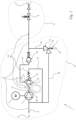
- Fig. 1 shows a high-pressure cleaning device 1 in a schematic representation.
- the high-pressure cleaning device 1 comprises a pump unit 16 and an ejection unit 11.
- the pump unit 16 and the ejection unit 11 are fluidically connected to one another via a main line 5.
- the ejection unit 11 comprises a gun (not shown). However, it can also be provided that the ejection unit comprises a gun and a lance.
- the high-pressure cleaning device 1 comprises a connection 2 for a liquid source.
- the liquid source is an external liquid source.
- the external liquid source can be, for example, a domestic water network. However, it can also be provided that the liquid source is an integral part of the high-pressure cleaning device.
- the high-pressure cleaning device 1 comprises an ejection opening 6.
- the high-pressure cleaning device 1 comprises the main line 5.
- the main line 5 of the high-pressure cleaning device 1 fluidically connects the connection 2 to the ejection opening 6.
- the connection 2 is arranged on the pump unit 16.
- the ejection opening 6 is arranged on the ejection unit 11.
- the ejection opening 6 is arranged on the ejection unit 11 designed as a gun.
- the ejection opening 6 is arranged on an exchangeable lance of the ejection unit 11.
- the high-pressure cleaning device 1 comprises a high-pressure pump 3.
- liquid can be conveyed through the main line 5 from the connection 2 to the injection opening 6.
- the liquid source supplies liquid to the main line 5.
- the high-pressure pump 3 is arranged in the main line 5.
- the high-pressure pump 3 pressurizes the liquid.
- the main line 5 has a suction chamber 9 and a pressure chamber 10.
- the high-pressure pump 3 is arranged between the suction chamber 9 and the pressure chamber 10 of the main line 5.
- the main line 5 has the suction chamber 9 between the connection 2 and the high-pressure pump 3.
- the main line 5 has the pressure chamber 10 between the high-pressure pump 3 and the injection opening 6.
- the suction chamber 9 is formed by a section of the main line 5 between the connection 2 and the high-pressure pump 3.
- the pressure chamber 10 is formed by a section of the main line 5 between the high-pressure pump 3 and the injection opening 6.
- the high-pressure pump 3 conveys liquid from the suction chamber 9 to the pressure chamber 10.
- the suction chamber 9 and the pressure chamber 10 are components of the main line 5. Downstream of the high-pressure pump 3, there is a higher pressure in the main line 5 when the high-pressure pump 3 is operating than upstream of the high-pressure pump 3.
- the high-pressure pump 3 is arranged in the pump unit 16.
- the high-pressure cleaning device 1 has a motor 4.
- the Motor 4 is arranged in the pump unit 16.
- the motor 4 can be designed as a brushless direct current motor.
- a brushless direct current motor is also referred to as an EC motor.
- the motor 4 can also be a universal motor.
- the motor 4 is an induction motor.
- the induction motor in the exemplary embodiment is operated with alternating current.
- the voltage source can be provided by the mains voltage, for example. If battery operation is intended, the motor can also be a brushless direct current motor. It can be provided that the battery is part of the high-pressure cleaning device 1.
- the high-pressure cleaning device 1 comprises a main line valve 8.
- the main line valve 8 is arranged in the main line 5.
- the main line valve 8 has two valve states.
- the two valve states include a closed state and an open state. In the open state, the main line valve 8 allows liquid to flow through the main line 5. In the closed state, the main line valve 8 prevents liquid from flowing through the main line 5.
- liquid is sprayed out of the ejection opening 6. In the closed state of the main line valve 8, no liquid is sprayed out of the ejection opening 6.
- the main line valve 8 is arranged in the ejection unit 11. In the exemplary embodiment, the main line valve 8 is arranged between the high-pressure pump 3 and the ejection opening 6.
- the high-pressure cleaning device 1 comprises a shutdown device 7.
- the high-pressure cleaning device 1 is designed such that the shutdown device 7, due to the pressure present in the pressure chamber 10, causes the motor 4 to be in the off state when the pressure in the pressure chamber corresponds to at least one pressure threshold value.
- the motor 4 has a switch 18.
- the switch 18 is used to switch the motor 4 between the on state and the off state.
- the switch-off device 7 has an actuating element 19.
- the high-pressure cleaning device 1 is designed such that the liquid in the pressure chamber 10 acts on the actuating element 19 of the switch-off device 7 such that the actuating element 19 actuates the switch 18 of the motor 4 such that the motor 4 is in the off state when the pressure in the pressure chamber 10 corresponds at least to the pressure threshold value.
- a pressure relief line 20 is shown.
- the pressure relief line 20 fluidically connects the pressure chamber 10 with the suction chamber 9.
- the pressure relief line 20 enables a further fluidic connection between the suction chamber 9 and the pressure chamber 10, separate from the fluidic connection between the suction chamber 9 and the pressure chamber 10 via the high-pressure pump 3.
- the pressure relief line 20 can be closed or open.
- a pressure relief valve 21 is arranged in the pressure relief line 20.
- the pressure relief valve 21 is designed such that it opens when the pressure in the pressure chamber 10 corresponds at least to the pressure threshold value.
- the high-pressure cleaning device 1 is designed such that a fluidic connection exists between the pressure chamber 10 and the suction chamber 9 when the pressure in the pressure chamber 10 corresponds at most to a starting pressure value.
- the starting pressure value is less than the pressure threshold value.
- the high-pressure cleaning device 1 has a return line 12.
- the return line 12 can fluidically connect the pressure chamber 10 to the suction chamber 9.
- the return line 12 enables a further fluidic connection between the suction chamber 9 and the pressure chamber 10, separate from the fluidic connection between the suction chamber 9 and the pressure chamber 10 via the high-pressure pump 3 and separately from the pressure relief line 20.
- the high-pressure cleaning device 1 comprises a start valve 22.
- the high-pressure cleaning device 1 is designed such that the start valve 22, when a start volume threshold value of the volume flow through the start valve 22 is reached or exceeded, closes the start valve 22 closes.
- the pressure in the pressure chamber 10 corresponds to at least the starting pressure value when the starting volume threshold value of the volume flow is reached or exceeded by the starting valve 22.
- the starting valve 22 is closed, no liquid can flow from the pressure chamber 10 into the suction chamber 9 through the return line 12.
- the start valve 22 is arranged in the main line 5.
- the start valve 22 is arranged downstream of the high-pressure pump 3 in the main line 5.
- the start valve 22 is arranged upstream of the return line 12 in the main line 5. Liquid delivered by the high-pressure pump 3 first hits the start valve 22 before it can penetrate into the return line 12.
- the start valve 22 is arranged outside the return line 12.
- the main line 5 is the line of the high-pressure cleaning device 1 in the area between the high-pressure pump 3 and the ejection opening 6 in which the liquid travels the shortest route from the high-pressure pump 3 to the ejection opening 6. Branches from the main line 5 in which liquid may first penetrate into the branch and then flow back again are not part of the main line 5.
- the high-pressure cleaning device 1 is designed such that when the high-pressure cleaning device 1 is operated, the liquid flows through the start valve 22 with a volume flow below the start volume threshold without the possibility of branching from the high-pressure pump 3 to the start valve 22 in the main line 5. In particular, when the high-pressure cleaning device 1 is operated, the liquid flows through the start valve 22 with no possibility of branching from the high-pressure pump 3 to the start valve 22 in the main line 5, regardless of the volume flow.
- the start valve 22 essentially has three states.
- the states of the start valve 1 are determined by the value of the volume flow through the start valve 22. If the value of the volume flow of the liquid through the start valve 22 is less than a resting volume threshold value, the start valve 22 is in a rest mode.
- the rest mode of the start valve 22 is in Fig. 1 shown. In the rest mode, the pressure exerted by the liquid on the start valve 22 is not sufficient to transfer the start valve 22 to a different state.
- the start valve 22 has a valve member 27.
- the valve member 27 is preloaded into the rest position of the rest mode. It can be provided that the valve member 27 closes a valve seat of the main line so that a flow of liquid through the main line 5 is prevented by the valve member 27.
- the start valve 22 has a stop element 17. In the rest position, the valve member 27 rests on the stop element 17. The valve member 27 is preloaded in the direction of the stop element 17. If the volume flow through the start valve 22 is less than the rest volume threshold value, the valve member 27 rests on the stop element 17. In particular, the valve member 27 rests against the stop element 17 when the valve member 27 is in a state not loaded by the liquid.
- the start valve 22 is designed such that liquid can pass through the start valve 22 in the idle mode. For this purpose, a gap is provided between the valve member 27 and the valve housing when the valve member 27 rests against the stop element 17.
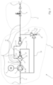
- Fig. 2 shows the start valve 22 in a start mode.
- the value of the volume flow through the start valve 22 corresponds to at least the resting volume threshold value.
- the value of the volume flow of the liquid through the start valve 22 is smaller than a start volume threshold value.
- the start volume threshold value is larger than the resting volume threshold value.
- the start valve 22 is designed such that it allows the flow of liquid from the pressure chamber 10 into the return line 12 when the volume flow through the start valve 22 is below the start volume threshold value.
- the start valve 22 has a Fig. 4 illustrated valve seat 35.
- a flow of liquid from the pressure chamber 10 of the main line 5 into the return line 12 is prevented.
- the valve member 27 In start mode, the valve member 27 is in a position in which it rests neither on the stop element 17 nor on the valve seat 35.
- the start valve 22 divides the pressure chamber 10 of the main line 5 into a pump section 14 and an ejection section 15.
- the pump section 14 of the pressure chamber 10 of the main line 5 extends from the high-pressure pump 2 to the start valve 22.
- the ejection section 15 of the pressure chamber 10 of the main line 5 extends from the start valve 22 to the ejection opening 6.
- liquid can flow through the start valve 22 both from the pump section 14 into the ejection section 15 and from the pump section 14 into the return line 12.
- the size of the volume flow that determines the position of the valve member 27 in the start valve 22 is almost unaffected by the partial branching of the volume flow into the return line 12 that only occurs after the valve member 27.
- the size of the volume flow that determines the position of the valve member 27 in the start valve 22 is almost unaffected by the partial division of the volume flow that only occurs after the valve member 27 into a portion of the volume flow that flows into the ejection section 15 and a further portion of the volume flow that flows into the return line.
- the start valve 22 has an inlet 23.
- the inlet 23 of the start valve 22 is connected to the main line 5.
- the inlet 23 of the start valve 22 is connected to the pump section 14 of the pressure chamber 10 of the main line 5.
- the start valve 22 has a return outlet 25.
- the return outlet 25 of the start valve 22 is connected to the return line 12.
- the start valve 22 has a main line outlet 26.
- the main line outlet 26 is connected to the main line 5.
- the main line outlet 26 is connected to the injection section 15 of the pressure chamber 10 of the main line 5.
- the return line 12 has an inlet 13.
- the valve seat 35 of the start valve 22 is arranged at the inlet 13 of the return line 12.
- the inlet 13 of the return line 12 coincides with the return outlet 25 of the start valve 22.
- fluid can flow from the inlet 23 of the start valve 22 to both the return outlet 25 and the main line outlet 26.
- the start valve 22 is designed such that it allows a direct flow of liquid from the pump section 14 into the ejection section 15 if the value of the volume flow through the start valve 22 corresponds at least to the start volume threshold value.
- the closing mode a loss-free flow of liquid from the pump section 14 into the ejection section 15 through the start valve 22 is possible.
- the liquid flows directly from the inlet 23 of the start valve 22 to the main line outlet 26 of the start valve 22.
- the liquid pumped by the high-pressure pump 3 flows directly from the pump section 14 into the ejection section 15 without a detour via the return line 12.
- the closing mode of the start valve 22 is also referred to as the operating mode.
- the high-pressure cleaning device 1 comprises a check valve 24.
- the check valve 24 is arranged in the pressure chamber 10.
- the check valve 24 is arranged downstream of the high-pressure pump 3.
- the check valve 24 is arranged downstream of the start valve 22.
- the check valve 24 is arranged upstream of the shut-off device 7 in the pressure chamber 10.
- the start valve 22 is arranged in the main line 5 between the high-pressure pump 3 and the check valve 24. Because the shut-off device 7 is arranged between the check valve 24 and the main line valve 8, the pressure on the shut-off device 7 can only rise and not fall as long as the motor 4 for driving the high-pressure pump 3 is running and the main line valve 8 is in the closed state.
- the direction of movement 49 extends in the longitudinal direction of the start valve 22.
- the valve member 27 is movable in the flow direction 50 to close the valve seat 35 of the start valve 22. By moving the valve member 27 in In the flow direction 50, the valve seat 35 arranged at the inlet 13 of the return line 12 can be closed.
- the valve member 27 is pre-tensioned in the direction away from the inlet 13 of the return line 12.
- the valve member 27 is pre-tensioned against the direction of movement 49.
- a spring 37 pre-tensions the valve member 27 in the direction away from the return line 12.
- the spring 37 is supported in the area of the valve seat 35 of the start valve 22.
- the spring 37 is arranged between the valve seat 35 and the valve member 27.
- the valve member 27 In the rest mode of the start valve 22, the valve member 27 is located on the Fig. 4
- the stop element 17 limits a movement of the valve member 27 in the direction away from the return line 12.
- the stop element 17 limits a movement of the valve member 27 in the direction opposite to the flow direction 50.
- the stop element 17 limits a movement of the valve member 27 in the direction opposite to the direction of movement 49.
- the valve member 27 has an inflow surface 28 on its end face facing away from the return line 12.
- the inflow surface 28 is aligned transversely, in the exemplary embodiment perpendicular to the flow direction 50.
- the stop element 17 protrudes in the flow direction 50 over a base body 38 of the housing 36 of the start valve 22.
- the stop element 17 prevents the inflow surface 28 of the valve member 27 from fully abutting against the housing 36 of the start valve 22.
- the stop element 17 has an outer contour.
- the outer contour of the stop element 17 delimits a stop surface running perpendicular to the flow direction 50.
- the stop surface is only a fraction of the inflow surface 28.
- the stop surface is formed by the surface of several stop elements. In the exemplary embodiment, the entire stop surface is less than 20%, in particular less than 10% of the outflow surface 28.
- a gap is formed between the base body 38 and the valve member 27 in the rest mode of the start valve 22. The stop element 17 ensures this.
- the start valve 22 has an inlet surface 29.
- the inlet surface 29 runs perpendicular to the flow direction 50.
- the liquid enters the start valve 22 through the inlet surface 29.
- the liquid enters the interior of the housing 36 of the start valve 22 through the inlet surface 29.
- the valve member 27 allows a minimum free cross-sectional area 30 through the main line 5.
- the minimum free cross-sectional area 30 is the area that the start valve 22 always makes available as a minimum flow area for the liquid.
- the smallest flow area for the liquid in the start valve 22 corresponds to the minimum free cross-sectional area 30.
- the valve member 27 has a circumferential surface 32 facing an inner wall of the start valve 22.
- a gap 33 is formed between the circumferential surface 32 and the inner wall 31.
- the gap 33 forms the minimum free cross-sectional area 30.
- the circumferential surface 32 has a plurality of recesses 34 distributed over the circumference.
- the recesses 34 are depressions in the circumferential surface 32.
- the circumferential surface 32 has a smallest gap distance s measured perpendicular to the inner wall 31 of the start valve 22.
- the smallest gap distance s is measured in the direction radial to the longitudinal axis of the start valve 22.
- the smallest gap distance s is measured in the exemplary embodiment in the direction radial to the direction of movement 49 of the valve member 27.
- the recesses 34 have a largest gap distance a measured perpendicular to the inner wall 31 of the start valve 22.
- the largest gap distance a is radial to the longitudinal axis of the Start valve 22.
- the largest recess distance a is measured radially to the direction of movement 49 of the valve member 27.
- the largest recess distance a is at least twice the smallest gap distance s. It can also be provided that the largest recess distance a is at least three times the smallest gap distance s. In the exemplary embodiment, the largest recess distance a is at least four times the smallest gap distance s.
- the largest recess distance a is at most 20 times the smallest gap distance s.
- the largest recess distance a is at most 18 times, in the exemplary embodiment at most 16 times the smallest gap distance s.
- At least two recesses 34, in particular at least four recesses, in the exemplary embodiment six recesses 34 are provided. The recesses 34 are distributed in the circumferential direction around the direction of movement 49 of the valve member 27, in particular evenly, in the circumferential surface 32 of the valve member 27.
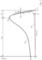
- Fig. 5 shows the torque-speed characteristic curve of an asynchronous motor.
- the speed n is plotted on the x-axis and the torque M on the y-axis.
- the characteristic curve 104 is shown with a solid line.
- the operating range 101 extends between a breakdown frequency assigned to the breakdown moment m kipp and the synchronous frequency n synchron . In order to reach this operating range, the asynchronous motor must run up.
- the speed range in which this run-up takes place is identified with the reference symbol 100.
- the corresponding speed range is referred to as the run-up range 100.
- the run-up range 100 is below the operating range 101.
- the run-up range 100 is directly adjacent to the operating range 101.
- the start valve 22 Due to the start valve 22 according to the invention, only a small load is applied during the run-up phase 100.
- the high-pressure pump 3 or the motor 4 does not have to work against a large pressure.
- the required torque against which the motor 4 works is shown with a dashed load line 105.
- the start valve 22 is initially in idle mode when the motor 4 is switched on. This state of the start valve 22 is in Fig. 1 Due to the volume flow generated during the start-up phase 100, the valve member 27 moves away from the stop element 17 into the start mode. This start mode is in Fig. 2
- the liquid delivered by the pump 3 can flow from the pressure chamber 10 through the start valve 22 into the return line 12 and back into the suction chamber 9.
- the load curve would already rise steeply in a range below the breakdown speed, which is assigned to the breakdown torque M breakdown .
- the required torque which is shown by the load curve 105, would exceed the available torque, which is shown by the characteristic curve 104.
- the result would be overheating of the motor 4 and stalling of the motor 4.
- the speed of the motor 4 would decrease and the available torque would also decrease, as can be seen from the characteristic curve 104 to the left of the breakdown speed. At some point the motor 4 would stop.
- the start valve 22 according to the invention reliably ensures that the start valve 22 only switches when the speed n of the engine 4 is in the operating range 101.
Landscapes
- Engineering & Computer Science (AREA)
- General Engineering & Computer Science (AREA)
- Mechanical Engineering (AREA)
- Safety Valves (AREA)
- Details Of Reciprocating Pumps (AREA)
Abstract
Die Erfindung betrifft ein Hochdruckreinigungsgerät umfassend einen Anschluss für eine Flüssigkeitsquelle, eine Hochdruckpumpe (3) und eine Hauptleitung (5), durch die mittels der Hochdruckpumpe (3) Flüssigkeit von dem Anschluss (2) zu einer Ausspritzöffnung (6) der Hauptleitung (5) förderbar ist. Die Hauptleitung (5) weist zwischen dem Anschluss (2) und der Hochdruckpumpe (3) einen Saugraum (9) auf. Die Hauptleitung (5) weist zwischen der Hochdruckpumpe (3) und der Ausspritzöffnung (6) einen Druckraum (10) auf. Der Druckraum (10) ist mit dem Saugraum (9) fluidisch über eine Rückführleitung (12) verbunden. Das Hochdruckreinigungsgerät (1) umfasst ein Startventil (22). Das Hochdruckreinigungsgerät (1) ist so ausgelegt, dass das Startventil (22) so schließt, dass durch die Rückführleitung (12) keine Flüssigkeit von dem Druckraum (10) in den Saugraum (9) fließen kann, wenn der Volumenstrom durch das Startventil (22) mindestens einem Startvolumenschwellwert entspricht. Das Startventil (22) ist in der Hauptleitung (5) stromabwärts der Hochdruckpumpe (3) angeordnet.
Description
- Die Erfindung betrifft ein Hochdruckreinigungsgerät nach dem Oberbegriff des Anspruchs 1.
- Es ist bekannt, dass zwischen dem Druckraum und dem Saugraum eine Rückführleitung mit einem Startventil vorgesehen sein kann. Das Hochdruckreinigungsgerät ist dabei so ausgelegt, dass das Startventil so schließt, dass durch die Rückführleitung keine Flüssigkeit von dem Druckraum in den Saugraum fließen kann, wenn der Volumenstrom durch das Startventil mindestens einem Startvolumenschwellwert entspricht. Unterhalb des Startvolumenschwellwerts ist jedoch ein Durchfluss von Flüssigkeit durch die Rückführleitung möglich. Dies erleichtert das Anlaufen der Hochdruckpumpe, bzw. des Motors der Hochdruckpumpe. Die Hochdruckpumpe muss insbesondere bei geschlossenem Hauptleitungsventil dann nicht gegen einen großen Druck im Druckraum arbeiten. Die Hochdruckpumpe kann in der Anlaufphase Flüssigkeit über die Rückführleitung vom Druckraum in den Saugraum im Kreis pumpen, ohne dass sie mit anfänglich geringem Drehmoment bzw. geringer Drehzahl gegen einen großen Gegendruck arbeiten muss. So kann die Pumpe bis zum Erreichen des Startvolumenschwellwerts und dem Schließen des Startventils eine Drehzahl erreichen, bei der sie dann bei entsprechendem Gegendruck ein ausreichendes Drehmoment zu Verfügung stellen kann. Erst nachdem die Hochdruckpumpe bzw. der Motor diese Drehzahl erreicht hat, muss sie bzw. er gegen einen größeren Druck im Druckraum anarbeiten. Bei Hochdruckreinigungsgeräten aus dem Stand der Technik kann es vorkommen, dass der Motor trotz des Startventils bei einem Anlaufversuch heiß läuft und ausgeht.
- Der Erfindung liegt die Aufgabe zugrunde, ein gattungsgemäßes Hochdruckreinigungsgerät derart weiterzubilden, dass ein zuverlässiges Anlaufen des Motors der Hochdruckpumpe gewährleistet ist.
- Diese Aufgabe wird durch ein Hochdruckreinigungsgerät mit den Merkmalen des Anspruchs 1 gelöst.
- Der Erfindung liegt die Erkenntnis zugrunde, dass der Zeitpunkt, bzw. der Drehzahlwert, bei dem das Startventil aufgrund des Erreichens des Startvolumenschwellwerts schließt, bei den bisher bekannten Hochdruckreinigungsgeräten bei weitgehend unveränderten Betriebsbedingungen nicht immer verlässlich reproduzierbar ist. In den Fällen, in denen der Motor heiß läuft und aus geht, wird das Startventil geschlossen, bevor der Motor eine Drehzahl in seinem Arbeitsbereich erreicht hat.
- Der Erfindung liegt weiterhin die Erkenntnis zugrunde, dass bei den Hochdruckreinigungsgeräten aus dem Stand der Technik der Volumenstrom in der Rückführleitung auch von externen Parametern wie dem Düsenquerschnitt an der Ausspritzöffnung und sonstigen Drosselungen in der Hauptleitung abhängt. Die Rückführleitung ist eine Abzweigungsleitung der Hauptleitung zwischen der Hochdruckpumpe und der Ausspritzöffnung. An dieser Abzweigung wird der Volumenstrom geteilt. Welcher Anteil des Volumenstroms vor der Abzweigung in die Rückleitung abgezweigt wird, ist abhängig von äußeren Parametern. Dies erklärt, warum bei ansonsten gleichbleibenden Betriebsbedingungen die Schließ- und Öffnungszeitpunkte des in der Rückführleitung angeordneten Startventils, bzw. die Drehzahlwerte des Motors, bei denen das Startventil öffnet oder schließt, variieren.
- Zur Lösung des im Rahmen der Erfindung erkannten Problems sieht die Erfindung vor, das Startventil in der Hauptleitung stromabwärts der Hochdruckpumpe anzuordnen. Durch die Anordnung des Startventils in der Hauptleitung trifft der volle, ungeteilte Volumenstrom der Flüssigkeit auf das Startventil. Da kein Anteil des Volumenstroms aus der Hauptleitung abgezweigt wurde, bevor der Volumenstrom auf das Startventil trifft, schließt und öffnet das Startventil zuverlässig. Der Parameter, der über das Schließen und Öffnen des Startventils entscheidet, ist bei der Erfindung zuverlässig reproduzierbar. Da der auf das Startventil treffende Volumenstrom ungeteilt ist, spielen äußere Parameter, die einen Einfluss darauf haben, wie große der abgezweigte Anteil an Volumenstrom in die Rückführleitung ist, keine Rolle. Insbesondere ist der Volumenstrom am Startventil unabhängig vom Düsenquerschnitt der an der Ausspritzöffnung eingesetzten Düse. Daher sind auch die Zeitpunkte bzw. die Drehzahlen des Motors, bei denen das Startventil öffnet und schließt, reproduzierbar. Dies hat zur Folge, dass auch der Druck, gegen den die Hochdruckpumpe beim Anlaufen anarbeiten muss, reproduzierbar ist. Durch die Anordnung des Startventils in der Hauptleitung kann das Startventil zuverlässig und reproduzierbar arbeiten. Dementsprechend schließt das Startventil zuverlässig erst dann, wenn der Motor beim Anlaufen eine Drehzahl in seinem Arbeitsdrehzahlbereich erreicht hat.
- Vorteilhaft ist das Startventil stromaufwärts der Rückführleitung in der Hauptleitung angeordnet. Dadurch ist sichergestellt, dass kein Anteil des Volumenstroms vor dem Auftreffen des Volumenstroms auf das Startventil in die Rückführleitung abgezweigt wird. Dadurch ergeben sich reproduzierbare Bedingungen für das Startventil. Zur Schaltung des Startventils steht der volle Volumenstrom zur Verfügung.
- Insbesondere ist das Startventil außerhalb der Rückführleitung angeordnet. Dadurch ist ein Abzweigen eines Anteils des Volumenstroms durch die Hauptleitung in die Rückführleitung vor dem Auftreffen auf das Startventil verhindert.
- Insbesondere ist die Hauptleitung im Bereich zwischen Hochdruckpumpe und Ausspritzöffnung diejenige Leitung des Hochdruckreinigungsgeräts, in der die Flüssigkeit von der Hochdruckpumpe zu der Ausspritzöffnung den kürzesten Weg zurücklegt. Abzweigungen von der Hauptleitung, in denen die Flüssigkeit möglicherweise vor- und zurückfließt, zählen nicht zu der Hauptleitung. Das Hochdruckreinigungsgerät besitzt einen Hauptströmungspfad. Entlang des Hauptströmungspfads strömt die Flüssigkeit vom Anschluss für die Flüssigkeitsquelle zu der Ausspritzöffnung. Der Hauptströmungspfad verläuft entlang der Hauptleitung. Das Startventil ist insbesondere im Hauptströmungspfad angeordnet.
- Zweckmäßig ist das Hochdruckreinigungsgerät so ausgelegt, dass die Flüssigkeit bei Betrieb des Hochdruckreinigungsgeräts mit einem Volumenstrom durch das Startventil unterhalb des Startvolumenschwellwerts ohne Abzweigungsmöglichkeit von der Hochdruckpumpe zu dem Startventil in der Hauptleitung fließt. Insbesondere ist das Hochdruckreinigungsgerät so ausgelegt, dass die Flüssigkeit bei Betrieb des Hochdruckreinigungsgeräts unabhängig vom Volumenstrom durch das Startventil ohne Abzweigungsmöglichkeit von der Hochdruckpumpe zu dem Startventil in der Hauptleitung fließt.
- Zweckmäßig ist das Startventil so ausgelegt, dass es bei einem Volumenstrom durch das Startventil unterhalb des Startvolumenschwellwerts den Durchfluss von Flüssigkeit von dem Druckraum in die Rückführleitung zulässt. Dies ermöglicht ein leichtes Anlaufen der Hochdruckpumpe bzw. des Motors der Hochdruckpumpe. Die Hochdruckpumpe bzw. der Motor muss während des Anlaufens gegen keinen großen Druck im Druckraum anarbeiten. Dies ist insbesondere bei geschlossenem Hauptleitungsventil von Vorteil.
- Zweckmäßig ist das Startventil so ausgelegt, dass es den Durchfluss von Flüssigkeit von dem Druckraum in die Rückführleitung unterbindet, wenn der Volumenstrom durch das Startventil mindestens dem Startvolumenschwellwert entspricht. Dadurch kann sich nach Erreichen des Startvolumenschwellwerts ein ausreichender Druck im Druckraum aufbauen. Die Reinigung mit dem Hochdruckreinigungsgerät ist dann möglich. Dadurch, dass das Startventil erst nach Erreichen des Startvolumenschwellwerts den Durchfluss von Flüssigkeit von dem Druckraum in die Rückführleitung unterbindet, kann der Motor der Hochdruckpumpe zunächst eine ausreichende Drehzahl erreichen, bei der er ein ausreichendes Drehmoment erzeugen kann, um gegen einen entsprechenden Druck im Druckraum anzuarbeiten. Dies verhindert Ausfälle des Motors und der Hochdruckpumpe während des Anlaufens. Ebenso ist verhindert, dass der Motor überhaupt nicht die ausreichende Drehzahl erreicht, weil der Druck, gegen den die Pumpe bzw. der Motor anarbeiten muss, zu groß ist.
- Insbesondere teilt das in der Hauptleitung sitzende Startventil den Druckraum der Hauptleitung in einen Pumpenabschnitt und einen Ausspritzabschnitt. Der Pumpenabschnitt ist zwischen der Hochdruckpumpe und dem Startventil angeordnet. Der Ausspritzabschnitt ist zwischen dem Startventil und der Ausspritzöffnung angeordnet. Vorteilhaft ist das Startventil so ausgelegt, dass es bei einem Volumenstrom durch das Startventil, der mindestens dem Startvolumenschwellwert entspricht, einen direkten Durchfluss von Flüssigkeit von dem Pumpenabschnitt in den Ausspritzabschnitt zulässt. Insbesondere erfolgt dieser direkte Durchfluss von dem Pumpenabschnitt in den Ausspritzabschnitt ohne den Umweg über die Rückführleitung. Insbesondere erfolgt der Übergang der Flüssigkeit von dem Pumpenabschnitt in den Ausspritzabschnitt ohne Abzweigen eines Anteils des Volumenstroms, beispielsweise in die Rückführleitung. Dadurch ist der von der Hochdruckpumpe im Druckraum erzeugte Druck unabhängig von dem Anteil des Volumenstroms, der in eine Rückführleitung abgezweigt wird. Dies trägt zu reproduzierbaren Betriebsbedingungen bei.
- Das Startventil besitzt einen Eingang. Der Eingang ist insbesondere mit der Hauptleitung verbunden. Der Eingang ist zweckmäßig unmittelbar mit der Hauptleitung verbunden. Der Eingang ist insbesondere mit dem Pumpenabschnitt des Druckraums der Hauptleitung verbunden. Das Startventil besitzt einen Rückführausgang. Der Rückführausgang ist insbesondere mit der Rückführleitung verbunden. Zweckmäßig besitzt das Startventil einen Hauptleitungsausgang. Der Hauptleitungsausgang ist insbesondere mit der Hauptleitung verbunden. Insbesondere ist der Hauptleitungsausgang mit dem Ausspritzabschnitt des Druckraums der Hauptleitung verbunden. Das Hochdruckreinigungsgerät ist zweckmäßig so ausgelegt, dass das Startventil den Rückführausgang schließt, wenn der Volumenstrom durch das Startventil mindestens dem Startvolumenschwellwert entspricht.
- Das Startventil besitzt ein Ventilglied. Die mittels der Hochdruckpumpe von dem Anschluss zu der Ausspritzöffnung durch die Hauptleitung geförderte Flüssigkeit trifft in der Hauptleitung in einer Strömungsrichtung auf das Startventil. Insbesondere ist das Hochdruckreinigungsgerät so gestaltet, dass die Strömungsrichtung im Auftreffpunkt der Flüssigkeit auf das Startventil parallel zur Hauptleitung verläuft.
- In vorteilhafter Weiterbildung der Erfindung umfasst das Hochdruckreinigungsgerät ein Anschlagelement für das Ventilglied. Zweckmäßig ist das Ventilglied in Richtung auf das Anschlagelement vorgespannt. Das Hochdruckreinigungsgerät ist so ausgelegt, dass das Ventilglied bei Unterschreiten eines Ruhevolumenschwellwerts des Volumenstroms durch das Startventil an dem Anschlagelement anliegt. Dadurch wird das Ventilglied mit definiertem Druck gegen das Anschlagelement gedrückt. Insbesondere bei Verwendung einer Feder zur Vorspannung des Ventilglieds herrschen bei Anlage des Ventilglieds an dem Anschlagelement definierte Kräfteverhältnisse. Insbesondere liegt das Ventilglied in einem durch die Flüssigkeit unbelasteten Zustand des Ventilglieds an dem Anschlagelement an. Aufgrund des Anschlagelements und des Anliegens des Ventilglieds am Anschlagelement ist der Druck, der durch den Volumenstrom für eine Bewegung des Ventilglieds weg von dem Anschlagelement aufgebracht werden muss, klar definiert. Dies trägt zu reproduzierbaren Arbeitsbedingungen des Hochdruckreinigungsgeräts bei.
- Zweckmäßig besitzt das Ventilglied eine Anströmfläche. Die Anströmfläche ist vorteilhaft quer, insbesondere senkrecht zur Strömungsrichtung ausgerichtet. Dadurch erfolgt eine besonders gute Kraft- bzw. Druckübertragung durch die Flüssigkeit auf das Ventilglied. Zweckmäßig ist die Anströmfläche des Ventilglieds vollständig in der Hauptleitung angeordnet.
- Insbesondere ist das Ventilglied in einer Bewegungsrichtung beweglich. Zweckmäßig verläuft die Bewegungsrichtung in Richtung der Strömungsrichtung. Auch dies trägt zu einer guten Druckübertragung von der Flüssigkeit auf das Ventilglied bei. Es kann vorgesehen sein, dass die Bewegungsrichtung des Ventilglieds in Richtung einer Axialrichtung des Startventils verläuft. Insbesondere verläuft die Axialrichtung des Startventils in Längsrichtung des Startventils.
- Vorteilhaft ist das Ventilglied vollständig in der Hauptleitung, insbesondere vollständig außerhalb der Rückführleitung, angeordnet.
- Das Ventilglied besitzt eine zu einer Innenwand des Startventils zeigende Umfangsfläche. Zweckmäßig ist zwischen der Umfangsfläche und der Innenwand ein Spalt ausgebildet, der eine minimale freie Querschnittsfläche bildet. Die minimale freie Querschnittsfläche ist die kleinste Fläche, durch die der Volumenstrom im Startventil strömt. Die minimale freie Querschnittsfläche muss nicht zwangsläufig senkrecht zur Hauptleitung verlaufen. Sie steht aber senkrecht auf die am Ort der minimalen freien Querschnittsfläche vorliegende Strömungsrichtung des Volumenstroms durch das Startventil.
- In vorteilhafter Weiterbildung der Erfindung weist das Startventil eine Eingangsfläche auf. Die Eingangsfläche ist senkrecht zur Strömungsrichtung orientiert. Durch die Eingangsfläche tritt die Flüssigkeit in das Startventil ein. Zweckmäßig lässt das Ventilglied unterhalb des Ruhevolumenschwellwerts, insbesondere in dem durch die Flüssigkeit unbelasteten Zustand, die minimale freie Querschnittsfläche durch die Hauptleitung zu. Zweckmäßig beträgt die minimale freie Querschnittsfläche mindestens 5%, bevorzugt mindestens 10% der Eingangsfläche. Dadurch ist ein Durchfluss von Flüssigkeit durch das Startventil auch unterhalb des Ruhevolumenschwellwerts, insbesondere in dem durch die Flüssigkeit unbelasteten Zustand, möglich. Dadurch, dass das Startventil unterhalb des Ruhevolumenschwellwerts die Hauptleitung nicht verschließt, lässt sich das Ventilglied leicht aus seiner Ruheposition bewegen. Beim bzw. nach dem Anlaufen der Hochdruckpumpe bzw. des Motors kann das Ventilglied dann leicht aus seiner Ruheposition, insbesondere von dem Anschlagelement weggedrückt werden. Ein Anhaften oder Festsaugen des Ventilglieds ist dadurch verhindert.
- Bevorzugt beträgt die minimale freie Querschnittsfläche höchstens 70%, insbesondere höchstens 60% der Eingangsfläche. Dadurch kann genug Druck von der Flüssigkeit auf das Ventilglied wirken. Das Ventilglied lässt sich leicht aus seiner Ruheposition bewegen.
- In besonderer Ausgestaltung der Erfindung besitzt die Umfangsfläche über den Umfang verteilt mehrere Aussparungen. Die Umfangsfläche besitzt einen senkrecht zur Innenwand des Startventils gemessenen kleinsten Spaltabstand. Die Aussparungen besitzen zur Innenwand einen senkrecht zur Innenwand des Startventils gemessenen größten Aussparungsabstand. Der größte Aussparungsabstand beträgt zweckmäßig mindestens das Doppelte des kleinsten Spaltabstands. Durch die Einbringung von Aussparungen kann das Ventilglied auf einfache Weise an verschiedene Einsatzbedingungen angepasst werden. Fertigungstechnisch müssen hierzu lediglich unterschiedliche Anzahlen an Aussparungen eingebracht werden. Insbesondere beträgt der größte Aussparungsabstand der Aussparungen höchstens das 20fache des kleinsten Spaltabstands.
- Vorteilhaft ist das Ventilglied zum Verschließen eines Ventilsitzes des Startventils in Strömungsrichtung beweglich. Zweckmäßig ist der Ventilsitz an einem Eingang der Rückführleitung angeordnet.
- Ein Ausführungsbespiel der Erfindung wird im Folgenden anhand der Zeichnung erläutert. Es zeigen:
- Fig. 1
- eine schematische Darstellung eines Hochdruckreinigungsgeräts in einem Betriebszustand, in dem die Hochdruckpumpe keine Flüssigkeit fördert und die Rückführleitung nicht vom Starventil verschlossen ist,
- Fig. 2
- eine schematische Darstellung eines Hochdruckreinigungsgeräts aus
Fig. 1 in einem Betriebszustand, in dem die Hochdruckpumpe Flüssigkeit derart fördert, dass der Volumenstrom der durch das Startventil geförderten Flüssigkeit unterhalb des Startvolumenschwellwerts liegt, - Fig. 3
- eine schematische Darstellung des Hochdruckreinigungsgeräts aus
Fig. 1 in einem Betriebszustand, in dem die Hochdruckpumpe Flüssigkeit mit einem Volumenstrom durch das Startventil oberhalb des Startvolumenschwellwerts fördert, so dass das Startventil die Rückführleitung verschließt, - Fig. 4
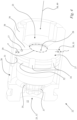
- eine halbgeschnittene, schematische Darstellung des Startventils aus den
Fig. 1 bis 3 und - Fig. 5
- ein schematisches Diagramm, das die Abhängigkeit des verfügbaren und des erforderlichen Drehmoments des Motors zum Antrieb der Hochdruckpumpe von der Drehzahl zeigt.
-
Fig. 1 zeigt in schematischer Darstellung ein Hochdruckreinigungsgerät 1. Das Hochdruckreinigungsgerät 1 umfasst eine Pumpeneinheit 16 und eine Ausspritzeinheit 11. Die Pumpeneinheit 16 und die Ausspritzeinheit 11 sind über eine Hauptleitung 5 fluidisch miteinander verbunden. Die Ausspritzeinheit 11 umfasst im Ausführungsbeispiel eine nicht dargestellte Pistole. Es kann aber auch vorgesehen sein, dass die Ausspritzeinheit eine Pistole und eine Lanze umfasst. - Das Hochdruckreinigungsgerät 1 umfasst einen Anschluss 2 für eine Flüssigkeitsquelle. Im Ausführungsbeispiel ist die Flüssigkeitsquelle eine externe Flüssigkeitsquelle. Die externe Flüssigkeitsquelle kann beispielsweise ein Hauswassernetz sein. Es kann aber auch vorgesehen sein, dass die Flüssigkeitsquelle integraler Bestandteil des Hochdruckreinigungsgeräts ist.
- Das Hochdruckreinigungsgerät 1 umfasst eine Ausspritzöffnung 6. Das Hochdruckreinigungsgerät 1 umfasst die Hauptleitung 5. Die Hauptleitung 5 des Hochdruckreinigungsgeräts 1 verbindet den Anschluss 2 mit der Ausspritzöffnung 6 fluidisch. Der Anschluss 2 ist an der Pumpeneinheit 16 angeordnet. Die Ausspritzöffnung 6 ist an der Ausspritzeinheit 11 angeordnet. Im Ausführungsbeispiel ist die Ausspritzöffnung 6 an der als Pistole ausgebildeten Ausspritzeinheit 11 angeordnet. Es kann aber auch vorgesehen sein, dass die Ausspritzöffnung 6 an einer austauschbaren Lanze der Ausspritzeinheit 11 angeordnet ist.
- Das Hochdruckreinigungsgerät 1 umfasst eine Hochdruckpumpe 3. Mittels der Hochdruckpumpe 3 ist durch die Hauptleitung 5 Flüssigkeit von dem Anschluss 2 zu der Ausspritzöffnung 6 förderbar. Die Flüssigkeitsquelle führt der Hauptleitung 5 Flüssigkeit zu. Die Hochdruckpumpe 3 ist in der Hauptleitung 5 angeordnet. Die Hochdruckpumpe 3 setzt die Flüssigkeit unter Druck. Die Hauptleitung 5 besitzt einen Saugraum 9 und einen Druckraum 10. Die Hochdruckpumpe 3 ist zwischen dem Saugraum 9 und dem Druckraum 10 der Hauptleitung 5 angeordnet. Die Hauptleitung 5 weist den Saugraum 9 zwischen dem Anschluss 2 und dem Hochdruckpumpe 3 auf. Die Hauptleitung 5 weist den Druckraum 10 zwischen der Hochdruckpumpe 3 und der Ausspritzöffnung 6 auf. Im Ausführungsbeispiel ist der Saugraum 9 durch einen Abschnitt der Hauptleitung 5 zwischen dem Anschluss 2 und der Hochdruckpumpe 3 gebildet. Im Ausführungsbeispiel ist der Druckraum 10 durch einen Abschnitt der Hauptleitung 5 zwischen der Hochdruckpumpe 3 und der Ausspritzöffnung 6 gebildet. Die Hochdruckpumpe 3 fördert Flüssigkeit vom Saugraum 9 zu dem Druckraum 10. Im Druckraum 10 herrscht insbesondere im Betrieb der Hochdruckpumpe 3 ein größerer Druck als in dem Saugraum 9. Der Saugraum 9 und der Druckraum 10 sind Bestandteile der Hauptleitung 5. Stromab der Hochdruckpumpe 3 herrscht im Betrieb der Hochdruckpumpe 3 ein größerer Druck in der Hauptleitung 5 als stromauf der Hochdruckpumpe 3.
- Die Hochdruckpumpe 3 ist in der Pumpeneinheit 16 angeordnet. Zum Antrieb der Hochdruckpumpe 3 weist das Hochdruckreinigungsgerät 1 einen Motor 4 auf. Der Motor 4 ist in der Pumpeneinheit 16 angeordnet. Der Motor 4 kann als bürstenloser Gleichstrommotor ausgebildet sein. Ein bürstenloser Gleichstrommotor wird auch als EC-Motor bezeichnet. Bei dem Motor 4 kann es sich auch um einen Universalmotor handeln. Im Ausführungsbeispiel ist der Motor 4 ein Induktionsmotor. Der Induktionsmotor im Ausführungsbeispiel wird mit Wechselspannung betrieben. Die Spannungsquelle kann beispielsweise durch die Netzspannung zur Verfügung gestellt sein. Falls ein Batterie- oder Akkubetrieb vorgesehen ist, kann es sich bei dem Motor auch um einen bürstenlosen Gleichstrommotor handeln. Es kann vorgesehen sein, dass der Akku Bestandteil des Hochdruckreinigungsgeräts 1 ist.
- Das Hochdruckreinigungsgerät 1 umfasst ein Hauptleitungsventil 8. Das Hauptleitungsventil 8 ist in der Hauptleitung 5 angeordnet. Das Hauptleitungsventil 8 weist zwei Ventilzustände auf. Die zwei Ventilzustände umfassen einen geschlossenen Zustand und einen offenen Zustand. Im offenen Zustand lässt das Hauptleitungsventil 8 einen Durchfluss von Flüssigkeit durch die Hauptleitung 5 zu. In dem geschlossenen Zustand unterbindet das Hauptleitungsventil 8 einen Durchfluss von Flüssigkeit durch die Hauptleitung 5. Im offenen Zustand des Hauptleitungsventils 8 wird Flüssigkeit aus der Ausspritzöffnung 6 herausgespritzt. Im geschlossenen Zustand des Hauptleitungsventils 8 wird keine Flüssigkeit aus der Ausspritzöffnung 6 herausgespritzt. Im Ausführungsbeispiel ist das Hauptleitungsventil 8 in der Ausspritzeinheit 11 angeordnet. Im Ausführungsbeispiel ist das Hauptleitungsventil 8 zwischen der Hochdruckpumpe 3 und der Ausspritzöffnung 6 angeordnet.
- Das Hochdruckreinigungsgerät 1 umfasst eine Abschalteinrichtung 7. Das Hochdruckreinigungsgerät 1 ist so ausgelegt, dass die Abschalteinrichtung 7 aufgrund des im Druckraum 10 vorliegenden Drucks bewirkt, dass sich der Motor 4 im Aus-Zustand befindet, wenn der Druck im Druckraum mindestens einem Druckschwellwert entspricht.
- Der Motor 4 weist einen Schalter 18 auf. Der Schalter 18 dient zur Schaltung des Motors 4 zwischen dem An-Zustand und dem Aus-Zustand. Die Abschalteinrichtung 7 weist ein Betätigungselement 19 auf. Das Hochdruckreinigungsgerät 1 ist so ausgelegt, dass die Flüssigkeit im Druckraum 10 so auf das Betätigungselement 19 der Abschalteinrichtung 7 wirkt, dass das Betätigungselement 19 den Schalter 18 des Motors 4 so betätigt, dass sich der Motor 4 im Aus-Zustand befindet, wenn der Druck im Druckraum 10 mindestens dem Druckschwellwert entspricht.
- In
Fig. 1 ist eine Druckentlastungsleitung 20 dargestellt. Die Druckentlastungsleitung 20 verbindet den Druckraum 10 fluidisch mit dem Saugraum 9. Durch die Druckentlastungsleitung 20 ist eine weitere fluidische Verbindung von Saugraum 9 und Druckraum 10 separat von der fluidischen Verbindung des Saugraums 9 mit dem Druckraum 10 über die Hochdruckpumpe 3 möglich. - Die Druckentlastungsleitung 20 kann geschlossen oder geöffnet sein. In der Druckentlastungsleitung 20 ist ein Druckentlastungsventil 21 angeordnet. Das Druckentlastungsventil 21 ist so ausgelegt, dass es öffnet, wenn der Druck im Druckraum 10 mindestens dem Druckschwellwert entspricht.
- Das Hochdruckreinigungsgerät 1 ist so ausgelegt, dass zwischen dem Druckraum 10 und dem Saugraum 9 eine fluidische Verbindung besteht, wenn der Druck im Druckraum 10 höchstens einem Startdruckwert entspricht. Der Startdruckwert ist kleiner als der Druckschwellwert. Das Hochdruckreinigungsgerät 1 weist im Ausführungsbeispiel eine Rückführleitung 12 auf. Die Rückführleitung 12 kann den Druckraum 10 fluidisch mit dem Saugraum 9 verbinden. Durch die Rückführleitung 12 ist eine weitere fluidische Verbindung von Saugraum 9 und Druckraum 10 separat von der fluidischen Verbindung des Saugraums 9 mit dem Druckraum 10 über die Hochdruckpumpe 3 und separat von der Druckentlastungsleitung 20 möglich.
- Das Hochdruckreinigungsgerät 1 umfasst ein Startventil 22. Das Hochdruckreinigungsgerät 1 ist so ausgelegt, dass das Startventil 22 bei Erreichen oder Überschreiten eines Startvolumenschwellwerts des Volumenstroms durch das Startventil 22 das Startventil 22 schließt. Insbesondere entspricht der Druck im Druckraum 10 bei Erreichen oder Überschreiten des Startvolumenschwellwerts des Volumenstroms durch das Startventil 22 mindestens dem Startdruckwert. Bei geschlossenem Startventil 22 kann durch die Rückführleitung 12 keine Flüssigkeit von dem Druckraum 10 in den Saugraum 9 fließen. Wie in
Fig. 1 dargestellt, ist das Startventil 22 in der Hauptleitung 5 angeordnet. Das Startventil 22 ist stromabwärts der Hochdruckpumpe 3 in der Hauptleitung 5 angeordnet. Das Startventil 22 ist stromaufwärts der Rückführleitung 12 in der Hauptleitung 5 angeordnet. Von der Hochdruckpumpe 3 geförderte Flüssigkeit trifft zuerst auf das Startventil 22, bevor sie in die Rückführleitung 12 vordringen kann. Das Startventil 22 ist außerhalb der Rückführleitung 12 angeordnet. - Die Hauptleitung 5 ist diejenige Leitung des Hochdruckreinigungsgeräts 1 im Bereich zwischen der Hochdruckpumpe 3 und der Ausspritzöffnung 6, in der die Flüssigkeit von der Hochdruckpumpe 3 zu der Ausspritzöffnung 6 den kürzesten Weg zurücklegt. Abzweigungen von der Hauptleitung 5, in denen Flüssigkeit möglicherweise zuerst in die Abzweigung vordringt und dann wieder zurückfließt, sind nicht Bestandteil der Hauptleitung 5.
- Das Hochdruckreinigungsgerät 1 ist so ausgelegt, dass die Flüssigkeit bei Betrieb des Hochdruckreinigungsgeräts 1 mit einem Volumenstrom durch das Startventil 22 unterhalb des Startvolumenschwellwerts ohne Abzweigungsmöglichkeit von der Hochdruckpumpe 3 zu dem Startventil 22 in der Hauptleitung 5 fließt. Insbesondere fließt die Flüssigkeit bei Betrieb des Hochdruckreinigungsgeräts 1 unabhängig vom Volumenstrom durch das Startventil 22 ohne Abzweigungsmöglichkeit von der Hochdruckpumpe 3 zu dem Startventil 22 in der Hauptleitung 5.
- Das Startventil 22 besitzt im Wesentlichen drei Zustände. Die Zustände des Startventils 1 sind durch den Wert des Volumenstroms durch das Startventil 22 bestimmt. Ist der Wert des Volumenstroms der Flüssigkeit durch das Startventil 22 kleiner als ein Ruhevolumenschwellwert, befindet sich das Startventil 22 in einem Ruhemodus. Der Ruhemodus des Startventils 22 ist in
Fig. 1 dargestellt. Im Ruhemodus reicht der von der Flüssigkeit auf das Startventil 22 ausgeübte Druck nicht aus, um das Startventil 22 in einen anderen Zustand zu überführen. Das Startventil 22 besitzt ein Ventilglied 27. Das Ventilglied 27 ist in die Ruhestellung des Ruhemodus vorgespannt. Es kann vorgesehen sein, dass das Ventilglied 27 hierbei einen Ventilsitz der Hauptleitung verschließt, so dass ein Durchfluss von Flüssigkeit durch die Hauptleitung 5 von dem Ventilglied 27 unterbunden ist. Im Ausführungsbeispiel weist das Startventil 22 jedoch ein Anschlagelement 17 auf. In der Ruhestellung liegt das Ventilglied 27 an dem Anschlagelement 17 an. Das Ventilglied 27 ist in Richtung auf das Anschlagelement 17 vorgespannt. Wenn der Volumenstrom durch das Startventil 22 kleiner als der Ruhevolumenschwellwert ist, liegt das Ventilglied 27 an dem Anschlagelement 17 an. Insbesondere liegt das Ventilglied 27 an dem Anschlagelement 17 an, wenn sich das Ventilglied 27 in einem durch die Flüssigkeit unbelasteten Zustand befindet. Im Ausführungsbeispiel ist das Startventil 22 so ausgelegt, dass im Ruhemodus ein Durchtritt von Flüssigkeit durch das Startventil 22 möglich ist. Hierfür ist bei Anlage des Ventilglieds 27 an dem Anschlagelement 17 ein Spalt zwischen dem Ventilglied 27 und dem Ventilgehäuse vorgesehen. -
Fig. 2 zeigt das Startventil 22 in einem Startmodus. Im Startmodus wird Flüssigkeit durch das Startventil 22 hindurch von dem Druckraum 10 der Hauptleitung 5 über die Rückführleitung 12 zurück in den Saugraum 9 gefördert. Der Wert des Volumenstroms durch das Startventil 22 entspricht im Startmodus des Startventils 22 mindestens dem Ruhevolumenschwellwert. Der Wert des Volumenstroms der Flüssigkeit durch das Startventil 22 ist im Startmodus kleiner als ein Startvolumenschwellwert. Der Startvolumenschwellwert ist größer als der Ruhevolumenschwellwert. Im Ausführungsbeispiel ist das Startventil 22 so ausgelegt, dass es bei einem Volumenstrom durch das Startventil 22 unterhalb des Startvolumenschwellwerts den Durchfluss von Flüssigkeit von dem Druckraum 10 in die Rückführleitung 12 zulässt. - Das Startventil 22 besitzt einen in
Fig. 4 dargestellten Ventilsitz 35. Wenn das Ventilglied 27 am Ventilsitz 35 anliegt, ist ein Durchfluss von Flüssigkeit aus dem Druckraum 10 der Hauptleitung 5 in die Rückführleitung 12 unterbunden. Im Startmodus befindet sich das Ventilglied 27 in einer Stellung, in der es weder an dem Anschlagelement 17 noch an dem Ventilsitz 35 anliegt. - Das Startventil 22 teilt den Druckraum 10 der Hauptleitung 5 in einen Pumpenabschnitt 14 und einen Ausspritzabschnitt 15. Der Pumpenabschnitt 14 des Druckraums 10 der Hauptleitung 5 erstreckt sich von der Hochdruckpumpe 2 bis zu dem Startventil 22. Der Ausspritzabschnitt 15 des Druckraums 10 der Hauptleitung 5 erstreckt sich von dem Startventil 22 bis zu der Ausspritzöffnung 6. Im Startmodus des Startventils 22 kann Flüssigkeit durch das Startventil 22 sowohl von dem Pumpenabschnitt 14 in den Ausspritzabschnitt 15 als auch von dem Pumpenabschnitt 14 in die Rückführleitung 12 fließen. Die Größe des Volumenstroms, der die Stellung des Ventilglieds 27 in dem Startventil 22 bestimmt, ist nahezu unbeeinflusst von der erst nach dem Ventilglied 27 auftretenden teilweisen Abzweigung des Volumenstroms in die Rückführleitung 12. Die Größe des Volumenstroms, der die Stellung des Ventilglieds 27 in dem Startventil 22 bestimmt, ist nahezu unbeeinflusst von der erst nach dem Ventilglied 27 auftretenden teilweisen Aufteilung des Volumenstroms in einen Anteil des Volumenstroms, der in den Ausspritzabschnitt 15 fließt und einen weiteren Anteil des Volumenstroms, der in die Rückführleitung fließt.
- Das Startventil 22 besitzt einen Eingang 23. Der Eingang 23 des Startventils 22 ist mit der Hauptleitung 5 verbunden. Der Eingang 23 des Startventils 22 ist mit dem Pumpenabschnitt 14 des Druckraums 10 der Hauptleitung 5 verbunden. Das Startventil 22 besitzt einen Rückführausgang 25. Der Rückführausgang 25 des Startventils 22 ist mit der Rückführleitung 12 verbunden. Das Startventil 22 besitzt einen Hauptleitungsausgang 26. Der Hauptleitungsausgang 26 ist mit der Hauptleitung 5 verbunden. Der Hauptleitungsausgang 26 ist mit dem Ausspritzabschnitt 15 des Druckraums 10 der Hauptleitung 5 verbunden. Die Rückführleitung 12 besitzt einen Eingang 13. Der Ventilsitz 35 des Startventils 22 ist an dem Eingang 13 der Rückführleitung 12 angeordnet. Der Eingang 13 der Rückführleitung 12 fällt mit dem Rückführausgang 25 des Startventils 22 zusammen.
- Im Startmodus des Startventils 22 kann Flüssigkeit von dem Eingang 23 des Startventils 22 sowohl zu dem Rückführausgang 25 als auch zu dem Hauptleitungsausgang 26 fließen.
-
Fig. 3 zeigt das Startventil 22 in einem Schließmodus. Das Startventil 22 ist so ausgelegt, dass es bei einem Volumenstrom durch das Startventil 22, der mindestens dem Startvolumenschwellwert entspricht, den Durchfluss von Flüssigkeit von dem Druckraum 10 in die Rückführleitung 12 unterbindet. Wenn der Wert des Volumenstroms durch das Startventil mindestens dem Startvolumenschwellwert entspricht, schließt das Startventil 22 den Rückführausgang 25. - Das Startventil 22 ist so ausgelegt, dass es einen direkten Durchfluss von Flüssigkeit von dem Pumpenabschnitt 14 in den Ausspritzabschnitt 15 zulässt, wenn der Wert des Volumenstroms durch das Startventil 22 mindestens dem Startvolumenschwellwert entspricht. Insbesondere ist im Schließmodus ein verlustfreier Durchfluss von Flüssigkeit von dem Pumpenabschnitt 14 in den Ausspritzabschnitt 15 durch das Startventil 22 hindurch möglich. Im Schließmodus des Startventils 22 fließt die Flüssigkeit direkt vom Eingang 23 des Startventils 22 zu dem Hauptleitungsausgang 26 des Startventils 22. Im Schließmodus des Startventils 22 fließt die von der Hochdruckpumpe 3 geförderte Flüssigkeit unmittelbar von dem Pumpenabschnitt 14 in den Ausspritzabschnitt 15 ohne einen Umweg über die Rückführleitung 12. Der Schließmodus des Startventils 22 wird auch als Betriebsmodus bezeichnet.
- Wie in den
Fig. 1 bis 3 dargestellt, umfasst das Hochdruckreinigungsgerät 1 ein Rückschlagventil 24. Das Rückschlagventil 24 ist im Druckraum 10 angeordnet. Das Rückschlagventil 24 ist stromabwärts der Hochdruckpumpe 3 angeordnet. Das Rückschlagventil 24 ist stromabwärts des Startventils 22 angeordnet. Das Rückschlagventil 24 ist stromaufwärts der Abschalteinrichtung 7 im Druckraum 10 angeordnet. Das Startventil 22 ist in der Hauptleitung 5 zwischen der Hochdruckpumpe 3 und dem Rückschlagventil 24 angeordnet. Dadurch, dass die Abschalteinrichtung 7 zwischen dem Rückschlagventil 24 und dem Hauptleitungsventil 8 angeordnet ist, kann der Druck auf die Abschalteinrichtung 7, solange der Motor 4 zum Antrieb der Hochdruckpumpe 3 läuft und sich das Hautleitungsventil 8 im geschlossenen Zustand befindet, nur steigen und nicht fallen. Dies kann auch bewirken, dass der Druck auf das Druckentlastungsventil 21, solange der Motor 4 zum Antrieb der Hochdruckpumpe 3 läuft und sich das Hauptleitungsventil 8 im geschlossenen Zustand befindet, nur steigen kann. So ist sichergestellt, dass der Druck im Druckraum 10 den Druckschwellwert überschreitet und die Abschalteinrichtung 7 den Motor 4 in den Aus-Zustand überführt. Ebenfalls kann so sichergestellt sein, dass der Druck im Druckraum 10 den Druckschwellwert überschreitet und das Druckentlastungsventil 21 öffnet. -
Fig. 4 zeigt das Ventil 22 in teilgeschnittener Darstellung. Das Startventil 22 besitzt ein Ventilgehäuse 36. In dem Ventilgehäuse 36 ist das Ventilglied 27 angeordnet. Das Ventilglied 27 ist in dem Ventilgehäuse 36 in einer Bewegungsrichtung 49 beweglich. Die mittels der Hochdruckpumpe 3 von dem Anschluss 2 zu der Ausspritzöffnung 6 durch die Hauptleitung 5 geförderte Flüssigkeit trifft in der Hauptleitung 5 in einer Strömungsrichtung 50 auf das Startventil 22, insbesondere auf das Ventilglied 27 des Startventils 22. Die Strömungsrichtung 50 ist diejenige Richtung, in der die Flüssigkeit durch den Eingang 23 des Startventils 22 in das Startventil 22 hineinströmt. Die Bewegungsrichtung 49 des Ventilglieds 27 verläuft in Richtung der Strömungsrichtung 50. Die Bewegungsrichtung 49 verläuft entlang einer Bewegungsachse des Ventilglieds 27. Die Bewegungsrichtung 49 erstreckt sich in Längsrichtung des Startventils 22. Das Ventilglied 27 ist zum Verschließen des Ventilsitzes 35 des Startventils 22 in Strömungsrichtung 50 beweglich. Durch eine Bewegung des Ventilglieds 27 in Strömungsrichtung 50 kann der am Eingang 13 der Rückführleitung 12 angeordnete Ventilsitz 35 verschlossen werden. - Das Ventilglied 27 ist in Richtung weg von dem Eingang 13 der Rückführleitung 12 vorgespannt. Das Ventilglied 27 ist entgegen der Bewegungsrichtung 49 vorgespannt. Im Ausführungsbeispiel spannt eine Feder 37 das Ventilglied 27 in Richtung weg von der Rückführleitung 12 vor. Die Feder 37 stützt sich im Bereich des Ventilsitzes 35 des Startventils 22 ab. Die Feder 37 ist zwischen dem Ventilsitz 35 und dem Ventilglied 27 angeordnet. Das Ventilglied 27 liegt im Ruhemodus des Startventils 22 an dem in
Fig. 4 dargestellten Anschlagelement 17 an. Das Anschlagelement 17 begrenzt eine Bewegung des Ventilglieds 27 in Richtung weg von der Rückführleitung 12. Das Anschlagelement 17 begrenzt eine Bewegung des Ventilglieds 27 in Richtung entgegen der Strömungsrichtung 50. Das Anschlagelement 17 begrenzt eine Bewegung des Ventilglieds 27 in Richtung entgegen der Bewegungsrichtung 49. - Das Ventilglied 27 besitzt an seiner der Rückführleitung 12 abgewandten Stirnseite eine Anströmfläche 28. Die Anströmfläche 28 ist quer, im Ausführungsbeispiel senkrecht zur Strömungsrichtung 50 ausgerichtet. Das Anschlagelement 17 steht in Strömungsrichtung 50 über einen Grundkörper 38 des Gehäuses 36 des Startventils 22 hervor. Das Anschlagelement 17 verhindert eine vollflächige Anlage der Anströmfläche 28 des Ventilglieds 27 am Gehäuse 36 des Startventils 22. In Strömungsrichtung 50 gesehen besitzt das Anschlagelement 17 eine Außenkontur. Die Außenkontur des Anschlagelements 17 begrenzt eine senkrecht zur Strömungsrichtung 50 verlaufende Anschlagfläche. Die Anschlagfläche beträgt nur einen Bruchteil der Anströmfläche 28. Die Anschlagfläche ist im Ausführungsbeispiel durch die Fläche mehrerer Anschlagelemente gebildet. Im Ausführungsbeispiel beträgt die gesamte Anschlagfläche weniger als 20%, insbesondere weniger als 10% der Ausströmfläche 28. Zwischen dem Grundkörper 38 und dem Ventilglied 27 ist im Ruhemodus des Startventils 22 ein Spalt ausgebildet. Hierfür sorgt das Anschlagelement 17.
- Das Startventil 22 besitzt eine Eingangsfläche 29. Die Eingangsfläche 29 verläuft senkrecht zur Strömungsrichtung 50. Durch die Eingangsfläche 29 tritt die Flüssigkeit in das Startventil 22 ein. Durch die Eingangsfläche 29 tritt die Flüssigkeit in das Innere des Gehäuses 36 des Startventils 22 ein. Im Ruhemodus des Startventils 22 lässt das Ventilglied 27 eine minimale freie Querschnittsfläche 30 durch die Hauptleitung 5 zu. Die minimale freie Querschnittsfläche 30 ist die Fläche, die das Startventil 22 immer mindestens als Durchströmungsfläche für die Flüssigkeit zur Verfügung stellt. Im Ruhemodus des Startventils 22 entspricht die kleinste Durchströmungsfläche für die Flüssigkeit im Startventil 22 der minimalen freien Querschnittsfläche 30.
- Im Ruhemodus des Startventils 22 befindet sich das Ventilglied 27 in einem durch die Flüssigkeit unbelasteten Zustand. Im Ruhemodus beträgt die minimale freie Querschnittsfläche 30 mindestens 5%, im Ausführungsbeispiel mindestens 10% der Eingangsfläche 29. Die minimale freie Querschnittsfläche 30 beträgt höchstens 70%, im Ausführungsbeispiel höchstens 60% der Eingangsfläche 29.
- Das Ventilglied 27 besitzt eine zu einer Innenwand des Startventils 22 zeigende Umfangsfläche 32. Zwischen der Umfangsfläche 32 und der Innenwand 31 ist ein Spalt 33 ausgebildet. Der Spalt 33 bildet die minimale freie Querschnittsfläche 30.
- Wie in
Fig. 4 dargestellt, besitzt die Umfangsfläche 32 über den Umfang verteilte mehrere Aussparungen 34. Die Aussparungen 34 sind Vertiefungen in der Umfangsfläche 32. Die Umfangsfläche 32 besitzt zur Innenwand 31 des Startventils 22 einen senkrecht zur Innenwand 31 gemessenen kleinsten Spaltabstand s. Der kleinste Spaltabstand s ist in Richtung radial zur Längsachse des Startventils 22 gemessen. Der kleinste Spaltabstand s ist im Ausführungsbeispiel in Richtung radial zur Bewegungsrichtung 49 des Ventilglieds 27 gemessen. Die Aussparungen 34 besitzen zur Innenwand 31 des Startventils 22 einen senkrecht zur Innenwand 31 des Startventils 22 gemessenen größten Aussparungsabstand a. Der größte Aussparungsabstand a ist radial zur Längsachse des Startventils 22 gemessen. Der größte Aussparungsabstand a ist radial zur Bewegungsrichtung 49 des Ventilglieds 27 gemessen. Der größte Aussparungsabstand a beträgt mindestens das Doppelte des kleinsten Spaltabstands s. Es kann auch vorgesehen sein, dass der größte Aussparungsabstand a mindestens das Dreifache des kleinsten Spaltabstands s beträgt. Im Ausführungsbeispiel beträgt der größte Aussparungsabstand a mindestens das Vierfache des kleinsten Spaltabstands s. Der größte Aussparungsabstand a beträgt höchstens das 20fache des kleinsten Spaltabstands s. Der größte Aussparungsabstand a beträgt höchstens das 18fache, im Ausführungsbeispiel höchstens das 16fache des kleinsten Spaltabstands s. Es sind mindestens zwei Aussparungen 34, insbesondere mindestens vier Aussparungen, im Ausführungsbeispiel sechs Aussparungen 34 vorgesehen. Die Aussparungen 34 sind in Umfangsrichtung um die Bewegungsrichtung 49 des Ventilglieds 27, insbesondere gleichmäßig, in der Umfangsfläche 32 des Ventilglieds 27 verteilt. -
Fig. 5 zeigt die Drehmoment-Drehzahl-Kennlinie eines Asynchronmotors. Auf der x-Achse ist die Drehzahl n aufgetragen und auf der y-Achse das Drehmoment M aufgetragen. Die Kennlinie 104 ist mit durchgezogener Linie eingezeichnet. Der Arbeitsbereich 101 erstreckt sich zwischen einer dem Kippmoment mkipp zugeordneten Kippfrequenz und der Synchronfrequenz nsynchron. Um in diesen Arbeitsbereich zu gelangen, muss der Asynchronmotor hochlaufen. Der Drehzahlbereich, in dem dieser Hochlauf stattfindet, ist mit dem Bezugszeichen 100 gekennzeichnet. Der entsprechende Drehzahlbereich wird als Hochlaufbereich 100 bezeichnet. Der Hochlaufbereich 100 liegt unterhalb des Arbeitsbereichs 101. Der Hochlaufbereich 100 grenzt unmittelbar an den Arbeitsbereich 101 an. - Aufgrund des erfindungsgemäßen Startventils 22 liegt während der Hochlaufphase 100 lediglich eine geringe Last an. Die Hochdruckpumpe 3 bzw. der Motor 4 muss gegen keinen großen Druck anarbeiten. Das erforderliche Drehmoment, gegen das der Motor 4 anarbeitet, ist mit gestrichelter Lastlinie 105 eingezeichnet. Das Startventil 22 ist beim Einschalten des Motors 4 zunächst im Ruhemodus. Dieser Zustand des Startventils 22 ist in
Fig. 1 dargestellt. Aufgrund des dann während der Hochlaufphase 100 erzeugten Volumenstroms bewegt sich das Ventilglied 27 von dem Anschlagelement 17 weg in den Startmodus. Dieser Startmodus ist inFig. 2 dargestellt. Die von der Pumpe 3 geförderte Flüssigkeit kann aus dem Druckraum 10 durch das Startventil 22 hindurch in die Rückführleitung 12 und zurück in den Saugraum 9 strömen. Hierfür ist kein großes Drehmoment erforderlich, wie die Lastkennlinie 105 im Bereich der Hochlaufphase 100 inFig. 5 zeigt. Unproblematisch kann der Motor 4 den Hochlaufbereich 100 durchlaufen und eine Drehzahl im Arbeitsbereich 101 erreichen. Aufgrund des erfindungsgemäßen Startventils ist sichergestellt, dass das Startventil erst dann in den inFig. 3 dargestellten Schließmodus übergeht, wenn sich die Drehzahl nach dem Hochlaufen des Motors 4 im Arbeitsbereich 101 des Motors 4 befindet. Erst dann schließt das Startventil 22, so dass keine Flüssigkeit mehr durch die Rückführleitung 12 von dem Druckraum 10 in den Saugraum 9 fließen kann. Anschließend liegt an der Pumpe 3 eine viel größere Last an, wie auch der steile Anstieg der Lastkurve 105 im Arbeitsbereich 101 inFig. 5 zeigt. Die Drehzahl kann anschließend auf die Drehzahl am Arbeitspunkt 102 einpendeln. - Wenn das Startventil 22 bereits bei einer Drehzahl außerhalb des Betriebsbereichs 101 - bei eine Drehzahl im Hochlaufbereich 100 - schließen würde, würde die Lastkurve bereits in einem Bereich unterhalb der Kippdrehzahl, die dem Kippdrehmoment MKipp zugeordnet ist, steil ansteigen. Das erforderliche Drehmoment, das durch die Lastkurve 105 eingezeichnet ist, würde das verfügbare Drehmoment, das durch die Kennlinie 104 eingezeichnet ist, übersteigen. Die Folge wäre eine Überhitzung des Motors 4 und ein Abwürgen des Motors 4. Die Drehzahl des Motors 4 würde abnehmen und das zu Verfügung stehende Drehmoment ebenfalls, wie der Kennlinie 104 links der Kippdrehzahl zu entnehmen ist. Irgendwann würde der Motor 4 stehen bleiben.
- Durch das erfindungsgemäße Startventil 22 ist zuverlässig sichergestellt, dass das Startventil 22 erst schaltet, wenn sich die Drehzahl n des Motors 4 im Betriebsbereich 101 befindet.
- Die in
Fig. 5 dargestellte Drehmomentkennlinie ist die eines Asynchronmotors. Die Beschreibung trifft aber auch auf andere Motortypen in analoger Weise zu. - Insbesondere nach einem Abschalten des Motors 4 durch Betätigung des in den
Fig. 1 bis 3 dargestellten Schalters 18 der Abschalteinrichtung 7 nach einem Schließen des Hauptleitungsventils 8 herrscht im Druckraum 10 ein großer Druck. Dieser Druck wird teilweise durch Öffnen des Druckventils 21 abgebaut. Durch diesen Druckabbau öffnet das Startventil 22, so dass ein Rückfluss von Flüssigkeit aus dem Druckraum 10, insbesondere aus dem Pumpenabschnitt 14 des Druckraums 10 in den Saugraum 9 möglich ist. Das Startventil 22 befindet sich dann entweder im Ruhemodus oder im Startmodus. Bei einem Wiedereinschalten des Motors 4 muss die Pumpe 3 aufgrund des geöffneten Startventils 22 gegen einen viel geringeren Druck anarbeiten, als wenn das Startventil 22 nicht vorhanden wäre. Aufgrund der Anordnung des Startventils 22 in der Hauptleitung 5 ist der Volumenstrom, der ein Schalten des Startventils 22 bewirkt, klar definiert.
Claims (15)
- Hochdruckreinigungsgerät umfassend:- einen Anschluss (2) für eine Flüssigkeitsquelle,- eine Hochdruckpumpe (3) und- eine Hauptleitung (5), durch die mittels der Hochdruckpumpe (3) Flüssigkeit von dem Anschluss (2) zu einer Ausspritzöffnung (6) der Hauptleitung (5) förderbar ist,wobei die Hauptleitung (5) zwischen dem Anschluss (2) und der Hochdruckpumpe (3) einen Saugraum (9) aufweist, wobei die Hauptleitung (5) zwischen der Hochdruckpumpe (3) und der Ausspritzöffnung (6) einen Druckraum (10) aufweist, wobei der Druckraum (10) mit dem Saugraum (9) fluidisch über eine Rückführleitung (12) verbunden ist, wobei das Hochdruckreinigungsgerät (1) ein Startventil (22) umfasst, und wobei das Hochdruckreinigungsgerät (1) so ausgelegt ist, dass das Startventil (22) so schließt, dass durch die Rückführleitung (12) keine Flüssigkeit von dem Druckraum (10) in den Saugraum (9) fließen kann, wenn der Volumenstrom durch das Startventil (22) mindestens einem Startvolumenschwellwert entspricht,dadurch gekennzeichnet, dass das Startventil (22) in der Hauptleitung (5) stromabwärts der Hochdruckpumpe (3) angeordnet ist.
- Hochdruckreinigungsgerät nach Anspruch 1,
dadurch gekennzeichnet, dass das Startventil (22) stromaufwärts der Rückführleitung (12) in der Hauptleitung (5) angeordnet ist. - Hochdruckreinigungsgerät nach Anspruch 1 oder 2,
dadurch gekennzeichnet, dass das Startventil (22) außerhalb der Rückführleitung (12) angeordnet ist. - Hochdruckreinigungsgerät nach einem der Ansprüche 1 bis 3,
dadurch gekennzeichnet, dass das Hochdruckreinigungsgerät (1) so ausgelegt ist, dass die Flüssigkeit bei Betrieb des Hochdruckreinigungsgeräts (1) mit einem Volumenstrom durch das Startventil (22) unterhalb des Startvolumenschwellwerts, insbesondere unabhängig vom Volumenstrom durch das Startventil (22), ohne Abzweigungsmöglichkeit von der Hochdruckpumpe (3) zu dem Startventil (22) in der Hauptleitung (5) fließt. - Hochdruckreinigungsgerät nach einem der Ansprüche 1 bis 4,
dadurch gekennzeichnet, dass das Startventil (22) so ausgelegt ist, dass es bei einem Volumenstrom durch das Startventil (22) unterhalb des Startvolumenschwellwerts den Durchfluss von Flüssigkeit von dem Druckraum (10) in die Rückführleitung (12) zulässt, und insbesondere dass das Startventil (22) so ausgelegt ist, dass es den Durchfluss von Flüssigkeit von dem Druckraum (10) in die Rückführleitung (12) unterbindet, wenn der Volumenstrom durch das Startventil (22) mindestens dem Startvolumenschwellwert entspricht. - Hochdruckreinigungsgerät nach einem der Ansprüche 1 bis 5,
dadurch gekennzeichnet, dass das Startventil (22) den Druckraum (10) der Hauptleitung (5) in einen Pumpenabschnitt (14) und einen Ausspritzabschnitt (15) teilt, dass der Pumpenabschnitt (14) zwischen der Hochdruckpumpe (2) und dem Startventil (22) angeordnet ist, dass der Ausspritzabschnitt (15) zwischen dem Startventil (22) und der Ausspritzöffnung (6) angeordnet ist, und dass das Startventil (22) so ausgelegt ist, dass es einen direkten Durchfluss von Flüssigkeit von dem Pumpenabschnitt (14) in den Ausspritzabschnitt (15) zulässt, wenn der Volumenstrom durch das Startventil (22) mindestens dem Startvolumenschwellwert entspricht. - Hochdruckreinigungsgerät nach einem der Ansprüche 1 bis 6,
dadurch gekennzeichnet, dass das Startventil (22) einen Eingang (23) besitzt, der mit der Hauptleitung (5) verbunden ist, dass das Startventil (22) einen Rückführausgang (25) besitzt, der mit der Rückführleitung (12) verbunden ist, und dass das Startventil (22) einen Hauptleitungsausgang (26) besitzt, der mit der Hauptleitung (5) verbunden ist. - Hochdruckreinigungsgerät nach Anspruch 7,
dadurch gekennzeichnet, dass das Startventil (22) den Rückführausgang (25) schließt, wenn der Volumenstrom durch das Startventil (22) mindestens dem Startvolumenschwellwert entspricht. - Hochdruckreinigungsgerät nach einem der Ansprüche 1 bis 8,
dadurch gekennzeichnet, dass das Startventil (22) ein Ventilglied (27) besitzt, und dass die mittels der Hochdruckpumpe (3) von dem Anschluss (2) zu der Ausspritzöffnung (6) durch die Hauptleitung (5) geförderte Flüssigkeit in der Hauptleitung (5) in einer Strömungsrichtung (50) auf das Startventil (22) trifft. - Hochdruckreinigungsgerät nach Anspruch 9,
dadurch gekennzeichnet, dass das Ventilglied (27) in einer Bewegungsrichtung (49) beweglich ist, und dass die Bewegungsrichtung (49) in Richtung der Strömungsrichtung (50) verläuft. - Hochdruckreinigungsgerät nach Anspruch 9 oder 10,
dadurch gekennzeichnet, dass das Hochdruckreinigungsgerät (1) ein Anschlagelement (17) für das Ventilglied (27) umfasst, dass das Ventilglied (27) in Richtung auf das Anschlagelement (17) vorgespannt ist, und dass das Ventilglied (27) bei Unterschreiten eines Ruhevolumenschwellwerts des Volumenstroms durch das Startventil (22), insbesondere in einem durch die Flüssigkeit unbelasteten Zustand des Ventilglieds (27), an dem Anschlagelement (17) anliegt. - Hochdruckreinigungsgerät nach einem der Ansprüche 9 bis 11,
dadurch gekennzeichnet, dass das Startventil (22) senkrecht zur Strömungsrichtung (50) eine Eingangsfläche (29) aufweist, durch die die Flüssigkeit in das Startventil (22) eintritt, dass das Ventilglied (27) in einem durch die Flüssigkeit unbelasteten Zustand eine minimale freie Querschnittsfläche (30) durch die Hauptleitung (5) zulässt, und dass die minimale freie Querschnittsfläche (30) mindestens 5%, insbesondere mindestens 10% der Eingangsfläche (29) beträgt. - Hochdruckreinigungsgerät nach Anspruch 11 oder 12,
dadurch gekennzeichnet, dass das Ventilglied (27) eine zu einer Innenwand (31) des Startventils (22) zeigende Umfangsfläche (32) besitzt, dass zwischen der Umfangsfläche (32) und der Innenwand (31) ein Spalt (33) ausgebildet ist, der die minimale freie Querschnittsfläche (30) bildet. - Hochdruckreinigungsgerät nach Anspruch 13,
dadurch gekennzeichnet, dass die Umfangsfläche (32) über den Umfang verteilt mehrere Aussparungen (34) besitzt, dass die Umfangsfläche (32) zur Innenwand (31) des Startventils (22) einen senkrecht zur Innenwand (31) des Startventils (22) gemessenen kleinsten Spaltabstand (s) besitzt, dass die Aussparungen (34) zur Innenwand (31) des Startventils (22) einen senkrecht zur Innenwand (31) des Startventils (22) gemessenen größten Aussparungsabstand (a) besitzen, und dass der größte Aussparungsabstand (a) mindestens das Doppelte des kleinsten Spaltabstands (s), und insbesondere höchstens das 20fache des kleinsten Spaltabstands (s), beträgt. - Hochdruckreinigungsgerät nach einem der Ansprüche 9 bis 14,
dadurch gekennzeichnet, dass das Ventilglied (27) zum Verschließen eines Ventilsitzes (35) des Startventils (22) in Strömungsrichtung (50) beweglich ist, und dass der Ventilsitz (35) an einem Eingang (13) der Rückführleitung (12) angeordnet ist.
Priority Applications (2)
| Application Number | Priority Date | Filing Date | Title |
|---|---|---|---|
| EP23180026.9A EP4480592A1 (de) | 2023-06-19 | 2023-06-19 | Hochdruckreinigungsgerät |
| US18/747,745 US20240416373A1 (en) | 2023-06-19 | 2024-06-19 | Pressure washer |
Applications Claiming Priority (1)
| Application Number | Priority Date | Filing Date | Title |
|---|---|---|---|
| EP23180026.9A EP4480592A1 (de) | 2023-06-19 | 2023-06-19 | Hochdruckreinigungsgerät |
Publications (1)
| Publication Number | Publication Date |
|---|---|
| EP4480592A1 true EP4480592A1 (de) | 2024-12-25 |
Family
ID=86904353
Family Applications (1)
| Application Number | Title | Priority Date | Filing Date |
|---|---|---|---|
| EP23180026.9A Pending EP4480592A1 (de) | 2023-06-19 | 2023-06-19 | Hochdruckreinigungsgerät |
Country Status (2)
| Country | Link |
|---|---|
| US (1) | US20240416373A1 (de) |
| EP (1) | EP4480592A1 (de) |
Citations (8)
| Publication number | Priority date | Publication date | Assignee | Title |
|---|---|---|---|---|
| EP0383029A2 (de) * | 1989-01-17 | 1990-08-22 | Shop-Vac Corporation | Hochdruckreiniger mit Bypass |
| EP0608796B1 (de) * | 1993-01-22 | 1997-06-11 | WAP Reinigungssysteme GmbH & Co. | Druck-Saugverteiler eines Hochdruckreinigungsgerätes mit zusätzlichem Steuerventil |
| US5718255A (en) * | 1997-01-09 | 1998-02-17 | Generac Corporation | Flow-responsive diverting valve |
| US6334458B1 (en) * | 1999-05-21 | 2002-01-01 | Arrow Line S.R.L. | By-pass valve in particular for pressure-washing machines |
| US20070031266A1 (en) * | 2005-07-22 | 2007-02-08 | Arrow Line S.R.L. | Self-closing valve with adjustable activation |
| EP1340911B1 (de) * | 2002-03-01 | 2010-01-20 | DeVilbiss Air Power Company | Pumpe und Hochdruckreiniger |
| US9115703B2 (en) * | 2012-01-25 | 2015-08-25 | Robert Bosch Gmbh | Adjustable hydraulic pump |
| EP3670912B1 (de) * | 2018-12-19 | 2021-07-14 | Tecomec S.r.l. | Druckregelndes bypass-ventil |
Family Cites Families (17)
| Publication number | Priority date | Publication date | Assignee | Title |
|---|---|---|---|---|
| US3140049A (en) * | 1962-11-28 | 1964-07-07 | Britt Tech Corp | Cleaning apparatus with relief control valve |
| US3522909A (en) * | 1968-06-26 | 1970-08-04 | Clayton Manufacturing Co | Instantaneous high-impact fluid jet cleaning systems |
| US3608824A (en) * | 1970-03-30 | 1971-09-28 | Lennawill Inc | High-pressure washing equipment |
| US3680786A (en) * | 1971-06-28 | 1972-08-01 | Chemtrust Ind Corp | Mobile cleaning apparatus |
| US3893591A (en) * | 1974-02-11 | 1975-07-08 | Britt Tech Corp | High pressure spray washing system |
| US4851724A (en) * | 1988-08-08 | 1989-07-25 | Power Flo Products Corp. | Pressure washer |
| US5035580A (en) * | 1989-09-14 | 1991-07-30 | Diversified Dynamics Corporation | Bypass mode control for high pressure washing system |
| US5749526A (en) * | 1995-08-28 | 1998-05-12 | Gary R. Laabs | Centrally installed cleaning/washing system for buildings |
| US5979788A (en) * | 1996-11-21 | 1999-11-09 | Northern Tool & Equipment Company, Inc. | Pressure washer valve assembly |
| US6275654B1 (en) * | 1998-12-21 | 2001-08-14 | E. Gerald Hebert | Cleaning unit |
| US10537671B2 (en) * | 2006-04-14 | 2020-01-21 | Deka Products Limited Partnership | Automated control mechanisms in a hemodialysis apparatus |
| US20100282862A1 (en) * | 2009-05-06 | 2010-11-11 | Briggs & Stratton Corporation | Pressure washer with throttle control |
| US8496188B2 (en) * | 2010-06-23 | 2013-07-30 | Karcher North America, Inc. | Pressure washer device employing a cool bypass |
| US20110315176A1 (en) * | 2010-06-23 | 2011-12-29 | Briggs & Stratton Corporation | Engine speed control for a pressure washer |
| US8814531B2 (en) * | 2012-08-02 | 2014-08-26 | Briggs & Stratton Corporation | Pressure washers including jet pumps |
| US8960565B2 (en) * | 2012-08-16 | 2015-02-24 | Pressure Washers Northwest, Llc | Apparatus for hot water pressure washer with an automatic burner cool-down |
| US12193623B2 (en) * | 2016-03-02 | 2025-01-14 | Z Intellectual Property Holding Company, Llc | Systems and methods for cleaning surfaces |
-
2023
- 2023-06-19 EP EP23180026.9A patent/EP4480592A1/de active Pending
-
2024
- 2024-06-19 US US18/747,745 patent/US20240416373A1/en active Pending
Patent Citations (8)
| Publication number | Priority date | Publication date | Assignee | Title |
|---|---|---|---|---|
| EP0383029A2 (de) * | 1989-01-17 | 1990-08-22 | Shop-Vac Corporation | Hochdruckreiniger mit Bypass |
| EP0608796B1 (de) * | 1993-01-22 | 1997-06-11 | WAP Reinigungssysteme GmbH & Co. | Druck-Saugverteiler eines Hochdruckreinigungsgerätes mit zusätzlichem Steuerventil |
| US5718255A (en) * | 1997-01-09 | 1998-02-17 | Generac Corporation | Flow-responsive diverting valve |
| US6334458B1 (en) * | 1999-05-21 | 2002-01-01 | Arrow Line S.R.L. | By-pass valve in particular for pressure-washing machines |
| EP1340911B1 (de) * | 2002-03-01 | 2010-01-20 | DeVilbiss Air Power Company | Pumpe und Hochdruckreiniger |
| US20070031266A1 (en) * | 2005-07-22 | 2007-02-08 | Arrow Line S.R.L. | Self-closing valve with adjustable activation |
| US9115703B2 (en) * | 2012-01-25 | 2015-08-25 | Robert Bosch Gmbh | Adjustable hydraulic pump |
| EP3670912B1 (de) * | 2018-12-19 | 2021-07-14 | Tecomec S.r.l. | Druckregelndes bypass-ventil |
Also Published As
| Publication number | Publication date |
|---|---|
| US20240416373A1 (en) | 2024-12-19 |
Similar Documents
| Publication | Publication Date | Title |
|---|---|---|
| DE3142604C2 (de) | ||
| EP2817516B1 (de) | Pumpe für ein hochdruckreinigungsgerät und hochdruckreinigungsgerät | |
| DE102015213936A1 (de) | Spüleinrichtung für hydrostatische Vorrichtung | |
| DE102015119095B4 (de) | Kühlmittelpumpe für eine Verbrennungskraftmaschine | |
| WO2016173800A1 (de) | Pumpenvorrichtung | |
| DE102012001369B4 (de) | Verstellbare Hydropumpe | |
| WO1993009349A1 (de) | Flügelzellenpumpe | |
| DE69712067T2 (de) | Fluidstrom steuerventil einer hydraulischen pumpe | |
| DE102023101418A1 (de) | Hochdruckreinigungsgerät | |
| DE202015103751U1 (de) | Pumpenvorrichtung | |
| DE102016108944B4 (de) | Verstellbare Flügelzellenpumpe | |
| EP3015708B1 (de) | Flügelzellenpumpe mit verbessertem startverhalten | |
| DE102007023858A1 (de) | Kühlmittelpumpe für einen Kühlkreislauf einer Brennkraftmaschine | |
| DE3800377C1 (en) | By-pass valve for a high-pressure cleaning appliance | |
| EP0793017B1 (de) | Pumpe für ein Hochdruckreinigungsgerät | |
| DE102011101641B4 (de) | Ventil und Pumpenanordnung mit einem derartigen Ventil | |
| DE102009060188A1 (de) | Verstellventil für die Verstellung des Fördervolumens einer Verdrängerpumpe mit Kaltstartfunktion | |
| DE19523533A1 (de) | Sauggeregelte Innenzahnradpumpe | |
| EP2623796B1 (de) | Ventilbaugruppe mit Vorsteuerpumpe | |
| DE102015104549A1 (de) | Dichtlinienoptimierte Exzenterschneckenpumpe | |
| DE102011082644A1 (de) | Pumpenanordnung für ein Kraftstoffeinspritzsystem sowie Kraftstoffeinspritzsystem | |
| DE19606070B4 (de) | Leistungslenkvorrichtung | |
| WO2013167371A2 (de) | Pumpeneinheit | |
| EP2711549B1 (de) | Steuervorrichtung für Pumpen bei Hochdruckreinigern | |
| EP0546459B1 (de) | Öldruckschalter |
Legal Events
| Date | Code | Title | Description |
|---|---|---|---|
| PUAI | Public reference made under article 153(3) epc to a published international application that has entered the european phase |
Free format text: ORIGINAL CODE: 0009012 |
|
| STAA | Information on the status of an ep patent application or granted ep patent |
Free format text: STATUS: THE APPLICATION HAS BEEN PUBLISHED |
|
| AK | Designated contracting states |
Kind code of ref document: A1 Designated state(s): AL AT BE BG CH CY CZ DE DK EE ES FI FR GB GR HR HU IE IS IT LI LT LU LV MC ME MK MT NL NO PL PT RO RS SE SI SK SM TR |
|
| STAA | Information on the status of an ep patent application or granted ep patent |
Free format text: STATUS: REQUEST FOR EXAMINATION WAS MADE |
|
| 17P | Request for examination filed |
Effective date: 20250625 |