EP4480547A1 - Inflatable fall protection pad featuring rollers - Google Patents
Inflatable fall protection pad featuring rollers Download PDFInfo
- Publication number
- EP4480547A1 EP4480547A1 EP24168600.5A EP24168600A EP4480547A1 EP 4480547 A1 EP4480547 A1 EP 4480547A1 EP 24168600 A EP24168600 A EP 24168600A EP 4480547 A1 EP4480547 A1 EP 4480547A1
- Authority
- EP
- European Patent Office
- Prior art keywords
- base wall
- inflatable
- roller units
- fall protection
- protection pad
- Prior art date
- Legal status (The legal status is an assumption and is not a legal conclusion. Google has not performed a legal analysis and makes no representation as to the accuracy of the status listed.)
- Pending
Links
Images



Classifications
-
- A—HUMAN NECESSITIES
- A62—LIFE-SAVING; FIRE-FIGHTING
- A62B—DEVICES, APPARATUS OR METHODS FOR LIFE-SAVING
- A62B5/00—Other devices for rescuing from fire
-
- A—HUMAN NECESSITIES
- A62—LIFE-SAVING; FIRE-FIGHTING
- A62B—DEVICES, APPARATUS OR METHODS FOR LIFE-SAVING
- A62B1/00—Devices for lowering persons from buildings or the like
- A62B1/22—Devices for lowering persons from buildings or the like by making use of jumping devices, e.g. jumping-sheets, jumping-mattresses
-
- A—HUMAN NECESSITIES
- A62—LIFE-SAVING; FIRE-FIGHTING
- A62B—DEVICES, APPARATUS OR METHODS FOR LIFE-SAVING
- A62B3/00—Devices or single parts for facilitating escape from buildings or the like, e.g. protection shields, protection screens; Portable devices for preventing smoke penetrating into distinct parts of buildings
-
- A—HUMAN NECESSITIES
- A63—SPORTS; GAMES; AMUSEMENTS
- A63B—APPARATUS FOR PHYSICAL TRAINING, GYMNASTICS, SWIMMING, CLIMBING, OR FENCING; BALL GAMES; TRAINING EQUIPMENT
- A63B6/00—Mats or the like for absorbing shocks for jumping, gymnastics or the like
- A63B6/02—Mats or the like for absorbing shocks for jumping, gymnastics or the like for landing, e.g. for pole vaulting
Definitions
- the subject matter of the present disclosure relates generally to fall protection pads for restraining falls by persons or objects, and more particularly to a mobile inflatable fall protection pad that feature rollers to assist in moving the pad over a ground surface.
- Manufacturing and maintenance environments involve personnel working on structures that can be in a partially assembled or disassembled state.
- mobile structures such as aircraft frames or other large machinery as well as stationary structures such as buildings can involve personnel working at heights from which a fall could cause injury.
- floors, walls, and railings may not be present, thereby providing locations where personnel could fall while performing manufacturing or maintenance tasks.
- An inflatable fall protection pad comprises a deformable body defining an inflatable three-dimensional volume.
- the deformable body has a base wall, an upper wall, and sidewalls spanning the base wall and the upper wall.
- the inflatable fall protection pad further comprises a set of roller units mounted to the base wall along an exterior-facing surface of the base wall.
- the set of roller units is arranged in a multi-dimensional array. Two or more roller units of the set are spaced apart from each other in a first dimension of the multi-dimensional array. Two or more roller units of the set are spaced apart from each other in a second dimension of the multi-dimensional array that is orthogonal to the first dimension.
- an inflatable fall protection pad comprises a deformable body defining an inflatable three-dimensional volume.
- the deformable body has a base wall, an upper wall, and sidewalls spanning the base wall and the upper wall.
- the inflatable fall protection pad further comprises a set of roller units mounted to the base wall along an exterior-facing surface of the base wall.
- the set of roller units is arranged in a multi-dimensional array. Two or more roller units of the set are spaced apart from each other in a first dimension of the multi-dimensional array. Two or more roller units of the set are spaced apart from each other in a second dimension of the multi-dimensional array that is orthogonal to the first dimension.
- the set of roller units of the inflatable fall protection pad enable the pad to be rolled over a ground surface.
- the pad can be of a mass, area, or volume that would otherwise be difficult for a person or group of people to move in the absence of the roller units due friction between the base wall and the ground surface.
- the deformable body of the pad when deflated, can be folded for storage along one or more folding paths located between the roller units in both the first dimension and the second dimension. Additionally or alternatively, the deformable body of the pad can be rolled for storage.
- a load applied to the upper wall can influence the mobility of the inflatable fall protection pad.
- the set of roller units are spaced apart from each other over an area defined by the base wall, deformation of the base wall upon application of a load to the upper wall can cause the base wall to deform toward the ground surface. Such deformation can cause the base wall to initiate or increase contact with the ground surface.
- one or more regions of the base wall located between the set of rollers can deform to contact the ground surface under a load applied to the upper wall, thereby increasing a lateral resistance to movement of the pad along the ground surface due to friction.
- Such deformation and increased contact between the base wall and the ground surface can provide a braking function having a braking force that is responsive to a load applied to the upper wall.
- the braking function can assist in stabilizing the pad.
- contact of the base wall with the ground surface can increase, thereby increasing the lateral resistance to movement of the pad along the ground surface.
- the set of roller units can be sized and arranged upon the base wall of the pad such that the base wall initiates contact with the ground surface responsive to a load being applied to the upper wall that attains or exceeds a predetermined magnitude.
- the base wall does not contact the ground surface when no load or a load that is less than the predetermined magnitude is applied to the upper wall of the pad.
- This approach can support mobility of the pad under conditions in which objects that do not attain or exceed the predetermined magnitude are supported by the upper wall of the pad.
- This approach also enables the braking function discussed above to be provided under select conditions in which a load applied to the upper wall attains or exceeds the predetermined magnitude.
- the predetermined magnitude of the load can be selected to correspond to the static weight of a sample human adult applied to the upper wall.
- a conservative weight estimate of an adult can be used, such as 100 pounds or other suitable value, as an illustrative example.
- the predetermined magnitude can be selected to correspond to the dynamic force of a human adult falling from a given distance.
- the predetermined magnitude of the load can be selected to correspond to the static weight or dynamic force of a child.
- FIG. 1 schematically depicts an example inflatable fall protection pad 100 in an inflated state.
- Pad 100 includes a deformable body 110 defining an inflatable three-dimensional volume 112.
- Body 110 has a base wall 120, an upper wall 122, and sidewalls 124A, 124B, 124C, 124D spanning the base wall and the upper wall.
- body 110 can be formed from a flexible textile material or flexible continuous sheet material.
- Such materials can include a polymer such as nylon, vinyl, Polyvinyl chloride (PVC) and/or natural fiber, as examples.
- Textile materials can be treated with a polymer coating in at least some examples to reduce air permeability and/or provide water resistance.
- pad 100 further comprises a set of roller units mounted to base wall 120.
- the set of roller units enable pad 100 to be rolled along a ground surface 130.
- body 110 of pad 100 is of a size, weight, or volume that would otherwise be difficult for a person or group of people to move in the absence of the set of roller units due to friction between base wall 120 and ground surface 130.
- FIG. 1 schematically depicts a person 132 in relation to body 110 of pad 100 to provide an example scale of body 110. It will be understood that body 110 can be of other suitable size and/or shape.
- upper wall 122 and base wall 120 have different areas, and sidewalls 124B and 124D taper between the base wall and the upper wall on opposite sides of body 110.
- upper wall 122 has a larger area than base wall 120, and sidewalls taper 124B and 124D taper inward from the upper wall to the base wall on opposite sides of body 110.
- Sidewalls 124B and 124D have respective profiles 144B and 144D that are shaped to accommodate a physical structure within or between which pad 100 can be used.
- the physical structure can include an interior of a fuselage of an aircraft, as described in further detail with reference to FIG. 3 . It will be understood that body 110 can be of other suitable shape.
- FIG. 1 schematically depicts an example fan assembly 150 that can be used to inflate body 110 and maintain body 110 in the inflated state.
- body 110 includes an opening 152 by which air is provided to inflate three-dimensional volume 112 defined by body 110.
- sidewall 124A defines opening 152.
- An outflow of fan assembly 150 can be fluidly coupled with opening 152 via a flexible or rigid conduit 154.
- conduit 154 can form part of body 110.
- an outflow of fan assembly 150 can be mounted directly to opening 152.
- fan assembly 150 can be mounted upon a set of rollers that enables the fan assembly to follow after pad 110 as the pad is moved between locations.
- conduit 154 also serves as a tether by which fan assembly 150 is mounted to body 110.
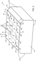
- FIG. 2 schematically depicts another view of inflatable fall protection pad 100 of FIG. 1 in the inflated state in which base wall 120 is visible.
- base wall 120 has a rectangular shape.
- base wall 120 can have a polygon shape of three, four, five or more sides.
- base wall can have a circular shape, oval shape, or irregular shape.
- Pad 100 includes a set of roller units 210 mounted to base wall 120 along an exterior-facing surface 220 of the base wall.
- the set of roller units 210 are arranged in a multi-dimensional array 230.
- Two or more roller units 212 of set 210 are spaced apart from each other in a first dimension 232 of multi-dimensional array 230, and two or more roller units 214 of the set 210 are spaced apart from each other in a second dimension 234 of multi-dimensional array 230 that is orthogonal to the first dimension.
- deformation of the base wall upon application of a load to upper wall 122 can initiate or increase contact of the base wall with the ground surface.
- one or more regions of base wall 120 surrounding and located between the set of roller units 210, such as example region 260 can deform to contact or increase contact with the ground surface under a load applied to upper wall 122, thereby increasing a lateral resistance to movement of the pad along the ground surface due to friction.
- Such deformation and increased contact between base wall 120 and the ground surface can provide a braking function having a braking force that is responsive to a load applied to the upper wall.
- exterior-facing surface 220 of base wall 120 comprises a different material than an exterior-facing surface of upper wall 122 and/or sidewalls.
- exterior-facing surface 220 of base wall 120 can comprise a material having a higher coefficient of friction as compared to a material of exterior-facing surface of upper wall 122 and/or the sidewalls to facilitate the braking function described herein, for example due to the material's composition, texture, and so forth.
- surface 220 can be made from such a material, or incorporate such a material, or be at least partially covered with such a material.
- the set of roller units 210 is arranged in two, three, four or more rows 240A, 240B, 240C, 240D, etc. of multi-dimensional array 230 in which each row includes two or more roller units.
- each row includes four roller units, such as roller units 250A, 250B, 250C, and 250D of row 240A.
- Each row of the set of roller units 210 can be spaced apart from each other at regular intervals (e.g., equal spacing), in an example. As another example, spacing between rows can vary across base wall 120 along first dimension 232.
- the set of roller units 210 is not arranged in rows.
- the set of roller units 210 is arranged in two, three, four or more columns 242A, 242B, 242C, 242D, etc. of multi-dimensional array 230 in which each column includes a roller unit of each row.
- each column includes four roller units, such as roller units 250A, 250E, 250F, and 250G of column 242A.
- Each column of the set of roller units 210 can be spaced apart from each other at regular intervals (e.g., equal spacing), as an example. As another example, spacing between columns can vary across base wall 120 along second dimension 234. In still other examples, the set of roller units 210 is not arranged in columns.
- the set of roller units 210 can be arranged symmetrically about a midplane of deformable body 110 that bisects base wall 120 along an axis that is parallel to first dimension 232. Additionally or alternatively, the set of roller units 210 can be arranged symmetrically about a midplane of deformable body 110 that bisects base wall 120 along an axis that is parallel to second dimension 234. Symmetry of roller unit arrangement about one or both midplanes of deformable body 110 can provide consistent performance and/or responsiveness of pad 100 in terms of mobility and braking function.
- the set of roller units 210 includes sixteen roller units distributed over base wall 120 that are arranged in a four by four array. It will be understood that other suitable quantities and/or arrangements of roller units can be distributed across base wall 120 to enable pad 100 to be rolled across a ground surface with a given lateral force applied to the pad.
- the quantity and arrangement of roller units mounted to base wall 100 can be selected to provide a suitable level of mobility when upper wall 122 is unloaded as well as a suitable level of braking force when a load is applied to upper wall 122.
- a quantity of roller units per unit area of base wall 120 can be selected to provide a desired level of lateral resistance to movement of pad 100 along a ground surface when a load is not being applied to upper wall 122.
- lateral resistance to movement pad 100 along a ground surface when upper wall 122 is unloaded can be reduced by increasing a quantity of roller units per unit area of base wall 120.
- the quantity of roller units per unit area of base wall 120 can be selected to provide a desired level of lateral resistance to movement of pad 100 along a ground surface when a load is applied to upper wall 122.
- a braking force provided in response to application of a load to upper wall 122 can be increased by reducing a quantity of roller units per unit area of base wall 120.
- deformable body 110 includes a plurality of internal baffle walls within the inflatable three-dimensional volume that interface with an interior-facing surface of base wall 120.
- each roller unit of the set of roller units 210 can be mounted to base wall 120 at a respective location within a region bounded on at least two opposing sides by baffle walls of the plurality of internal baffle walls that interface with the interior-facing surface of the base wall.
- reference numeral 290 in FIG. 2 depicts an example region bounded on opposing sides by baffle walls within which a roller unit of the set of roller units 210 is mounted. This mounting approach can facilitate the braking function by locating the roller units within regions of base wall 120 that exhibit greater deformation than regions secured to baffle walls.
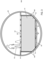
- FIG. 3 depicts inflatable fall protection pad 100 of FIGS. 1 and 2 in the inflated state as may be used within an aircraft fuselage 300.
- lower deck 330 of fuselage 300 refers to an example ground surface upon which the set of rollers 210 at least partially support pad 100.
- sidewalls 124C and 124D of pad 100 conform generally to structural features of fuselage 300, enabling pad 100 to be moved along lower deck 330 (e.g., along an axis orientated into and out of the page) via the set of rollers 210.
- person 132 is located within fuselage 300 above pad 100.
- portions of upper deck 310 identified schematically at 312 may be not present, representing gaps through which person 132 could fall.
- temporary floor panels installed to facilitate assembly of a portion of the fuselage may then be required to be removed in order to install permanent floor panels.
- open gaps between beams and other support structure may present a fall hazard for personnel working in the area.
- pad 100 occupies a volume of space beneath upper deck 310, the pad can arrest a fall of person 132 or otherwise support the weight of the person.
- An example load 320 applied to upper surface 122 is depicted schematically in FIG.
- regions of base wall 120 surrounding roller units 210 deforms to initiate or increase contact with ground surface 330.
- deformation of base wall 120 responsive to a load applied to upper surface 122 that initiates or increases contact with the ground surface can provide a braking function that increases lateral resistance to movement of the pad relative to the ground surface. For example, in some examples, contact of the ground surface under such a load may effectively prevent any lateral movement of the pad, stabilizing the pad in position until the load is removed.
- the pad may be configured to deform responsive to a load in locations other than of the base wall 120.
- one or more portions of side walls 124B, 124D may be configured to deform outward responsive to a load 320 on the upper surface 122, such as due to the arrangement of internal baffle walls or other interior structure. Such outward deformation of the side walls may be in addition to the deformation of the base wall 120. In an example such as shown in FIG.
- the pad in which the pad is of a shape and size to occupy an internal volume of a fuselage 300 that is bounded by a ground surface and other structural features such as vertical walls or beams, and depending on the amount of clearance between the exterior surfaces of the pad and these structural features, the pad may be configured so that such deformation may be of an extent to urge at least a portion of the exterior surface of the side walls against these structural features, such as to enhance lateral resistance to movement of the pad when it is under load.
- the exterior surface(s) of the side walls may incorporate a material having a desired coefficient of friction, for example to facilitate a braking function.
- FIG. 4A schematically depicts example behavior of a portion of inflatable fall protection pad 100 in the inflated state prior to a load being applied to upper wall 122.
- example roller units 410 and 412 of the set of roller units 210 are schematically depicted in contact with ground surface 130.
- roller units 410 and 412 at least partially support base wall 120 above ground surface 130.
- Roller units 410 and 412 can refer to any two neighboring roller units of set 210.
- Deformation of base wall 120 between roller units 410 and 412 due to the weight of pad 100 is depicted schematically at 420 in FIG. 4A . It will be understood that deformation of base wall 120 depicted schematically at 420 may contact ground surface 130 under the weight of pad 100, in some examples.
- FIG. 4B schematically depicts example behavior of the portion of inflatable fall protection pad 100 in the inflated state shown in FIG. 4A responsive to application of load being applied to upper wall 122.
- deformation of base wall 120 between roller units 410 and 412 depicted schematically at 430 due to application of the load to upper wall 122 has increased such that the base wall contacts ground surface 130.
- a surface area of base wall 120 that contacts ground surface 130 has increased relative to FIG. 4A , as depicted schematically at 432.
- the surface area of base wall 120 that contacts ground surface 130 may be located within region 260 of FIG. 2 , as an example.
- deformation of base wall 120 upon application of the load to upper wall 122 initiates and increases contact of the base wall with the ground surface. Additionally, a contact force between base wall 120 and ground surface 130 increases as a result of the load being applied to upper wall 122, thereby increasing a lateral resistance to movement of the pad along the ground surface due to friction. Such deformation and increased contact between base wall 120 and ground surface 130 provides a braking function that is responsive to the load applied to upper wall 122.
- base wall 120 does not contact the ground surface until a load applied to upper wall 122 attains or exceeds a predetermined magnitude.
- FIG. 4A can depict an example in which no load or a load applied to upper wall 122 is less than the predetermined magnitude
- FIG. 4B can depict an example in which the load applied to the upper wall attains or exceeds the predetermined magnitude.
- This approach can be used to initiate the braking function responsive to the load being applied to the upper wall attaining or exceeding the predetermined magnitude. This approach also supports mobility of the pad by the base wall not resisting movement of the pad over the ground surface when the load does not attain or exceed the predetermined magnitude.
- a "load of a predetermined magnitude" can describe a load that is localized to a given area of the upper wall.
- the pad may be configured (e.g., by means of a configuration of internal baffle walls or other interior structure) so that a portion of the bottom surface deforms sufficiently to contact the ground surface only when a load of a predetermined magnitude is applied within a given (e.g. localized) area of the top surface.
- Such examples may be useful in a context in which, for example, it may not be desirable for the bottom surface of the pad to "bottom out” against a ground surface due to the presence of tools or other objects on different areas of the top surface of the pad, even though the combined weight of such items may meet or exceed the predetermined magnitude, while still having the desired effect of the presence of such a load within a given area of the top surface, such as the weight of a person on the top surface, causing enough of the bottom surface of the pad to contact the ground surface that the pad is restricted from lateral movement until the load is removed.
- the pad may be configured so that the bottom surface will "bottom out” against a ground surface regardless of the position (or positions) of the predetermined load on the top surface.
- the set of roller units 210 include multiple roller units distributed over exterior-facing surface 220 of base wall 120.
- FIGS. 5A - 5D schematically depict examples of roller units 500A, 500B, 500C, and 500D that can be mounted to base wall 120 of inflatable fall protection pad 100.
- the example roller units of FIGS. 5A - 5D are schematically depicted from a bottom view facing upward from the ground surface.
- Each roller unit of the set of roller units 210 includes one or more rollers.
- rollers include wheels, wheeled casters, and ball casters.
- the one or more rollers of each roller unit of the set of roller units 210 can have a fixed rolling orientation along a single axis, such as a fixed axle wheel, or an omnidirectional rolling orientation within a plane, such as a wheeled caster or ball caster.
- sidewalls 124B and 124D of pad 100 taper between base wall 120 and upper wall 122 on opposite sides of deformable body 110.
- the opposite sides of the deformable body in this example can be parallel to the fixed rolling orientation of the set of rollers.
- the profile of sidewalls 124B and 124D configured to be accommodated by a particular structure can be oriented parallel to the fixed rolling orientation to enable pad 100 to be moved within or between features of the structure.
- Each roller unit can include one, two, three, or more wheels, wheeled casters, or ball rollers. Two or more fixed axle wheels of each roller unit having fixed rolling orientations can be aligned with each other along a common axis. In some examples, three, four, or more rollers of each roller unit can be arranged to form a polygon shape for localized stability of base wall 120, such as a three-sided triangular configuration, four-sided rectangular configuration, etc. In other examples, two or more rollers of each roller unit can be arranged along an axis in a linear configuration.
- Each roller unit includes a rigid body that interfaces with exterior-facing surface 220 of base wall 120 upon which the one or more rollers of the roller unit are rotatably mounted.
- the rigid body of each roller unit can provide a region of base wall 120 to which the rigid body is mounted that does not deform.
- the rigid body of each roller unit can be mounted to base wall 120 via one or more mechanical fasteners (e.g., bolts, rivets, screws, clips, etc.), hook and loop fasteners, adhesives, and/or stitching.
- Roller unit 500A of FIG. 5A includes four fixed axle wheels 510-1, 510-2, 510-3, and 510-4 rotatably mounted to a rigid body 512 in a rectangular configuration.
- Example mechanical fasteners 514 by which rigid body 512 can be mounted to base wall 120 are schematically depicted in FIG. 5A .
- Roller unit 500A has a fixed rolling orientation along axis 516 in this example.
- Roller unit 500B of FIG. 5B includes four wheeled casters 520-1, 520-2, 520-3, 520-4 rotatably mounted to a rigid body 522 in a rectangular configuration.
- Example mechanical fasteners 524 by which rigid body 522 can be mounted to base wall 120 are schematically depicted in FIG. 5B .
- Roller unit 500B has an omnidirectional rolling orientation within a plane as indicated by orthogonal axes 526 and 528.
- Roller unit 500B can alternatively include four ball casters.
- Roller unit 500C of FIG. 5C includes three ball casters 530-1, 530-2, and 530-3 rotatably mounted to a rigid body 532 in a triangular configuration.
- An example mechanical fastener 534 by which rigid body 532 can be mounted to base wall 120 is schematically depicted in FIG. 5C .
- Roller unit 500C has an omnidirectional rolling orientation within a plane as indicated by orthogonal axes 536 and 538.
- Roller unit 500C can alternatively include three wheeled casters or three fixed axle wheels.
- Roller unit 500D of FIG. 5D includes a single ball caster 540-1 rotatably mounted to a rigid body 542.
- Example mechanical fasteners 544-1, 544-2, 544-3, and 544-4 by which rigid body 542 can be mounted to base wall 120 are schematically depicted in FIG. 5D .
- Roller unit 500D has an omnidirectional rolling orientation within a plane as indicated by orthogonal axes 546 and 548.
- Roller unit 500D can alternatively include one wheeled caster or one fixed axle wheel.
- FIGS. 6A and 6B schematically depict an example roller unit 600 from a side view showing example fastening techniques for mounting the roller unit to base wall 120 of pad 100 along exterior-facing surface 220.
- roller unit 600 includes example rollers 610-1 and 610-2 rotatably mounted to a rigid body 612.
- rigid body 612 is mounted to base wall 120 along exterior-facing surface 220 via mechanical fasteners 614-1 and 614-2.
- a backing plate 620 is positioned on an opposite side of base wall 120 from roller unit 600. Mechanical fasteners 614-1 and 614-2, in this example, pass through base wall 120 and engage with backing plate 620.
- rigid body 612 is mounted to base wall 120 along exterior-facing surface 220 via hook and loop fasteners or an adhesive, represented schematically by reference numeral 630.
- Hook and loop fasteners can provide the advantage of enabling roller unit 600 to be removed from base wall 120 and/or repositioned at a different location or orientation relative to the base wall.
- base wall 120 can include a hook side or a loop side of hook and loop fasteners along some or all of exterior-facing surface 220 to enable the quantity, orientation, arrangement, and type of roller units of the set of roller units mounted to the base wall to be reconfigured for different applications.
- each roller unit includes a rigid body upon which one or more rollers are rotatably mounted.
- multiple roller units that form a row e.g., 240A-240D of FIG. 2
- a column e.g., 242A-242D of FIG. 2
- This configuration would not permit folding or rolling of deformable body 110 about a dimension that is orthogonal to the rows or columns that feature the shared rigid body that spans multiple roller units, but would permit folding or rolling of the deformable body about a dimension that is parallel to such rows or columns.
- rows 240A-240D can each feature multiple roller units that share a rigid body that spans the multiple roller units of that row.
- deformable body 110 can be folded and/or rolled about a dimension that is parallel to rows 240A-240D.
- deformation of base wall 120 can occur at one or more regions located between rows 240A-240D responsive to application of a load to upper wall 122.
- columns 242A-242D can each feature multiple roller units that share a rigid body that spans the multiple roller units of that column.
- deformable body 110 can be folded and/or rolled about a dimension that is parallel to columns 242A-242D.
- deformation of base wall 120 can occur at one or more regions located between columns 242A-242D responsive to application of a load to upper wall 122.
- FIGS. 7A, 7B, and 7C schematically depict additional examples of a set of roller units mounted to base wall 120 of inflatable fall protection pads.
- inflatable fall protection pad 100-7A includes multiple roller units 700 distributed over base wall 120 in rows and columns having a staggered configuration.
- inflatable fall protection pad 100-7B includes multiple roller units 700 distributed over base wall 120 in rows and columns in which a spacing between columns orientated parallel to a first midplane 710 decreases in each direction moving outward from the first midplane. Alternatively, the spacing between columns can increase or otherwise vary in each direction moving outward from first midplane 710.
- the arrangement of roller units 700 in FIG. 7B is symmetric about first midplane 710, in this example.
- a spacing between rows orientated parallel to a second midplane 712 that is orthogonal to the first midplane 710 is regular or consistent among rows, in this example.
- the arrangement of roller units 700 in FIG. 7B is symmetric about second midplane 712, in this example.
- inflatable fall protection pad 100-7C includes multiple roller units 700 distributed over base wall 120 in rows and columns in which a spacing between columns orientated parallel to first midplane 710 decreases in each direction moving outward from the first midplane. Alternatively, the spacing between columns can increase or otherwise vary in each direction moving outward from first midplane 710.
- the arrangement of roller units 700 in FIG. 7C is symmetric about midplane 710 in this example. Additionally, a spacing between rows orientated parallel to second midplane 712 decreases in each direction moving outward from the second midplane. Alternatively, the spacing between rows can increase or otherwise vary in each direction moving outward from second midplane 712.
- the arrangement of roller units 700 in FIG. 7C is symmetric about second midplane 712, in this example.
- the roller units in some examples may be configured to provide a self-braking feature, such as a braking feature that may be independent of the self-braking feature provided by the deformation of the bottom wall of the pad under load as discussed above. Further, such a braking feature may be "self-braking" in that it is responsive to a load being applied to the pad.
- a self-braking feature such as a braking feature that may be independent of the self-braking feature provided by the deformation of the bottom wall of the pad under load as discussed above.
- a braking feature may be "self-braking” in that it is responsive to a load being applied to the pad.
- 6A and 6B may be rotatably mounted to rigid body 612 by means of one or more axles that are spring-biased relative to rigid body 612, such that each of such axles is biased to provide a sufficient amount of vertical clearance between the top of the roller 610 and the exterior-facing surface 220 of base wall 120 so that the roller may roll when the pad is not bearing a load, such as a load of predetermined magnitude.
- the biasing of such axles may be calibrated (for example, by means of the configuration of the springs, the weight of the pad, the number of rollers, and so forth) so that this vertical clearance is reduced upon a load being applied to the pad, for example such that the rollers are urged into contact with the base wall 120 responsive to a load, for example a load of a predetermined magnitude applied to the top surface of the pad, in a manner that may effectively prevent the rollers from rolling due to friction and thereby arresting lateral movement of the pad.
- Other roller unit configurations may provide a similar self-braking feature.
- one or more of the roller units may provide such a self-braking feature in addition to, or as an alternative to, the braking feature provided by the deformation of the side and/or bottom wall(s) of the pad as discussed herein.
- FIGS. 8A, 8B, 8C, and 8D schematically depict an example of inflatable fall protection pad 100 in a deflated state being folded from an unfolded state to a folded state for storage. Additionally or alternatively, pad 100 can be rolled from an unrolled state to a rolled state for storage.
- FIG. 8A base wall 120 and the set of roller units 210 are visible.
- a plurality of available folding paths spanning pad 100 are depicted schematically in FIG. 8A at 810, 812, and 814 along first dimension 232, and at 820, 822, and 824 along second dimension 234 that is orthogonal to the first dimension.
- pad 100 can be folded as indicated by reference numeral 830 along folding path 822 to obtain the folded configuration of FIG. 8B in which the upper wall 122 is now visible.
- pad 100 can be folded again along folding path 812 as indicated by reference numeral 832 to obtain the folded configuration of FIG. 8C .
- FIG. 830 pad 100 can be folded again along folding path 812 as indicated by reference numeral 832 to obtain the folded configuration of FIG. 8C .
- pad 100 can be folded again along folding paths 810 / 814 as indicated by reference numeral 834 to obtain the folded configuration of FIG. 8D . It will be understood that pad 100 can be folded in various ways along one or more folding paths that are located along one or more regions of deformable body 110 that do not have one or more roller units mounted to the base wall 120.
- FIG. 9 is a flow diagram depicting illustrative, non-exclusive examples of method 900 of using an inflatable fall protection pad that includes a plurality of rollers.
- some steps may be optional or may correspond to an optional version of a method according to the present disclosure. That said, not all methods according to the present disclosure are required to include the steps illustrated.
- the methods and steps illustrated in Fig. 9 are not limiting and other methods and steps are within the scope of the present disclosure, including methods having greater than or fewer than the number of steps illustrated, and/or may include steps in a different order, as understood from the discussions herein.
- method 900 can be performed using inflatable fall protection pad 100 having a plurality of roller units 210 mounted to base wall 120, as described herein.
- the method includes obtaining an inflatable fall protection pad (e.g., 100) that includes a plurality of rollers.
- an inflatable fall protection pad e.g., 100
- the method includes unfolding and/or unrolling the pad from a folded and/or rolled state to obtain an unfolded and unrolled state of the pad.
- the method includes inflating the pad from the deflated state to obtain the inflated state of the pad.
- fan assembly 150 of FIG. 1 can be operated to supply air to pad 100 via conduit 154 and opening 152.
- the method includes positioning the pad at a target positioning, which can include a target location and/or orientation.
- a target positioning can include a target location and/or orientation.
- the pad can be moved at 918 by rolling the pad over a ground surface upon the rollers of the plurality of roller units mounted to the base wall.
- the method can return to 916 wherein the pad can be repositioned at the target positioning.
- the method can proceed to 932.
- the method includes deflating the pad from the inflated state to obtain the deflated state of the pad.
- fan assembly 150 of FIG. 1 can be turned off and/or disconnected from opening 152 and/or conduit 154 of pad 100.
- the method includes folding and/or rolling the pad from the unfolded and unrolled state to obtain the folded and/or rolled state of the pad suitable for storage.
- the method includes applying a load to an upper wall of the pad.
- the load applied to the upper wall of the pad can attain or exceed a predetermined magnitude at which the braking function is initiated due, at least in part, to deformation of the base wall of the pad to initiate contact with the ground surface. Additionally or alternatively, the braking function can be initiated due to deformation of sidewalls of the pad to initiate contact with surrounding structures.
- the method includes deforming the base wall of the pad responsive to the load being applied to the upper wall to initiate or increase contact of the base wall with the ground surface. Additionally, the sidewalls of the pad may be deformed at 926 responsive to the load applied at 924 to initiate or increase contact of the sidewalls with surrounding structures. Increased contact of the base wall with the ground surface can provide a braking function, as previously described. Additionally or alternatively, deformation of the sidewalls can initiate and/or increase contact between the side walls and surrounding structures, thereby providing the braking function. Referring again to FIG. 3 , for example, sidewalls 124B and 124D can deform under the applied load to initiated contact or increase contact with surrounding structures of aircraft fuselage 300.
- the method includes removing the load applied to the upper wall of the pad.
- contact of the base wall with the ground surface is reduced or discontinued responsive to removal of the load. Additionally or alternatively, contact of the sidewalls with surrounding structures is reduced or discontinued responsive to removal of the load.
- a method may include positioning the pad at a target positioning location (at 916 and/or 918) prior to inflating it (at 914), and so forth.
- a method may include positioning the pad (at 916 and/or 918), inflating the pad (at 914), and then orienting the pad (at 916).
- An inflatable fall protection pad comprising: a deformable body defining an inflatable three-dimensional volume, the deformable body having a base wall, an upper wall, and sidewalls spanning the base wall and the upper wall; and a set of roller units mounted to the base wall along an exterior-facing surface of the base wall, the set of roller units arranged in a multi-dimensional array, wherein two or more roller units of the set are spaced apart from each other in a first dimension of the multi-dimensional array, and wherein two or more roller units of the set are spaced apart from each other in a second dimension of the multi-dimensional array that is orthogonal to the first dimension.
- Clause 8 The inflatable fall protection pad of clause 7, wherein contact of the ground surface by a portion of the base wall increases a lateral resistance to movement of the inflatable fall protection pad along the ground surface.
- Clause 11 The inflatable fall protection pad of clause 9 or 10, wherein contact of the ground surface by a portion of the base wall increases a lateral resistance to movement of the inflatable fall protection pad along the ground surface, and wherein the lateral resistance increases as the surface area of the base wall in contact with the ground surface increases.
- each roller unit of the set of roller units includes: a rigid body that interfaces with the exterior-facing surface of the base wall, and one or more rollers rotatably mounted to the rigid body.
- each roller unit of the set of roller units is mounted to the base wall at a respective location within a region bounded on at least two opposing sides by baffle walls of the plurality of internal baffle walls that interface with the interior-facing surface of the base wall.
- the inflatable fall protection pad of clause 20 further comprising a fan assembly interfacing with the opening to inflate the inflatable three-dimensional volume defined by the deformable body; wherein the fan assembly includes another set of rollers.
Landscapes
- Health & Medical Sciences (AREA)
- General Health & Medical Sciences (AREA)
- Business, Economics & Management (AREA)
- Emergency Management (AREA)
- Buildings Adapted To Withstand Abnormal External Influences (AREA)
- Emergency Lowering Means (AREA)
- Mattresses And Other Support Structures For Chairs And Beds (AREA)
Abstract
Description
- This application claims priority to
U.S. Patent Application Serial No. 63/508,980, filed June 19, 2023 - The subject matter of the present disclosure relates generally to fall protection pads for restraining falls by persons or objects, and more particularly to a mobile inflatable fall protection pad that feature rollers to assist in moving the pad over a ground surface.
- Manufacturing and maintenance environments involve personnel working on structures that can be in a partially assembled or disassembled state. As an example, mobile structures such as aircraft frames or other large machinery as well as stationary structures such as buildings can involve personnel working at heights from which a fall could cause injury. When such structures are in a partially assembled or disassembled state, floors, walls, and railings may not be present, thereby providing locations where personnel could fall while performing manufacturing or maintenance tasks.
- An inflatable fall protection pad comprises a deformable body defining an inflatable three-dimensional volume. The deformable body has a base wall, an upper wall, and sidewalls spanning the base wall and the upper wall. The inflatable fall protection pad further comprises a set of roller units mounted to the base wall along an exterior-facing surface of the base wall. The set of roller units is arranged in a multi-dimensional array. Two or more roller units of the set are spaced apart from each other in a first dimension of the multi-dimensional array. Two or more roller units of the set are spaced apart from each other in a second dimension of the multi-dimensional array that is orthogonal to the first dimension.
-
-
FIG. 1 schematically depicts an example inflatable fall protection pad in an inflated state. -
FIG. 2 schematically depicts another view of the inflatable fall protection pad ofFIG. 1 in the inflated state. -
FIG. 3 depicts the inflatable fall protection pad ofFIGS. 1 and2 in the inflated state used within an example aircraft fuselage. -
FIG. 4A schematically depicts example behavior of a portion of the inflatable fall protection pad ofFIGS. 1 and2 in the inflated state prior to a load being applied to an upper wall of the pad. -
FIG. 4B schematically depicts example behavior of the portion of the inflatable fall protection pad ofFIG. 4A in the inflated state responsive to application of a load to the upper wall of the pad. -
FIGS. 5A, 5B, 5C, and 5D depict example roller units of the inflatable fall protection pad ofFIGS. 1 and2 . -
FIGS. 6A and 6B schematically depict an example roller unit showing example fastening techniques for mounting the roller unit to a base wall of the inflatable fall protection pad ofFIGS. 1 and2 . -
FIGS. 7A, 7B, and 7C schematically depict additional examples of a set of roller units mounted to the base wall of inflatable fall protection pads in accordance with the present disclosure. -
FIGS. 8A, 8B, 8C, and 8D schematically depict an example of folding the inflatable fall protection pad ofFIGS. 1 and2 in a deflated state. -
FIG. 9 is a flow diagram depicting an example method of using the inflatable fall protection pad ofFIGS. 1 and2 . - As described in further detail herein, an inflatable fall protection pad comprises a deformable body defining an inflatable three-dimensional volume. The deformable body has a base wall, an upper wall, and sidewalls spanning the base wall and the upper wall. The inflatable fall protection pad further comprises a set of roller units mounted to the base wall along an exterior-facing surface of the base wall. The set of roller units is arranged in a multi-dimensional array. Two or more roller units of the set are spaced apart from each other in a first dimension of the multi-dimensional array. Two or more roller units of the set are spaced apart from each other in a second dimension of the multi-dimensional array that is orthogonal to the first dimension.
- The set of roller units of the inflatable fall protection pad enable the pad to be rolled over a ground surface. As an example, the pad can be of a mass, area, or volume that would otherwise be difficult for a person or group of people to move in the absence of the roller units due friction between the base wall and the ground surface.
- As the set of roller units are spaced apart from each other over an area defined by the base wall, the deformable body of the pad, when deflated, can be folded for storage along one or more folding paths located between the roller units in both the first dimension and the second dimension. Additionally or alternatively, the deformable body of the pad can be rolled for storage.
- Furthermore, a load applied to the upper wall, such as while arresting a fall, or otherwise supporting the weight of a person, can influence the mobility of the inflatable fall protection pad. As the set of roller units are spaced apart from each other over an area defined by the base wall, deformation of the base wall upon application of a load to the upper wall can cause the base wall to deform toward the ground surface. Such deformation can cause the base wall to initiate or increase contact with the ground surface. For example, one or more regions of the base wall located between the set of rollers can deform to contact the ground surface under a load applied to the upper wall, thereby increasing a lateral resistance to movement of the pad along the ground surface due to friction. Such deformation and increased contact between the base wall and the ground surface can provide a braking function having a braking force that is responsive to a load applied to the upper wall. The braking function can assist in stabilizing the pad. As the magnitude of the load increases, contact of the base wall with the ground surface can increase, thereby increasing the lateral resistance to movement of the pad along the ground surface.
- In some examples, the set of roller units can be sized and arranged upon the base wall of the pad such that the base wall initiates contact with the ground surface responsive to a load being applied to the upper wall that attains or exceeds a predetermined magnitude. In this example, the base wall does not contact the ground surface when no load or a load that is less than the predetermined magnitude is applied to the upper wall of the pad. This approach can support mobility of the pad under conditions in which objects that do not attain or exceed the predetermined magnitude are supported by the upper wall of the pad. This approach also enables the braking function discussed above to be provided under select conditions in which a load applied to the upper wall attains or exceeds the predetermined magnitude.
- As an example, the predetermined magnitude of the load can be selected to correspond to the static weight of a sample human adult applied to the upper wall. In this example or other examples, a conservative weight estimate of an adult can be used, such as 100 pounds or other suitable value, as an illustrative example. As another example, the predetermined magnitude can be selected to correspond to the dynamic force of a human adult falling from a given distance. As yet another example, the predetermined magnitude of the load can be selected to correspond to the static weight or dynamic force of a child.
-
FIG. 1 schematically depicts an example inflatablefall protection pad 100 in an inflated state.Pad 100 includes adeformable body 110 defining an inflatable three-dimensional volume 112.Body 110 has abase wall 120, anupper wall 122, andsidewalls - In at least some examples,
body 110 can be formed from a flexible textile material or flexible continuous sheet material. Such materials can include a polymer such as nylon, vinyl, Polyvinyl chloride (PVC) and/or natural fiber, as examples. Textile materials can be treated with a polymer coating in at least some examples to reduce air permeability and/or provide water resistance. - As described in further detail with reference to
FIG. 2 , pad 100 further comprises a set of roller units mounted tobase wall 120. The set of roller units enablepad 100 to be rolled along aground surface 130. In at least some examples,body 110 ofpad 100 is of a size, weight, or volume that would otherwise be difficult for a person or group of people to move in the absence of the set of roller units due to friction betweenbase wall 120 andground surface 130.FIG. 1 schematically depicts aperson 132 in relation tobody 110 ofpad 100 to provide an example scale ofbody 110. It will be understood thatbody 110 can be of other suitable size and/or shape. - In at least some examples,
upper wall 122 andbase wall 120 have different areas, and sidewalls 124B and 124D taper between the base wall and the upper wall on opposite sides ofbody 110. In the example depicted inFIG. 1 ,upper wall 122 has a larger area thanbase wall 120, andsidewalls taper body 110.Sidewalls respective profiles 144B and 144D that are shaped to accommodate a physical structure within or between whichpad 100 can be used. As an example, the physical structure can include an interior of a fuselage of an aircraft, as described in further detail with reference toFIG. 3 . It will be understood thatbody 110 can be of other suitable shape. -
FIG. 1 schematically depicts anexample fan assembly 150 that can be used to inflatebody 110 and maintainbody 110 in the inflated state. In this example,body 110 includes anopening 152 by which air is provided to inflate three-dimensional volume 112 defined bybody 110. As an example, sidewall 124A definesopening 152. An outflow offan assembly 150 can be fluidly coupled withopening 152 via a flexible orrigid conduit 154. In at least some examples,conduit 154 can form part ofbody 110. As another example, an outflow offan assembly 150 can be mounted directly toopening 152. In at least some examples,fan assembly 150 can be mounted upon a set of rollers that enables the fan assembly to follow afterpad 110 as the pad is moved between locations. In this example,conduit 154 also serves as a tether by whichfan assembly 150 is mounted tobody 110. -
FIG. 2 schematically depicts another view of inflatablefall protection pad 100 ofFIG. 1 in the inflated state in whichbase wall 120 is visible. In this example,base wall 120 has a rectangular shape. In other examples,base wall 120 can have a polygon shape of three, four, five or more sides. In other examples, base wall can have a circular shape, oval shape, or irregular shape. -
Pad 100 includes a set ofroller units 210 mounted tobase wall 120 along an exterior-facingsurface 220 of the base wall. The set ofroller units 210 are arranged in amulti-dimensional array 230. Two ormore roller units 212 ofset 210 are spaced apart from each other in afirst dimension 232 ofmulti-dimensional array 230, and two ormore roller units 214 of theset 210 are spaced apart from each other in asecond dimension 234 ofmulti-dimensional array 230 that is orthogonal to the first dimension. - As the set of
roller units 210 are spaced apart from each other over an area defined bybase wall 120, deformation of the base wall upon application of a load toupper wall 122 can initiate or increase contact of the base wall with the ground surface. For example, one or more regions ofbase wall 120 surrounding and located between the set ofroller units 210, such asexample region 260 can deform to contact or increase contact with the ground surface under a load applied toupper wall 122, thereby increasing a lateral resistance to movement of the pad along the ground surface due to friction. Such deformation and increased contact betweenbase wall 120 and the ground surface can provide a braking function having a braking force that is responsive to a load applied to the upper wall. - In at least some examples, exterior-facing
surface 220 ofbase wall 120 comprises a different material than an exterior-facing surface ofupper wall 122 and/or sidewalls. As an example, exterior-facingsurface 220 ofbase wall 120 can comprise a material having a higher coefficient of friction as compared to a material of exterior-facing surface ofupper wall 122 and/or the sidewalls to facilitate the braking function described herein, for example due to the material's composition, texture, and so forth. In various and non-limiting examples of this,surface 220 can be made from such a material, or incorporate such a material, or be at least partially covered with such a material. - In at least some examples, the set of
roller units 210 is arranged in two, three, four ormore rows multi-dimensional array 230 in which each row includes two or more roller units. In the example depicted inFIG. 2 , each row includes four roller units, such asroller units row 240A. Each row of the set ofroller units 210 can be spaced apart from each other at regular intervals (e.g., equal spacing), in an example. As another example, spacing between rows can vary acrossbase wall 120 alongfirst dimension 232. In still other examples, the set ofroller units 210 is not arranged in rows. - In at least some examples, the set of
roller units 210 is arranged in two, three, four ormore columns multi-dimensional array 230 in which each column includes a roller unit of each row. In the example depicted inFIG. 2 , each column includes four roller units, such asroller units column 242A. Each column of the set ofroller units 210 can be spaced apart from each other at regular intervals (e.g., equal spacing), as an example. As another example, spacing between columns can vary acrossbase wall 120 alongsecond dimension 234. In still other examples, the set ofroller units 210 is not arranged in columns. - Furthermore, as described in further detail with reference to
FIGS. 7A, 7B, and 7C , in at least some examples, the set ofroller units 210 can be arranged symmetrically about a midplane ofdeformable body 110 that bisectsbase wall 120 along an axis that is parallel tofirst dimension 232. Additionally or alternatively, the set ofroller units 210 can be arranged symmetrically about a midplane ofdeformable body 110 that bisectsbase wall 120 along an axis that is parallel tosecond dimension 234. Symmetry of roller unit arrangement about one or both midplanes ofdeformable body 110 can provide consistent performance and/or responsiveness ofpad 100 in terms of mobility and braking function. - In the example of
FIG. 2 , the set ofroller units 210 includes sixteen roller units distributed overbase wall 120 that are arranged in a four by four array. It will be understood that other suitable quantities and/or arrangements of roller units can be distributed acrossbase wall 120 to enablepad 100 to be rolled across a ground surface with a given lateral force applied to the pad. For a given application, the quantity and arrangement of roller units mounted tobase wall 100 can be selected to provide a suitable level of mobility whenupper wall 122 is unloaded as well as a suitable level of braking force when a load is applied toupper wall 122. - As an example, to support mobility of
pad 100, a quantity of roller units per unit area ofbase wall 120 can be selected to provide a desired level of lateral resistance to movement ofpad 100 along a ground surface when a load is not being applied toupper wall 122. For example, lateral resistance tomovement pad 100 along a ground surface whenupper wall 122 is unloaded can be reduced by increasing a quantity of roller units per unit area ofbase wall 120. - To support a braking function, the quantity of roller units per unit area of
base wall 120 can be selected to provide a desired level of lateral resistance to movement ofpad 100 along a ground surface when a load is applied toupper wall 122. For example, a braking force provided in response to application of a load toupper wall 122 can be increased by reducing a quantity of roller units per unit area ofbase wall 120. - In at least some examples,
deformable body 110 includes a plurality of internal baffle walls within the inflatable three-dimensional volume that interface with an interior-facing surface ofbase wall 120. In such examples, each roller unit of the set ofroller units 210 can be mounted tobase wall 120 at a respective location within a region bounded on at least two opposing sides by baffle walls of the plurality of internal baffle walls that interface with the interior-facing surface of the base wall. As an example,reference numeral 290 inFIG. 2 depicts an example region bounded on opposing sides by baffle walls within which a roller unit of the set ofroller units 210 is mounted. This mounting approach can facilitate the braking function by locating the roller units within regions ofbase wall 120 that exhibit greater deformation than regions secured to baffle walls. -
FIG. 3 depicts inflatablefall protection pad 100 ofFIGS. 1 and2 in the inflated state as may be used within anaircraft fuselage 300. In this example,lower deck 330 offuselage 300 refers to an example ground surface upon which the set ofrollers 210 at least partially supportpad 100. Furthermore, in this example, sidewalls 124C and 124D ofpad 100 conform generally to structural features offuselage 300, enablingpad 100 to be moved along lower deck 330 (e.g., along an axis orientated into and out of the page) via the set ofrollers 210. - Within
FIG. 3 ,person 132 is located withinfuselage 300 abovepad 100. During manufacturing or maintenance offuselage 300, for example, portions ofupper deck 310 identified schematically at 312 may be not present, representing gaps through whichperson 132 could fall. As an example, temporary floor panels installed to facilitate assembly of a portion of the fuselage may then be required to be removed in order to install permanent floor panels. After removal of the temporary floor panels and prior to installation of permanent floor panels, open gaps between beams and other support structure may present a fall hazard for personnel working in the area. Aspad 100 occupies a volume of space beneathupper deck 310, the pad can arrest a fall ofperson 132 or otherwise support the weight of the person. Anexample load 320 applied toupper surface 122 is depicted schematically inFIG. 3 , which can represent the static weight or dynamic force ofperson 132 uponpad 100. As depicted schematically at 332, regions ofbase wall 120 surroundingroller units 210 deforms to initiate or increase contact withground surface 330. As previously described, deformation ofbase wall 120 responsive to a load applied toupper surface 122 that initiates or increases contact with the ground surface can provide a braking function that increases lateral resistance to movement of the pad relative to the ground surface. For example, in some examples, contact of the ground surface under such a load may effectively prevent any lateral movement of the pad, stabilizing the pad in position until the load is removed. - In some examples, the pad may be configured to deform responsive to a load in locations other than of the
base wall 120. For example, referring to thepad 100 ofFIG. 3 , one or more portions ofside walls load 320 on theupper surface 122, such as due to the arrangement of internal baffle walls or other interior structure. Such outward deformation of the side walls may be in addition to the deformation of thebase wall 120. In an example such as shown inFIG. 3 , in which the pad is of a shape and size to occupy an internal volume of afuselage 300 that is bounded by a ground surface and other structural features such as vertical walls or beams, and depending on the amount of clearance between the exterior surfaces of the pad and these structural features, the pad may be configured so that such deformation may be of an extent to urge at least a portion of the exterior surface of the side walls against these structural features, such as to enhance lateral resistance to movement of the pad when it is under load. In such examples, the exterior surface(s) of the side walls may incorporate a material having a desired coefficient of friction, for example to facilitate a braking function. -
FIG. 4A schematically depicts example behavior of a portion of inflatablefall protection pad 100 in the inflated state prior to a load being applied toupper wall 122. WithinFIG. 4A ,example roller units roller units 210 are schematically depicted in contact withground surface 130. Also withinFIG. 4A ,roller units base wall 120 aboveground surface 130.Roller units set 210. Deformation ofbase wall 120 betweenroller units pad 100 is depicted schematically at 420 inFIG. 4A . It will be understood that deformation ofbase wall 120 depicted schematically at 420 may contactground surface 130 under the weight ofpad 100, in some examples. -
FIG. 4B schematically depicts example behavior of the portion of inflatablefall protection pad 100 in the inflated state shown inFIG. 4A responsive to application of load being applied toupper wall 122. WithinFIG. 4B , deformation ofbase wall 120 betweenroller units upper wall 122 has increased such that the base wallcontacts ground surface 130. Responsive to application of the load toupper wall 122, a surface area ofbase wall 120 that contacts groundsurface 130 has increased relative toFIG. 4A , as depicted schematically at 432. The surface area ofbase wall 120 that contacts groundsurface 130 may be located withinregion 260 ofFIG. 2 , as an example. - In this example, deformation of
base wall 120 upon application of the load toupper wall 122 initiates and increases contact of the base wall with the ground surface. Additionally, a contact force betweenbase wall 120 andground surface 130 increases as a result of the load being applied toupper wall 122, thereby increasing a lateral resistance to movement of the pad along the ground surface due to friction. Such deformation and increased contact betweenbase wall 120 andground surface 130 provides a braking function that is responsive to the load applied toupper wall 122. - In at least some examples,
base wall 120 does not contact the ground surface until a load applied toupper wall 122 attains or exceeds a predetermined magnitude. For example,FIG. 4A can depict an example in which no load or a load applied toupper wall 122 is less than the predetermined magnitude, andFIG. 4B can depict an example in which the load applied to the upper wall attains or exceeds the predetermined magnitude. This approach can be used to initiate the braking function responsive to the load being applied to the upper wall attaining or exceeding the predetermined magnitude. This approach also supports mobility of the pad by the base wall not resisting movement of the pad over the ground surface when the load does not attain or exceed the predetermined magnitude. In some examples, a "load of a predetermined magnitude" can describe a load that is localized to a given area of the upper wall. In other words, in some examples, the pad may be configured (e.g., by means of a configuration of internal baffle walls or other interior structure) so that a portion of the bottom surface deforms sufficiently to contact the ground surface only when a load of a predetermined magnitude is applied within a given (e.g. localized) area of the top surface. Such examples may be useful in a context in which, for example, it may not be desirable for the bottom surface of the pad to "bottom out" against a ground surface due to the presence of tools or other objects on different areas of the top surface of the pad, even though the combined weight of such items may meet or exceed the predetermined magnitude, while still having the desired effect of the presence of such a load within a given area of the top surface, such as the weight of a person on the top surface, causing enough of the bottom surface of the pad to contact the ground surface that the pad is restricted from lateral movement until the load is removed. In other examples, the pad may be configured so that the bottom surface will "bottom out" against a ground surface regardless of the position (or positions) of the predetermined load on the top surface. - As previously described with reference to
FIG. 2 , the set ofroller units 210 include multiple roller units distributed over exterior-facingsurface 220 ofbase wall 120.FIGS. 5A - 5D schematically depict examples ofroller units base wall 120 of inflatablefall protection pad 100. The example roller units ofFIGS. 5A - 5D are schematically depicted from a bottom view facing upward from the ground surface. - Each roller unit of the set of
roller units 210 includes one or more rollers. Examples of rollers include wheels, wheeled casters, and ball casters. The one or more rollers of each roller unit of the set ofroller units 210 can have a fixed rolling orientation along a single axis, such as a fixed axle wheel, or an omnidirectional rolling orientation within a plane, such as a wheeled caster or ball caster. - As previously described with reference to
FIGS. 1 and2 ,sidewalls pad 100 taper betweenbase wall 120 andupper wall 122 on opposite sides ofdeformable body 110. The opposite sides of the deformable body in this example can be parallel to the fixed rolling orientation of the set of rollers. Thus, in this example, the profile ofsidewalls pad 100 to be moved within or between features of the structure. - Each roller unit can include one, two, three, or more wheels, wheeled casters, or ball rollers. Two or more fixed axle wheels of each roller unit having fixed rolling orientations can be aligned with each other along a common axis. In some examples, three, four, or more rollers of each roller unit can be arranged to form a polygon shape for localized stability of
base wall 120, such as a three-sided triangular configuration, four-sided rectangular configuration, etc. In other examples, two or more rollers of each roller unit can be arranged along an axis in a linear configuration. - Each roller unit includes a rigid body that interfaces with exterior-facing
surface 220 ofbase wall 120 upon which the one or more rollers of the roller unit are rotatably mounted. The rigid body of each roller unit can provide a region ofbase wall 120 to which the rigid body is mounted that does not deform. The rigid body of each roller unit can be mounted tobase wall 120 via one or more mechanical fasteners (e.g., bolts, rivets, screws, clips, etc.), hook and loop fasteners, adhesives, and/or stitching. -
Roller unit 500A ofFIG. 5A includes four fixed axle wheels 510-1, 510-2, 510-3, and 510-4 rotatably mounted to arigid body 512 in a rectangular configuration. Examplemechanical fasteners 514 by whichrigid body 512 can be mounted tobase wall 120 are schematically depicted inFIG. 5A .Roller unit 500A has a fixed rolling orientation alongaxis 516 in this example. -
Roller unit 500B ofFIG. 5B includes four wheeled casters 520-1, 520-2, 520-3, 520-4 rotatably mounted to arigid body 522 in a rectangular configuration. Examplemechanical fasteners 524 by whichrigid body 522 can be mounted tobase wall 120 are schematically depicted inFIG. 5B .Roller unit 500B has an omnidirectional rolling orientation within a plane as indicated byorthogonal axes Roller unit 500B can alternatively include four ball casters. -
Roller unit 500C ofFIG. 5C includes three ball casters 530-1, 530-2, and 530-3 rotatably mounted to arigid body 532 in a triangular configuration. An examplemechanical fastener 534 by whichrigid body 532 can be mounted tobase wall 120 is schematically depicted inFIG. 5C .Roller unit 500C has an omnidirectional rolling orientation within a plane as indicated byorthogonal axes Roller unit 500C can alternatively include three wheeled casters or three fixed axle wheels. -
Roller unit 500D ofFIG. 5D includes a single ball caster 540-1 rotatably mounted to arigid body 542. Example mechanical fasteners 544-1, 544-2, 544-3, and 544-4 by whichrigid body 542 can be mounted tobase wall 120 are schematically depicted inFIG. 5D .Roller unit 500D has an omnidirectional rolling orientation within a plane as indicated byorthogonal axes Roller unit 500D can alternatively include one wheeled caster or one fixed axle wheel. -
FIGS. 6A and 6B schematically depict anexample roller unit 600 from a side view showing example fastening techniques for mounting the roller unit tobase wall 120 ofpad 100 along exterior-facingsurface 220. In this example,roller unit 600 includes example rollers 610-1 and 610-2 rotatably mounted to arigid body 612. - Within
FIG. 6A ,rigid body 612 is mounted tobase wall 120 along exterior-facingsurface 220 via mechanical fasteners 614-1 and 614-2. Furthermore, in this example, abacking plate 620 is positioned on an opposite side ofbase wall 120 fromroller unit 600. Mechanical fasteners 614-1 and 614-2, in this example, pass throughbase wall 120 and engage withbacking plate 620. - Within
FIG. 6B ,rigid body 612 is mounted tobase wall 120 along exterior-facingsurface 220 via hook and loop fasteners or an adhesive, represented schematically byreference numeral 630. - Hook and loop fasteners can provide the advantage of enabling
roller unit 600 to be removed frombase wall 120 and/or repositioned at a different location or orientation relative to the base wall. As an example,base wall 120 can include a hook side or a loop side of hook and loop fasteners along some or all of exterior-facingsurface 220 to enable the quantity, orientation, arrangement, and type of roller units of the set of roller units mounted to the base wall to be reconfigured for different applications. - In the examples depicted in
FIGS. 5A-5D and6A-6B , each roller unit includes a rigid body upon which one or more rollers are rotatably mounted. In another example, multiple roller units that form a row (e.g., 240A-240D ofFIG. 2 ) or a column (e.g., 242A-242D ofFIG. 2 ) can share a rigid body that spans the multiple roller units. This configuration would not permit folding or rolling ofdeformable body 110 about a dimension that is orthogonal to the rows or columns that feature the shared rigid body that spans multiple roller units, but would permit folding or rolling of the deformable body about a dimension that is parallel to such rows or columns. Referring toFIG. 2 , for example,rows 240A-240D can each feature multiple roller units that share a rigid body that spans the multiple roller units of that row. In this example,deformable body 110 can be folded and/or rolled about a dimension that is parallel torows 240A-240D. Furthermore, in this example, deformation ofbase wall 120 can occur at one or more regions located betweenrows 240A-240D responsive to application of a load toupper wall 122. As another example,columns 242A-242D can each feature multiple roller units that share a rigid body that spans the multiple roller units of that column. In this example,deformable body 110 can be folded and/or rolled about a dimension that is parallel tocolumns 242A-242D. Furthermore, in this example, deformation ofbase wall 120 can occur at one or more regions located betweencolumns 242A-242D responsive to application of a load toupper wall 122. -
FIGS. 7A, 7B, and 7C schematically depict additional examples of a set of roller units mounted tobase wall 120 of inflatable fall protection pads. - In
FIG. 7A , inflatable fall protection pad 100-7A includesmultiple roller units 700 distributed overbase wall 120 in rows and columns having a staggered configuration. - In
FIG. 7B , inflatable fall protection pad 100-7B includesmultiple roller units 700 distributed overbase wall 120 in rows and columns in which a spacing between columns orientated parallel to afirst midplane 710 decreases in each direction moving outward from the first midplane. Alternatively, the spacing between columns can increase or otherwise vary in each direction moving outward fromfirst midplane 710. The arrangement ofroller units 700 inFIG. 7B is symmetric aboutfirst midplane 710, in this example. A spacing between rows orientated parallel to asecond midplane 712 that is orthogonal to thefirst midplane 710 is regular or consistent among rows, in this example. The arrangement ofroller units 700 inFIG. 7B is symmetric aboutsecond midplane 712, in this example. - In
FIG. 7C , inflatable fall protection pad 100-7C includesmultiple roller units 700 distributed overbase wall 120 in rows and columns in which a spacing between columns orientated parallel tofirst midplane 710 decreases in each direction moving outward from the first midplane. Alternatively, the spacing between columns can increase or otherwise vary in each direction moving outward fromfirst midplane 710. The arrangement ofroller units 700 inFIG. 7C is symmetric aboutmidplane 710 in this example. Additionally, a spacing between rows orientated parallel tosecond midplane 712 decreases in each direction moving outward from the second midplane. Alternatively, the spacing between rows can increase or otherwise vary in each direction moving outward fromsecond midplane 712. The arrangement ofroller units 700 inFIG. 7C is symmetric aboutsecond midplane 712, in this example. - Although not shown in the drawings, the roller units in some examples may be configured to provide a self-braking feature, such as a braking feature that may be independent of the self-braking feature provided by the deformation of the bottom wall of the pad under load as discussed above. Further, such a braking feature may be "self-braking" in that it is responsive to a load being applied to the pad. For example, the rollers 610 of the
example roller units 600 depicted inFIGS. 6A and 6B may be rotatably mounted torigid body 612 by means of one or more axles that are spring-biased relative torigid body 612, such that each of such axles is biased to provide a sufficient amount of vertical clearance between the top of the roller 610 and the exterior-facingsurface 220 ofbase wall 120 so that the roller may roll when the pad is not bearing a load, such as a load of predetermined magnitude. However, the biasing of such axles may be calibrated (for example, by means of the configuration of the springs, the weight of the pad, the number of rollers, and so forth) so that this vertical clearance is reduced upon a load being applied to the pad, for example such that the rollers are urged into contact with thebase wall 120 responsive to a load, for example a load of a predetermined magnitude applied to the top surface of the pad, in a manner that may effectively prevent the rollers from rolling due to friction and thereby arresting lateral movement of the pad. Other roller unit configurations may provide a similar self-braking feature. In some examples, one or more of the roller units may provide such a self-braking feature in addition to, or as an alternative to, the braking feature provided by the deformation of the side and/or bottom wall(s) of the pad as discussed herein. -
FIGS. 8A, 8B, 8C, and 8D schematically depict an example of inflatablefall protection pad 100 in a deflated state being folded from an unfolded state to a folded state for storage. Additionally or alternatively, pad 100 can be rolled from an unrolled state to a rolled state for storage. - In
FIG. 8A ,base wall 120 and the set ofroller units 210 are visible. A plurality of available foldingpaths spanning pad 100 are depicted schematically inFIG. 8A at 810, 812, and 814 alongfirst dimension 232, and at 820, 822, and 824 alongsecond dimension 234 that is orthogonal to the first dimension. As an example, pad 100 can be folded as indicated byreference numeral 830 alongfolding path 822 to obtain the folded configuration ofFIG. 8B in which theupper wall 122 is now visible. As another example shown inFIG. 8B ,pad 100 can be folded again along foldingpath 812 as indicated byreference numeral 832 to obtain the folded configuration ofFIG. 8C . As another example shown inFIG. 8C ,pad 100 can be folded again alongfolding paths 810 / 814 as indicated byreference numeral 834 to obtain the folded configuration ofFIG. 8D . It will be understood thatpad 100 can be folded in various ways along one or more folding paths that are located along one or more regions ofdeformable body 110 that do not have one or more roller units mounted to thebase wall 120. -
FIG. 9 is a flow diagram depicting illustrative, non-exclusive examples ofmethod 900 of using an inflatable fall protection pad that includes a plurality of rollers. As is evident from the following description, some steps may be optional or may correspond to an optional version of a method according to the present disclosure. That said, not all methods according to the present disclosure are required to include the steps illustrated. The methods and steps illustrated inFig. 9 are not limiting and other methods and steps are within the scope of the present disclosure, including methods having greater than or fewer than the number of steps illustrated, and/or may include steps in a different order, as understood from the discussions herein. As an example,method 900 can be performed using inflatablefall protection pad 100 having a plurality ofroller units 210 mounted tobase wall 120, as described herein. - At 910, the method includes obtaining an inflatable fall protection pad (e.g., 100) that includes a plurality of rollers.
- At 912, the method includes unfolding and/or unrolling the pad from a folded and/or rolled state to obtain an unfolded and unrolled state of the pad.
- At 914, the method includes inflating the pad from the deflated state to obtain the inflated state of the pad. As an example,
fan assembly 150 ofFIG. 1 can be operated to supply air to pad 100 viaconduit 154 andopening 152. - At 916, the method includes positioning the pad at a target positioning, which can include a target location and/or orientation. As an example, the pad can be moved at 918 by rolling the pad over a ground surface upon the rollers of the plurality of roller units mounted to the base wall.
- At 920, if the target positioning (e.g., location and/or orientation) of the pad is to be changed, the method can return to 916 wherein the pad can be repositioned at the target positioning.
- At 922, if the pad is to be stored, the method can proceed to 932. At 932, the method includes deflating the pad from the inflated state to obtain the deflated state of the pad. As an example,
fan assembly 150 ofFIG. 1 can be turned off and/or disconnected from opening 152 and/orconduit 154 ofpad 100. At 934, the method includes folding and/or rolling the pad from the unfolded and unrolled state to obtain the folded and/or rolled state of the pad suitable for storage. - At 924, the method includes applying a load to an upper wall of the pad. As an example, the load applied to the upper wall of the pad can attain or exceed a predetermined magnitude at which the braking function is initiated due, at least in part, to deformation of the base wall of the pad to initiate contact with the ground surface. Additionally or alternatively, the braking function can be initiated due to deformation of sidewalls of the pad to initiate contact with surrounding structures.
- At 926, the method includes deforming the base wall of the pad responsive to the load being applied to the upper wall to initiate or increase contact of the base wall with the ground surface. Additionally, the sidewalls of the pad may be deformed at 926 responsive to the load applied at 924 to initiate or increase contact of the sidewalls with surrounding structures. Increased contact of the base wall with the ground surface can provide a braking function, as previously described. Additionally or alternatively, deformation of the sidewalls can initiate and/or increase contact between the side walls and surrounding structures, thereby providing the braking function. Referring again to
FIG. 3 , for example, sidewalls 124B and 124D can deform under the applied load to initiated contact or increase contact with surrounding structures ofaircraft fuselage 300. - At 928, the method includes removing the load applied to the upper wall of the pad. At 930, contact of the base wall with the ground surface is reduced or discontinued responsive to removal of the load. Additionally or alternatively, contact of the sidewalls with surrounding structures is reduced or discontinued responsive to removal of the load.
- As noted above, methods in accordance with the present disclosure are not required to include all of the steps described or shown in
FIG. 9 , or in the illustrated order, and/or may include multiple iterations of certain steps. As one example, a method may include positioning the pad at a target positioning location (at 916 and/or 918) prior to inflating it (at 914), and so forth. In a related example, a method may include positioning the pad (at 916 and/or 918), inflating the pad (at 914), and then orienting the pad (at 916). - Further, examples are set out in the following clauses.
- Clause 1. An inflatable fall protection pad, comprising: a deformable body defining an inflatable three-dimensional volume, the deformable body having a base wall, an upper wall, and sidewalls spanning the base wall and the upper wall; and a set of roller units mounted to the base wall along an exterior-facing surface of the base wall, the set of roller units arranged in a multi-dimensional array, wherein two or more roller units of the set are spaced apart from each other in a first dimension of the multi-dimensional array, and wherein two or more roller units of the set are spaced apart from each other in a second dimension of the multi-dimensional array that is orthogonal to the first dimension.
-
Clause 2. The inflatable fall protection pad of clause 1, wherein the set of roller units is arranged in three or more rows of the multi-dimensional array in which each row of the three or more rows includes two or more roller units. - Clause 3. The inflatable fall protection pad of
clause 2, wherein each row of the three or more rows are spaced apart from each other at regular intervals. - Clause 4. The inflatable fall protection pad of
clause 2, wherein each row of the three or more rows are spaced apart from each other at varying intervals. - Clause 5. The inflatable fall protection pad of
clause 2, wherein the set of roller units is arranged in three or more columns of the multi-dimensional array in which each column of the three or more columns includes a roller unit of each row of the three or more rows. - Clause 6. The inflatable fall protection pad of any of clauses 1-5, wherein one or more regions of the base wall surrounding each roller unit of the set of roller units is deformable; and wherein application of a load to the upper wall of the deformable body deforms one or more of said regions of the base wall toward a ground surface upon which the set of roller units support the deformable body.
- Clause 7. The inflatable fall protection pad of clause 6, wherein one or more of said regions of the base wall is configured to deform toward the ground surface to the extent that at least a portion of the base wall contacts the ground surface when the load is of a predetermined magnitude.
- Clause 8. The inflatable fall protection pad of clause 7, wherein contact of the ground surface by a portion of the base wall increases a lateral resistance to movement of the inflatable fall protection pad along the ground surface.
- Clause 9. The inflatable fall protection pad of any of clauses 1-8, wherein at least a portion of the base wall is configured to contact a ground surface upon which the set of roller units support the deformable body upon application of a load of a predetermined magnitude to the upper wall of the deformable body.
- Clause 10. The inflatable fall protection pad of clause 9, wherein the surface area of the base wall that contacts the ground surface increases when the magnitude of the load increases.
- Clause 11. The inflatable fall protection pad of clause 9 or 10, wherein contact of the ground surface by a portion of the base wall increases a lateral resistance to movement of the inflatable fall protection pad along the ground surface, and wherein the lateral resistance increases as the surface area of the base wall in contact with the ground surface increases.
- Clause 12. The inflatable fall protection pad of any of clauses 1-11, wherein each roller unit of the set of roller units includes: a rigid body that interfaces with the exterior-facing surface of the base wall, and one or more rollers rotatably mounted to the rigid body.
- Clause 13. The inflatable fall protection pad of clause 12, wherein the one or more rollers of each roller unit of the set of roller units include one or more wheels having a fixed rolling orientation.
- Clause 14. The inflatable fall protection pad of clause 13, wherein the one or more rollers of each roller unit of the set of roller units includes four wheels arranged in a rectangular configuration.
- Clause 15. The inflatable fall protection pad of clause 13 or 14, wherein the sidewalls taper between the base wall and the upper wall on opposite sides of the deformable body; and wherein the opposite sides of the deformable body are parallel to the fixed rolling orientation.
- Clause 16. The inflatable fall protection pad of clause 12, wherein the one or more rollers of each roller unit of the set of roller units include one or more casters having an omnidirectional rolling orientation.
- Clause 17. The inflatable fall protection pad of any of clauses 1-16, wherein the upper wall and the base wall have different areas.
- Clause 18. The inflatable fall protection pad of clause 17, wherein the upper wall has a larger area than the base wall; and wherein the sidewalls taper inward from the upper wall to the base wall on opposite sides of the deformable body.
- Clause 19. The inflatable fall protection pad of any of clauses 1-18, wherein the deformable body includes a plurality of internal baffle walls within the inflatable three-dimensional volume that interface with an interior-facing surface of the base wall; and wherein each roller unit of the set of roller units is mounted to the base wall at a respective location within a region bounded on at least two opposing sides by baffle walls of the plurality of internal baffle walls that interface with the interior-facing surface of the base wall.
- Clause 20. The inflatable fall protection pad of any of clauses 1-19, wherein a sidewall of the sidewalls spanning the base wall and the upper wall defines an opening by which air is provided to the inflatable three-dimensional volume defined by the deformable body.
-
Clause 21. The inflatable fall protection pad of clause 20, further comprising a fan assembly interfacing with the opening to inflate the inflatable three-dimensional volume defined by the deformable body; wherein the fan assembly includes another set of rollers. - Clause 22. The inflatable fall protection pad of any of clauses 1-21, wherein each roller unit of the set of roller units is mounted to the base wall via one or more fasteners.
- Clause 23. The inflatable fall protection pad of any of clauses 1-22, wherein the exterior-facing surface of the base wall comprises a different material than an exterior-facing surface of the upper wall.
- Clause 24. The inflatable fall protection pad of any of clauses 1-23, wherein the deformable body is foldable along one or more folding paths that are located along one or more regions of the deformable body that do not have one or more roller units mounted to the base wall.
- It will be understood that the configurations and/or approaches described herein are exemplary in nature, and that these specific examples are not to be considered in a limiting sense, because numerous variations are possible. The subject matter of the present disclosure includes all novel and non-obvious combinations and sub-combinations of the various examples, configurations, features, functions, and/or properties disclosed herein, as well as any and all equivalents thereof.
Claims (15)
- An inflatable fall protection pad (100), comprising:a deformable body (110) defining an inflatable three-dimensional volume (112), the deformable body (110) having a base wall (120), an upper wall (122), and sidewalls (124A, 124B, 124C, 124D) spanning the base wall (120) and the upper wall (122); anda set of roller units (210) mounted to the base wall (120) along an exterior-facing surface (220) of the base wall (120), the set of roller units (210) arranged in a multi-dimensional array (230),wherein two or more roller units (212) of the set are spaced apart from each other in a first dimension (232) of the multi-dimensional array (230), andwherein two or more roller units (214) of the set are spaced apart from each other in a second dimension (234) of the multi-dimensional array (230) that is orthogonal to the first dimension (232).
- The inflatable fall protection pad (100) of claim 1, wherein the set of roller units (210) is arranged in three or more rows (240A, 240B, 240C, 240D) of the multi-dimensional array (230) in which each row of the three or more rows (240A, 240B, 240C, 240D) includes two or more roller units (214).
- The inflatable fall protection pad (100) of claim 2, wherein each row of the three or more rows (240A, 240B, 240C, 240D) are spaced apart from each other at regular intervals.
- The inflatable fall protection pad (100) of claim 2 or 3, wherein each row of the three or more rows (240A, 240B, 240C, 240D) are spaced apart from each other at varying intervals.
- The inflatable fall protection pad (100) of any of claims 2-4, wherein the set of roller units (210) is arranged in three or more columns (242A, 242B, 242C, 242D) of the multi-dimensional array (230) in which each column of the three or more columns (242A, 242B, 242C, 242D) includes a roller unit (250A, 250E, 250F, 250G) of each row of the three or more rows (240A, 240B, 240C, 240D).
- The inflatable fall protection pad (100) of any of claims 1-5, wherein one or more regions (260) of the base wall (120) surrounding each roller unit of the set of roller units (210) is deformable; and
wherein application of a load (320) to the upper wall (122) of the deformable body (110) deforms one or more of said regions (260) of the base wall (120) toward a ground surface (130) upon which the set of roller units (210) support the deformable body (110). - The inflatable fall protection pad (100) of claim 6, wherein one or more of said regions (260) of the base wall (120) is configured to deform toward the ground surface (130) to the extent that at least a portion of the base wall (120) contacts the ground surface (130) when the load (320) is of a predetermined magnitude.
- The inflatable fall protection pad (100) of any of claims 1-7, wherein at least a portion of the base wall (120) is configured to contact a ground surface (130) upon which the set of roller units (210) support the deformable body (110) upon application of a load (320) of a predetermined magnitude to the upper wall (122) of the deformable body (110).
- The inflatable fall protection pad (100) of claim 8, wherein the surface area (432) of the base wall (120) that contacts the ground surface (130) increases when the magnitude of the load (320) increases.
- The inflatable fall protection pad (100) of any of claims 1-9, wherein each roller unit of the set of roller units (210) includes:a rigid body (512) that interfaces with the exterior-facing surface (220) of the base wall (120), andone or more rollers (510) rotatably mounted to the rigid body (512).
- The inflatable fall protection pad (100) of claim 10, wherein the one or more rollers (510) of each roller unit of the set of roller units (210) include one or more wheels (510) having a fixed rolling orientation.
- The inflatable fall protection pad (100) of any of claims 1-11, wherein the deformable body (110) includes a plurality of internal baffle walls within the inflatable three-dimensional volume (112) that interface with an interior-facing surface of the base wall (120); and
wherein each roller unit of the set of roller units (210) is mounted to the base wall (120) at a respective location within a region (290) bounded on at least two opposing sides by baffle walls of the plurality of internal baffle walls that interface with the interior-facing surface of the base wall (120). - The inflatable fall protection pad (100) of any of claims 1-12, wherein a sidewall of the sidewalls (124A, 124B, 124C, 124D) spanning the base wall (120) and the upper wall (122) defines an opening (152) by which air is provided to the inflatable three-dimensional volume (112) defined by the deformable body (110); andwherein the inflatable fall protection pad (100) further comprises a fan assembly (150) interfacing with the opening (152) to inflate the inflatable three-dimensional volume (112) defined by the deformable body (110);wherein the fan assembly (150) includes another set of rollers (156).
- The inflatable fall protection pad (100) of any of claims 1-13, wherein the exterior-facing surface (220) of the base wall (120) comprises a different material than an exterior-facing surface (220) of the upper wall (122).
- The inflatable fall protection pad (100) of any of claims 1-14, wherein the deformable body (110) is foldable along one or more folding paths (810, 812, 814, 820, 822, 824) that are located along one or more regions of the deformable body (110) that do not have one or more roller units mounted to the base wall (120).
Applications Claiming Priority (2)
| Application Number | Priority Date | Filing Date | Title |
|---|---|---|---|
| US202363508980P | 2023-06-19 | 2023-06-19 | |
| US18/435,833 US20240416155A1 (en) | 2023-06-19 | 2024-02-07 | Inflatable fall protection pad featuring rollers |
Publications (1)
| Publication Number | Publication Date |
|---|---|
| EP4480547A1 true EP4480547A1 (en) | 2024-12-25 |
Family
ID=90719135
Family Applications (1)
| Application Number | Title | Priority Date | Filing Date |
|---|---|---|---|
| EP24168600.5A Pending EP4480547A1 (en) | 2023-06-19 | 2024-04-04 | Inflatable fall protection pad featuring rollers |
Country Status (4)
| Country | Link |
|---|---|
| US (1) | US20240416155A1 (en) |
| EP (1) | EP4480547A1 (en) |
| JP (1) | JP2025011034A (en) |
| CN (1) | CN119158207A (en) |
Citations (1)
| Publication number | Priority date | Publication date | Assignee | Title |
|---|---|---|---|---|
| CN102872549A (en) * | 2012-10-26 | 2013-01-16 | 哈尔滨工业大学 | Movable and quick-inflation rescue air cushion |
Family Cites Families (26)
| Publication number | Priority date | Publication date | Assignee | Title |
|---|---|---|---|---|
| US306871A (en) * | 1884-10-21 | Fire-escape | ||
| US195052A (en) * | 1877-09-11 | Improvement in fire-escapes | ||
| US568960A (en) * | 1896-10-06 | Life-saving apparatus | ||
| US428603A (en) * | 1890-05-27 | Life-saving apparatus for fire-service | ||
| US287228A (en) * | 1883-10-23 | Fire-escape | ||
| US480139A (en) * | 1892-08-02 | Life net fire escape | ||
| US866935A (en) * | 1907-04-23 | 1907-09-24 | Daniel Kerekes | Life-saving apparatus. |
| US958383A (en) * | 1909-05-04 | 1910-05-17 | Moris Fischer | Fire-escape apparatus. |
| US1021280A (en) * | 1911-06-30 | 1912-03-26 | Martin Ungar | Life-saving net. |
| US1054532A (en) * | 1912-03-28 | 1913-02-25 | Augustus Green | Life-saving apparatus. |
| US3659462A (en) * | 1970-02-04 | 1972-05-02 | Clyde C Cole | Arresting device for heavy objects thrown with great force |
| DE2020679C3 (en) * | 1970-04-28 | 1978-07-27 | Daimler-Benz Ag, 7000 Stuttgart | Motor vehicles, in particular passenger vehicles |
| US4019698A (en) * | 1976-03-25 | 1977-04-26 | Textron, Inc. | Air cushion undercarriage brake system |
| US5320367A (en) * | 1992-04-13 | 1994-06-14 | Landis Robert M | Braking method and apparatus for an in-line roller skate |
| US6044883A (en) * | 1998-02-06 | 2000-04-04 | Noyes; Paul C. | Retractable anti-skid tread for dual tire vehicles |
| US20040235388A1 (en) * | 2003-02-12 | 2004-11-25 | Padilla Ronald G. | Moveable toy |
| US7900747B2 (en) * | 2005-12-23 | 2011-03-08 | Mordechai Issac Guralnik | Balloon landing pad |
| US10245453B2 (en) * | 2014-10-10 | 2019-04-02 | Zero Shock, LLC | Safety airbag system |
| GB2540366B (en) * | 2015-07-11 | 2017-11-29 | Metcalf David | Fall arrest system |
| US9861901B1 (en) * | 2017-03-03 | 2018-01-09 | Mga Entertainment, Inc. | Easily transportable inflation and deflation assembly for a bounce house |
| CN107050678A (en) * | 2017-05-03 | 2017-08-18 | 上海应用技术大学 | High-rise drop protection device |
| CN108031020A (en) * | 2017-12-25 | 2018-05-15 | 曹伟 | Four arm crane high-rise building life saving racks |
| CN111589008A (en) * | 2020-05-30 | 2020-08-28 | 陈韬 | Safety protection type building straight-jump escape device |
| CN114764248A (en) * | 2022-04-26 | 2022-07-19 | 浙江安防职业技术学院 | High-rise quick escape device based on computer vision |
| CN117101028A (en) * | 2023-08-24 | 2023-11-24 | 国网山东省电力公司建设公司 | A protective device for high-altitude operations on steel pipe poles |
| CN117861092A (en) * | 2024-02-20 | 2024-04-12 | 盐城默成汽车安全系统有限公司 | A high altitude escape airbag device |
-
2024
- 2024-02-07 US US18/435,833 patent/US20240416155A1/en active Pending
- 2024-04-04 EP EP24168600.5A patent/EP4480547A1/en active Pending
- 2024-05-29 CN CN202410677388.2A patent/CN119158207A/en active Pending
- 2024-06-18 JP JP2024098196A patent/JP2025011034A/en active Pending
Patent Citations (1)
| Publication number | Priority date | Publication date | Assignee | Title |
|---|---|---|---|---|
| CN102872549A (en) * | 2012-10-26 | 2013-01-16 | 哈尔滨工业大学 | Movable and quick-inflation rescue air cushion |
Also Published As
| Publication number | Publication date |
|---|---|
| US20240416155A1 (en) | 2024-12-19 |
| JP2025011034A (en) | 2025-01-23 |
| CN119158207A (en) | 2024-12-20 |
Similar Documents
| Publication | Publication Date | Title |
|---|---|---|
| US8307589B2 (en) | Segmented dock seals for truck loading docks and associated systems and methods | |
| US9091393B2 (en) | Lifting type support stand | |
| EP3490411B1 (en) | Inflatable airbed mattress internal support system | |
| US20170234025A1 (en) | Treepod Assembly | |
| CN100507191C (en) | Isolation platform | |
| US7029743B2 (en) | Desk chair mat | |
| US20240416155A1 (en) | Inflatable fall protection pad featuring rollers | |
| CA2155637A1 (en) | Ladder etc. support | |
| US7243975B2 (en) | Protective cover | |
| CN109571425A (en) | Industrial machinery and its shifting set mechanism | |
| TR201910366T4 (en) | Aircraft lift pillow with a top pillow and a base pillow. | |
| CN209801068U (en) | Adjusting base for computer | |
| GB2132314A (en) | Impact - absorbing cushion | |
| US20040221539A1 (en) | Wall protector and bumper | |
| GB2397847A (en) | Safety Cushion | |
| KR102319936B1 (en) | Temporary scaffolding device | |
| KR200455057Y1 (en) | Safety belt experience device for construction site | |
| CN213439593U (en) | Multifunctional tool box for elevator inspection and detection | |
| CN218431614U (en) | An inflatable lifeboat safety guardrail structure | |
| CN213710951U (en) | Movable ladder of ascending a height | |
| US8567719B2 (en) | One-piece basin for a compartment of a transportation device | |
| KR102306180B1 (en) | Temporary scaffolding device | |
| CN114575483B (en) | Horizontal omnidirectional earthquake isolation system for building and building system | |
| CN215838020U (en) | Plastic multifunctional folding up-down berthing camp bed for field operations | |
| CN221399759U (en) | Anti-falling safety platform for high-altitude construction |
Legal Events
| Date | Code | Title | Description |
|---|---|---|---|
| PUAI | Public reference made under article 153(3) epc to a published international application that has entered the european phase |
Free format text: ORIGINAL CODE: 0009012 |
|
| STAA | Information on the status of an ep patent application or granted ep patent |
Free format text: STATUS: THE APPLICATION HAS BEEN PUBLISHED |
|
| AK | Designated contracting states |
Kind code of ref document: A1 Designated state(s): AL AT BE BG CH CY CZ DE DK EE ES FI FR GB GR HR HU IE IS IT LI LT LU LV MC ME MK MT NL NO PL PT RO RS SE SI SK SM TR |
|
| STAA | Information on the status of an ep patent application or granted ep patent |
Free format text: STATUS: REQUEST FOR EXAMINATION WAS MADE |
|
| 17P | Request for examination filed |
Effective date: 20250512 |
|
| STAA | Information on the status of an ep patent application or granted ep patent |
Free format text: STATUS: EXAMINATION IS IN PROGRESS |
|
| 17Q | First examination report despatched |
Effective date: 20260213 |