EP4480386A1 - 3d electronic endoscope and camera system therefor - Google Patents
3d electronic endoscope and camera system therefor Download PDFInfo
- Publication number
- EP4480386A1 EP4480386A1 EP22928120.9A EP22928120A EP4480386A1 EP 4480386 A1 EP4480386 A1 EP 4480386A1 EP 22928120 A EP22928120 A EP 22928120A EP 4480386 A1 EP4480386 A1 EP 4480386A1
- Authority
- EP
- European Patent Office
- Prior art keywords
- sensor
- flexible board
- electronic endoscope
- light
- optical path
- Prior art date
- Legal status (The legal status is an assumption and is not a legal conclusion. Google has not performed a legal analysis and makes no representation as to the accuracy of the status listed.)
- Pending
Links
Images


Classifications
-
- A—HUMAN NECESSITIES
- A61—MEDICAL OR VETERINARY SCIENCE; HYGIENE
- A61B—DIAGNOSIS; SURGERY; IDENTIFICATION
- A61B1/00—Instruments for performing medical examinations of the interior of cavities or tubes of the body by visual or photographical inspection, e.g. endoscopes; Illuminating arrangements therefor
- A61B1/00002—Operational features of endoscopes
- A61B1/00004—Operational features of endoscopes characterised by electronic signal processing
- A61B1/00009—Operational features of endoscopes characterised by electronic signal processing of image signals during a use of endoscope
-
- A—HUMAN NECESSITIES
- A61—MEDICAL OR VETERINARY SCIENCE; HYGIENE
- A61B—DIAGNOSIS; SURGERY; IDENTIFICATION
- A61B1/00—Instruments for performing medical examinations of the interior of cavities or tubes of the body by visual or photographical inspection, e.g. endoscopes; Illuminating arrangements therefor
- A61B1/00163—Optical arrangements
- A61B1/00194—Optical arrangements adapted for three-dimensional imaging
-
- A—HUMAN NECESSITIES
- A61—MEDICAL OR VETERINARY SCIENCE; HYGIENE
- A61B—DIAGNOSIS; SURGERY; IDENTIFICATION
- A61B1/00—Instruments for performing medical examinations of the interior of cavities or tubes of the body by visual or photographical inspection, e.g. endoscopes; Illuminating arrangements therefor
- A61B1/00002—Operational features of endoscopes
- A61B1/00043—Operational features of endoscopes provided with output arrangements
- A61B1/00045—Display arrangement
-
- A—HUMAN NECESSITIES
- A61—MEDICAL OR VETERINARY SCIENCE; HYGIENE
- A61B—DIAGNOSIS; SURGERY; IDENTIFICATION
- A61B1/00—Instruments for performing medical examinations of the interior of cavities or tubes of the body by visual or photographical inspection, e.g. endoscopes; Illuminating arrangements therefor
- A61B1/00064—Constructional details of the endoscope body
- A61B1/00071—Insertion part of the endoscope body
- A61B1/0008—Insertion part of the endoscope body characterised by distal tip features
- A61B1/00096—Optical elements
-
- A—HUMAN NECESSITIES
- A61—MEDICAL OR VETERINARY SCIENCE; HYGIENE
- A61B—DIAGNOSIS; SURGERY; IDENTIFICATION
- A61B1/00—Instruments for performing medical examinations of the interior of cavities or tubes of the body by visual or photographical inspection, e.g. endoscopes; Illuminating arrangements therefor
- A61B1/00064—Constructional details of the endoscope body
- A61B1/00071—Insertion part of the endoscope body
- A61B1/0008—Insertion part of the endoscope body characterised by distal tip features
- A61B1/00097—Sensors
-
- A—HUMAN NECESSITIES
- A61—MEDICAL OR VETERINARY SCIENCE; HYGIENE
- A61B—DIAGNOSIS; SURGERY; IDENTIFICATION
- A61B1/00—Instruments for performing medical examinations of the interior of cavities or tubes of the body by visual or photographical inspection, e.g. endoscopes; Illuminating arrangements therefor
- A61B1/00131—Accessories for endoscopes
-
- A—HUMAN NECESSITIES
- A61—MEDICAL OR VETERINARY SCIENCE; HYGIENE
- A61B—DIAGNOSIS; SURGERY; IDENTIFICATION
- A61B1/00—Instruments for performing medical examinations of the interior of cavities or tubes of the body by visual or photographical inspection, e.g. endoscopes; Illuminating arrangements therefor
- A61B1/00163—Optical arrangements
- A61B1/00165—Optical arrangements with light-conductive means, e.g. fibre optics
-
- A—HUMAN NECESSITIES
- A61—MEDICAL OR VETERINARY SCIENCE; HYGIENE
- A61B—DIAGNOSIS; SURGERY; IDENTIFICATION
- A61B1/00—Instruments for performing medical examinations of the interior of cavities or tubes of the body by visual or photographical inspection, e.g. endoscopes; Illuminating arrangements therefor
- A61B1/00163—Optical arrangements
- A61B1/00193—Optical arrangements adapted for stereoscopic vision
-
- A—HUMAN NECESSITIES
- A61—MEDICAL OR VETERINARY SCIENCE; HYGIENE
- A61B—DIAGNOSIS; SURGERY; IDENTIFICATION
- A61B1/00—Instruments for performing medical examinations of the interior of cavities or tubes of the body by visual or photographical inspection, e.g. endoscopes; Illuminating arrangements therefor
- A61B1/04—Instruments for performing medical examinations of the interior of cavities or tubes of the body by visual or photographical inspection, e.g. endoscopes; Illuminating arrangements therefor combined with photographic or television appliances
- A61B1/045—Control thereof
-
- A—HUMAN NECESSITIES
- A61—MEDICAL OR VETERINARY SCIENCE; HYGIENE
- A61B—DIAGNOSIS; SURGERY; IDENTIFICATION
- A61B1/00—Instruments for performing medical examinations of the interior of cavities or tubes of the body by visual or photographical inspection, e.g. endoscopes; Illuminating arrangements therefor
- A61B1/04—Instruments for performing medical examinations of the interior of cavities or tubes of the body by visual or photographical inspection, e.g. endoscopes; Illuminating arrangements therefor combined with photographic or television appliances
- A61B1/05—Instruments for performing medical examinations of the interior of cavities or tubes of the body by visual or photographical inspection, e.g. endoscopes; Illuminating arrangements therefor combined with photographic or television appliances characterised by the image sensor, e.g. camera, being in the distal end portion
-
- A—HUMAN NECESSITIES
- A61—MEDICAL OR VETERINARY SCIENCE; HYGIENE
- A61B—DIAGNOSIS; SURGERY; IDENTIFICATION
- A61B1/00—Instruments for performing medical examinations of the interior of cavities or tubes of the body by visual or photographical inspection, e.g. endoscopes; Illuminating arrangements therefor
- A61B1/04—Instruments for performing medical examinations of the interior of cavities or tubes of the body by visual or photographical inspection, e.g. endoscopes; Illuminating arrangements therefor combined with photographic or television appliances
- A61B1/05—Instruments for performing medical examinations of the interior of cavities or tubes of the body by visual or photographical inspection, e.g. endoscopes; Illuminating arrangements therefor combined with photographic or television appliances characterised by the image sensor, e.g. camera, being in the distal end portion
- A61B1/051—Details of CCD assembly
-
- A—HUMAN NECESSITIES
- A61—MEDICAL OR VETERINARY SCIENCE; HYGIENE
- A61B—DIAGNOSIS; SURGERY; IDENTIFICATION
- A61B1/00—Instruments for performing medical examinations of the interior of cavities or tubes of the body by visual or photographical inspection, e.g. endoscopes; Illuminating arrangements therefor
- A61B1/06—Instruments for performing medical examinations of the interior of cavities or tubes of the body by visual or photographical inspection, e.g. endoscopes; Illuminating arrangements therefor with illuminating arrangements
-
- A—HUMAN NECESSITIES
- A61—MEDICAL OR VETERINARY SCIENCE; HYGIENE
- A61B—DIAGNOSIS; SURGERY; IDENTIFICATION
- A61B1/00—Instruments for performing medical examinations of the interior of cavities or tubes of the body by visual or photographical inspection, e.g. endoscopes; Illuminating arrangements therefor
- A61B1/06—Instruments for performing medical examinations of the interior of cavities or tubes of the body by visual or photographical inspection, e.g. endoscopes; Illuminating arrangements therefor with illuminating arrangements
- A61B1/0661—Endoscope light sources
-
- A—HUMAN NECESSITIES
- A61—MEDICAL OR VETERINARY SCIENCE; HYGIENE
- A61B—DIAGNOSIS; SURGERY; IDENTIFICATION
- A61B1/00—Instruments for performing medical examinations of the interior of cavities or tubes of the body by visual or photographical inspection, e.g. endoscopes; Illuminating arrangements therefor
- A61B1/313—Instruments for performing medical examinations of the interior of cavities or tubes of the body by visual or photographical inspection, e.g. endoscopes; Illuminating arrangements therefor for introducing through surgical openings, e.g. laparoscopes
- A61B1/3132—Instruments for performing medical examinations of the interior of cavities or tubes of the body by visual or photographical inspection, e.g. endoscopes; Illuminating arrangements therefor for introducing through surgical openings, e.g. laparoscopes for laparoscopy
-
- G—PHYSICS
- G02—OPTICS
- G02B—OPTICAL ELEMENTS, SYSTEMS OR APPARATUS
- G02B23/00—Telescopes, e.g. binoculars; Periscopes; Instruments for viewing the inside of hollow bodies; Viewfinders; Optical aiming or sighting devices
- G02B23/24—Instruments or systems for viewing the inside of hollow bodies, e.g. fibrescopes
- G02B23/2407—Optical details
- G02B23/2415—Stereoscopic endoscopes
-
- G—PHYSICS
- G02—OPTICS
- G02B—OPTICAL ELEMENTS, SYSTEMS OR APPARATUS
- G02B23/00—Telescopes, e.g. binoculars; Periscopes; Instruments for viewing the inside of hollow bodies; Viewfinders; Optical aiming or sighting devices
- G02B23/24—Instruments or systems for viewing the inside of hollow bodies, e.g. fibrescopes
- G02B23/2476—Non-optical details, e.g. housings, mountings, supports
- G02B23/2484—Arrangements in relation to a camera or imaging device
-
- H—ELECTRICITY
- H04—ELECTRIC COMMUNICATION TECHNIQUE
- H04N—PICTORIAL COMMUNICATION, e.g. TELEVISION
- H04N23/00—Cameras or camera modules comprising electronic image sensors; Control thereof
- H04N23/50—Constructional details
- H04N23/555—Constructional details for picking-up images in sites, inaccessible due to their dimensions or hazardous conditions, e.g. endoscopes or borescopes
-
- A—HUMAN NECESSITIES
- A61—MEDICAL OR VETERINARY SCIENCE; HYGIENE
- A61B—DIAGNOSIS; SURGERY; IDENTIFICATION
- A61B2560/00—Constructional details of operational features of apparatus; Accessories for medical measuring apparatus
- A61B2560/04—Constructional details of apparatus
- A61B2560/0462—Apparatus with built-in sensors
Definitions
- the disclosure relates to a field of an endoscope, and in particular to a 3D electronic endoscope and an imaging system thereof.
- a 3D electronic endoscope such as a 3D laparoscope, generally adopts a technology of "chip in the tip", that is, an imaging module is placed at an end of an insertion portion, which end is away from an operation portion and is also called a distal end. Due to a limitation for a maximum width of the insertion portion of the 3D electronic endoscope, which width is generally required to be controlled within 10.5mm, a size of the imaging module cannot be too large. In order to obtain high-resolution images and high-quality outputs, it is hoped to use a sensor with a larger photosensitive surface. However, the sensor is an important component of the imaging module. Therefore, it is crucial to make full use of the limited space at the end of the insertion portion to maximize the effective photosensitive surface of the sensor.
- An embodiment of this disclosure provides an imaging head for 3D electronic endoscope, including an insertion portion and an operation portion; wherein the insertion portion includes a long tube, an imaging module, an illumination optical path and a transmission unit; the long tube is a tubular structure with a hollow interior, the imaging module is arranged inside a distal end of the long tube, wherein the distal end is an end which is away from the operation portion; the illumination optical path and the transmission unit are arranged inside the long tube; the illumination optical path is capable of connecting a light guide beam and is configured to illuminate a designated region of an inspected object with a light which is transmitted by a light source; the imaging module is configured to receive an image light which is reflected or excited by the designated region and obtained by a distal end of the insertion portion, convert the image light into an electrical signal, and transmit the electrical signal to the operation portion through the transmission unit;
- the first sensor, the first flexible board, the fixation substrate, the second flexible board and the second sensor are stacked.
- the first prism group includes right-angle prism(s) or triangular prism(s); and/or the second prism group includes right-angle prism(s) or triangular prism(s).
- diaphragms is(are) further included, wherein the diaphragm(s) is(are) arranged on the light-exiting end surface of the first prism group and/or the light-exiting end surface of the second prism group.
- the light-exiting end surface of the first prism group is arranged on the photosensitive surface of the first sensor, and at least part of the photosensitive area on the photosensitive surface of the first sensor is in a closed space; and/or the light-exiting end surface of the second prism group is arranged on the photosensitive surface of the second sensor, and at least part of the photosensitive area on the photosensitive surface of the second sensor is in a closed space.
- a glass plate is further included; wherein the glass plate is arranged between the first prism group and the first sensor, and/or the glass plate is arranged between the second prism group and the second sensor.
- the transmission unit includes a signal amplification circuit which is configured to amplify the first electrical signal and/or the second electrical signal obtained, and transmit the amplified signal(s) to the processing component for image signal.
- the fixation substrate includes a first fixation substrate and a second fixation substrate; wherein the first sensor and the first flexible board are arranged on the first fixation substrate; the second sensor and the second flexible board are arranged on the second fixation substrate.
- the fixation substrate is a heat conduction plate for conducting heat which is generated by the sensor.
- the fixation substrate is a ceramic plate or a metal plate.
- a support is further included, wherein the first optical path component and the second optical path component are arranged at the support.
- An embodiment provides an imaging head for 3D electronic endoscope, including an insertion portion and an operation portion; wherein the insertion portion includes a long tube, an imaging module, an illumination optical path and a transmission unit; the long tube is a tubular structure with a hollow interior, the imaging module is arranged inside a distal end of the long tube, wherein the distal end is an end which is away from the operation portion; the illumination optical path and the transmission unit are arranged inside the long tube; the illumination optical path is capable of connecting a light guide beam and is configured to illuminate a designated region of an inspected object with a light which is transmitted by a light source; the imaging module is configured to receive an image light which is reflected or excited by the designated region and obtained by a distal end of the insertion portion, convert the image light into an electrical signal, and transmit the electrical signal to the operation portion through the transmission unit;
- An embodiment provides an imaging system for 3D electronic endoscope, including a light source, a light guide beam, an imaging host, a cable, and a 3D electronic endoscope according to any of above embodiments; wherein the light source is connected with the 3D electronic endoscope through the light guide beam, and one end of the 3D electronic endoscope is connected with the imaging host through the cable.
- 31-imaging module 311-objective lens group, 311a-first objective lens group, 311b-second objective lens group, 312-prism group, 312a-first prism group, 312b-second pris
- distal end described in embodiments of this disclosure refers to a portion of an insertion portion 30 of a long tube, which portion is away from an operation portion 40
- proximal end described in embodiments of this disclosure refers to a portion of an insertion portion 30 of a long tube, which portion is adjacent to the operation portion 40.
- an imaging system for 3D electronic endoscope 1000 including a light source 10, a light guide beam 20, an electronic scope, a cable 71, an imaging host 50, a display 60 and a video connection cable 72.
- the electronic scope is an important component of the imaging system for 3D electronic endoscope 1000, and includes an insertion portion 30 and an operation portion 40.
- the insertion portion 30 and the operation portion 40 may be an integrated structure.
- the insertion portion 30 includes a long tube 32, an imaging module 31, an illumination optical path and a transmission unit 70.
- the long tube 32 can be a circular long tube with a relatively smooth outer surface and a hollow interior.
- the long tube 32 is inserted into a body of an inspected object 100, so that an outer diameter of the long tube 32 needs to be as small as possible, such as ⁇ 10.5 mm.
- the long tube 32 can be made into a non-circular tube, such as an elliptical tube.
- the imaging module 31 is arranged inside a portion of the long tube 32, which portion is away from the operation portion 40, that is, the imaging module 31 is arranged at a distal end of the long tube 32, so as to receive an image light, which is reflected or excited by a designated region of the inspected object 100, convert the image light into an electrical signal, and transmit the electrical signal to the operation portion 40 through the transmission unit 70.
- the imaging module 31 of the 3D electronic endoscope has two optical paths, which are equipped with a first optical path component and a second optical path component.
- the first optical path component receives an image light from a left or right side
- the second optical path component receives an image light from the other side.
- the left image light and the right image light are respectively transmitted to two sensors 314 (that is, a first sensor 314a, and a second sensor 314b).
- two sensors of a same model are preferably used.
- the first sensor 314a and the second sensor 314b respectively convert the image light along a first path and the image light along a second path obtained into a first electrical signal and a second electrical signal respectively, and transmit the first electrical signal and the second electrical signal to the operation portion 40 through the transmission unit 70, respectively.
- the illumination optical path is capable of being connected with the light guide beam 20, and is configured to illuminate the designated region of the inspected object 100 with a light which is transmitted by the light source 10.
- the transmission unit 70 is connected with the operation portion 40, and is configured to transmit the electrical signals which are outputted by the sensors 314 to the operation portion 40.
- the operation portion 40 includes an operation handle housing, a controller, and a processing component for image signal 41.
- the controller is configured to implement different functions according to signal(s) which is(are) inputted by an operator. For example, the controller can implement functions, such as a mode conversion function, a focus function, a color correction function, a lighting switch function, etc.
- the processing component for image signal 41 is configured to process the first electrical signal and the second electrical signal, which are transmitted by the transmission unit 70, so as to obtain a first image signal and a second image signal, and transmit the first image signal and the second image signal to the imaging host 50.
Landscapes
- Health & Medical Sciences (AREA)
- Life Sciences & Earth Sciences (AREA)
- Surgery (AREA)
- Physics & Mathematics (AREA)
- Optics & Photonics (AREA)
- Engineering & Computer Science (AREA)
- General Health & Medical Sciences (AREA)
- Radiology & Medical Imaging (AREA)
- Medical Informatics (AREA)
- Biophysics (AREA)
- Biomedical Technology (AREA)
- Heart & Thoracic Surgery (AREA)
- Nuclear Medicine, Radiotherapy & Molecular Imaging (AREA)
- Molecular Biology (AREA)
- Animal Behavior & Ethology (AREA)
- Pathology (AREA)
- Public Health (AREA)
- Veterinary Medicine (AREA)
- Signal Processing (AREA)
- Multimedia (AREA)
- Astronomy & Astrophysics (AREA)
- General Physics & Mathematics (AREA)
- Endoscopes (AREA)
- Instruments For Viewing The Inside Of Hollow Bodies (AREA)
Abstract
Description
- The disclosure relates to a field of an endoscope, and in particular to a 3D electronic endoscope and an imaging system thereof.
- A 3D electronic endoscope, such as a 3D laparoscope, generally adopts a technology of "chip in the tip", that is, an imaging module is placed at an end of an insertion portion, which end is away from an operation portion and is also called a distal end. Due to a limitation for a maximum width of the insertion portion of the 3D electronic endoscope, which width is generally required to be controlled within 10.5mm, a size of the imaging module cannot be too large. In order to obtain high-resolution images and high-quality outputs, it is hoped to use a sensor with a larger photosensitive surface. However, the sensor is an important component of the imaging module. Therefore, it is crucial to make full use of the limited space at the end of the insertion portion to maximize the effective photosensitive surface of the sensor.
- In view of this, embodiments of this disclosure expect to provide an imaging head for a 3D electronic endoscope, which head has an improved image quality.
- An embodiment of this disclosure provides an imaging head for 3D electronic endoscope, including an insertion portion and an operation portion; wherein the insertion portion includes a long tube, an imaging module, an illumination optical path and a transmission unit; the long tube is a tubular structure with a hollow interior, the imaging module is arranged inside a distal end of the long tube, wherein the distal end is an end which is away from the operation portion; the illumination optical path and the transmission unit are arranged inside the long tube; the illumination optical path is capable of connecting a light guide beam and is configured to illuminate a designated region of an inspected object with a light which is transmitted by a light source; the imaging module is configured to receive an image light which is reflected or excited by the designated region and obtained by a distal end of the insertion portion, convert the image light into an electrical signal, and transmit the electrical signal to the operation portion through the transmission unit;
- wherein the operation portion includes an operation handle housing, a controller, and a processing component for image signal; the controller and the processing component for image signal are arranged inside the operation handle housing; the controller is configured to implement different functions according to signal(s) which is(are) inputted by an operator; the processing component for image signal is configured to process the electrical signal which is transmitted by the transmission unit, so as to obtain an image signal;
- wherein the imaging module includes a first optical path component, a second optical path component, a first sensor, a second sensor, a first flexible board, a second flexible board, and a fixation substrate; the first optical path component includes a first objective lens group and a first prism group, the second optical path component includes a second objective lens group and a second prism group; the first objective lens group is configured to receive the image light along a first path which is reflected or excited by the designated region, the first prism group is configured to reflect or transmit the image light along the first path to the first sensor; the first sensor is electrically connected with the first flexible board, and configured to convert the image light along the first path into a first electrical signal; the second objective lens group is configured to receive the image light along a second path which is reflected or excited by the designated region; the second prism group is configured to reflect or transmit the image light along the second path to the second sensor; the second sensor is electrically connected with the second flexible board, and configured to convert the image light along the second path into a second electrical signal;
- the first sensor and the second sensor are respectively arranged on respective sides of the fixation substrate; the first sensor and the first flexible board are arranged on one surface of the fixation substrate; the second sensor and the second flexible board are arranged on the other surface of the fixation substrate.
- In an embodiment, the first sensor, the first flexible board, the fixation substrate, the second flexible board and the second sensor are stacked.
- In an embodiment, the first flexible board is provided with a through-hole structure, wherein the first sensor is arranged inside said through-hole structure; and/or the second flexible board is provided with a through-hole structure, wherein the second sensor is arranged inside said through-hole structure.
- In an embodiment, the first prism group includes right-angle prism(s) or triangular prism(s); and/or the second prism group includes right-angle prism(s) or triangular prism(s).
- In an embodiment, a light-exiting end surface of the first prism group is a rectangle, a long side of said rectangle is parallel to an axial direction of the long tube, and a short side of said rectangle is perpendicular to the axial direction of the long tube; and/or a light-exiting end surface of the second prism group is a rectangle, a long side of said rectangle is parallel to an axial direction of the long tube, and a short side of said rectangle is perpendicular to the axial direction of the long tube.
- In an embodiment, diaphragms is(are) further included, wherein the diaphragm(s) is(are) arranged on the light-exiting end surface of the first prism group and/or the light-exiting end surface of the second prism group.
- In an embodiment, a photosensitive area on a photosensitive surface of the first sensor is greater than or equal to a light-exiting end surface of the first prism group; and/or a photosensitive area on a photosensitive surface of the second sensor is greater than or equal to a light-exiting end surface of the second prism group.
- In an embodiment, the light-exiting end surface of the first prism group is arranged on the photosensitive surface of the first sensor, and at least part of the photosensitive area on the photosensitive surface of the first sensor is in a closed space; and/or the light-exiting end surface of the second prism group is arranged on the photosensitive surface of the second sensor, and at least part of the photosensitive area on the photosensitive surface of the second sensor is in a closed space.
- In an embodiment, a glass plate is further included; wherein the glass plate is arranged between the first prism group and the first sensor, and/or the glass plate is arranged between the second prism group and the second sensor.
- In an embodiment, the transmission unit includes a signal amplification circuit which is configured to amplify the first electrical signal and/or the second electrical signal obtained, and transmit the amplified signal(s) to the processing component for image signal.
- In an embodiment, the fixation substrate includes a first fixation substrate and a second fixation substrate; wherein the first sensor and the first flexible board are arranged on the first fixation substrate; the second sensor and the second flexible board are arranged on the second fixation substrate.
- In an embodiment, the fixation substrate is a heat conduction plate for conducting heat which is generated by the sensor.
- In an embodiment, the fixation substrate is a ceramic plate or a metal plate.
- In an embodiment, a support is further included, wherein the first optical path component and the second optical path component are arranged at the support.
- An embodiment provides an imaging head for 3D electronic endoscope, including an insertion portion and an operation portion; wherein the insertion portion includes a long tube, an imaging module, an illumination optical path and a transmission unit; the long tube is a tubular structure with a hollow interior, the imaging module is arranged inside a distal end of the long tube, wherein the distal end is an end which is away from the operation portion; the illumination optical path and the transmission unit are arranged inside the long tube; the illumination optical path is capable of connecting a light guide beam and is configured to illuminate a designated region of an inspected object with a light which is transmitted by a light source; the imaging module is configured to receive an image light which is reflected or excited by the designated region and obtained by a distal end of the insertion portion, convert the image light into an electrical signal, and transmit the electrical signal to the operation portion through the transmission unit;
- wherein the operation portion includes an operation handle housing, a controller, and a processing component for image signal; the controller and the processing component for image signal are arranged inside the operation handle housing; the controller is configured to implement different functions according to signal(s) which is(are) inputted by an operator; the processing component for image signal is configured to process the electrical signal which is transmitted by the transmission unit, so as to obtain an image signal;
- wherein the imaging module includes an objective lens group, a prism group, a sensor, a fixation substrate, and a flexible board; wherein the objective lens group is configured to receive an image light which is reflected or excited by the designated region; the prism group is configured to reflect or transmit the image light which is received by the objective lens group to the sensor; wherein the sensor is electrically connected with the flexible board, and configured to convert the image light into an electrical signal; the flexible board is electrically connected with the transmission unit, and configured to transmit the electrical signal to the transmission unit;
- the sensor and the flexible board are electrically connected with each other, wherein the sensor and the flexible board are arranged on the fixation substrate.
- An embodiment provides an imaging system for 3D electronic endoscope, including a light source, a light guide beam, an imaging host, a cable, and a 3D electronic endoscope according to any of above embodiments; wherein the light source is connected with the 3D electronic endoscope through the light guide beam, and one end of the 3D electronic endoscope is connected with the imaging host through the cable.
-
-
FIG. 1 is a structural diagram of an imaging system for 3D electronic endoscope in an embodiment. -
FIG. 2 is a structural diagram of an imaging system for 3D electronic endoscope in an embodiment. -
FIG. 3 is a structural diagram of a sensor in an embodiment. -
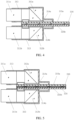
FIG. 4 is a structural diagram of an imaging module of a 3D electronic endoscope in an embodiment. -
FIG. 5 is a structural diagram of an imaging module of a 3D electronic endoscope in an embodiment. -
FIG. 6 is a structural diagram of a 3D electronic endoscope in an embodiment. - In the drawings: 10-light source, 20-light guide beam, 30-insertion portion, 31-imaging module, 311-objective lens group, 311a-first objective lens group, 311b-second objective lens group, 312-prism group, 312a-first prism group, 312b-second prism group, 313-support, 314a-first sensor, 314b-second sensor, 3141-photosensitive area, 3142-second welding portion, 315a-first flexible board, 315b-second flexible board, 316-fixation substrate, 32-long tube, 33-signal amplification circuit, 40-operation portion, 41-processing component for image signal, 50-imaging host, 60-display, 70-transmission unit, 71-cable, 72-video connection cable, 100-inspected object, 1000-imaging system for 3D electronic endoscope.
- Embodiments of this disclosure are further described in detail below in conjunction with the accompanying drawings and examples. The following embodiments are used to illustrate this disclosure but are not intended to limit the scope of this disclosure.
- In the description of the embodiments of this disclosure, it should be noted that the terms "centre", "longitudinal", "lateral", "up", "down", "front", "back", "left", "right", "vertical", "horizontal", "top", "bottom", "inside", "outside", etc., indicate orientations or positional relationships based on the orientations or positional relationships shown in the accompanying drawings, and are only for facilitating describing the embodiments of this disclosure and simplifying the description, and do not indicate or imply that the referred device or components must have a specific orientation, be constructed and operated in a specific orientation, and therefore should not be understood as a limitation on the embodiments of this disclosure. Furthermore, terms "first", "second", and "third" are used for descriptive purposes only, and should not be understood as indicating or implying relative importance. "Distal end" described in embodiments of this disclosure refers to a portion of an
insertion portion 30 of a long tube, which portion is away from anoperation portion 40, and "proximal end" described in embodiments of this disclosure refers to a portion of aninsertion portion 30 of a long tube, which portion is adjacent to theoperation portion 40. - As shown in
FIG. 1 and FIG. 2 , in an embodiment, an imaging system for 3Delectronic endoscope 1000 is provided, including alight source 10, alight guide beam 20, an electronic scope, acable 71, animaging host 50, adisplay 60 and avideo connection cable 72. - The electronic scope is an important component of the imaging system for 3D
electronic endoscope 1000, and includes aninsertion portion 30 and anoperation portion 40. Theinsertion portion 30 and theoperation portion 40 may be an integrated structure. Theinsertion portion 30 includes along tube 32, animaging module 31, an illumination optical path and atransmission unit 70. Thelong tube 32 can be a circular long tube with a relatively smooth outer surface and a hollow interior. Thelong tube 32 is inserted into a body of an inspectedobject 100, so that an outer diameter of thelong tube 32 needs to be as small as possible, such as ≤ 10.5 mm. In an embodiment, thelong tube 32 can be made into a non-circular tube, such as an elliptical tube. Theimaging module 31 is arranged inside a portion of thelong tube 32, which portion is away from theoperation portion 40, that is, theimaging module 31 is arranged at a distal end of thelong tube 32, so as to receive an image light, which is reflected or excited by a designated region of the inspectedobject 100, convert the image light into an electrical signal, and transmit the electrical signal to theoperation portion 40 through thetransmission unit 70. Specifically, theimaging module 31 of the 3D electronic endoscope has two optical paths, which are equipped with a first optical path component and a second optical path component. The first optical path component receives an image light from a left or right side, and the second optical path component receives an image light from the other side. The left image light and the right image light are respectively transmitted to two sensors 314 (that is, afirst sensor 314a, and asecond sensor 314b). In order to ensure a final three-dimensional imaging effect, two sensors of a same model are preferably used. Thefirst sensor 314a and thesecond sensor 314b respectively convert the image light along a first path and the image light along a second path obtained into a first electrical signal and a second electrical signal respectively, and transmit the first electrical signal and the second electrical signal to theoperation portion 40 through thetransmission unit 70, respectively. The illumination optical path is capable of being connected with thelight guide beam 20, and is configured to illuminate the designated region of the inspectedobject 100 with a light which is transmitted by thelight source 10. Thetransmission unit 70 is connected with theoperation portion 40, and is configured to transmit the electrical signals which are outputted by the sensors 314 to theoperation portion 40. Theoperation portion 40 includes an operation handle housing, a controller, and a processing component forimage signal 41. The controller is configured to implement different functions according to signal(s) which is(are) inputted by an operator. For example, the controller can implement functions, such as a mode conversion function, a focus function, a color correction function, a lighting switch function, etc. The processing component forimage signal 41 is configured to process the first electrical signal and the second electrical signal, which are transmitted by thetransmission unit 70, so as to obtain a first image signal and a second image signal, and transmit the first image signal and the second image signal to theimaging host 50. The processing component for image signal can perform relay processing, serial-to-parallel conversion, differential transmission processing, etc., on the received electrical signals. In another embodiment, at least some electrical signal(s) of the first image signal and/or the second image signal may be converted by at least one image signal conversion unit into non-electrical signal(s), such as optical signal(s) from electrical signal(s). - The
display 60 displays an image of the designated region of the inspectedobject 100. After the left and right image lights obtained by the 3D electronic endoscope are processed (such as polarization-processed), a corresponding image for the designated region of the inspectedobject 100 is displayed on thedisplay 60. The observer needs to wear polarized glasses for observation, and finally observes a three-dimensional stereoscopic image. - A
signal amplification circuit 33 may also be provided inside the 3D electronic endoscope. Thesignal amplification circuit 33 is provided between theimaging module 31 and the processing component forimage signal 41, and is configured to amplify the electrical signal which is outputted by theimaging module 31, so as to ensure that the electrical signal is not excessively attenuated during transmission, thereby affecting the final imaging effect. - The
imaging host 50 is connected with the 3D electronic endoscope via acable 71, and the image signal generated by the 3D electronic endoscope is transmitted to theimaging host 50 via thecable 71 for processing. In some embodiments, thecable 71 may be an optical communication cable, such as an optical fibre. The 3D electronic endoscope converts the image signal (electrical signal) into an optical signal, which is transmitted to theimaging host 50 via thecable 71. Theimaging host 50 then converts the optical signal into the electrical signal (image signal). In another embodiment, thecable 71 may also be a photoelectric composite cable. The 3D electronic endoscope converts some electrical signals into optical signals, retains some electrical signals, and transmits these signals to theimaging host 50 through thecable 71 for processing. In another embodiment, the 3D electronic endoscope can also transmit the image signal to theimaging host 50 for processing via wireless transmission. - Those skilled in the art should understand that
FIG. 1 is merely an example of an imaging system for 3D electronic endoscope and does not constitute a limitation of the imaging system for 3D electronic endoscope. The imaging system for 3D electronic endoscope may include more or fewer units than shown inFIG.1 , or combine certain units, or include different units. - In an embodiment, the
light source 10 is configured to provide illumination or excitation light source to a region to be observed. The light source includes a white light source (illumination light source). In another embodiment, thelight source 10 may also include an excitation light source (laser light source, such as near-infrared light) corresponding to a fluorescent agent. - In an embodiment, a processor is provided inside the
imaging host 50, and theimaging host 50 is connected with the electronic scope via acable 71 for obtaining an image signal which is outputted by the electronic scope. After the processor obtains the image signal which is outputted by the electronic scope, it processes the image signal to output a white light image or a fluorescent image of an observed tissue. The acquired image signal may be a separate white light signal or a fluorescent signal, or may be an image signal that is a combination of a white light signal and a fluorescent signal. - An embodiment of this disclosure provides an imaging head for 3D electronic endoscope, which imaging head can be used in the imaging system for 3D
electronic endoscope 1000 provided in any one of above embodiments. - The 3D electronic endoscope includes an
operation portion 40 and aninsertion portion 30; wherein theinsertion portion 30 and theoperation portion 40 may be an integrated structure, and together constitute an imaging head for medical endoscope. Wherein theinsertion portion 30 includes along tube 32, animaging module 31, an illumination optical path and atransmission unit 70. Thelong tube 32 is a tubular structure with a hollow interior, and theimaging module 31 is arranged inside thelong tube 32. The illumination optical path and thetransmission unit 70 are arranged inside thelong tube 32; the illumination optical path is configured to illuminate a designated region of an inspectedobject 100 with a light from alight source 10. In an embodiment, thelight source 10 and the 3D electronic endoscope are connected via alight guide beam 20. In another embodiment, thelight source 10 is arranged at a distal end of the 3D electronic endoscope. - The
imaging module 31 is configured to receive an image light which is reflected or excited by the designated region and obtained by a distal end of theinsertion portion 30, convert the image light into an electrical signal, and transmit the electrical signal to theoperation portion 40 through thetransmission unit 70. - The
operation portion 40 includes an operation handle housing, a controller and a processing component forimage signal 41; the controller is configured to implement different functions according to signal(s), which are/is inputted by an operator; the processing component for image signal is configured to process the electrical signal which is transmitted by thetransmission unit 70, so as to obtain an image signal. In another embodiment, theoperation portion 40 may further include an image signal conversion unit for converting the image signal into another non-electrical signal. - As shown in
FIG. 4 , theimaging module 31 includes a first optical path component, a second optical path component, afirst sensor 314 a, asecond sensor 314 b, a firstflexible board 315 a, a secondflexible board 315 b and afixation substrate 316. The firstflexible board 315 a and the secondflexible board 315 b function as circuit boards to transmit the electrical signal to thetransmission unit 70. As shown inFIG. 5 , in an embodiment, thefixation substrate 316 may also be composed of multiple pieces which are joined together to form a whole. In another embodiment, thefixation substrate 316 may also be a ceramic plate or a metal plate. Ceramic plate has mature manufacturing processes and is moderately priced, so is a conventional material for making medical endoscopes. Metal plate can facilitate heat conduction and guide heat from the sensor 314 to the long tube. - The first optical path component includes a first
objective lens group 311a and afirst prism group 312a, and the second optical path component includes a secondobjective lens group 311b and asecond prism group 312b. The firstobjective lens group 311a is configured to receive the image light along a first path which is reflected or excited by a designated region; thefirst prism group 312a is configured to reflect or transmit the image light along the first path to thefirst sensor 314a; thefirst sensor 314a is electrically connected with the firstflexible board 315a, and configured to convert the image light along the first path into a first electrical signal. The secondobjective lens group 311b is configured to receive the image light along a second path which is reflected or excited by the designated region; thesecond prism group 312b is configured to reflect or transmit the image light along the second path to thesecond sensor 314b; thesecond sensor 314b is electrically connected with the secondflexible board 315b, and configured to convert the image light along the second path into a second electrical signal. - The first
flexible board 315a and the secondflexible board 315b are electrically connected with thetransmission unit 70, so as to transmit the first electrical signal and the second electrical signal to thetransmission unit 70; thefirst sensor 314a and thesecond sensor 314b are respectively arranged on respective sides of thefixation substrate 316, wherein thefirst sensor 314a and the firstflexible board 315a are arranged on a same surface of thefixation substrate 316, and thesecond sensor 314b and the secondflexible board 315b are arranged on the other surface of thefixation substrate 316. A hardness or rigidity of thefixation substrate 316 is stronger than that of the firstflexible board 315 a or the secondflexible board 315 b, and provides a support force for the firstflexible board 315 a or the secondflexible board 315 b. Compared with a conventional hard board, the embodiment of this disclosure can adjust a relative position of thefirst sensor 314a or a relative position of thesecond sensor 314b, which is connected with the firstflexible board 315a or the secondflexible board 315b, by adjusting a position of the firstflexible board 315a or the secondflexible board 315b, which is more convenient to align the relative positions of thefirst sensor 314a and thesecond sensor 314b, facilitates calibration, and improves imaging quality. - In an embodiment, the sensor 314 may be a CSP sensor or a COB sensor, etc. In this disclosure, a COB sensor as shown in
FIG. 3 is preferred, because compared with the CSP sensor used in conventional medical endoscopes, the COB sensor is smaller and thinner, and uses gold wire for welding, while the CSP sensor is larger and welded through a bottom welding ball. Using a COB sensor can effectively reduce a volume required for arranging the sensor 314, leave more space for the optical lens group, thereby maximizing the optical lens group and acquiring more image light. Asecond welding portion 3142 is arranged around the sensor, and a first welding portion which corresponds to thesecond welding portion 3142 is arranged on the flexible board. The first welding portion and thesecond welding portion 3142 are welded together, so as to realize electrical connection between the flexible board and the sensor. - The
imaging module 31 is an important component of the imaging head for the endoscope to image. The larger theimaging module 31 is, the more light signals theimaging module 31 can receive, thereby presenting a high-quality observation image. However, since theimaging module 31 is arranged inside thelong tube 32 and is limited by a diameter of thelong tube 32, the space in which theimaging module 31 can be arranged is limited. The embodiments of this disclosure maximize a photosensitive area and ensure an imaging quality by reasonably arranging internal structure(s) for component(s) of theimaging module 31. - In an embodiment, the
first sensor 314a, the firstflexible board 315a, thefixation substrate 316, the secondflexible board 315b and thesecond sensor 314b are stacked, and positions of these elements can be arranged in a straight line or be stacked in a staggered manner. - In an embodiment, the first
flexible board 315a is provided with a through-hole structure, wherein thefirst sensor 314a is arranged inside said through-hole structure; and/or the secondflexible board 315b is provided with a through-hole structure, wherein thesecond sensor 314b is arranged inside said through-hole structure. A metal plate or a substrate made of other materials may be arranged inside the through-hole structure, so as to provide a support force for the sensor arranged inside the through-hole structure. - In an embodiment, the
first prism group 312a includes right-angle prism(s) or triangular prism(s); and/or thesecond prism group 312b includes right-angle prism(s) or triangular prism(s). A number of prism(s) in thefirst prism group 312a and thesecond prism group 312b is not limited, and can be one or more. - In an embodiment, a light-exiting end surface of the
first prism group 312a is a rectangle, a long side of said rectangle is parallel to an axial direction of the long tube, and a short side of said rectangle is perpendicular to the axial direction of the long tube; and/or a light-exiting end surface of thesecond prism group 312b is a rectangle, a long side of said rectangle is parallel to an axial direction of the long tube, and a short side of said rectangle is perpendicular to the axial direction of the long tube. In a special embodiment, the long side is equal to the short side, that is, the light-exiting end surface is a square. In another embodiment, the long side of the light-exiting end surface is longer than the short side. In an embodiment, short side(s) of prism(s) in thefirst prism group 312a and/or thesecond prism group 312b is(are) greater than or equal to height(s) of said prism(s), long side(s) of said prism(s) is(are) greater than or equal to short side(s) of said prism(s). In this way, the height of the prism can be fully utilized to maximize the effective image surface, thereby outputting an image of higher resolution. The short side(s) of the prism(s) is(are) less than or equal to the long side(s) of the prism(s), which is also to ensure that the reflective surface of the prism group is fully utilized, so as to output as much image light as possible to achieve a higher resolution output. - In an embodiment, diaphragm(s) may be further added on the light-exiting end surface of the
first prism group 312a and/or thesecond prism group 312b. The diaphragm(s) is(are) arranged on the light-exiting end surface of thefirst prism group 312a and/or thesecond prism group 312b, such that the diaphragm(s) block(s) some image lights that cannot be transmitted to thephotosensitive area 3141, thereby preventing mutual interference between lights, preventing influence on the accuracy of the sensor 314, and preventing glare, ghosting, etc., which affect the imaging effect. - In an embodiment, a
photosensitive area 3141 on a photosensitive surface of thefirst sensor 314a is greater than or equal to the light-exiting end surface of thefirst prism group 312a; and/or aphotosensitive area 3141 on a photosensitive surface of thesecond sensor 314b is greater than or equal to the light-exiting end surface of thesecond prism group 312b. To ensure the imaging effect, the sensor needs to receive as more light signals as possible. - In an embodiment, the light-exiting end surface of the
first prism group 312a is arranged on the photosensitive surface of thefirst sensor 314a, and at least part of thephotosensitive area 3141 of thefirst sensor 314a is in a closed space; and/or the light-exiting end surface of thesecond prism group 312b is arranged on the photosensitive surface of thesecond sensor 314b, and at least part of thephotosensitive area 3141 of thesecond sensor 314b is in a closed space, so as to prevent dust and other debris from adhering to or falling into thephotosensitive area 3141 of the sensor, thereby ensuring the effectiveness. In another embodiment, a glass plate may also be used and arranged between thefirst prism group 312a and thefirst sensor 314a; and/or the glass plate may be arranged between thesecond prism group 312b and thesecond sensor 314b. In another embodiment, other polymer transparent plate, such as a plastic plate, etc., may also be used. - As shown in
FIG. 2 , in an embodiment, thetransmission unit 70 includes asignal amplification circuit 33, which is configured to amplify the acquired first electrical signal and/or second electrical signal, and transmit the amplified signal(s) to the processing component forimage signal 41, so as to prevent the image signal from being excessively attenuated during the transmission process and thus causing the electrical signal strength received by the processing component forimage signal 41 to be too weak to affect the imaging quality. - In an embodiment, a
support 313 is further included, and the first optical path component and the second optical path component are arranged at thesupport 313. - In an embodiment, a 3D electronic endoscope includes an
operation portion 40 and aninsertion portion 30; wherein theinsertion portion 30 and theoperation portion 40 may be an integrated structure, and together constitute an imaging head for medical endoscope. Wherein theinsertion portion 30 includes along tube 32, animaging module 31, an illumination optical path and atransmission unit 70; wherein thelong tube 32 is a tubular structure with a hollow interior, and theimaging module 31 is arranged inside thelong tube 32. The illumination optical path and thetransmission unit 70 are arranged inside thelong tube 32; the illumination optical path is configured to illuminate a designated region of an inspectedobject 100 with a light from alight source 10. - The
imaging module 31 is configured to receive an image light which is reflected or excited by a designated region and obtained by a distal end of theinsertion portion 30, convert the image light into an electrical signal, and transmit the electrical signal to theoperation portion 40 through thetransmission unit 70. - The
operation portion 40 includes an operation handle housing, a controller and a processing component forimage signal 41; wherein the controller is configured to implement different functions according to signal(s), which is(are) inputted by an operator; the processing component for image signal is configured to process the electrical signal which is transmitted by thetransmission unit 70, so as to obtain an image signal. - The
imaging module 31 includes an optical path component, a sensor, a flexible board, and afixation substrate 316. - The optical path component includes an objective lens group and a prism group; wherein the objective lens group is configured to receive the image light which is reflected or excited by the designated region; the prism group is configured to reflect or transmit the image light to the sensor; the sensor is electrically connected with the flexible board, and configured to convert the image light into the electrical signal.
- The flexible board is electrically connected with the
transmission unit 70, so as to transmit the electrical signal to thetransmission unit 70; one sensor is respectively arranged on one respective side of thefixation substrate 316, wherein the sensor and the flexible board are arranged on a same surface of thefixation substrate 316. A hardness or rigidity of thefixation substrate 316 is greater than that of the flexible board, so as to provide a support force for the flexible board. - The above specific examples are used to illustrate this disclosure, which are only used to help understand this disclosure and are not intended to limit this disclosure.
Claims (16)
- A 3D electronic endoscope, characterized in that, comprising an insertion portion and an operation portion;wherein the insertion portion comprises a long tube, an imaging module, an illumination optical path, and a transmission unit; the long tube is a tubular structure with a hollow interior, the imaging module is arranged inside the long tube, the illumination optical path and the transmission unit are also arranged inside the long tube; the illumination optical path is configured to illuminate a designated region of an inspected object with a light; the imaging module is configured to receive an image light which is reflected or excited by the designated region and obtained by a distal end of the insertion portion, convert the image light into an electrical signal, and transmit the electrical signal to the operation portion through the transmission unit;wherein the operation portion comprises an operation handle housing, a controller, and a processing component for image signal; the controller and the processing component for image signal are arranged inside the operation handle housing; the controller is configured to implement different functions according to signal(s) which is(are) inputted by an operator; the processing component for image signal is configured to process the electrical signal which is transmitted by the transmission unit, so as to obtain an image signal;wherein the imaging module comprises a first optical path component, a second optical path component, a first sensor, a second sensor, a first flexible board, a second flexible board, and a fixation substrate; the first optical path component comprises a first objective lens group and a first prism group, the second optical path component comprises a second objective lens group and a second prism group; the first objective lens group is configured to receive the image light along a first path which is reflected or excited by the designated region, the first prism group is configured to reflect or transmit the image light along the first path to the first sensor; the first sensor is electrically connected with the first flexible board, and configured to convert the image light along the first path into a first electrical signal; the second objective lens group is configured to receive the image light along a second path which is reflected or excited by the designated region; the second prism group is configured to reflect or transmit the image light along the second path to the second sensor; the second sensor is electrically connected with the second flexible board, and configured to convert the image light along the second path into a second electrical signal;the first flexible board and the second flexible board are electrically connected with the transmission unit, so as to transmit the first electrical signal and the second electrical signal to the transmission unit;the first sensor and the second sensor are arranged on respective sides of the fixation substrate; the first sensor and the first flexible board are arranged on one surface of the fixation substrate; the second sensor and the second flexible board are arranged on the other surface of the fixation substrate.
- The 3D electronic endoscope according to claim 1, characterized in that, the first sensor, the first flexible board, the fixation substrate, the second flexible board and the second sensor are stacked.
- The 3D electronic endoscope according to claim 1, characterized in that, the first flexible board is provided with a through-hole structure, wherein the first sensor is arranged inside said through-hole structure; and/or
the second flexible board is provided with a through-hole structure, wherein the second sensor is arranged inside said through-hole structure. - The 3D electronic endoscope according to claim 1, characterized in that, the first prism group comprises right-angle prism(s) or triangular prism(s); and/or
the second prism group comprises right-angle prism(s) or triangular prism(s). - The 3D electronic endoscope according to claim 1, characterized in that, a light-exiting end surface of the first prism group is a rectangle; wherein a long side of said rectangle is parallel to an axial direction of the long tube, and a short side of said rectangle is perpendicular to the axial direction of the long tube; and/or
a light-exiting end surface of the second prism group is a rectangle; wherein a long side of said rectangle is parallel to an axial direction of the long tube, and a short side of said rectangle is perpendicular to the axial direction of the long tube. - The 3D electronic endoscope according to claim 1, characterized in that, further comprising diaphragm(s), which is(are) arranged on a light-exiting end surface of the first prism group and/or a light-exiting end surface of the second prism group.
- The 3D electronic endoscope according to claim 1, characterized in that, a photosensitive area on a photosensitive surface of the first sensor is greater than or equal to a light-exiting end surface of the first prism group; and/or
a photosensitive area on a photosensitive surface of the second sensor is greater than or equal to a light-exiting end surface of the second prism group. - The 3D electronic endoscope according to claim 7, characterized in that, the light-exiting end surface of the first prism group is arranged on the photosensitive surface of the first sensor, and at least part of the photosensitive area on the photosensitive surface of the first sensor is in a closed space; and/or
the light-exiting end surface of the second prism group is arranged on the photosensitive surface of the second sensor, and at least part of the photosensitive area on the photosensitive surface of the second sensor is in a closed space. - The 3D electronic endoscope according to claim 1, characterized in that, further comprising glass plate(s), which is(are) arranged between the first prism group and the first sensor, and/or between the second prism group and the second sensor.
- The 3D electronic endoscope according to claim 1, characterized in that, the transmission unit comprises a signal amplification circuit, which is configured to amplify the first electrical signal and/or the second electrical signal, and transmit the amplified signal(s) to the processing component for image signal.
- The 3D electronic endoscope according to claim 1, characterized in that, the fixation substrate comprises a first fixation substrate and a second fixation substrate; wherein the first sensor and the first flexible board are arranged on the first fixation substrate; the second sensor and the second flexible board are arranged on the second fixation substrate.
- The 3D electronic endoscope according to any one of claims 1-11, characterized in that, the fixation substrate is a heat conduction plate for conducting heat which is generated by the sensor(s).
- The 3D electronic endoscope according to any one of claims 1-12, characterized in that, the fixation substrate is a ceramic plate or a metal plate.
- The 3D electronic endoscope according to claim 1, characterized in that, further comprising a support; wherein the first optical path component and the second optical path component are arranged at the support.
- A 3D electronic endoscope assembly, characterized in that, comprising an insertion portion and an operation portion;wherein the insertion portion comprises a long tube, an imaging module, an illumination optical path, and a transmission unit; the long tube is a tubular structure with a hollow interior, the imaging module is arranged inside the long tube, the illumination optical path and the transmission unit are also arranged inside the long tube; the illumination optical path is configured to illuminate a designated region of an inspected object with a light; the imaging module is configured to receive an image light which is reflected or excited by the designated region and obtained by a distal end of the insertion portion, convert the image light into an electrical signal, and transmit the electrical signal to the operation portion through the transmission unit;wherein the operation portion comprises an operation handle housing, a controller, and a processing component for image signal; the controller and the processing component for image signal are arranged inside the operation handle housing; the controller is configured to implement different functions according to signal(s) which is(are) inputted by an operator; the processing component for image signal is configured to process the electrical signal which is transmitted by the transmission unit, so as to obtain an image signal;wherein the imaging module comprises an objective lens group, a prism group, a sensor, a fixation substrate, and a flexible board; wherein the objective lens group is configured to receive the image light which is reflected or excited by the designated region; the prism group is configured to reflect or transmit to the sensor the image light which is received by the objective lens group; wherein the sensor is electrically connected with the flexible board, and configured to convert the image light into the electrical signal; the flexible board is electrically connected with the transmission unit, and configured to transmit the electrical signal to the transmission unit;the sensor and the flexible board are electrically connected with each other, wherein the sensor and the flexible board are arranged on the fixation substrate.
- An imaging system for 3D electronic endoscope, characterized in that, comprising a light source, a light guide beam, an imaging host, a cable, and the 3D electronic endoscope according to any one of claims 1-14; wherein the light source is connected with the 3D electronic endoscope through the light guide beam, and one end of the 3D electronic endoscope is connected with the imaging host through the cable.
Applications Claiming Priority (2)
| Application Number | Priority Date | Filing Date | Title |
|---|---|---|---|
| CN202220402386 | 2022-02-24 | ||
| PCT/CN2022/103722 WO2023159851A1 (en) | 2022-02-24 | 2022-07-04 | 3d electronic endoscope and camera system therefor |
Publications (2)
| Publication Number | Publication Date |
|---|---|
| EP4480386A1 true EP4480386A1 (en) | 2024-12-25 |
| EP4480386A4 EP4480386A4 (en) | 2025-06-11 |
Family
ID=83258573
Family Applications (1)
| Application Number | Title | Priority Date | Filing Date |
|---|---|---|---|
| EP22928120.9A Pending EP4480386A4 (en) | 2022-02-24 | 2022-07-04 | 3d electronic endoscope and camera system therefor |
Country Status (4)
| Country | Link |
|---|---|
| US (1) | US20240407629A1 (en) |
| EP (1) | EP4480386A4 (en) |
| CN (6) | CN217960050U (en) |
| WO (1) | WO2023159851A1 (en) |
Families Citing this family (4)
| Publication number | Priority date | Publication date | Assignee | Title |
|---|---|---|---|---|
| CN217960050U (en) * | 2022-02-24 | 2022-12-06 | 深圳迈瑞生物医疗电子股份有限公司 | 3D electronic endoscope and camera system thereof |
| CN116841032B (en) * | 2023-05-31 | 2024-06-04 | 极限人工智能有限公司 | Endoscope lens, electronic endoscope and image acquisition method |
| CN119014784A (en) * | 2024-08-06 | 2024-11-26 | 山东威高手术机器人有限公司 | Signal transmission method, device, electronic device and computer readable storage medium |
| CN119632482A (en) * | 2024-12-31 | 2025-03-18 | 浙江华诺康科技有限公司 | Camera module and electronic endoscope |
Family Cites Families (12)
| Publication number | Priority date | Publication date | Assignee | Title |
|---|---|---|---|---|
| US4622954A (en) * | 1984-05-15 | 1986-11-18 | Fuji Photo Optical Co., Ltd. | Endoscope having a plate-like image sensor for forming images |
| WO2003098913A2 (en) * | 2002-05-16 | 2003-11-27 | Cbyond Inc. | Miniature camera head |
| US8814779B2 (en) * | 2006-12-21 | 2014-08-26 | Intuitive Surgical Operations, Inc. | Stereoscopic endoscope |
| WO2009090667A1 (en) * | 2008-01-18 | 2009-07-23 | Johnson & Johnson Limited | Portable imaging device |
| US8672838B2 (en) * | 2011-08-12 | 2014-03-18 | Intuitive Surgical Operations, Inc. | Image capture unit in a surgical instrument |
| US9107573B2 (en) * | 2012-10-17 | 2015-08-18 | Karl Storz Endovision, Inc. | Detachable shaft flexible endoscope |
| CN105708408A (en) * | 2016-01-04 | 2016-06-29 | 卓外(上海)医疗电子科技有限公司 | Handheld full-high-definition minimally invasive surgery 3D electronic endoscopy system |
| WO2017169822A1 (en) * | 2016-03-30 | 2017-10-05 | ソニー株式会社 | Solid-state image capturing element, image capturing device, endoscope device, and electronic instrument |
| JP6630639B2 (en) * | 2016-07-11 | 2020-01-15 | 富士フイルム株式会社 | Endoscope |
| JP7034308B2 (en) * | 2018-09-06 | 2022-03-11 | オリンパス株式会社 | Light source control device, endoscope system, and dimming control method |
| CN110537893A (en) * | 2019-10-09 | 2019-12-06 | 南京速瑞医疗科技有限公司 | Soft 3D Electronic Endoscopy System |
| CN217960050U (en) * | 2022-02-24 | 2022-12-06 | 深圳迈瑞生物医疗电子股份有限公司 | 3D electronic endoscope and camera system thereof |
-
2022
- 2022-04-08 CN CN202220817327.8U patent/CN217960050U/en active Active
- 2022-07-04 CN CN202210788022.3A patent/CN115067864A/en active Pending
- 2022-07-04 EP EP22928120.9A patent/EP4480386A4/en active Pending
- 2022-07-04 CN CN202210787512.1A patent/CN115251810A/en active Pending
- 2022-07-04 CN CN202221730023.4U patent/CN219126270U/en active Active
- 2022-07-04 WO PCT/CN2022/103722 patent/WO2023159851A1/en not_active Ceased
- 2022-07-04 CN CN202221729091.9U patent/CN218684313U/en active Active
- 2022-11-22 CN CN202211467494.5A patent/CN115736793A/en active Pending
-
2024
- 2024-08-22 US US18/811,969 patent/US20240407629A1/en active Pending
Also Published As
| Publication number | Publication date |
|---|---|
| US20240407629A1 (en) | 2024-12-12 |
| CN217960050U (en) | 2022-12-06 |
| CN219126270U (en) | 2023-06-06 |
| CN115251810A (en) | 2022-11-01 |
| WO2023159851A1 (en) | 2023-08-31 |
| CN115067864A (en) | 2022-09-20 |
| CN218684313U (en) | 2023-03-24 |
| EP4480386A4 (en) | 2025-06-11 |
| CN115736793A (en) | 2023-03-07 |
Similar Documents
| Publication | Publication Date | Title |
|---|---|---|
| US20240407629A1 (en) | 3d electronic endoscope and imaging system thereof | |
| US8823788B2 (en) | Imaging apparatus | |
| US7976459B2 (en) | Portable endoscope for intubation | |
| US7108657B2 (en) | Endoscopic visualization apparatus with different imaging systems | |
| JP5704878B2 (en) | Photoelectric conversion connector, optical transmission module, imaging device, and endoscope | |
| US4600940A (en) | Video camera for use with an endoscope and method for making same | |
| RU2770743C1 (en) | Electronic endoscope and electronic endoscope system | |
| JP7227011B2 (en) | Endoscope | |
| US10084947B2 (en) | Imaging module | |
| US20090118580A1 (en) | Image-type intubation-aiding device | |
| RU2010134430A (en) | ERGONOMIC HAND CAMERA FOR ENDOSCOPIC IMAGE FORMER | |
| US20200110257A1 (en) | Imaging unit and endoscope | |
| US4600939A (en) | Focusable video camera for use with endoscopes | |
| US20210196110A1 (en) | Electronic video laser endoscope | |
| JPH0820603B2 (en) | Video scope equipment | |
| US4600938A (en) | Focusable video camera for use with endoscopes | |
| CN217960035U (en) | Endoscopic device with wide-angle imaging and surgical robotic system | |
| KR100369287B1 (en) | vision system for diagnosis | |
| JP3791763B2 (en) | Endoscope | |
| JP3714636B2 (en) | Endoscope device | |
| CN119632482A (en) | Camera module and electronic endoscope | |
| CN101112301A (en) | Snake-shaped wireless electronic endoscope | |
| CN221865602U (en) | Endoscope optical system and endoscope system | |
| JP2006288821A (en) | Electronic endoscope | |
| KR200215296Y1 (en) | vision system for diagnosis |
Legal Events
| Date | Code | Title | Description |
|---|---|---|---|
| STAA | Information on the status of an ep patent application or granted ep patent |
Free format text: STATUS: THE INTERNATIONAL PUBLICATION HAS BEEN MADE |
|
| PUAI | Public reference made under article 153(3) epc to a published international application that has entered the european phase |
Free format text: ORIGINAL CODE: 0009012 |
|
| STAA | Information on the status of an ep patent application or granted ep patent |
Free format text: STATUS: REQUEST FOR EXAMINATION WAS MADE |
|
| 17P | Request for examination filed |
Effective date: 20240920 |
|
| AK | Designated contracting states |
Kind code of ref document: A1 Designated state(s): AL AT BE BG CH CY CZ DE DK EE ES FI FR GB GR HR HU IE IS IT LI LT LU LV MC MK MT NL NO PL PT RO RS SE SI SK SM TR |
|
| DAV | Request for validation of the european patent (deleted) | ||
| DAX | Request for extension of the european patent (deleted) | ||
| A4 | Supplementary search report drawn up and despatched |
Effective date: 20250513 |
|
| RIC1 | Information provided on ipc code assigned before grant |
Ipc: H04N 23/50 20230101ALI20250507BHEP Ipc: G02B 23/24 20060101ALI20250507BHEP Ipc: A61B 1/00 20060101ALI20250507BHEP Ipc: A61B 1/05 20060101AFI20250507BHEP |
|
| RAP1 | Party data changed (applicant data changed or rights of an application transferred) |
Owner name: WUHAN MINDRAY SCIENTIFIC CO., LTD. Owner name: SHENZHEN MINDRAY BIO-MEDICAL ELECTRONICS CO., LTD. |