EP4479210B1 - Kalibriersystem und kalibrierverfahren zur kalibrierung eines bauplattformsystems in einer additiven fertigungsvorrichtung - Google Patents
Kalibriersystem und kalibrierverfahren zur kalibrierung eines bauplattformsystems in einer additiven fertigungsvorrichtung Download PDFInfo
- Publication number
- EP4479210B1 EP4479210B1 EP23805459.7A EP23805459A EP4479210B1 EP 4479210 B1 EP4479210 B1 EP 4479210B1 EP 23805459 A EP23805459 A EP 23805459A EP 4479210 B1 EP4479210 B1 EP 4479210B1
- Authority
- EP
- European Patent Office
- Prior art keywords
- calibration
- additive manufacturing
- plate
- calibration plate
- platform system
- Prior art date
- Legal status (The legal status is an assumption and is not a legal conclusion. Google has not performed a legal analysis and makes no representation as to the accuracy of the status listed.)
- Active
Links
Images


Classifications
-
- B—PERFORMING OPERATIONS; TRANSPORTING
- B22—CASTING; POWDER METALLURGY
- B22F—WORKING METALLIC POWDER; MANUFACTURE OF ARTICLES FROM METALLIC POWDER; MAKING METALLIC POWDER; APPARATUS OR DEVICES SPECIALLY ADAPTED FOR METALLIC POWDER
- B22F12/00—Apparatus or devices specially adapted for additive manufacturing; Auxiliary means for additive manufacturing; Combinations of additive manufacturing apparatus or devices with other processing apparatus or devices
- B22F12/30—Platforms or substrates
-
- B—PERFORMING OPERATIONS; TRANSPORTING
- B22—CASTING; POWDER METALLURGY
- B22F—WORKING METALLIC POWDER; MANUFACTURE OF ARTICLES FROM METALLIC POWDER; MAKING METALLIC POWDER; APPARATUS OR DEVICES SPECIALLY ADAPTED FOR METALLIC POWDER
- B22F10/00—Additive manufacturing of workpieces or articles from metallic powder
- B22F10/20—Direct sintering or melting
- B22F10/28—Powder bed fusion, e.g. selective laser melting [SLM] or electron beam melting [EBM]
-
- B—PERFORMING OPERATIONS; TRANSPORTING
- B22—CASTING; POWDER METALLURGY
- B22F—WORKING METALLIC POWDER; MANUFACTURE OF ARTICLES FROM METALLIC POWDER; MAKING METALLIC POWDER; APPARATUS OR DEVICES SPECIALLY ADAPTED FOR METALLIC POWDER
- B22F10/00—Additive manufacturing of workpieces or articles from metallic powder
- B22F10/30—Process control
- B22F10/31—Calibration of process steps or apparatus settings, e.g. before or during manufacturing
-
- B—PERFORMING OPERATIONS; TRANSPORTING
- B22—CASTING; POWDER METALLURGY
- B22F—WORKING METALLIC POWDER; MANUFACTURE OF ARTICLES FROM METALLIC POWDER; MAKING METALLIC POWDER; APPARATUS OR DEVICES SPECIALLY ADAPTED FOR METALLIC POWDER
- B22F12/00—Apparatus or devices specially adapted for additive manufacturing; Auxiliary means for additive manufacturing; Combinations of additive manufacturing apparatus or devices with other processing apparatus or devices
- B22F12/90—Means for process control, e.g. cameras or sensors
-
- B—PERFORMING OPERATIONS; TRANSPORTING
- B22—CASTING; POWDER METALLURGY
- B22F—WORKING METALLIC POWDER; MANUFACTURE OF ARTICLES FROM METALLIC POWDER; MAKING METALLIC POWDER; APPARATUS OR DEVICES SPECIALLY ADAPTED FOR METALLIC POWDER
- B22F7/00—Manufacture of composite layers, workpieces, or articles, comprising metallic powder, by sintering the powder, with or without compacting wherein at least one part is obtained by sintering or compression
- B22F7/06—Manufacture of composite layers, workpieces, or articles, comprising metallic powder, by sintering the powder, with or without compacting wherein at least one part is obtained by sintering or compression of composite workpieces or articles from parts, e.g. to form tipped tools
- B22F7/08—Manufacture of composite layers, workpieces, or articles, comprising metallic powder, by sintering the powder, with or without compacting wherein at least one part is obtained by sintering or compression of composite workpieces or articles from parts, e.g. to form tipped tools with one or more parts not made from powder
-
- B—PERFORMING OPERATIONS; TRANSPORTING
- B23—MACHINE TOOLS; METAL-WORKING NOT OTHERWISE PROVIDED FOR
- B23Q—DETAILS, COMPONENTS, OR ACCESSORIES FOR MACHINE TOOLS, e.g. ARRANGEMENTS FOR COPYING OR CONTROLLING; MACHINE TOOLS IN GENERAL CHARACTERISED BY THE CONSTRUCTION OF PARTICULAR DETAILS OR COMPONENTS; COMBINATIONS OR ASSOCIATIONS OF METAL-WORKING MACHINES, NOT DIRECTED TO A PARTICULAR RESULT
- B23Q1/00—Members which are comprised in the general build-up of a form of machine, particularly relatively large fixed members
- B23Q1/0063—Connecting non-slidable parts of machine tools to each other
- B23Q1/0072—Connecting non-slidable parts of machine tools to each other using a clamping opening for receiving an insertion bolt or nipple
-
- B—PERFORMING OPERATIONS; TRANSPORTING
- B33—ADDITIVE MANUFACTURING TECHNOLOGY
- B33Y—ADDITIVE MANUFACTURING, i.e. MANUFACTURING OF THREE-DIMENSIONAL [3D] OBJECTS BY ADDITIVE DEPOSITION, ADDITIVE AGGLOMERATION OR ADDITIVE LAYERING, e.g. BY 3D PRINTING, STEREOLITHOGRAPHY OR SELECTIVE LASER SINTERING
- B33Y10/00—Processes of additive manufacturing
-
- B—PERFORMING OPERATIONS; TRANSPORTING
- B33—ADDITIVE MANUFACTURING TECHNOLOGY
- B33Y—ADDITIVE MANUFACTURING, i.e. MANUFACTURING OF THREE-DIMENSIONAL [3D] OBJECTS BY ADDITIVE DEPOSITION, ADDITIVE AGGLOMERATION OR ADDITIVE LAYERING, e.g. BY 3D PRINTING, STEREOLITHOGRAPHY OR SELECTIVE LASER SINTERING
- B33Y30/00—Apparatus for additive manufacturing; Details thereof or accessories therefor
-
- B—PERFORMING OPERATIONS; TRANSPORTING
- B33—ADDITIVE MANUFACTURING TECHNOLOGY
- B33Y—ADDITIVE MANUFACTURING, i.e. MANUFACTURING OF THREE-DIMENSIONAL [3D] OBJECTS BY ADDITIVE DEPOSITION, ADDITIVE AGGLOMERATION OR ADDITIVE LAYERING, e.g. BY 3D PRINTING, STEREOLITHOGRAPHY OR SELECTIVE LASER SINTERING
- B33Y50/00—Data acquisition or data processing for additive manufacturing
- B33Y50/02—Data acquisition or data processing for additive manufacturing for controlling or regulating additive manufacturing processes
-
- Y—GENERAL TAGGING OF NEW TECHNOLOGICAL DEVELOPMENTS; GENERAL TAGGING OF CROSS-SECTIONAL TECHNOLOGIES SPANNING OVER SEVERAL SECTIONS OF THE IPC; TECHNICAL SUBJECTS COVERED BY FORMER USPC CROSS-REFERENCE ART COLLECTIONS [XRACs] AND DIGESTS
- Y02—TECHNOLOGIES OR APPLICATIONS FOR MITIGATION OR ADAPTATION AGAINST CLIMATE CHANGE
- Y02P—CLIMATE CHANGE MITIGATION TECHNOLOGIES IN THE PRODUCTION OR PROCESSING OF GOODS
- Y02P10/00—Technologies related to metal processing
- Y02P10/25—Process efficiency
Definitions
- the invention relates to a calibration system and a calibration method for calibrating a build platform system arranged in a build space of a laser-based additive manufacturing device.
- Preferred areas of application for the calibration system and the calibration method are hybrid additive manufacturing of new parts and the repair of conventionally or additively manufactured components.
- Additive manufacturing processes such as powder bed-based selective laser melting (LPBF) are primarily designed for the near-net-shape production of completely new parts: Based on a virtual 3D component model, material is consolidated layer by layer on a build platform of the additive manufacturing device until the component mold defined by the 3D model is complete.
- the starting material for the production of high-quality, metallic components using powder bed-based selective laser melting is usually a tightly specified and therefore cost-intensive metal powder, which, however, is only melted to a fraction to form the additively manufactured component. The majority of the powder serves merely as filler and support material.
- additive manufacturing of metallic components using selective laser melting is still sometimes unprofitable compared to traditional manufacturing processes in many industries due to long production times, insufficiently known material data, and high powder consumption.
- additive manufacturing has already established itself in the production of high-cost, geometrically complex, or customized components, particularly those in the aerospace and medical technology sectors.
- additive manufacturing offers the possibility of near-net-shape repairs of components.
- parts of rotor blades or guide vanes are repaired by additively building up the worn material.
- Additive manufacturing in which material is applied to existing components or component elements in a near-net-shape, is also referred to as hybrid (additive) manufacturing. Unlike complete manufacturing, hybrid manufacturing requires precise positioning of the components within the manufacturing device and precise knowledge of the component position on the build platform.
- the build platform is generally the component of the additive manufacturing device on which the components are manufactured.
- the entirety of all device components of the additive manufacturing device that support the components to be manufactured is referred to as the build platform system; a build platform in the narrower sense is understood to be the usually plate-shaped device element to which the additively manufactured components are directly attached.
- the build platform system therefore comprises at least the build platform; in its simplest structural design, the build platform system is limited to the build platform.
- the challenge in hybrid additive manufacturing is that the laser (more precisely the laser scanner) is controlled in a separate coordinate system, the laser coordinate system.
- the geometric data of the build platform system and any base moldings present on it are transferred to the laser control unit before the additive manufacturing process begins, i.e., into the laser coordinate system.
- the laser coordinate system is independent of the coordinate system used to define the actual position of the build platform system and the position of the base moldings already present on the build platform system in the build space.
- the latter coordinate system is referred to as the build space coordinate system.
- the laser does not always hit the base molded body with sufficient precision at a specific position in the build space.
- a deviation also called an offset, can occur between the build space coordinates in the build platform coordinate system and the laser coordinates in the laser coordinate system.
- the build space coordinates can be corrected with a correction value and this corrected position information of the build platform system and the base mold body can be transferred to the laser coordinate system.
- the correction values for the build space coordinates can, in turn, be determined by a calibration performed within the additive manufacturing device.
- Calibration methods used for this purpose are usually based on photographic image capture of patterns and reference markings. Such calibration methods—and the calibration devices or systems used for them—are known, among other things, from EP 0 792 481 B1 , DE 199 18 631 A1 , US 6 483 596 B1 , WO 2017/158327 A1 or DE 10 2021 105 918 A1 .
- WO 2017/158327 A1 A calibration process is described in which a calibration pattern is introduced into an aluminum plate using the laser of the additive manufacturing device.
- EP 4 151 342 A1 further discloses a manufacturing system for the additive manufacturing of a workpiece, wherein the manufacturing system comprises, among other things, a build plate and an optical device for capturing image data of the build plate.
- WO 2020/ 212 108 A1 describes a calibration procedure for a camera intended to monitor an additive manufacturing process, whereby an additively manufactured component is compared with a sample of this component to calibrate the camera.
- US 2020/215759 A1 discloses a kit for calibrating a head system of a radiation source of an additive manufacturing device, which Calibration plate with multiple reference marks and a focal holder made of at least one material sensitive to the radiation of the source.
- the object of the invention is to provide a calibration system and a calibration method for calibrating a build platform system arranged in a build space of an additive manufacturing device, which enables precise material build-up in laser-based hybrid additive manufacturing of components without requiring intervention in the machine control system.
- the calibration system described below and the calibration method performed with it are used to calibrate a build platform system arranged in a build chamber of an additive manufacturing device.
- the additive manufacturing device has a controllable laser for consolidating material on the build platform system during additive manufacturing.
- the build chamber is located in a build shaft in which the build platform system is usually installed in a height-adjustable manner.
- the position of the build platform system in the build space - just like all other objects in the build space - is defined by build space coordinates within a build space coordinate system.
- the position of the base mold is also described by these build space coordinates within the build space coordinate system.
- the build space coordinates are transferred to a control unit of the additive manufacturing device intended to control the laser.
- the calibration of the build platform system described below is based on the fact that the known build space coordinates intended for controlling the laser, generated for example from computer models or from preliminary measurements outside the manufacturing device, are transferred to the control unit of the additive manufacturing device together with a correction value or correction factor for each individual build space coordinate so that the laser can accurately hit the intended actual position within the build space.
- the proposed calibration system comprises an optical module and a calibration plate which can be fixed on the construction platform system and consists of a predetermined, preferably metallic, base material.
- the optics module comprises an optical detection unit, an optics holder, and a support plate for covering the build space of the additive manufacturing device.
- the support plate has a light passage recess, in the area of which the optical detection unit is fastened by means of the optics holder so that the calibration plate placed in the build space can be optically detected.
- the optical detection unit is usually located on the side of the support plate opposite the build space.
- the optical axis of the optical detection unit is preferably aligned perpendicular to the support plate.
- the optical detection unit can be, for example, a camera or a - preferably high-resolution - stripe light projection unit.
- light sources for illuminating the installation space are attached to the support plate, for example in the form of light-emitting diodes, which are preferably arranged evenly distributed on the installation space side of the support plate.
- the calibration plate has a visible surface on one of its two flat sides, which, when the calibration system is configured as intended, faces the optical detection unit.
- the visible surface of the calibration plate is provided with a surface layer that contrasts with the specified base material in color, i.e., the surface layer has a clear color contrast to the color of the specified base material.
- the surface layer is preferably dark, for example, black, while the uncoated base material has a light appearance (often a silvery-metallic appearance in the case of a metallic base material).
- the calibration system can further comprise one or more reference mark carriers, each with a reference mark.
- These reference mark carriers can be precisely fixed to the build platform system; they serve as reference points on the build platform system fixed in the additive manufacturing device. To ensure the optical detection unit's view of the reference marks, reference mark recesses can be incorporated into the calibration plate.
- the calibration method according to the invention for calibrating the build platform system that is properly mounted in the build space of the laser-based additive manufacturing device is carried out with the calibration system described above, which comprises the optics module, the calibration plate and the reference mark carriers provided with the reference markings, and with an evaluation unit for evaluating position parameters and for determining the above-mentioned correction values.
- the calibration plate and the reference mark carriers are fixed in such a way that the visible surface and the reference marks are visible simultaneously when viewed from above on the visible surface of the calibration plate.
- a calibration pattern consisting of two-dimensional pattern elements is created in the visible surface plane of the calibration plate using the laser of the additive manufacturing device.
- the position of the individual pattern elements is defined by target position parameters that are stored in a computer model and transferred to the control unit of the additive manufacturing device in the form of the build space coordinates.
- the calibration pattern is produced based on the target position parameters and is subsequently recorded in the form of actual position parameters.
- the evaluation unit is set up to determine the correction values for the build space coordinates based on a target-actual comparison of the specified target position parameters and the recorded actual position parameters, taking into account and in relation to the reference markings attached to the build platform system.
- the mathematical methods for determining the correction values from the two-dimensional target-actual pattern comparison are generally known and will not be explained further here.
- the calibration process is carried out in the following process steps:
- the calibration plate and the reference mark carrier(s) provided with the reference markings are attached to the build platform system located in the build space of the additive manufacturing device.
- the build platform system in turn, is installed in the additive manufacturing device as intended.
- the calibration pattern consisting of the pattern elements is introduced by means of the controllable laser by locally ablating the surface layer on the visible surface of the calibration plate.
- the calibration pattern extends over the entire visible surface of the calibration plate. Through local ablation, a surface is created in the area of the pattern elements that contrasts in color with the surrounding surface layer; a light pattern element in a dark environment has proven particularly suitable.
- the laser is preferably used when introducing the calibration pattern into the Calibration plate operated with the process-typical parameters for additive manufacturing in the additive manufacturing device.
- the build platform system with the calibration plate attached to it is brought to a specified position in the build space, i.e. to a specified working distance of the optical detection unit, for example by lowering it into the build shaft of the additive manufacturing system.
- the optics module is attached to the build space, with the support plate of the optics module covering the build space.
- the support plate is preferably dimensioned such that the build space is completely shielded from the penetration of ambient light by a slight oversize of the support plate.
- a (preferably digital) image of the calibration plate is captured using the optical capture unit.
- the image can be, for example, a photograph or a point cloud.
- the optical capture unit is preferably aligned with its optical axis perpendicular to the calibration plate in order to capture a perspective-distorted image of the calibration plate.
- the recorded image of the calibration plate is finally evaluated in the evaluation unit, i.e., the actual position parameters for each individual sample element of the calibration sample are determined. Based on this, the correction values for the installation space coordinates are then determined – also using the evaluation unit.
- One of the advantages of the calibration system and method according to the invention is the use of the calibration plate with the surface layer, which is locally ablated with the laser to create the calibration pattern. This ablation requires the adjustment of laser parameters, such as the laser power, that are relatively close to those used in additive manufacturing of components.
- This method of producing the calibration pattern ensures that all fixture-related deviations are precisely reflected in the captured image of the calibration pattern.
- Very precise, spatially resolved correction values can be determined for each position of the build platform system. Since the build space coordinates along with the correction values are transferred to the control unit for controlling the laser, no intervention in the control system is required, i.e., no intervention in the machine control of the additive manufacturing system is required. This is particularly important if the additive manufacturing device is subject to certification requirements. Because no intervention in the machine control of the additive manufacturing device is required when using the calibration method described here, system certifications are retained.
- a further advantage of the compact design of the optics module with the support plate is that no extraneous light enters the build space during image acquisition.
- the calibration plate is consistently illuminated by the predefined light sources mounted on the support plate on the build space side during image acquisition.
- Calibrating the build platform system in an additive manufacturing device using the calibration method described above can be carried out quickly and easily; the calibration process usually takes only a few minutes.
- the calibration system and the calibration procedure are particularly suitable for reducing costs in hybrid additive new part manufacturing, in the repair of additively designed components, in the repair of conventionally manufactured components, or in the repair of additively manufactured components after so-called "failed build jobs", i.e., for correcting a faulty additive build.
- the construction platform system is preferably designed as described in the German patent application DE 10 2022 129 035.2 or in the international patent application with the application number PCT/DE2023/150027 In this respect, reference is made to the German patent application with the application number DE 10 2022 129 035.2 and the international patent application with the registration number PCT/DE2023/150027 , the contents of which are hereby incorporated into this patent application.
- the base material of the calibration plate is selected to be the same material as the additively manufactured components or to be particularly similar to it in terms of manufacturing parameters.
- this is a metallic base material.
- steel materials have been found to be relatively universally applicable in this regard; generally, metallic materials with a density in the range of 4 g cm -3 to 10 g cm -3 are preferred as the base material for the calibration plate.
- the surface layer on the visible surface of the calibration plate has a matte appearance, if possible.
- the surface layer can be an overlay layer or a conversion layer, i.e., a surface layer created by superficial conversion of the base material.
- the surface layer is an oxidic conversion layer of the base material of the calibration plate—particularly a metallic one—for example, a burnishing layer if the base material is steel, or an anodizing layer if the base material is titanium or aluminum.
- the oxidic conversion layers offer very good adhesion, i.e., they are abrasion-resistant, typically have a matte appearance, and, if they are not already dark-colored, can be suitably colored.
- glass materials can also be used as the base material of the calibration plate.
- the optical module of the calibration system comprises one or more sensors.
- a sensor can, for example, be a distance sensor for detecting the distance between the calibration plate fixed on the build platform system and the optical detection unit attached to the build space; suitable distance sensors include inductively operating distance sensors or laser-based distance sensors. The distance sensor enables the specified working distance of the optical detection unit to be precisely set or readjusted.
- the optics module can have an inclination sensor for determining the alignment of the optical detection unit and/or for monitoring the vertical alignment of the optical detection unit.
- the inclination sensor ensures that the optical detection unit in the optics module is aligned without tilt (vertically).
- the calibration plate and/or the underlying build platform system can also be equipped with an inclination sensor to check or ensure the vertical alignment of the optical axis of the optical detection unit to the calibration plate. If tilting is detected, this can be mathematically compensated or corrected subsequently as part of the evaluation.
- the tilt can also be checked using several of the distance sensors, which, for example, determine the distance between the optics module and the calibration plate at three or four positions.
- a temperature sensor can be installed in the optics module.
- the temperature sensor can be used to check whether a specified measurement temperature or a specified measurement temperature range is maintained for the optical detection unit and the calibration plate.
- the optics module can also include an RFID transponder for contactless data storage and retrieval of identification data.
- RFID radio-frequency identification
- An RFID system typically comprises an RFID transponder and a reader.
- the optics module's RFID transponder can be used to control access to the calibration system, for example, by authorizing the calibration system to be released by the operator.
- the optics module has a plurality of optical detection units, with one of the optical detection units being assigned to each of the lasers. This allows calibration to be performed simultaneously for the respective processing field of each specific laser.
- the optics module it can have a movable, for example, position-adjustable, optical detection unit. For this purpose, the optical detection unit is moved to defined positions in order to successively record images for the respective processing field of each specific laser.
- the reference mark carriers of the calibration system can be designed in different ways, for example, as alignment pins that can be inserted into the build platform system in a fixed position. To avoid perspective errors during image acquisition, the reference mark carriers are preferably attached to the build platform system so that their reference mark is in the same plane as the visible surface of the calibration plate.
- a plurality of evenly distributed reference mark carriers or reference markings are attached to the build platform system, for example, four at the corners and one reference mark arranged centrally in a rectangle.
- the reference markings can be used to mathematically compensate for any possible tilting of the optical detection unit relative to the calibration plate.
- a homography matrix is determined using the defined, known reference markings. On this basis, a "non-tilted" image can be calculated by multiplying each point of the image by the homography matrix.
- any other form of reference mark carrier can be used that can be fixed in a defined manner to the build platform system, such as magnetic hemispheres.
- the calibration plate can be attached to the build platform system using screw connections, for example.
- magnetic mounts can be used. Their particular advantage is that the mounting elements do not result in any loss of surface area on the visible surface, thus providing more space for the calibration pattern elements.
- the calibration system can have a calibration platform for securing the calibration plate to the build platform system, with the calibration plate being attached to the calibration platform.
- the unit comprising the calibration plate and calibration platform is attached to the build platform system for calibration.
- the reference mark carriers are permanently installed on the calibration platform in a precisely positioned manner. To calibrate the build platform system, the calibration plate and the reference mark carriers are attached or can be fixed to the build platform system via the calibration platform, i.e., indirectly.
- the calibration pattern introduced into the surface layer on the visible surface of the calibration plate by means of the laser consists of a plurality of individual pattern elements, each of which has an identical, two-dimensional geometry.
- the pattern elements are spaced apart from one another in rows and columns on the visible surface of the calibration plate.
- the pattern elements are arranged such that each of the pattern elements has a minimum distance from each of its neighboring pattern elements within the same row or column that is greater than or equal to the extent of the pattern element.
- Each of the pattern elements preferably has a fourfold rotational symmetry, at least two mutually perpendicular straight line segments, and a single circular or point element.
- An example of such a design of the pattern element is a crosshair consisting of two centrally intersecting, mutually perpendicular straight line segments, the intersection point of which simultaneously forms the single point element.
- Another design of the pattern element is a square with an inscribed circular element. Due to the fourfold rotational symmetry, the single circular or point element is necessarily always located at the center of the pattern element. Based on the circular or point element, the position coordinates or their position in the plane are determined as part of the position parameters of the pattern elements; based on the straight line segments, an angular rotation is determined as part of the position parameters.
- a target Y position coordinate and a target angular position result in an actual X position coordinate, an actual Y position coordinate, and an actual angular position. From the differences, i.e., by comparing the target and actual position parameters, the evaluation unit determines the correction values for each of the installation space coordinates in the installation space coordinate system.
- the construction platform system 1 to be calibrated consists of a machine interface unit 1.1 and a construction platform 1.2 that can be precisely fixed thereon and which in turn carries the components 3.
- components 3 produced by hybrid additive manufacturing are shown, here turbine blades for aircraft engines as an example.
- the basic molded bodies 3.1 of the Component 3 is additively built within the framework of hybrid additive manufacturing of the build-up mold 3.2, here, for example, the blade tip of the turbine blade, so that a complete component 3 is created from the base mold 3.1 and the build-up mold 3.2. Since the base mold 3.1 is anchored in a fixed position on the build platform 1.2 before production begins, and this in turn is locked in a fixed position on the machine interface unit 1.1, it is only necessary to calibrate the machine interface unit 1.1 for this build platform system 1.
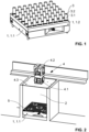
- the additive manufacturing device shown has a construction shaft, the interior of which is the construction space 2.
- the construction platform system 1 in the form of the machine interface unit 1.1 with the calibration plate 5 attached thereto is inserted.
- the optics module 4 is installed on the construction shaft, with the support plate 4.3 sitting overlapping the construction shaft walls so that no ambient light penetrates the build space 2 during the recording of the image (in this case a photograph) of the calibration plate 5.
- the optical detection unit 4.1 used for image recording in this case a camera, is attached to the support plate 4.3 by means of the optics holder 4.2 such that the optical axis or viewing direction of the optical detection unit 4.1 is aligned perpendicular to the support plate 4.3; when the optics module 4 is installed as intended, the optical axis of the optical detection unit 4.1 is thus directed perpendicularly into the build space 2 of the additive manufacturing device and perpendicular to the calibration plate 5.
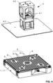
- FIG. 3 A first embodiment of the calibration system for calibrating the construction platform system 1 in the form of the machine interface unit 1.1 is shown in detail.
- the support plate 4.3 has light-emitting diodes on its (not visible) underside for illuminating the calibration plate 5.
- the optical detection unit 4.1 of the optics module 4 is fastened above the (not marked) light passage recess of the support plate 4.3 by means of the optics holder 4.2.
- the calibration plate 5 fixed on the machine interface unit 1.1 - in Fig. 3 before the introduction of the calibration pattern 6 - has five reference mark recesses 5.1, which allow the optical detection unit 4.1 to view the reference markings 8 arranged centrally on the end faces of the reference mark carriers 7.
- the reference mark carriers 7 are designed as calibration dowel pins 7.1 fitted into the machine interface unit 1.1 or as a hemispherical element 7.2 that can be magnetically fixed in the machine interface unit 1.1.
- the calibration plate 5 is fastened to the machine interface unit 1.1 by means of the fastening screws 9, whereby the spacers 10 are inserted between the calibration plate 5 and the machine interface unit 1.1, which ensure that the reference markings 8 are in a plane with the visible surface of the calibration plate 5.
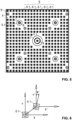
- the calibration system according to Fig. 4 corresponds to the Fig. 3 , but additionally shows the calibration pattern 6 introduced onto the visible side of the calibration plate 5 by means of the laser of the additive manufacturing device, consisting of the individual pattern elements 6.1 arranged periodically in rows and columns.
- Fig. 5 is the visible side of the Fig. 4
- the image created during the calibration process corresponds to the illustration in Fig. 5 .
- the actual position parameters for each of the two-dimensional pattern elements 6.1 are recorded and processed by the evaluation unit.
- the target-actual comparison of the target position parameters and the actual position parameters is illustrated using one of the sample elements 6.1 in the coordinate system Fig. 6
- the target position parameters of the two-dimensional pattern element 6.1 are the two specified target position coordinates X, Y and the target angular position in the two-dimensional plane, whereby the sample element 6.1, according to the specification, exhibits no rotation, i.e., always has a target angular position of 0°.
- the photographically determined actual position parameters are the two measured actual position coordinates X', Y' and the measured angular position deviation R' of the sample element 6.1.
- a second embodiment of the calibration system for calibrating the construction platform system 1 is shown.
- the optics module 4 located above it includes the optical detection unit 4.1, again a camera (the lens of which is in Fig. 7 visible), the optics mount 4.2, and a plate-shaped cover.
- This cover is a sandwich structure consisting of the bottom support plate 4.3, LED panels, and diffuser plates.
- Fig. 8 shows in a Fig. 7 corresponding illustration a housing 4.4 of the optics module 4, by means of which the optical detection unit 4.1, the optics holder 4.2 and the plate-shaped cover are housed or shielded.
- the calibration pattern 6 introduced on the visible side of the calibration plate 5 by means of the laser of the additive manufacturing device from the individual pattern elements 6.1 arranged periodically in rows and columns according to Fig. 9 differs with regard to the design of the sample elements 6.1 compared to the first embodiment of the calibration system according to Fig. 4 .
- the calibration plate 5 which is fixed to the calibration platform 1.3 by means of the fastening screws 9, has five reference mark recesses 5.1, which define the view of the optical detection unit 4.1 onto the reference markings 8 arranged centrally on the front sides of the reference mark carriers 7.
- the reference mark carriers 7 are designed as calibration pins 7.3, which - see Fig. 10 - are permanently installed on the calibration platform 1.3.
- the calibration plate 5 has a thickness corresponding to the height of the calibration pins 7.3, so that the reference markings 8 are in line with the visible surface of the calibration plate 5.
- the calibration platform 1.3 is - as further shown in Fig. 10 can be fixed in position on the machine interface unit 1.1 by means of a zero-point clamping system, guided by dowel pins.
Landscapes
- Engineering & Computer Science (AREA)
- Chemical & Material Sciences (AREA)
- Manufacturing & Machinery (AREA)
- Materials Engineering (AREA)
- Automation & Control Theory (AREA)
- Mechanical Engineering (AREA)
- Analytical Chemistry (AREA)
- Composite Materials (AREA)
- Physics & Mathematics (AREA)
- Plasma & Fusion (AREA)
- Length Measuring Devices By Optical Means (AREA)
- Conveying And Assembling Of Building Elements In Situ (AREA)
- Automatic Assembly (AREA)
- Machine Tool Units (AREA)
- Powder Metallurgy (AREA)
- Jigs For Machine Tools (AREA)
- Laser Beam Processing (AREA)
Applications Claiming Priority (3)
| Application Number | Priority Date | Filing Date | Title |
|---|---|---|---|
| DE102022129042.5A DE102022129042B3 (de) | 2022-11-03 | 2022-11-03 | Kalibriersystem und Kalibrierverfahren zur Kalibrierung eines Bauplattformsystems in einer additiven Fertigungsvorrichtung |
| DE102022129035.2A DE102022129035A1 (de) | 2022-11-03 | 2022-11-03 | Bauplattformsystem für die additive Fertigung |
| PCT/DE2023/150028 WO2024094256A1 (de) | 2022-11-03 | 2023-11-01 | Kalibriersystem und kalibrierverfahren zur kalibrierung eines bauplattformsystems in einer additiven fertigungsvorrichtung |
Publications (3)
| Publication Number | Publication Date |
|---|---|
| EP4479210A1 EP4479210A1 (de) | 2024-12-25 |
| EP4479210C0 EP4479210C0 (de) | 2025-06-18 |
| EP4479210B1 true EP4479210B1 (de) | 2025-06-18 |
Family
ID=88778543
Family Applications (2)
| Application Number | Title | Priority Date | Filing Date |
|---|---|---|---|
| EP23805459.7A Active EP4479210B1 (de) | 2022-11-03 | 2023-11-01 | Kalibriersystem und kalibrierverfahren zur kalibrierung eines bauplattformsystems in einer additiven fertigungsvorrichtung |
| EP23804913.4A Pending EP4611957A1 (de) | 2022-11-03 | 2023-11-01 | Bauplattformsystem für die additive fertigung |
Family Applications After (1)
| Application Number | Title | Priority Date | Filing Date |
|---|---|---|---|
| EP23804913.4A Pending EP4611957A1 (de) | 2022-11-03 | 2023-11-01 | Bauplattformsystem für die additive fertigung |
Country Status (7)
| Country | Link |
|---|---|
| EP (2) | EP4479210B1 (pl) |
| JP (2) | JP2025540915A (pl) |
| KR (2) | KR20250107187A (pl) |
| AU (2) | AU2023374904A1 (pl) |
| ES (1) | ES3039883T3 (pl) |
| PL (1) | PL4479210T3 (pl) |
| WO (2) | WO2024094256A1 (pl) |
Families Citing this family (1)
| Publication number | Priority date | Publication date | Assignee | Title |
|---|---|---|---|---|
| CN118914224B (zh) * | 2024-07-29 | 2025-11-18 | 歌尔股份有限公司 | 校准装置及校准方法 |
Family Cites Families (20)
| Publication number | Priority date | Publication date | Assignee | Title |
|---|---|---|---|---|
| DE4307342C2 (de) | 1993-03-09 | 1994-12-08 | Erowa Ag | Einrichtung zum positionsdefinierten Aufspannen eines Werkstücks am Arbeitsplatz einer Bearbeitungsmaschine |
| DE4437284A1 (de) | 1994-10-18 | 1996-04-25 | Eos Electro Optical Syst | Verfahren zum Kalibrieren einer Steuerung zur Ablenkung eines Laserstrahls |
| DE19918631A1 (de) | 1999-04-23 | 2000-10-26 | Eberspaecher J Gmbh & Co | Lagerelement für eine stirnseitige Befestigung der Längsenden eines tonnenförmig gebogenen Lichtbandes einer Dachkonstruktion |
| DE19918613A1 (de) | 1999-04-23 | 2000-11-30 | Eos Electro Optical Syst | Verfahren zur Kalibrierung einer Vorrichtung zum Herstellen eines dreidimensionalen Objektes, Kalibrierungsvorrichtung und Verfahren und Vorrichtung zur Herstellung eines dreidimensionalen Objektes |
| CZ309713B6 (cs) | 2013-08-20 | 2023-08-16 | Erowa Ag | Upínací zařízení |
| WO2017158327A1 (en) | 2016-03-14 | 2017-09-21 | Renishaw Plc | Calibration of additive manufacturing apparatus |
| FR3067624B1 (fr) * | 2017-06-19 | 2021-12-17 | Addup | Calibration d'un systeme de tete d'une source de rayonnement de puissance d'un appareil de fabrication additive |
| DE102017115989B4 (de) | 2017-07-17 | 2024-10-17 | Fraunhofer-Gesellschaft zur Förderung der angewandten Forschung e.V. | Verfahren zur additiven Fertigung sowie Substrateinheit-System |
| NL2019603B1 (en) * | 2017-09-21 | 2019-03-28 | Additive Ind Bv | Method for calibrating an apparatus for producing an object by means of additive manufacturing |
| DE102017219333A1 (de) | 2017-10-27 | 2019-05-02 | Siemens Aktiengesellschaft | Verfahren zur Modifikation von Bauteilen unter Einsatz additiver Fertigung |
| US10814439B2 (en) | 2018-05-31 | 2020-10-27 | General Electric Company | Turbomachine repair using additive manufacturing |
| CN113382842A (zh) | 2019-01-30 | 2021-09-10 | 通用电气公司 | 用于修复部件的增材制造系统和方法 |
| EP3725499A1 (de) | 2019-04-15 | 2020-10-21 | Siemens Aktiengesellschaft | Kalibrierung einer zur überwachung eines additiven fertigungsverfahrens vorgesehenen kamera |
| DE102019130676B4 (de) | 2019-11-13 | 2021-11-25 | Fraunhofer-Gesellschaft zur Förderung der angewandten Forschung e.V. | Halterungsvorrichtung mit einem Fixiermechanismus zur lösbaren Fixierung von stiftförmigen Elementen, Halterungsvorrichtungssystem sowie Verwendung der Halterungsvorrichtung |
| JP7041293B1 (ja) * | 2021-02-15 | 2022-03-23 | 株式会社ソディック | 三次元造形物の製造方法およびシート裁断装置の製造方法 |
| DE102021105918A1 (de) | 2021-03-11 | 2022-09-15 | Lufthansa Technik Aktiengesellschaft | Additives Reparatursystem |
| CN113732315B (zh) * | 2021-08-05 | 2023-12-22 | 华南理工大学 | 一种用于slm修复涡轮叶片的固定调平方法 |
| ES2987834T3 (es) | 2021-09-16 | 2024-11-18 | United Grinding Group Man Ag | Sistema de fabricación para la fabricación aditiva de una pieza de trabajo |
| DE102022129035A1 (de) | 2022-11-03 | 2024-05-08 | additiveStream4D GmbH | Bauplattformsystem für die additive Fertigung |
| DE102022129042B3 (de) * | 2022-11-03 | 2023-09-21 | additiveStream4D GmbH | Kalibriersystem und Kalibrierverfahren zur Kalibrierung eines Bauplattformsystems in einer additiven Fertigungsvorrichtung |
-
2023
- 2023-11-01 EP EP23805459.7A patent/EP4479210B1/de active Active
- 2023-11-01 KR KR1020257016917A patent/KR20250107187A/ko active Pending
- 2023-11-01 WO PCT/DE2023/150028 patent/WO2024094256A1/de not_active Ceased
- 2023-11-01 ES ES23805459T patent/ES3039883T3/es active Active
- 2023-11-01 PL PL23805459.7T patent/PL4479210T3/pl unknown
- 2023-11-01 WO PCT/DE2023/150027 patent/WO2024094255A1/de not_active Ceased
- 2023-11-01 AU AU2023374904A patent/AU2023374904A1/en active Pending
- 2023-11-01 KR KR1020257016922A patent/KR20250107188A/ko active Pending
- 2023-11-01 JP JP2025526266A patent/JP2025540915A/ja active Pending
- 2023-11-01 JP JP2025526357A patent/JP2025538162A/ja active Pending
- 2023-11-01 AU AU2023374905A patent/AU2023374905A1/en active Pending
- 2023-11-01 EP EP23804913.4A patent/EP4611957A1/de active Pending
Also Published As
| Publication number | Publication date |
|---|---|
| PL4479210T3 (pl) | 2025-09-29 |
| JP2025540915A (ja) | 2025-12-17 |
| JP2025538162A (ja) | 2025-11-26 |
| WO2024094256A1 (de) | 2024-05-10 |
| EP4479210A1 (de) | 2024-12-25 |
| AU2023374904A1 (en) | 2025-06-05 |
| EP4479210C0 (de) | 2025-06-18 |
| ES3039883T3 (en) | 2025-10-27 |
| KR20250107187A (ko) | 2025-07-11 |
| EP4611957A1 (de) | 2025-09-10 |
| KR20250107188A (ko) | 2025-07-11 |
| WO2024094255A1 (de) | 2024-05-10 |
| AU2023374905A1 (en) | 2025-06-05 |
Similar Documents
| Publication | Publication Date | Title |
|---|---|---|
| DE102004054876B3 (de) | Vermessungseinrichtung zur 3D-Vermessung von Zahnmodellen, Verschiebeplatte und Verfahren dazu | |
| EP1048441B1 (de) | Verfahren zur Kalibrierung einer Vorrichtung zum Herstellen eines dreidimensionalen Objektes und Kalibrierungsvorrichtung | |
| EP3300885B1 (de) | Verfahren zum kalibrieren einer vorrichtung zum herstellen eines dreidimensionalen objekts und zum durchführen des verfahrens ausgebildete vorrichtung | |
| EP2602433B1 (de) | Verfahren zum Herstellen eines zu beschichtenden Gasturbinen-Bauteils mit freigelegten Öffnungen | |
| EP3084347B1 (de) | Verfahren zur durchführung und kontrolle eines bearbeitungsschritts an einem werkstück | |
| DE102022129042B3 (de) | Kalibriersystem und Kalibrierverfahren zur Kalibrierung eines Bauplattformsystems in einer additiven Fertigungsvorrichtung | |
| DE102015102111A1 (de) | Mehrkopf-Laseranlage mit Sensoreinheit | |
| EP2933600A1 (de) | Verfahren und messsystem zum ermitteln der ausrichtung einer ersten riemenscheibe eines riemenantriebs in bezug auf eine zweite riemenscheibe des riemenantriebs | |
| EP4479210B1 (de) | Kalibriersystem und kalibrierverfahren zur kalibrierung eines bauplattformsystems in einer additiven fertigungsvorrichtung | |
| EP4337911B1 (de) | Messvorrichtung, fertigungsvorrichtung mit einer solchen messvorrichtung und verfahren zum betreiben einer fertigungsvorrichtung zum generativen fertigen eines bauteils aus einem pulvermaterial | |
| DE102009024752B4 (de) | Verfahren zum Vermessen und/oder Kalibrieren einer numerisch gesteuerten Werkzeugmaschine | |
| US20250262671A1 (en) | Calibration system and calibration method for calibrating a building platform system in an additive manufacturing device | |
| DE102017212371A1 (de) | Bestimmung einer Marke in einem Datensatz mit mittels zumindest eines Laserscanners erfassten dreidimensionalen Oberflächen-Koordinaten einer Szene | |
| EP1468792A2 (de) | Verfahren zum Kalibrieren eines Roboters | |
| DE102008022338B4 (de) | Verfahren zum Erfassen eines Kantenverlaufs einer Kante einer Platte | |
| WO2021013725A1 (de) | Fertigungssystem und verfahren zum einrichten einer werkzeugmaschine | |
| DE102023202610B4 (de) | Messsystem und Verfahren | |
| DE102022134495B4 (de) | Verfahren und Anlage zur Herstellung einer Kennzeichnung an einem Bauteil | |
| DE102020201952A1 (de) | Kalibrierung | |
| DE102022114445A1 (de) | Kalibrierungsverfahren und zur Herstellung eines dreidimensionalen Werkstücks eingerichtetes Drucksystem | |
| DE10327479A1 (de) | Einrichtung zur Bestimmung der Position eines Werkstücks und Verfahren dafür unter Verwendung von mindestens einer elektronischen Kamera | |
| DE102020200599A1 (de) | Verfahren und Vorrichtung zur Steigerung der Fertigungsgenauigkeit beim pulverbettbasierten Strahlschmelzen mit einem verfahrbaren Bearbeitungskopf | |
| EP3654034A1 (de) | Verfahren zum kalibrieren sowie verfahren und vorrichtung zur vermessung | |
| EP1431705A1 (de) | Einrichtung und Verfahren zur Bestimmung der Position eines Werkstücks unter Verwendung einer Schwenkneigekopfkamera | |
| EP3695278A1 (de) | Verfahren und belichtungseinrichtung zur belichtung von zumindest einer gespeicherten darstellung auf einem lichtempfindlichen aufzeichnungsträger |
Legal Events
| Date | Code | Title | Description |
|---|---|---|---|
| STAA | Information on the status of an ep patent application or granted ep patent |
Free format text: STATUS: UNKNOWN |
|
| STAA | Information on the status of an ep patent application or granted ep patent |
Free format text: STATUS: THE INTERNATIONAL PUBLICATION HAS BEEN MADE |
|
| PUAI | Public reference made under article 153(3) epc to a published international application that has entered the european phase |
Free format text: ORIGINAL CODE: 0009012 |
|
| STAA | Information on the status of an ep patent application or granted ep patent |
Free format text: STATUS: REQUEST FOR EXAMINATION WAS MADE |
|
| 17P | Request for examination filed |
Effective date: 20240919 |
|
| AK | Designated contracting states |
Kind code of ref document: A1 Designated state(s): AL AT BE BG CH CY CZ DE DK EE ES FI FR GB GR HR HU IE IS IT LI LT LU LV MC ME MK MT NL NO PL PT RO RS SE SI SK SM TR |
|
| GRAP | Despatch of communication of intention to grant a patent |
Free format text: ORIGINAL CODE: EPIDOSNIGR1 |
|
| STAA | Information on the status of an ep patent application or granted ep patent |
Free format text: STATUS: GRANT OF PATENT IS INTENDED |
|
| INTG | Intention to grant announced |
Effective date: 20250305 |
|
| GRAS | Grant fee paid |
Free format text: ORIGINAL CODE: EPIDOSNIGR3 |
|
| GRAA | (expected) grant |
Free format text: ORIGINAL CODE: 0009210 |
|
| STAA | Information on the status of an ep patent application or granted ep patent |
Free format text: STATUS: THE PATENT HAS BEEN GRANTED |
|
| AK | Designated contracting states |
Kind code of ref document: B1 Designated state(s): AL AT BE BG CH CY CZ DE DK EE ES FI FR GB GR HR HU IE IS IT LI LT LU LV MC ME MK MT NL NO PL PT RO RS SE SI SK SM TR |
|
| DAV | Request for validation of the european patent (deleted) | ||
| DAX | Request for extension of the european patent (deleted) | ||
| REG | Reference to a national code |
Ref country code: GB Ref legal event code: FG4D Free format text: NOT ENGLISH |
|
| REG | Reference to a national code |
Ref country code: CH Ref legal event code: EP |
|
| REG | Reference to a national code |
Ref country code: DE Ref legal event code: R096 Ref document number: 502023001199 Country of ref document: DE |
|
| REG | Reference to a national code |
Ref country code: CH Ref legal event code: EP |
|
| REG | Reference to a national code |
Ref country code: IE Ref legal event code: FG4D Free format text: LANGUAGE OF EP DOCUMENT: GERMAN |
|
| U01 | Request for unitary effect filed |
Effective date: 20250626 |
|
| U07 | Unitary effect registered |
Designated state(s): AT BE BG DE DK EE FI FR IT LT LU LV MT NL PT RO SE SI Effective date: 20250702 |
|
| PG25 | Lapsed in a contracting state [announced via postgrant information from national office to epo] |
Ref country code: NO Free format text: LAPSE BECAUSE OF FAILURE TO SUBMIT A TRANSLATION OF THE DESCRIPTION OR TO PAY THE FEE WITHIN THE PRESCRIBED TIME-LIMIT Effective date: 20250918 Ref country code: GR Free format text: LAPSE BECAUSE OF FAILURE TO SUBMIT A TRANSLATION OF THE DESCRIPTION OR TO PAY THE FEE WITHIN THE PRESCRIBED TIME-LIMIT Effective date: 20250919 |
|
| PG25 | Lapsed in a contracting state [announced via postgrant information from national office to epo] |
Ref country code: HR Free format text: LAPSE BECAUSE OF FAILURE TO SUBMIT A TRANSLATION OF THE DESCRIPTION OR TO PAY THE FEE WITHIN THE PRESCRIBED TIME-LIMIT Effective date: 20250618 |
|
| PG25 | Lapsed in a contracting state [announced via postgrant information from national office to epo] |
Ref country code: RS Free format text: LAPSE BECAUSE OF FAILURE TO SUBMIT A TRANSLATION OF THE DESCRIPTION OR TO PAY THE FEE WITHIN THE PRESCRIBED TIME-LIMIT Effective date: 20250918 |
|
| REG | Reference to a national code |
Ref country code: ES Ref legal event code: FG2A Ref document number: 3039883 Country of ref document: ES Kind code of ref document: T3 Effective date: 20251027 |
|
| U20 | Renewal fee for the european patent with unitary effect paid |
Year of fee payment: 3 Effective date: 20251110 |
|
| PG25 | Lapsed in a contracting state [announced via postgrant information from national office to epo] |
Ref country code: IS Free format text: LAPSE BECAUSE OF FAILURE TO SUBMIT A TRANSLATION OF THE DESCRIPTION OR TO PAY THE FEE WITHIN THE PRESCRIBED TIME-LIMIT Effective date: 20251018 |
|
| PG25 | Lapsed in a contracting state [announced via postgrant information from national office to epo] |
Ref country code: SM Free format text: LAPSE BECAUSE OF FAILURE TO SUBMIT A TRANSLATION OF THE DESCRIPTION OR TO PAY THE FEE WITHIN THE PRESCRIBED TIME-LIMIT Effective date: 20250618 |
|
| PG25 | Lapsed in a contracting state [announced via postgrant information from national office to epo] |
Ref country code: CZ Free format text: LAPSE BECAUSE OF FAILURE TO SUBMIT A TRANSLATION OF THE DESCRIPTION OR TO PAY THE FEE WITHIN THE PRESCRIBED TIME-LIMIT Effective date: 20250618 |
|
| PGFP | Annual fee paid to national office [announced via postgrant information from national office to epo] |
Ref country code: PL Payment date: 20251024 Year of fee payment: 3 |
|
| PG25 | Lapsed in a contracting state [announced via postgrant information from national office to epo] |
Ref country code: SK Free format text: LAPSE BECAUSE OF FAILURE TO SUBMIT A TRANSLATION OF THE DESCRIPTION OR TO PAY THE FEE WITHIN THE PRESCRIBED TIME-LIMIT Effective date: 20250618 |
|
| PGFP | Annual fee paid to national office [announced via postgrant information from national office to epo] |
Ref country code: ES Payment date: 20251216 Year of fee payment: 3 |