EP4478634A1 - Signalübertragungsverfahren und -vorrichtung - Google Patents
Signalübertragungsverfahren und -vorrichtung Download PDFInfo
- Publication number
- EP4478634A1 EP4478634A1 EP22938116.5A EP22938116A EP4478634A1 EP 4478634 A1 EP4478634 A1 EP 4478634A1 EP 22938116 A EP22938116 A EP 22938116A EP 4478634 A1 EP4478634 A1 EP 4478634A1
- Authority
- EP
- European Patent Office
- Prior art keywords
- spreading code
- spreading
- signal
- code sequence
- groups
- Prior art date
- Legal status (The legal status is an assumption and is not a legal conclusion. Google has not performed a legal analysis and makes no representation as to the accuracy of the status listed.)
- Pending
Links
Images


Classifications
-
- H—ELECTRICITY
- H04—ELECTRIC COMMUNICATION TECHNIQUE
- H04J—MULTIPLEX COMMUNICATION
- H04J13/00—Code division multiplex systems
- H04J13/16—Code allocation
-
- H—ELECTRICITY
- H04—ELECTRIC COMMUNICATION TECHNIQUE
- H04B—TRANSMISSION
- H04B1/00—Details of transmission systems, not covered by a single one of groups H04B3/00 - H04B13/00; Details of transmission systems not characterised by the medium used for transmission
- H04B1/69—Spread spectrum techniques
- H04B1/692—Hybrid techniques using combinations of two or more spread spectrum techniques
-
- H—ELECTRICITY
- H04—ELECTRIC COMMUNICATION TECHNIQUE
- H04B—TRANSMISSION
- H04B1/00—Details of transmission systems, not covered by a single one of groups H04B3/00 - H04B13/00; Details of transmission systems not characterised by the medium used for transmission
- H04B1/69—Spread spectrum techniques
- H04B1/707—Spread spectrum techniques using direct sequence modulation
-
- H—ELECTRICITY
- H04—ELECTRIC COMMUNICATION TECHNIQUE
- H04B—TRANSMISSION
- H04B1/00—Details of transmission systems, not covered by a single one of groups H04B3/00 - H04B13/00; Details of transmission systems not characterised by the medium used for transmission
- H04B1/69—Spread spectrum techniques
- H04B1/7163—Spread spectrum techniques using impulse radio
-
- H—ELECTRICITY
- H04—ELECTRIC COMMUNICATION TECHNIQUE
- H04J—MULTIPLEX COMMUNICATION
- H04J13/00—Code division multiplex systems
- H04J13/10—Code generation
-
- H—ELECTRICITY
- H04—ELECTRIC COMMUNICATION TECHNIQUE
- H04J—MULTIPLEX COMMUNICATION
- H04J13/00—Code division multiplex systems
- H04J13/10—Code generation
- H04J13/102—Combining codes
- H04J13/107—Combining codes by concatenation
-
- H—ELECTRICITY
- H04—ELECTRIC COMMUNICATION TECHNIQUE
- H04L—TRANSMISSION OF DIGITAL INFORMATION, e.g. TELEGRAPHIC COMMUNICATION
- H04L25/00—Baseband systems
- H04L25/02—Details ; arrangements for supplying electrical power along data transmission lines
- H04L25/0202—Channel estimation
- H04L25/0212—Channel estimation of impulse response
-
- H—ELECTRICITY
- H04—ELECTRIC COMMUNICATION TECHNIQUE
- H04L—TRANSMISSION OF DIGITAL INFORMATION, e.g. TELEGRAPHIC COMMUNICATION
- H04L27/00—Modulated-carrier systems
- H04L27/26—Systems using multi-frequency codes
- H04L27/2601—Multicarrier modulation systems
- H04L27/2602—Signal structure
- H04L27/2605—Symbol extensions, e.g. Zero Tail, Unique Word [UW]
Definitions
- Embodiments of this application claim priority to Chinese Patent Application No. 202210427671.0, filed with the China National Intellectual Property Administration on April 22, 2022 and entitled "METHOD FOR GENERATING SPREAD SPECTRUM CODE", which is incorporated in the embodiments of this application by reference in its entirety.
- Embodiments of this application relate to the field of communication technologies, and in particular, to a signal transmission method and apparatus.
- UWB ultra-wideband
- CIR channel impulse response
- a transmitter usually needs to send a signal that carries a preamble symbol to a receiver.
- the receiver may obtain a CIR based on a correlation between the signal and a known transmission sequence, and then obtain a correlation peak by using the CIR to determine a ranging timestamp to implement ranging.
- a deterministic random binary sequence may be used as a spread spectrum code to spread a preamble symbol, so as to improve security of the preamble symbol.
- ISI intersymbol interference
- the use of the deterministic random binary sequence for spread spectrum results in a decrease in the correlation of the preamble symbol. Therefore, how to improve a correlation between spread preamble symbols is one of the problems that need to be urgently resolved by a person skilled in the art.
- Embodiments of this application provide a signal transmission method and apparatus, to improve a correlation between spread preamble symbols. To achieve the foregoing objectives, the following technical solutions are used in embodiments of this application.
- an embodiment of this application provides a signal transmission method.
- the method includes: first spreading a preamble symbol based on a first spreading code sequence to generate a first signal, and then sending the first signal to a receiver.
- the first signal is used to determine a channel impulse response.
- the first spreading code sequence includes a plurality of spreading code groups, each spreading code group includes a plurality of same spreading codes and at least one guard symbol, a first bit and/or a last bit of each spreading code group are/is a guard symbol, and the plurality of spreading code groups include at least two spreading code groups with different spreading codes.
- the preamble symbol is spread by using the first spreading code sequence. Because there is a guard symbol in each spreading code group in the first spreading code sequence, the guard symbol can suppress intersymbol interference between spreading code groups. In addition, because there are a plurality of same spreading codes in each spreading code group, the preamble symbol is spread by using a spreading code group including a plurality of same spreading codes, so that a correlation between preamble symbols can be reserved. Therefore, in comparison with a case in which a preamble symbol is spread by using a deterministic random binary sequence as a spreading code, the signal transmission method provided in this embodiment of this application can improve a correlation between spread preamble symbols.
- the preamble symbol is spread by using the first spreading code sequence.
- the plurality of spreading code groups include the at least two spreading code groups with different spreading codes, randomness of the spreading code sequence is improved. Therefore, compared with spreading the preamble symbol by using all-one code or a specified ternary/binary code as a spreading code, security of the spread preamble symbol can be improved in the signal transmission method provided in this embodiment of this application.
- first N bits of each spreading code group in the plurality of spreading code groups may be guard symbols.
- last N bits of each spreading code group in the plurality of spreading code groups may be guard symbols.
- first K bits and last J bits of each spreading code group in the plurality of spreading code groups may be guard symbols.
- K and J may be equal or may be different.
- the guard symbol may include a zero code.
- the plurality of spreading code groups may have a same quantity of symbols.
- adjacent spreading code groups in the plurality of spreading code groups have different spreading codes.
- a spreading code group 1 is adjacent to a spreading code group 2. If the spreading code group 1 includes a plurality of spreading codes A1 and guard symbols, the spreading code group 2 includes a plurality of same spreading codes (for example, A2) other than A1 and guard symbols.
- spreading codes of two adjacent spreading code groups in the first spreading code sequence are different, so that randomness of the first spreading code sequence can be improved, thereby improving security of the spread preamble symbol by using the first spreading code sequence.
- an embodiment of this application provides another signal transmission method.
- the method includes: receiving a first signal sent by a transmitter, and determining a channel impulse response based on a first spreading code sequence and the first signal.
- the first signal is a signal generated by spreading the first spreading code sequence
- the first spreading code sequence includes a plurality of spreading code groups
- each spreading code group includes a plurality of same spreading codes and at least one guard symbol
- a first bit and/or a last bit of each spreading code group are/is a guard symbol
- the plurality of spreading code groups include at least two spreading code groups with different spreading codes.
- the channel impulse response is determined based on the first spreading code sequence and the first signal. Because there is a guard symbol in each spreading code group in the first spreading code sequence, the guard symbol can suppress intersymbol interference between spreading code groups. Therefore, in comparison with a case in which a preamble symbol is spread by using a deterministic random binary sequence as a spreading code, the signal transmission method provided in this embodiment of this application can improve a correlation between spread preamble symbols.
- the channel impulse response is determined based on the first spreading code sequence and the first signal. Because the plurality of spreading code groups include the at least two spreading code groups with different spreading codes, randomness of the spreading code sequence is improved. Therefore, compared with spreading the preamble symbol by using all-one code or a specified ternary/binary code as a spreading code, security of the spread preamble symbol can be improved in the signal transmission method provided in this embodiment of this application.
- first N bits of each spreading code group in the plurality of spreading code groups may be guard symbols.
- last N bits of each spreading code group in the plurality of spreading code groups may be guard symbols.
- first K bits and last J bits of each spreading code group in the plurality of spreading code groups may be guard symbols.
- K and J may be equal or may be different.
- the guard symbol may include a zero code.
- the plurality of spreading code groups may have a same quantity of symbols.
- adjacent spreading code groups in the plurality of spreading code groups have different spreading codes.
- a spreading code group 1 is adjacent to a spreading code group 2. If the spreading code group 1 includes a plurality of spreading codes A1 and guard symbols, the spreading code group 2 includes a plurality of same spreading codes (for example, A2) other than A1 and guard symbols.
- spreading codes of two adjacent spreading code groups in the first spreading code sequence are different, so that randomness of the first spreading code sequence can be improved, thereby improving security of the spread preamble symbol by using the first spreading code sequence.
- an embodiment of this application provides another signal transmission method.
- the method includes: receiving a second signal sent by a transmitter; replacing a first bit and/or a last bit of each spreading code group in the second spreading code sequence with a guard symbol to obtain a third spreading code sequence; and determining a channel impulse response based on the third spreading code sequence and the second signal.
- the channel impulse response is determined based on the third spreading code sequence and the second signal. Because there is a guard symbol in each spreading code group in the third spreading code sequence, the guard symbol can suppress intersymbol interference between spreading code groups. Therefore, in comparison with a case in which a preamble symbol is spread by using a deterministic random binary sequence as a spreading code, the signal transmission method provided in this embodiment of this application can improve a correlation between spread preamble symbols.
- the channel impulse response is determined based on the third spreading code sequence and the second signal.
- the plurality of spreading code groups include the at least two spreading code groups with different spreading codes, randomness of the spreading code sequence is improved. Therefore, compared with spreading the preamble symbol by using all-one code or a specified ternary/binary code as a spreading code, security of the spread preamble symbol can be improved in the signal transmission method provided in this embodiment of this application.
- first N bits of each spreading code group in the second spreading code sequence may be replaced with guard symbols to obtain the third spreading code sequence.
- last N bits of each spreading code group in the second spreading code sequence may be replaced with guard symbols to obtain the third spreading code sequence.
- first K bits and last J bits of each spreading code group in the second spreading code sequence may be replaced with guard symbols to obtain the third spreading code sequence.
- K and J may be equal or may be different.
- the guard symbol may include a zero code.
- the plurality of spreading code groups may have a same quantity of symbols.
- adjacent spreading code groups in the plurality of spreading code groups have different spreading codes.
- an embodiment of this application provides a signal transmission apparatus.
- the signal transmission apparatus includes a generation unit and a sending unit.
- the generation unit is configured to spread a preamble symbol based on a first spreading code sequence to generate a first signal, where the first signal is used to determine a channel impulse response; and the sending unit is configured to send the first signal to a receiver.
- the first spreading code sequence includes a plurality of spreading code groups, each spreading code group includes a plurality of same spreading codes and at least one guard symbol, a first bit and/or a last bit of each spreading code group are/is a guard symbol, and the plurality of spreading code groups include at least two spreading code groups with different spreading codes.
- the guard symbol may include a zero code.
- the plurality of spreading code groups may have a same quantity of symbols.
- adjacent spreading code groups in the plurality of spreading code groups have different spreading codes.
- an embodiment of this application provides another signal transmission apparatus.
- the signal transmission apparatus includes a receiving unit and a determining unit.
- the receiving unit is configured to receive a first signal sent by a transmitter, where the first signal is a signal generated by spreading a first spreading code sequence; and the determining unit is configured to determine a channel impulse response based on the first spreading code sequence and the first signal.
- the first spreading code sequence includes a plurality of spreading code groups, each spreading code group includes a plurality of same spreading codes and at least one guard symbol, a first bit and/or a last bit of each spreading code group are/is a guard symbol, and the plurality of spreading code groups include at least two spreading code groups with different spreading codes.
- the guard symbol may include a zero code.
- the plurality of spreading code groups may have a same quantity of symbols.
- adjacent spreading code groups in the plurality of spreading code groups have different spreading codes.
- an embodiment of this application provides another signal transmission apparatus.
- the signal transmission apparatus includes a receiving unit, a processing unit, and a determining unit.
- the receiving unit is configured to receive a second signal sent by a transmitter, and the second signal is a signal generated by spreading a second spreading code sequence;
- the processing unit is configured to replace a first bit and/or a last bit of each spreading code group in the second spreading code sequence with a guard symbol to obtain a third spreading code sequence;
- the determining unit is configured to determine a channel impulse response according to the third spreading code sequence and the second signal.
- the second spreading code sequence includes a plurality of spreading code groups, and each spreading code group includes a plurality of same spreading codes.
- the guard symbol may include a zero code.
- the plurality of spreading code groups may have a same quantity of symbols.
- adjacent spreading code groups in the plurality of spreading code groups have different spreading codes.
- an embodiment of this application further provides a signal transmission apparatus.
- the signal transmission apparatus includes at least one processor, and when the at least one processor executes program code or instructions, the method according to any one of the first aspect or the possible implementations of the first aspect is implemented.
- the signal processing apparatus may further include at least one memory, and the at least one memory is configured to store the program code or the instructions.
- an embodiment of this application further provides a chip, including an input interface, an output interface, and at least one processor.
- the chip further includes a memory.
- the at least one processor is configured to execute code in the memory.
- the chip implements the method according to any one of the first aspect or the possible implementations of the first aspect.
- the chip may be an integrated circuit.
- an embodiment of this application further provides a computer-readable storage medium, configured to store a computer program.
- the computer program is configured to implement the method according to any one of the first aspect or the possible implementations of the first aspect.
- an embodiment of this application further provides a computer program product including instructions.
- the computer program product runs on a computer, the computer is enabled to implement the method according to any one of the first aspect or the possible implementations of the first aspect.
- the signal transmission apparatus, the computer storage medium, the computer program product, and the chip provided in this embodiment are all configured to perform the method provided above. Therefore, for beneficial effects that can be achieved by the signal transmission apparatus, the computer storage medium, the computer program product, and the chip, refer to the beneficial effects in the method provided above. Details are not described herein again.
- a and/or B may represent the following three cases: Only A exists, both A and B exist, and only B exists.
- a process, a method, a system, a product, or a device that includes a series of steps or units is not limited to the listed steps or units, but optionally further includes other unlisted steps or units, or optionally further includes another inherent step or unit of the process, the method, the product, or the device.
- example or “for example” is used to represent giving an example, an illustration, or a description. Any embodiment or design scheme described as an “example” or “for example” in embodiments of this application should not be explained as being more preferred or having more advantages than another embodiment or design scheme. Exactly, use of the term “example”, “for example”, or the like is intended to present a relative concept in a specific manner.
- a plurality of means two or more than two.
- the UWB technology has emerged to be a popular commercial choice for low-power and high-precision positioning.
- a range of a target can be determined by a CIR, so the acquisition of the CIR is a critical part of UWB communication and ranging.
- a transmitter usually needs to send a signal that carries a preamble symbol (preamble) to a receiver.
- the receiver may obtain a CIR by using a correlation between the signal and a known transmission sequence, and then obtain a correlation peak by using the CIR to determine a ranging timestamp to implement ranging.
- a deterministic random binary sequence may be used as a spread spectrum code to spread a preamble symbol, so as to improve security of the preamble symbol.
- the use of the deterministic random binary sequence for spread spectrum results in a decrease in the correlation of the preamble symbol.
- an embodiment of this application provides a signal transmission method, to improve a correlation between spread preamble symbols.
- the method may be used in a signal transmission system, the signal transmission system includes a transmitter and a receiver, and both the transmitter and the receiver include an ultra-wideband system.
- a device configured to send a signal is referred to as a transmitter, and a device configured to receive a signal is referred to as a receiver.
- the transmitter may also receive a signal, and the receiver may also send a signal.
- a function of the device is not limited in embodiments of this application.
- FIG. 1 is a schematic flowchart of a signal transmission method according to an embodiment of this application.
- the method is applied to a transmitter in a signal transmission system.
- the transmitter includes an ultra-wideband system.
- the method may include the following procedure.
- S101 Spread a preamble symbol based on a first spreading code sequence to generate a first signal.
- the first signal is used to determine a channel impulse response.
- the first signal may also be referred to as a channel impulse response training sequence (CIR training sequence, CTS).
- CIR training sequence CTS
- the preamble symbol may be generated by spreading a preamble or not spreading a preamble. For example, if the preamble has 31 bits, and the preamble is spread by 16 times, a preamble symbol with a length of 496 may be obtained.
- the first spreading code sequence includes a plurality of spreading code groups, each spreading code group includes a plurality of same spreading codes and at least one guard symbol, a first bit and/or a last bit of each spreading code group are/is a guard symbol, and the plurality of spreading code groups include at least two spreading code groups with different spreading codes.
- first N bits of each spreading code group in the plurality of spreading code groups may be guard symbols.
- last N bits of each spreading code group in the plurality of spreading code groups may be guard symbols.
- first K bits and last J bits of each spreading code group in the plurality of spreading code groups may be guard symbols.
- K and J may be equal or may be different.
- the guard symbol may include a zero code.
- the plurality of spreading code groups may have a same quantity of symbols.
- adjacent spreading code groups in the plurality of spreading code groups have different spreading codes.
- a spreading code group 1 is adjacent to a spreading code group 2. If the spreading code group 1 includes a plurality of spreading codes A1 and guard symbols, the spreading code group 2 includes a plurality of same spreading codes (for example, A2) other than A1 and guard symbols.
- spreading codes of two adjacent spreading code groups in the first spreading code sequence are different, so that randomness of the first spreading code sequence can be improved, thereby improving security of the spread preamble symbol by using the first spreading code sequence.
- spreading codes of the plurality of spreading code groups may be different.
- Group represents a quantity of spreading code groups in the spreading code sequence
- Ntr is a quantity of spreading codes in the spreading code group
- Ntz is a quantity of guard symbols in the spreading code group
- the first spreading code sequence includes four spreading code groups, and each spreading code group includes three spreading codes and one guard symbol.
- the transmitter may determine spreading codes of each spreading code group from a plurality of independent codes.
- the transmitter may determine the spreading code of the spreading code group from eight independent codes, namely, A_0, A_1, A_2, A_3, A_4, A_5, A_6, and A_7.
- A0 is determined as a spreading code of a spreading code group 1
- A1 is determined as a spreading code of a spreading code group 2.
- Values of A_0, A_1, A_2, A_3, A_4, A_5, A_6, and A_7 may be 0, 1, 2, 3, 4, 5, 6, 7, or another value. This is not limited in this embodiment of this application.
- S102 Send the first signal to a receiver.
- a specific method for sending the first signal to the receiver may be processed by using any method that can be thought of by a person skilled in the art. This is not specifically limited in this embodiment of this application.
- the transmitter may send the first signal to the receiver by using a UWB communication technology.
- the transmitter may also send the first signal to the receiver by using an impulse radio (impulse radio UWB, IR-UWB) communication technology.
- impulse radio impulse radio UWB, IR-UWB
- the channel impulse response is determined based on a third spreading code sequence and a second signal. Because there is a guard symbol in each spreading code group in the third spreading code sequence, the guard symbol can suppress intersymbol interference between spreading code groups. Therefore, in comparison with a case in which a preamble symbol is spread by using a deterministic random binary sequence as a spreading code, the signal transmission method provided in this embodiment of this application can improve a correlation between spread preamble symbols.
- the channel impulse response is determined based on the third spreading code sequence and the second signal.
- the plurality of spreading code groups include the at least two spreading code groups with different spreading codes, randomness of the spreading code sequence is improved. Therefore, compared with spreading the preamble symbol by using all-one code or a specified ternary/binary code as a spreading code, security of the spread preamble symbol can be improved in the signal transmission method provided in this embodiment of this application.
- FIG. 2 is a schematic flowchart of another signal transmission method according to an embodiment of this application.
- the method is applied to a receiver in a signal transmission system.
- the receiver includes an ultra-wideband system.
- the method may include the following procedure.
- S201 Receive a first signal sent by a transmitter.
- a specific method for receiving the first signal sent by the transmitter may be processed by using any method that can be thought of by a person skilled in the art. This is not specifically limited in this embodiment of this application.
- the receiver may receive the first signal by using a UWB communication technology.
- the receiver may also receive the first signal by using an IR-UWB communication technology.
- first N bits of each spreading code group in a plurality of spreading code groups may be guard symbols.
- last N bits of each spreading code group in the plurality of spreading code groups may be guard symbols.
- first K bits and last J bits of each spreading code group in the plurality of spreading code groups may be guard symbols.
- K and J may be equal or may be different.
- the guard symbol may include a zero code.
- the plurality of spreading code groups may have a same quantity of symbols.
- adjacent spreading code groups in the plurality of spreading code groups have different spreading codes.
- a spreading code group 1 is adjacent to a spreading code group 2. If the spreading code group 1 includes a plurality of spreading codes A1 and guard symbols, the spreading code group 2 includes a plurality of same spreading codes (for example, A2) other than A1 and guard symbols.
- spreading codes of two adjacent spreading code groups in the first spreading code sequence are different, so that randomness of the first spreading code sequence can be improved, thereby improving security of the spread preamble symbol by using the first spreading code sequence.
- S202 Determine a channel impulse response based on a first spreading code sequence and the first signal.
- the receiver may first despread the first signal by using the first spreading code sequence to obtain a preamble symbol, and then determine the channel impulse response CIR based on the obtained preamble symbol.
- the channel impulse response is determined based on the first spreading code sequence and the first signal. Because there is a guard symbol in each spreading code group in the first spreading code sequence, the guard symbol can suppress intersymbol interference between spreading code groups. Therefore, in comparison with a case in which a preamble symbol is spread by using a deterministic random binary sequence as a spreading code, the signal transmission method provided in this embodiment of this application can improve a correlation between spread preamble symbols.
- the channel impulse response is determined based on the first spreading code sequence and the first signal. Because the plurality of spreading code groups include the at least two spreading code groups with different spreading codes, randomness of the spreading code sequence is improved. Therefore, compared with spreading the preamble symbol by using all-one code or a specified ternary/binary code as a spreading code, security of the spread preamble symbol can be improved in the signal transmission method provided in this embodiment of this application.
- FIG. 3 is a schematic flowchart of still another signal transmission method according to an embodiment of this application.
- the method is applied to a signal transmission system.
- the signal transmission system includes a transmitter and a receiver. Both the transmitter and the receiver include an ultra-wideband system.
- the method may include the following procedure.
- S301 The transmitter spreads a preamble symbol based on a first spreading code sequence to generate a first signal.
- the first signal is used to determine a channel impulse response.
- the first signal may also be referred to as aCTS.
- the first spreading code sequence includes a plurality of spreading code groups, each spreading code group includes a plurality of same spreading codes and at least one guard symbol, a first bit and/or a last bit of each spreading code group are/is a guard symbol, and the plurality of spreading code groups include at least two spreading code groups with different spreading codes.
- first N bits of each spreading code group in the plurality of spreading code groups may be guard symbols.
- last N bits of each spreading code group in the plurality of spreading code groups may be guard symbols.
- first K bits and last J bits of each spreading code group in the plurality of spreading code groups may be guard symbols.
- K and J may be equal or may be different.
- the guard symbol may include a zero code.
- the plurality of spreading code groups may have a same quantity of symbols.
- adjacent spreading code groups in the plurality of spreading code groups have different spreading codes.
- a spreading code group 1 is adjacent to a spreading code group 2. If the spreading code group 1 includes a plurality of spreading codes A1 and guard symbols, the spreading code group 2 includes a plurality of same spreading codes (for example, A2) other than A1 and guard symbols.
- spreading codes of two adjacent spreading code groups in the first spreading code sequence are different, so that randomness of the first spreading code sequence can be improved, thereby improving security of the spread preamble symbol by using the first spreading code sequence.
- spreading codes of the plurality of spreading code groups may be different.
- Group represents a quantity of spreading code groups in the spreading code sequence
- Ntr is a quantity of spreading codes in the spreading code group
- Ntz is a quantity of guard symbols in the spreading code group
- the first spreading code sequence includes four spreading code groups, and each spreading code group includes three spreading codes and one guard symbol.
- the transmitter may determine spreading codes of each spreading code group from a plurality of independent codes.
- the transmitter may determine the spreading code of the spreading code group from eight independent codes, namely, A_0, A_1, A_2, A_3, A_4, A_5, A_6, and A_7.
- A0 is determined as a spreading code of a spreading code group 1
- A1 is determined as a spreading code of a spreading code group 2.
- Values of A_0, A_1, A_2, A_3, A_4, A_5, A_6, and A_7 may be 0, 1, 2, 3, 4, 5, 6, 7, or another value. This is not limited in this embodiment of this application.
- S302 The transmitter sends the first signal to a receiver.
- a specific method for sending the first signal to the receiver may be processed by using any method that can be thought of by a person skilled in the art. This is not specifically limited in this embodiment of this application.
- the transmitter may send the first signal to the receiver by using a UWB communication technology.
- the transmitter may also send the first signal to the receiver by using an IR-UWB communication technology.
- S303 The receiver receives the first signal sent by the transmitter.
- a specific method for receiving the first signal sent by the transmitter may be processed by using any method that can be thought of by a person skilled in the art. This is not specifically limited in this embodiment of this application.
- the receiver may receive the first signal by using a UWB communication technology.
- the receiver may also receive the first signal by using an IR-UWB communication technology.
- first N bits of each spreading code group in the plurality of spreading code groups may be guard symbols.
- last N bits of each spreading code group in the plurality of spreading code groups may be guard symbols.
- first K bits and last J bits of each spreading code group in the plurality of spreading code groups may be guard symbols.
- K and J may be equal or may be different.
- the guard symbol may include a zero code.
- the plurality of spreading code groups may have a same quantity of symbols.
- adjacent spreading code groups in the plurality of spreading code groups have different spreading codes.
- a spreading code group 1 is adjacent to a spreading code group 2. If the spreading code group 1 includes a plurality of spreading codes A1 and guard symbols, the spreading code group 2 includes a plurality of same spreading codes (for example, A2) other than A1 and guard symbols.
- spreading codes of two adjacent spreading code groups in the first spreading code sequence are different, so that randomness of the first spreading code sequence can be improved, thereby improving security of the spread preamble symbol by using the first spreading code sequence.
- S304 The receiver determines a channel impulse response based on the first spreading code sequence and the first signal.
- the receiver may first despread the first signal by using the first spreading code sequence to obtain a preamble symbol, and then determine the channel impulse response based on the obtained preamble symbol.
- the channel impulse response is determined based on the first spreading code sequence and the first signal. Because there is a guard symbol in each spreading code group in the first spreading code sequence, the guard symbol can suppress intersymbol interference between spreading code groups. Therefore, in comparison with a case in which a preamble symbol is spread by using a deterministic random binary sequence as a spreading code, the signal transmission method provided in this embodiment of this application can improve a correlation between spread preamble symbols.
- the channel impulse response is determined based on the first spreading code sequence and the first signal. Because the plurality of spreading code groups include the at least two spreading code groups with different spreading codes, randomness of the spreading code sequence is improved. Therefore, compared with spreading the preamble symbol by using all-one code or a specified ternary/binary code as a spreading code, security of the spread preamble symbol can be improved in the signal transmission method provided in this embodiment of this application.
- FIG. 4 is a schematic flowchart of still another signal transmission method according to an embodiment of this application.
- the method is applied to a receiver in a signal transmission system, and the transmitter includes an ultra-wideband system.
- the method may include the following procedure.
- S401 Receive a second signal sent by the transmitter.
- the second signal is a signal generated by spreading a second spreading code sequence, the second spreading code sequence includes a plurality of spreading code groups, and each spreading code group includes a plurality of same spreading codes.
- a specific method for receiving the second signal sent by the transmitter may be processed by using any method that can be thought of by a person skilled in the art. This is not specifically limited in this embodiment of this application.
- the receiver may receive the second signal by using a UWB communication technology.
- the receiver may also receive the second signal by using an IR-UWB communication technology.
- S402 Replace a first bit and/or a last bit of each spreading code group in the second spreading code sequence with a guard symbol to obtain a third spreading code sequence.
- first N bits of each spreading code group in the second spreading code sequence may be replaced with guard symbols to obtain the third spreading code sequence.
- last N bits of each spreading code group in the second spreading code sequence may be replaced with guard symbols to obtain the third spreading code sequence.
- first K bits and last J bits of each spreading code group in the second spreading code sequence may be replaced with guard symbols to obtain the third spreading code sequence.
- K and J may be equal or may be different.
- the guard symbol may include a zero code.
- the plurality of spreading code groups may have a same quantity of symbols.
- adjacent spreading code groups in the plurality of spreading code groups have different spreading codes.
- Ntr is a quantity of spreading codes in the spreading code group
- Ntz is a quantity of guard symbols in the spreading code group.
- S403 Determine a channel impulse response based on the third spreading code sequence and the second signal.
- the receiver may first despread the second signal by using the third spreading code sequence to obtain a preamble symbol, and then determine the channel impulse response based on the obtained preamble symbol.
- the channel impulse response is determined based on a third spreading code sequence and a second signal. Because there is a guard symbol in each spreading code group in the third spreading code sequence, the guard symbol can suppress intersymbol interference between spreading code groups. Therefore, in comparison with a case in which a preamble symbol is spread by using a deterministic random binary sequence as a spreading code, the signal transmission method provided in this embodiment of this application can improve a correlation between spread preamble symbols.
- the channel impulse response is determined based on the third spreading code sequence and the second signal.
- the plurality of spreading code groups include the at least two spreading code groups with different spreading codes, randomness of the spreading code sequence is improved. Therefore, compared with spreading the preamble symbol by using all-one code or a specified ternary/binary code as a spreading code, security of the spread preamble symbol can be improved in the signal transmission method provided in this embodiment of this application.
- FIG. 5 is a schematic flowchart of still another signal transmission method according to an embodiment of this application.
- the method is used in a signal transmission system.
- the signal transmission system includes a transmitter and a receiver. Both the transmitter and the receiver include an ultra-wideband system.
- the method may include the following procedure.
- S501 The transmitter sends a second signal to the receiver.
- the second signal is a signal generated by spreading a second spreading code sequence, the second spreading code sequence includes a plurality of spreading code groups, and each spreading code group includes a plurality of same spreading codes.
- a specific method for sending the second signal by the transmitter may be processed by using any method that can be thought of by a person skilled in the art. This is not specifically limited in this embodiment of this application.
- the transmitter may send the second signal by using a UWB communication technology.
- the transmitter may send the second signal by using an IR-UWB communication technology.
- S502 The receiver receives the second signal sent by the transmitter.
- a specific method for receiving the second signal sent by the transmitter may be processed by using any method that can be thought of by a person skilled in the art. This is not specifically limited in this embodiment of this application.
- the receiver may receive the second signal by using a UWB communication technology.
- the receiver may also receive the second signal by using an IR-UWB communication technology.
- S503 The receiver replaces a first bit and/or a last bit of each spreading code group in the second spreading code sequence with a guard symbol to obtain a third spreading code sequence.
- first N bits of each spreading code group in the second spreading code sequence may be replaced with guard symbols to obtain the third spreading code sequence.
- last N bits of each spreading code group in the second spreading code sequence may be replaced with guard symbols to obtain the third spreading code sequence.
- first K bits and last J bits of each spreading code group in the second spreading code sequence may be replaced with guard symbols to obtain the third spreading code sequence.
- K and J may be equal or may be different.
- the guard symbol may include a zero code.
- the plurality of spreading code groups may have a same quantity of symbols.
- adjacent spreading code groups in the plurality of spreading code groups have different spreading codes.
- Ntr is a quantity of spreading codes in the spreading code group
- Ntz is a quantity of guard symbols in the spreading code group.
- S504 The receiver determines a channel impulse response based on a third spreading code sequence and the second signal.
- the receiver may first despread the second signal by using the third spreading code sequence to obtain a preamble symbol, and then determine the channel impulse response based on the obtained preamble symbol.
- Table 1 shows a plurality of examples of a spreading code (spreading code sequence) design provided in embodiments of this application and a spreading code design used in an existing institute of electrical and electronics engineers (institute of electrical and electronics engineers, IEEE) 802.15.4 standard.
- A_0, A_1, A_2, A_3, A_4, A_5, A_6, and A_7 represent independent codes (security codes). Values of A_0, A_1, A_2, A_3, A_4, A_5, A_6, and A_7 may be 0, 1, 2, 3, 4, 5, 6, 7, or another value. This is not limited in this embodiment of this application.
- the CTS code is a spreading code of a channel impulse response training sequence.
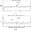
- FIG. 6 to FIG. 9 respectively show simulation use of 4 different spreading codes and the same preamble.
- the channel impulse response obtained by the signal is transmitted through an additive white gaussian noise (additive white gaussian noise, AWGN) channel.
- additive white gaussian noise AWGN
- FIG. 6 is a channel impulse response acquired by using an all-random spread code.
- FIG. 7 is a channel impulse response acquired by using an all-one spread code.
- FIG. 8 is a channel impulse response acquired by using a spreading code in a proposed special spread mode V1.
- FIG. 9 is a channel impulse response acquired by using a spreading code in a proposed special spread mode V2.
- a peak at an index 256 is a desired signal peak. It is worth mentioning that, ideally, the greater the power difference between a true signal peak and a noise peak, the better to avoid mis-detection during ranging.
- Ngroup that is, a quantity of spreading code groups in a spreading sequence
- Ngroup may be adjusted, so that a tradeoff and a balance between ranging performance and security can be achieved based on a requirement.
- the following describes, with reference to FIG. 10 to FIG. 12 , a signal transmission apparatus configured to perform the foregoing signal transmission method.
- the signal transmission apparatus includes a corresponding hardware and/or software module for performing each function.
- embodiments of this application may be implemented by hardware or a combination of hardware and computer software. Whether a function is performed by hardware or hardware driven by computer software depends on particular applications and design constraints of the technical solutions. A person skilled in the art may use different methods to implement the described functions for each particular application with reference to the embodiments, but it should not be considered that the implementation goes beyond the scope of the embodiments of this application.
- the signal transmission apparatus may be divided into functional modules based on the foregoing method examples.
- each functional module corresponding to each function may be obtained through division, or two or more functions may be integrated into one processing module.
- the integrated module may be implemented in a form of hardware. It should be noted that, in this embodiment, division into the modules is an example, is merely logical function division, and may be other division during actual implementation.
- FIG. 10 is a possible schematic composition diagram of the signal transmission apparatus in the foregoing embodiment.
- the signal transmission apparatus 1000 may include a generation unit 1001 and a sending unit 1002.
- the generation unit 1001 is configured to spread a preamble symbol based on a first spreading code sequence to generate a first signal, where the first signal is used to determine a channel impulse response.
- the sending unit 1002 is configured to send the first signal to a receiver.
- the first spreading code sequence includes a plurality of spreading code groups, each spreading code group includes a plurality of same spreading codes and at least one guard symbol, a first bit and/or a last bit of each spreading code group are/is a guard symbol, and the plurality of spreading code groups include at least two spreading code groups with different spreading codes.
- the guard symbol may include a zero code.
- the plurality of spreading code groups may have a same quantity of symbols.
- adjacent spreading code groups in the plurality of spreading code groups have different spreading codes.
- FIG. 11 is another possible schematic composition diagram of the signal transmission apparatus in the foregoing embodiment.
- the signal transmission apparatus 1100 may include a receiving unit 1101 and a determining unit 1102.
- the receiving unit 1101 is configured to receive a first signal sent by a transmitter, where the first signal is a signal generated by spreading a first spreading code sequence.
- the determining unit 1102 is configured to determine a channel impulse response based on the first spreading code sequence and the first signal.
- the first spreading code sequence includes a plurality of spreading code groups, each spreading code group includes a plurality of same spreading codes and at least one guard symbol, a first bit and/or a last bit of each spreading code group are/is a guard symbol, and the plurality of spreading code groups include at least two spreading code groups with different spreading codes.
- the guard symbol may include a zero code.
- the plurality of spreading code groups may have a same quantity of symbols.
- adjacent spreading code groups in the plurality of spreading code groups have different spreading codes.
- FIG. 12 is another possible schematic composition diagram of the signal transmission apparatus in the foregoing embodiment.
- the signal transmission apparatus 1200 may include a receiving unit 1201, a processing unit 1202, and a determining unit 1203.
- the receiving unit 1201 is configured to receive a second signal sent by a transmitter, and the second signal is a signal generated by spreading a second spreading code sequence.
- the processing unit 1202 is configured to replace a first bit and/or a last bit of each spreading code group in the second spreading code sequence with a guard symbol to obtain a third spreading code sequence.
- the determining unit 1203 is configured to determine a channel impulse response based on the third spreading code sequence and the second signal.
- the second spreading code sequence includes a plurality of spreading code groups, and each spreading code group includes a plurality of same spreading codes.
- the guard symbol may include a zero code.
- the plurality of spreading code groups may have a same quantity of symbols.
- adjacent spreading code groups in the plurality of spreading code groups have different spreading codes.
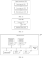
- FIG. 13 is a schematic diagram of a structure of a chip 1300.
- the chip 1300 includes one or more processors 1301 and an interface circuit 1302.
- the chip 1300 may further include a bus 1303.
- the processor 1301 may be an integrated circuit chip and has a signal processing capability. During implementation, steps of the foregoing encoding and decoding method may be implemented by using hardware integrated logical circuit in the processor 1301, or by using instructions in a form of software.
- the processor 1301 may be a general-purpose processor, a digital signal processor (digital signal processor, DSP), an application-specific integrated circuit (application-specific integrated circuit, ASIC), a field programmable gate array (field programmable gate array, FPGA) or another programmable logic device, a discrete gate or transistor logic device, or a discrete hardware component.
- the processor may implement or perform the methods and steps that are disclosed in embodiments of this application.
- the general-purpose processor may be a microprocessor, or the processor may be any conventional processor or the like.
- the interface circuit 1302 may be configured to send or receive data, instructions, or information.
- the processor 1301 may process the data, the instructions, or other information received by the interface circuit 1302, and may send processing completion information by using the interface circuit 1302.
- the chip further includes a memory.
- the memory may include a read-only memory and a random access memory, and provide operation instructions and data for the processor.
- a part of the memory may further include a non-volatile random access memory (non-volatile random access memory, NVRAM).
- the memory stores an executable software module or a data structure
- the processor may perform a corresponding operation by invoking operation instructions (the operation instructions may be stored in an operating system) stored in the memory.
- the chip may be used in the signal transmission apparatus in embodiments of this application.
- the interface circuit 1302 may be configured to output an execution result of the processor 1301.
- functions corresponding to each of the processor 1301 and the interface circuit 1302 may be implemented by using a hardware design, may be implemented by using a software design, or may be implemented by combining software and hardware. This is not limited herein.
- FIG. 14 is a schematic diagram of a structure of an electronic device according to an embodiment of this application.
- the electronic device 400 may be a signal transmission apparatus or a chip or a functional module in a signal transmission apparatus.
- the electronic device 1400 includes a processor 1401, a transceiver 1402, and a communication line 1403.
- the processor 1401 is configured to perform any step in the method embodiment shown in FIG. 1 , and when performing the step, may choose to invoke the transceiver 1402 and the communication line 1403 to complete a corresponding operation.
- the electronic device 1400 may further include a memory 1404.
- the processor 1401, the memory 1404, and the transceiver 1402 may be connected through the communication line 1403.
- the processor 1401 is a central processing unit (central processing unit, CPU), a general-purpose processor, a network processor (network processor, NP), a digital signal processor (digital signal processor, DSP), a microprocessor, a microcontroller, a programmable logic device (programmable logic device, PLD), or any combination thereof.
- the processor 1401 may alternatively be another apparatus having a processing function, for example, a circuit, a component, or a software module. This is not limited.
- the transceiver 1402 is configured to communicate with another device or another communication network.
- the another communication network may be Ethernet, a radio access network (radio access network, RAN), a wireless local area network (wireless local area network, WLAN), or the like.
- the transceiver 1402 may be a module, a circuit, a transceiver, or any apparatus that can implement communication.
- the transceiver 1402 is mainly configured to receive and send data, and may include a transmitter and a receiver, separately for sending and receiving a signal. Operations other than signal receiving and sending are implemented by the processor, such as information processing, calculation, and the like.
- the communication line 1403 is configured to transmit information between components included in the electronic device 1400.
- the processor may be considered as a logic circuit
- the transceiver may be considered as an interface circuit
- the memory 1404 is configured to store instructions.
- the instructions may be a computer program.
- the memory 1404 may be a volatile memory or a non-volatile memory, or may include both of a volatile memory and a non-volatile memory.
- the non-volatile memory may be a read-only memory (read-only memory, ROM), a programmable read-only memory (programmable ROM, PROM), an erasable programmable read-only memory (erasable PROM, EPROM), an electrically erasable programmable read-only memory (electrically EPROM, EEPROM), or a flash memory.
- the volatile memory may be a random access memory (random access memory, RAM), used as an external cache.
- RAMs may be used, for example, a static random access memory (static RAM, SRAM), a dynamic random access memory (dynamic RAM, DRAM), a synchronous dynamic random access memory (synchronous DRAM, SDRAM), a double data rate synchronous dynamic random access memory (double data rate SDRAM, DDR SDRAM), an enhanced synchronous dynamic random access memory (enhanced SDRAM, ESDRAM), a synchlink dynamic random access memory (synchlink DRAM, SLDRAM), and a direct rambus dynamic random access memory (direct rambus RAM, DR RAM).
- static random access memory static random access memory
- DRAM dynamic random access memory
- DRAM dynamic random access memory
- SDRAM synchronous dynamic random access memory
- double data rate SDRAM double data rate SDRAM
- DDR SDRAM double data rate SDRAM
- ESDRAM enhanced synchronous dynamic random access memory
- synchlink dynamic random access memory synchlink dynamic random access memory
- direct rambus RAM direct rambus RAM, DR RAM
- the memory 1404 may further be a compact disc read-only memory (compact disc read-only memory, CD-ROM) or another optical disc storage, an optical disc storage (including a compact disc, a laser disc, an optical disc, a digital versatile disc, a Blu-ray disc, or the like), a magnetic disk storage medium, another magnetic storage device, or the like. It should be noted that the memory of the systems and methods described in this specification includes but is not limited to these memories and any memory of another proper type.
- the memory 1404 may exist independently of the processor 1401, or may be integrated with the processor 1401.
- the memory 1404 may be configured to store instructions, program code, some data, or the like.
- the memory 1404 may be located inside the electronic device 1400, or may be located outside the electronic device 1400. This is not limited.
- the processor 1401 is configured to execute the instructions stored in the memory 1404, to implement the method provided in the foregoing embodiment of this application.
- the processor 1401 may include one or more processors, for example, a CPU 0 and a CPU 1 in FIG. 14 .
- the electronic device 1400 includes a plurality of processors.
- the electronic device 1400 may further include a processor 1407.
- the electronic device 1400 further includes an output device 1405 and an input device 1406.
- the input device 1406 is a device such as a keyboard, a mouse, a microphone, a joystick, or the like
- the output device 1405 is a device such as a display screen, a speaker (speaker), or the like.
- the electronic device 1400 may be a chip system or a device having a structure similar to that in FIG. 14 .
- the chip system may include a chip, or may include a chip and another discrete component.
- Mutual reference may be made to actions, terms, and the like in embodiments of this application. This is not limited.
- names of messages exchanged between devices, names of parameters in the messages, or the like are merely examples. Other names may alternatively be used during specific implementation. This is not limited.
- a composition structure shown in FIG. 14 does not constitute a limitation on the electronic device 1400.
- the electronic device 1400 may include more or fewer components than those shown in FIG. 14 , or combine some components, or have different component arrangements.
- the processor and the transceiver that are described in this application may be implemented on an integrated circuit (integrated circuit, IC), an analog IC, a radio frequency integrated circuit RFIC, a mixed-signal IC, an application-specific integrated circuit (application-specific integrated circuit, ASIC), a printed circuit board (printed circuit board, PCB), an electronic device, or the like.
- integrated circuit integrated circuit, IC
- analog IC analog IC
- radio frequency integrated circuit RFIC radio frequency integrated circuit
- RFIC radio frequency integrated circuit
- mixed-signal IC mixed-signal IC
- ASIC application-specific integrated circuit
- PCB printed circuit board
- an electronic device or the like.
- the processor and the transceiver may alternatively be manufactured by using various IC technologies, for example, a complementary metal oxide semiconductor (complementary metal oxide semiconductor, CMOS), an N-channel metal oxide semiconductor (nMetal oxide semiconductor, NMOS), a P-channel metal oxide semiconductor (positive channel metal oxide semiconductor, PMOS), a bipolar junction transistor (Bipolar Junction Transistor, BJT), a bipolar CMOS (BiCMOS), silicon germanium (SiGe), and gallium arsenide (GaAs).
- CMOS complementary metal oxide semiconductor
- NMOS N-channel metal oxide semiconductor
- NMOS N-channel metal oxide semiconductor
- PMOS positive channel metal oxide semiconductor
- BJT bipolar junction transistor
- BiCMOS bipolar CMOS
- SiGe silicon germanium
- GaAs gallium arsenide
- An embodiment of this application further provides a signal transmission apparatus.
- the apparatus includes at least one processor.
- the at least one processor executes program code or instructions, the foregoing related method steps are implemented to implement the signal transmission method in the foregoing embodiment.
- the apparatus may further include at least one memory, and the at least one memory is configured to store the program code or the instructions.
- An embodiment of this application further provides a computer storage medium.
- the computer storage medium stores computer instructions.
- the signal transmission apparatus is enabled to perform the foregoing related method steps, to implement the signal transmission method in the foregoing embodiment.
- An embodiment of this application further provides a computer program product.
- the computer program product runs on a computer, the computer is enabled to perform the foregoing related steps, to implement the signal transmission method in the foregoing embodiment.
- An embodiment of this application further provides a signal transmission apparatus.
- the apparatus may be specifically a chip, an integrated circuit, a component, or a module.
- the apparatus may include a connected processor and a memory configured to store instructions, or the apparatus includes at least one processor, configured to obtain instructions from an external memory.
- the processor may execute the instructions, so that the chip performs the signal transmission method in the foregoing method embodiment.
- sequence numbers of the foregoing processes do not mean execution sequences in various embodiments of this application.
- the execution sequences of the processes should be determined according to functions and internal logic of the processes, and should not be construed as any limitation on the implementation processes of embodiments of this application.
- the disclosed system, apparatus, and method may be implemented in other manners.
- the described apparatus embodiment is merely an example.
- division into the units is merely logical function division and may be other division in actual implementation.
- a plurality of units or components may be combined or integrated into another system, or some features may be ignored or not performed.
- the displayed or discussed mutual couplings or direct couplings or communication connections may be implemented by using some interfaces.
- the indirect couplings or communication connections between the apparatuses or units may be implemented in electrical, mechanical, or other forms.
- the foregoing units described as separate parts may or may not be physically separate, and parts displayed as units may or may not be physical units, may be located in one position, or may be distributed on a plurality of network units. Some or all of the units may be selected based on actual requirements to achieve the objectives of the solutions of embodiments.
- the functions When the functions are implemented in a form of a software functional unit and sold or used as an independent product, the functions may be stored in a computer-readable storage medium. Based on such an understanding, the technical solutions of this application essentially, or the part contributing to the conventional technology, or some of the technical solutions may be implemented in a form of a software product.
- the computer software product is stored in a storage medium, and includes several instructions for instructing a computer device (which may be a personal computer, a server, or a network device) to perform all or some of the steps of the methods described in embodiments of this application.
- the foregoing storage medium includes any medium that can store program code, such as a USB flash drive, a removable hard disk, a read-only memory (Read-Only Memory, ROM), a random access memory (Random Access Memory, RAM), a magnetic disk, or a compact disc.
- program code such as a USB flash drive, a removable hard disk, a read-only memory (Read-Only Memory, ROM), a random access memory (Random Access Memory, RAM), a magnetic disk, or a compact disc.
Landscapes
- Engineering & Computer Science (AREA)
- Computer Networks & Wireless Communication (AREA)
- Signal Processing (AREA)
- Power Engineering (AREA)
- Mobile Radio Communication Systems (AREA)
Applications Claiming Priority (2)
| Application Number | Priority Date | Filing Date | Title |
|---|---|---|---|
| CN202210427671.0A CN116980067A (zh) | 2022-04-22 | 2022-04-22 | 扩频代码生成方法 |
| PCT/CN2022/102476 WO2023201890A1 (zh) | 2022-04-22 | 2022-06-29 | 信号传输方法和装置 |
Publications (2)
| Publication Number | Publication Date |
|---|---|
| EP4478634A1 true EP4478634A1 (de) | 2024-12-18 |
| EP4478634A4 EP4478634A4 (de) | 2025-06-18 |
Family
ID=88419001
Family Applications (1)
| Application Number | Title | Priority Date | Filing Date |
|---|---|---|---|
| EP22938116.5A Pending EP4478634A4 (de) | 2022-04-22 | 2022-06-29 | Signalübertragungsverfahren und -vorrichtung |
Country Status (4)
| Country | Link |
|---|---|
| US (1) | US20250015832A1 (de) |
| EP (1) | EP4478634A4 (de) |
| CN (2) | CN116980067A (de) |
| WO (1) | WO2023201890A1 (de) |
Cited By (1)
| Publication number | Priority date | Publication date | Assignee | Title |
|---|---|---|---|---|
| EP4513903A4 (de) * | 2022-07-01 | 2025-08-27 | Huawei Tech Co Ltd | Signalübertragungsverfahren, -vorrichtung und -system |
Family Cites Families (7)
| Publication number | Priority date | Publication date | Assignee | Title |
|---|---|---|---|---|
| JP2002536870A (ja) * | 1999-01-29 | 2002-10-29 | ピンツィ ファン | 無相関領域を有する2値符号系列を用いた無干渉適応スペクトル拡散通信方式 |
| JP2006121636A (ja) * | 2004-10-22 | 2006-05-11 | Tama Tlo Kk | データブロック拡散形スペクトル拡散通信方式 |
| CN101355374B (zh) * | 2007-07-24 | 2012-08-22 | 重庆无线绿洲通信技术有限公司 | 一种无干扰准同步码分多址通信系统的信号生成方法 |
| US8761230B2 (en) * | 2009-06-08 | 2014-06-24 | Adeptence, Llc | Method and apparatus for continuous phase modulation preamble encoding and decoding |
| CN101729485B (zh) * | 2009-11-17 | 2012-05-16 | 清华大学 | 单载波超宽带发送方法与装置 |
| EP3370082B1 (de) * | 2017-03-02 | 2020-12-09 | Nxp B.V. | Verarbeitungsmodul und zugehöriges verfahren |
| CN114257269B (zh) * | 2022-01-26 | 2024-05-03 | 西安星通通信科技有限公司 | 一种收发双端同步生成扩频索引的直接扩频方法 |
-
2022
- 2022-04-22 CN CN202210427671.0A patent/CN116980067A/zh active Pending
- 2022-06-29 EP EP22938116.5A patent/EP4478634A4/de active Pending
- 2022-06-29 CN CN202280017693.8A patent/CN117280637A/zh active Pending
- 2022-06-29 WO PCT/CN2022/102476 patent/WO2023201890A1/zh not_active Ceased
-
2024
- 2024-09-20 US US18/891,447 patent/US20250015832A1/en active Pending
Cited By (1)
| Publication number | Priority date | Publication date | Assignee | Title |
|---|---|---|---|---|
| EP4513903A4 (de) * | 2022-07-01 | 2025-08-27 | Huawei Tech Co Ltd | Signalübertragungsverfahren, -vorrichtung und -system |
Also Published As
| Publication number | Publication date |
|---|---|
| CN116980067A (zh) | 2023-10-31 |
| WO2023201890A1 (zh) | 2023-10-26 |
| EP4478634A4 (de) | 2025-06-18 |
| US20250015832A1 (en) | 2025-01-09 |
| CN117280637A (zh) | 2023-12-22 |
Similar Documents
| Publication | Publication Date | Title |
|---|---|---|
| EP3796586A1 (de) | Konfigurationsverfahren und vorrichtung und empfangsverfahren und vorrichtung zum positionieren eines referenzsignals für ein nr-system | |
| EP3624528B1 (de) | Übertragungsverfahren und zugehörige geräte für selbstinterferenz eines endgeräts | |
| US20250141852A1 (en) | Signal transmission method, apparatus, and system | |
| US11489617B2 (en) | Data transmission method and communication device | |
| EP3396877B1 (de) | Taktpaketübertragungsverfahren und -vorrichtung | |
| US20250015832A1 (en) | Signal transmission method and apparatus | |
| US12193067B2 (en) | Method and apparatus of determining RA-RNTI and user equipment | |
| EP4387356A1 (de) | Uwb-kommunikationsverfahren, kommunikationsvorrichtung und system | |
| US10419161B2 (en) | Method and communications device for transmitting information | |
| WO2021175146A1 (zh) | 频率补偿方法、装置、网络侧设备、终端及存储介质 | |
| EP4044749B1 (de) | Sequenzbasiertes signalübertragungsverfahren und kommunikationsvorrichtung | |
| US20200154299A1 (en) | Method for channel state information csi measurement, terminal device and network device | |
| US20260059032A1 (en) | Uwb-based ppdu transmission method and apparatus | |
| EP3681119A1 (de) | Übertragungsdatenverfahren, endgerät und netzwerkvorrichtung | |
| KR20250020607A (ko) | Uwb 기반 ppdu 전송 방법 및 관련 장치 | |
| US20250023686A1 (en) | Demodulation Reference Signal Transmission Method and Apparatus, Terminal, and Network-Side Device | |
| WO2019033868A1 (zh) | 确定预编码矩阵集合的方法和传输装置 | |
| WO2020156069A1 (zh) | 信息发送方法、终端设备 | |
| EP4395250A1 (de) | Spektrumsspreizverfahren und -vorrichtung sowie kommunikationsvorrichtung und lesbares speichermedium | |
| WO2024066564A1 (zh) | 一种基于超宽带的感知方法及装置 | |
| US20250119322A1 (en) | Signal transmission method, apparatus, and system | |
| EP3531771B1 (de) | Drahtlose kommunikation unter verwendung von mehrfachzugriffstechniken | |
| EP3614611B1 (de) | Kommunikationsverfahren und -vorrichtung | |
| EP4373185A1 (de) | Konfigurationsverfahren für eine messlückenteilungsregel und vorrichtung | |
| EP4507228A1 (de) | Dmrs-portinformationsanzeigeverfahren, endgerät und netzwerkseitige vorrichtung |
Legal Events
| Date | Code | Title | Description |
|---|---|---|---|
| STAA | Information on the status of an ep patent application or granted ep patent |
Free format text: STATUS: THE INTERNATIONAL PUBLICATION HAS BEEN MADE |
|
| PUAI | Public reference made under article 153(3) epc to a published international application that has entered the european phase |
Free format text: ORIGINAL CODE: 0009012 |
|
| STAA | Information on the status of an ep patent application or granted ep patent |
Free format text: STATUS: REQUEST FOR EXAMINATION WAS MADE |
|
| 17P | Request for examination filed |
Effective date: 20240911 |
|
| AK | Designated contracting states |
Kind code of ref document: A1 Designated state(s): AL AT BE BG CH CY CZ DE DK EE ES FI FR GB GR HR HU IE IS IT LI LT LU LV MC MK MT NL NO PL PT RO RS SE SI SK SM TR |
|
| A4 | Supplementary search report drawn up and despatched |
Effective date: 20250520 |
|
| RIC1 | Information provided on ipc code assigned before grant |
Ipc: H04B 1/707 20110101ALI20250514BHEP Ipc: H04J 13/16 20110101ALI20250514BHEP Ipc: H04B 1/7163 20110101ALI20250514BHEP Ipc: H04J 13/10 20110101AFI20250514BHEP |
|
| DAV | Request for validation of the european patent (deleted) | ||
| DAX | Request for extension of the european patent (deleted) |