EP4478583A2 - Elektrisches energiespeichersystem und energiespeichersystem - Google Patents
Elektrisches energiespeichersystem und energiespeichersystem Download PDFInfo
- Publication number
- EP4478583A2 EP4478583A2 EP24189308.0A EP24189308A EP4478583A2 EP 4478583 A2 EP4478583 A2 EP 4478583A2 EP 24189308 A EP24189308 A EP 24189308A EP 4478583 A2 EP4478583 A2 EP 4478583A2
- Authority
- EP
- European Patent Office
- Prior art keywords
- converter
- vbus
- terminal
- power generation
- energy storage
- Prior art date
- Legal status (The legal status is an assumption and is not a legal conclusion. Google has not performed a legal analysis and makes no representation as to the accuracy of the status listed.)
- Pending
Links
Images



Classifications
-
- H—ELECTRICITY
- H02—GENERATION; CONVERSION OR DISTRIBUTION OF ELECTRIC POWER
- H02J—ELECTRIC POWER NETWORKS; CIRCUIT ARRANGEMENTS OR SYSTEMS FOR SUPPLYING OR DISTRIBUTING ELECTRIC POWER; SYSTEMS FOR STORING ELECTRIC ENERGY
- H02J3/00—Circuit arrangements for AC mains or AC distribution networks
- H02J3/28—Arrangements for balancing of the load in networks by storage of energy
- H02J3/32—Arrangements for balancing of the load in networks by storage of energy using batteries or super capacitors with converting means
-
- H—ELECTRICITY
- H02—GENERATION; CONVERSION OR DISTRIBUTION OF ELECTRIC POWER
- H02J—ELECTRIC POWER NETWORKS; CIRCUIT ARRANGEMENTS OR SYSTEMS FOR SUPPLYING OR DISTRIBUTING ELECTRIC POWER; SYSTEMS FOR STORING ELECTRIC ENERGY
- H02J3/00—Circuit arrangements for AC mains or AC distribution networks
- H02J3/38—Arrangements for feeding a single network from two or more generators or sources in parallel; Arrangements for feeding already energised networks from additional generators or sources in parallel
- H02J3/381—Dispersed generators
-
- H—ELECTRICITY
- H02—GENERATION; CONVERSION OR DISTRIBUTION OF ELECTRIC POWER
- H02J—ELECTRIC POWER NETWORKS; CIRCUIT ARRANGEMENTS OR SYSTEMS FOR SUPPLYING OR DISTRIBUTING ELECTRIC POWER; SYSTEMS FOR STORING ELECTRIC ENERGY
- H02J7/00—Circuit arrangements for charging or discharging batteries or for supplying loads from batteries
- H02J7/50—Circuit arrangements for charging or discharging batteries or for supplying loads from batteries acting upon multiple batteries simultaneously or sequentially
-
- H—ELECTRICITY
- H02—GENERATION; CONVERSION OR DISTRIBUTION OF ELECTRIC POWER
- H02J—ELECTRIC POWER NETWORKS; CIRCUIT ARRANGEMENTS OR SYSTEMS FOR SUPPLYING OR DISTRIBUTING ELECTRIC POWER; SYSTEMS FOR STORING ELECTRIC ENERGY
- H02J7/00—Circuit arrangements for charging or discharging batteries or for supplying loads from batteries
- H02J7/50—Circuit arrangements for charging or discharging batteries or for supplying loads from batteries acting upon multiple batteries simultaneously or sequentially
- H02J7/52—Circuit arrangements for charging or discharging batteries or for supplying loads from batteries acting upon multiple batteries simultaneously or sequentially for charge balancing, e.g. equalisation of charge between batteries
- H02J7/56—Active balancing, e.g. using capacitor-based, inductor-based or DC-DC converters
-
- H—ELECTRICITY
- H02—GENERATION; CONVERSION OR DISTRIBUTION OF ELECTRIC POWER
- H02J—ELECTRIC POWER NETWORKS; CIRCUIT ARRANGEMENTS OR SYSTEMS FOR SUPPLYING OR DISTRIBUTING ELECTRIC POWER; SYSTEMS FOR STORING ELECTRIC ENERGY
- H02J7/00—Circuit arrangements for charging or discharging batteries or for supplying loads from batteries
- H02J7/865—Battery or charger load switching, e.g. concurrent charging and load supply
-
- H—ELECTRICITY
- H02—GENERATION; CONVERSION OR DISTRIBUTION OF ELECTRIC POWER
- H02J—ELECTRIC POWER NETWORKS; CIRCUIT ARRANGEMENTS OR SYSTEMS FOR SUPPLYING OR DISTRIBUTING ELECTRIC POWER; SYSTEMS FOR STORING ELECTRIC ENERGY
- H02J2101/00—Supply or distribution of decentralised, dispersed or local electric power generation
- H02J2101/20—Dispersed power generation using renewable energy sources
- H02J2101/22—Solar energy
- H02J2101/24—Photovoltaics
- H02J2101/25—Photovoltaics involving maximum power point tracking control for photovoltaic sources
-
- H—ELECTRICITY
- H02—GENERATION; CONVERSION OR DISTRIBUTION OF ELECTRIC POWER
- H02J—ELECTRIC POWER NETWORKS; CIRCUIT ARRANGEMENTS OR SYSTEMS FOR SUPPLYING OR DISTRIBUTING ELECTRIC POWER; SYSTEMS FOR STORING ELECTRIC ENERGY
- H02J2101/00—Supply or distribution of decentralised, dispersed or local electric power generation
- H02J2101/20—Dispersed power generation using renewable energy sources
- H02J2101/28—Wind energy
-
- H—ELECTRICITY
- H02—GENERATION; CONVERSION OR DISTRIBUTION OF ELECTRIC POWER
- H02J—ELECTRIC POWER NETWORKS; CIRCUIT ARRANGEMENTS OR SYSTEMS FOR SUPPLYING OR DISTRIBUTING ELECTRIC POWER; SYSTEMS FOR STORING ELECTRIC ENERGY
- H02J2207/00—Details of circuit arrangements for charging or discharging batteries or supplying loads from batteries
- H02J2207/20—Charging or discharging characterised by the power electronics converter
-
- H—ELECTRICITY
- H02—GENERATION; CONVERSION OR DISTRIBUTION OF ELECTRIC POWER
- H02J—ELECTRIC POWER NETWORKS; CIRCUIT ARRANGEMENTS OR SYSTEMS FOR SUPPLYING OR DISTRIBUTING ELECTRIC POWER; SYSTEMS FOR STORING ELECTRIC ENERGY
- H02J7/00—Circuit arrangements for charging or discharging batteries or for supplying loads from batteries
- H02J7/34—Parallel operation in networks using both storage and other DC sources, e.g. providing buffering
- H02J7/35—Parallel operation in networks using both storage and other DC sources, e.g. providing buffering with light sensitive cells
-
- Y—GENERAL TAGGING OF NEW TECHNOLOGICAL DEVELOPMENTS; GENERAL TAGGING OF CROSS-SECTIONAL TECHNOLOGIES SPANNING OVER SEVERAL SECTIONS OF THE IPC; TECHNICAL SUBJECTS COVERED BY FORMER USPC CROSS-REFERENCE ART COLLECTIONS [XRACs] AND DIGESTS
- Y02—TECHNOLOGIES OR APPLICATIONS FOR MITIGATION OR ADAPTATION AGAINST CLIMATE CHANGE
- Y02E—REDUCTION OF GREENHOUSE GAS [GHG] EMISSIONS, RELATED TO ENERGY GENERATION, TRANSMISSION OR DISTRIBUTION
- Y02E10/00—Energy generation through renewable energy sources
- Y02E10/50—Photovoltaic [PV] energy
- Y02E10/56—Power conversion systems, e.g. maximum power point trackers
Definitions
- An electrical energy storage system may store electrical energy generated by a power generation system in a battery, and obtain electricity from the battery when needed.
- the power generation system may be a new energy power generation system, for example, a wind power generation system or a photovoltaic power generation system.
- the power generation system may output a direct current or an alternating current.
- the direct current may be supplied to the electrical energy storage system for storage, and the alternating current is used to be supplied to an alternating current power grid or an alternating current load.
- An alternating current voltage that is output by the power generation system includes different voltage levels.
- the alternating current voltage levels usually may include single-phase 220 Vac and three-phase 380 Vac.
- the single-phase 220 Vac corresponds to a direct current voltage 311 Vdc
- the three-phase 380 Vac corresponds to a direct current voltage 537 Vdc
- Vac represents a maximum magnitude value of an alternating current voltage
- Vdc represents a magnitude of a direct current voltage
- a direct current to direct current (direct current to direct current, DC/DC) converter in the electrical energy storage system is configured to: receive a direct current that is output by the power generation system, and input the direct current to a battery pack for storage after performing direct current voltage conversion. Therefore, the DC/DC converter needs to be designed, so that an input voltage range of the DC/DC converter adapts to an output voltage range of the power generation system.
- an input voltage range of a DC/DC converter in an electrical energy storage system is usually designed to match a voltage level of an alternating current of a power generation system.
- the alternating current voltage level of the power generation system changes, for example, changes from single-phase 220 Vac to three-phase 380 Vac
- the DC/DC converter cannot support an input voltage range corresponding to the three-phase 380 Vac because the input voltage range of the DC/DC converter is designed to support the single-phase 220 Vac. Consequently, the electrical energy storage system cannot support different voltage levels, and application flexibility of the electrical energy storage system is affected.
- This application provides an electrical energy storage system and an energy storage power supply system, to improve application flexibility of the electrical energy storage system.
- an electrical energy storage system includes: M battery packs; M first direct current to direct current (DC/DC) converters, where first terminals of the M first DC/DC converters are respectively connected to the M battery packs, the M first DC/DC converters are classified into N first DC/DC converter sets, M is an integer greater than 1, and N is an integer greater than 0; and N second DC/DC converters, where the N second DC/DC converters one-to-one correspond to the N first DC/DC converter sets, a first terminal of each second DC/DC converter is connected to second terminals of all first DC/DC converters in a first DC/DC converter set corresponding to the second DC/DC converter, a second terminal of each second DC/DC converter is connected to a first interface of the electrical energy storage system, the first interface is configured to receive a direct current from a power generation system or output a direct current to the power generation system, and N is an integer greater than 1.
- DC/DC direct current to direct current
- the electrical energy storage system includes two types of DC/DC converters, and the N second DC/DC converters are disposed between the power generation system and the first DC/DC converters.
- the second DC/DC converter may be configured to perform voltage conversion on a voltage input by the power generation system, so that an output voltage adapts to the input range of the first DC/DC converter.
- the second DC/DC converter may perform voltage conversion on a voltage input by the first DC/DC converter, so that a range of voltages output to the power generation system adapts to a voltage level of the power generation system. Therefore, the electrical energy storage system can support different voltage levels of the power generation system, thereby improving application flexibility of the electrical energy storage system.
- the electrical energy storage system can support different voltage levels of the power generation system, the electrical energy storage system can adapt to inverters of different voltage levels in the power generation system.
- the electrical energy storage system corresponding to the power generation systems of different voltage levels can be produced by using a unified standard, thereby improving the production efficiency.
- the second DC/DC converter when Vinv - Vbus > Vth and a battery pack is discharged, the second DC/DC converter is configured to boost Vbus to output Vinv; or when Vinv - Vbus > Vth and a battery pack is charged, the second DC/DC converter is configured to buck Vinv to output Vbus, where Vinv represents a rated voltage of the second terminal of the second DC/DC converter, Vbus represents a rated voltage of the first terminal of the second DC/DC converter, and Vth represents a preset threshold voltage.
- the second DC/DC converter works in a direct mode, where Vinv represents the rated voltage of the second terminal of the second DC/DC converter, Vbus represents the rated voltage of the first terminal of the second DC/DC converter, and Vth represents the preset threshold voltage.
- the second DC/DC converter when Vinv - Vbus ⁇ -Vth and the battery pack is discharged, the second DC/DC converter is configured to buck Vbus to output Vinv; or when Vinv - Vbus > Vth and the battery pack is charged, the second DC/DC converter is configured to boost Vinv to output Vbus, where Vinv represents the rated voltage of the second terminal of the second DC/DC converter, Vbus represents the rated voltage of the first terminal of the second DC/DC converter, and Vth represents the preset threshold voltage.
- the first DC/DC converter when Vbus > Vbat and the battery pack is discharged, the first DC/DC converter is configured to boost Vbat to output Vbus; or when Vbus > Vbat and the battery pack is charged, the first DC/DC converter is configured to buck Vbus to output Vbat, where Vbus represents the rated voltage of the first terminal of the second DC/DC converter, and Vbat represents a rated voltage of an anode of the battery pack.
- Vbus Vbat
- Vbat Vbat
- the first DC/DC converter when Vbus ⁇ Vbat and the battery pack is discharged, the first DC/DC converter is configured to buck Vbat to output Vbus; or when Vbus ⁇ Vbat and the battery pack is charged, the first DC/DC converter is configured to boost Vbus to output Vbat, where Vbus represents the voltage of the first terminal of the second DC/DC converter, and Vbat represents the rated voltage of the anode of the battery pack.
- the power generation system includes an inverter, a first terminal of the inverter is connected to the first interface of the electrical energy storage system, and a second terminal of the inverter is configured to connect to an alternating current load or an alternating current power grid.
- the power generation system is a photovoltaic power generation system
- the power generation system includes a photovoltaic inverter
- the photovoltaic inverter includes a maximum power point tracking (MPPT) module and a DC/AC converter
- the inverter is the DC/AC converter
- a first terminal of the DC/AC converter is configured to connect to the first interface of the electrical energy storage system
- the first terminal of the DC/AC converter is further configured to connect to the MPPT module
- a second terminal of the DC/AC converter is configured to connect to the alternating current load or the alternating current power grid.
- an energy storage power supply system includes the electrical energy storage system according to the first aspect and a power generation system.
- FIG. 1 is a schematic diagram of an application scenario according to an embodiment of this application.
- a power generation system 200 may generate an alternating current or a direct current, and supply the alternating current to an alternating current power grid or an alternating current load.
- the power generation system 200 may further supply the generated direct current to an electrical energy storage system 100, and the electrical energy storage system 100 stores electrical energy.
- the electrical energy storage system 100 may output a direct current to the power generation system 200.
- a direct current to alternating current (direct current to alternating current, DC/AC) converter in the power generation system 200 processes the direct current, an alternating current is obtained and supplied to the alternating current load or the alternating current power grid.
- DC/AC direct current to alternating current
- the power generation system 200 may be a new energy power generation system, for example, a wind power generation system or a photovoltaic power generation system.
- the power generation system 200 includes a power generation module, and the power generation module may generate a direct current or an alternating current.
- the power generation module in a wind power generation system usually generates an alternating current
- a power generation module in a photovoltaic power generation system usually generates a direct current.
- the power generation system 200 further includes a voltage regulator module, and the voltage regulator module may regulate a voltage output by the power generation module. If a current output by the power generation module is an alternating current, the voltage regulator module is further configured to convert the alternating current into a direct current.
- a voltage regulator module in a wind power generation system is usually an AC/DC converter
- a voltage regulator module in a photovoltaic power generation system is usually a DC/DC converter.
- the DC/DC converter may be disposed in a maximum power point tracking (maximum power point tracking, MPPT) module in a photovoltaic inverter (referring to FIG. 2 ).
- MPPT maximum power point tracking
- the power generation system 200 further includes an inverter.
- the inverter is usually disposed between the voltage regulator module and the alternating current load (or the alternating current power grid), and can implement direct current to alternating current conversion.
- the inverter may also be referred to as a DC/AC converter.
- the inverter includes a first terminal A1 and a second terminal A2.
- the first terminal A1 is configured to receive a direct current
- the second terminal A2 is configured to connect to the alternating current load or the alternating current power grid.
- the inverter may implement DC/AC conversion in a direction from the first terminal A1 to the second terminal A2, and supply an obtained alternating current to the alternating current load or the alternating current power grid.
- the first terminal A1 of the inverter is further configured to connect to a first interface F of the electrical energy storage system 100 to output a direct current to the electrical energy storage system 100.
- the inverter may alternatively implement AC/DC conversion in a direction from the second terminal A2 to the first terminal A1.
- an alternating current input by the alternating current power grid may be converted into a direct current, and the direct current is supplied to the electrical energy storage system 100.
- the inverter may be a DC/AC converter in a photovoltaic inverter (referring to FIG. 2 ).
- FIG. 2 is a schematic diagram of an application scenario according to an embodiment of this application.
- the scenario in FIG. 2 may be applied to a photovoltaic power generation scenario.
- the application scenario includes a power generation system 200 and an electrical energy storage system 100.
- the power generation system 200 includes a photovoltaic (photovoltaic, PV) component and a photovoltaic inverter.
- the photovoltaic inverter is a special inverter designed for the photovoltaic power generation system.
- a core of photovoltaic power generation is to convert solar energy into electrical energy by using a photovoltaic component (namely, a solar energy battery panel).
- a photovoltaic component namely, a solar energy battery panel.
- the photovoltaic component can generate only a direct current
- the photovoltaic inverter needs to convert the direct current into an alternating current to facilitate transmission and use of the electrical energy.
- the photovoltaic inverter further includes an MPPT module.
- the MPPT module includes a DC/DC converter.
- the MPPT module may be configured to track a maximum voltage current value, so that the power generation system 200 outputs a current at a maximum power.
- the MPPT module and the DC/DC module in the photovoltaic inverter may be disposed in a same encapsulation component, or may be disposed in different encapsulation components.
- the MPPT module may output the direct current to the electrical energy storage system 100.
- a first terminal A1 of the DC/AC converter may be configured to connect to the MPPT module and the electrical energy storage system 100, and a second terminal A2 of the DC/AC converter is configured to connect to an alternating current power grid or an alternating current load to convert a direct current output by the MPPT module or the electrical energy storage system 100 into an alternating current and supply the alternating current to the alternating current load or the alternating current power grid.
- the electrical energy storage system 100 generally includes one or more DC/DC converters, one or more battery packs, and one or more battery management systems (battery management systems, BMSs). Each battery pack corresponds to one BMS.
- BMS battery management systems
- the BMS is usually configured to implement functions such as dynamic monitoring of charging and discharging of a battery, battery balancing, and state of charge evaluation of the battery.
- the application scenario includes a power generation system 200 and an electrical energy storage system 100.
- the power generation system 200 includes a fan system, an AC/DC converter, and a DC/AC converter (namely, an inverter).
- the fan system is configured to generate an alternating current.
- the AC/DC converter may be configured to: convert the alternating current generated by the fan system into a direct current, and implement a voltage regulation function.
- the AC/DC converter may further output the direct current to the electrical energy storage system 100, so that the electrical energy storage system 100 stores the electrical energy.
- the DC/AC converter may be configured to: receive the direct current output by the AC/DC converter, convert the received direct current into an alternating current, and supply the alternating current to an alternating current load or an alternating current power grid.
- the DC/AC converter may further be configured to: receive a direct current output by the electrical energy storage system 100, convert the received direct current into an alternating current, and supply the alternating current to the alternating current load or the alternating current power grid.
- FIG. 1 to FIG. 3 are merely examples, but are not limitations.
- the electrical energy storage system and the energy storage power supply system in the embodiments of this application may further be applied to an application scenario of another power generation type.
- FIG. 4 is a schematic diagram depicting a structure of an energy storage power supply system according to an embodiment of this application.
- the energy storage power supply system includes a power generation system 200 and an electrical energy storage system 100.
- the electrical energy storage system 100 includes: M battery packs, M first DC/DC converters (expressed as DC/DC_1 in the figure), N second DC/DC converters (expressed as DC/DC 2 in the figure), and M BMSs, where M is an integer greater than 1 and N is an integer greater than 0.
- the M battery packs one-to-one correspond to the M BMSs.
- Each BMS is configured to manage a corresponding battery pack, for example, perform functions such as dynamic monitoring of charging and discharging of a battery of the battery pack, battery balancing, and state of charge evaluation of the battery.
- the M battery packs one-to-one correspond to the M first DC/DC converters.
- Each battery pack is connected to a first terminal of a corresponding first DC/DC converter.
- the M first DC/DC converters may be classified into N first DC/DC converter sets.
- the N first DC/DC converter sets one-to-one correspond to the N second DC/DC converters.
- Each first DC/DC converter set includes one or more first DC/DC converters.
- Different first DC/DC converter sets may include a same quantity of first DC/DC converters or different quantities of first DC/DC converters.
- the M battery packs are classified into N battery pack sets.
- the N battery pack sets, the N first DC/DC converter sets, and the N second DC/DC converters are in a one-to-one correspondence mutually.
- a first terminal of each of the N second DC/DC converters is connected to second terminals of all first DC/DC converters in a first DC/DC converter set corresponding to the second DC/DC converter.
- a second terminal of each second DC/DC converter is connected to a first interface F of the electrical energy storage system 100, the first interface F is configured to receive a direct current from the power generation system 200 or output a direct current to the power generation system 200, and N is an integer greater than 1.
- the first terminal and the second terminal of the first DC/DC converter each include two terminals: a positive terminal and a negative terminal.
- the positive terminal and the negative terminal of the first terminal of the first DC/DC converter are respectively connected to an anode and a cathode of a battery pack.
- the first terminal and the second terminal of the second DC/DC converter each include two terminals: a positive terminal and a negative terminal.
- the first interface F is configured to connect to a first terminal A1 of an inverter in the power generation system 200.
- the first DC/DC converter and the second DC/DC converter each can implement a bidirectional boost or buck function.
- the first DC/DC converter and the second DC/DC converter may further work in a direct mode. In the direct mode, the first DC/DC converter and the second DC/DC converter do not execute a boost/buck function, and are equivalent to one power switch.
- the N second DC/DC converters are connected in parallel.
- the first DC/DC converters in the set are connected in parallel.
- the first DC/DC converter may use an isolated power conversion manner, or may use a non-isolated power conversion manner.
- the second DC/DC converter may use an isolated power conversion manner, or may use a non-isolated power conversion manner.
- Isolated power conversion means that a transformer is disposed in a DC/DC converter.
- battery packs in different battery pack sets may be of a same model, or may be manufactured by different vendors or may be of different models.
- the electrical energy storage system in this embodiment of this application may support different types of battery packs.
- the power generation system 200 includes the inverter (namely, a DC/AC converter), the first terminal A1 of the inverter is connected to the first interface F of the electrical energy storage system 100, and a second terminal A2 of the inverter is configured to connect to an alternating current load or an alternating current power grid.
- the inverter may output a direct current to the electrical energy storage system 100 through the first interface F of the electrical energy storage system 100.
- the power generation system 200 may be a new energy power generation system, for example, a wind power generation system or a photovoltaic power generation system.
- the power generation system 200 may further be connected to the alternating current power grid.
- An alternating current supplied by the alternating current power grid may be rectified by using the inverter in the power generation system 200 to obtain a direct current, and the direct current is supplied to the electrical energy storage system 100.
- the power generation system 200 further includes a power generation module and a voltage regulator module.
- the power generation module is configured to generate a direct current or an alternating current.
- the direct current or the alternating current becomes a direct current after passing through the voltage regulator module.
- the first terminal A1 of the inverter is configured to receive a direct current output by the voltage regulator module.
- the inverter may implement DC/AC conversion in a direction from the first terminal A1 to the second terminal A2, and supply an obtained alternating current to the alternating current load.
- the inverter may alternatively implement AC/DC conversion in a direction from the second terminal A2 to the first terminal A1.
- an alternating current input by the alternating current power grid may be converted into a direct current, and the direct current is supplied to the electrical energy storage system 100.
- the power generation module may include a PV component.
- the inverter may be a DC/AC converter in a photovoltaic inverter
- the voltage regulator module is an MPPT module in the photovoltaic inverter.
- the electrical energy storage system includes two types of DC/DC converters, and the N second DC/DC converters are disposed between the power generation system 200 and the first DC/DC converters.
- the second DC/DC converter may be configured to perform voltage conversion on a voltage input by the power generation system, so that an output voltage adapts to the input range of the first DC/DC converter.
- the second DC/DC converter may perform voltage conversion on a voltage input by the first DC/DC converter, so that a range of voltages output to the power generation system adapts to a voltage level of the power generation system. Therefore, the electrical energy storage system can support different voltage levels of the power generation system, thereby improving application flexibility of the electrical energy storage system.
- the electrical energy storage system can support different voltage levels of the power generation system, the electrical energy storage system can adapt to inverters of different voltage levels in the power generation system.
- the electrical energy storage system corresponding to the power generation systems of different voltage levels can be produced by using a unified standard, thereby improving the production efficiency.
- FIG. 5 is a schematic diagram of control logic of an electrical energy storage system 100 according to an embodiment of this application.
- Vbus represents a rated voltage of a first terminal of any second DC/DC converter (in other words, a rated voltage of a second terminal of a first DC/DC converter)
- Vbat represents a rated voltage of a battery pack (in other words, a rated voltage of a first terminal of the first DC/DC converter).
- the rated voltage may be an optimal voltage at which electrical equipment works normally for a long time.
- control logic of the first DC/DC converter is as follows:
- the first DC/DC converter When Vbus > Vbat, if the battery pack is discharged, the first DC/DC converter is configured to boost Vbat to output Vbus; or if the battery pack is charged, the first DC/DC converter is configured to buck Vbus to output Vbat.
- the first DC/DC converter When Vbus ⁇ Vbat, if the battery pack is discharged, the first DC/DC converter is configured to buck Vbat to output Vbus; or if the battery pack is charged, the first DC/DC converter is configured to boost Vbus to output Vbat.
- the first DC/DC converter when the battery pack is discharged, the first DC/DC converter is configured to boost Vbat to output Vbus; or when the battery pack is charged, the first DC/DC converter is configured to buck Vbus to output Vbat.
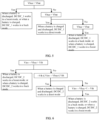
- FIG. 6 is a schematic diagram of control logic of an electrical energy storage system 100 according to an embodiment of this application.
- Vinv represents a rated voltage of a second terminal of any second DC/DC converter (in other words, a rated voltage at a first interface F)
- Vbus represents a rated voltage of a first terminal of any second DC/DC converter (in other words, a rated voltage of a second terminal of a first DC/DC converter)
- Vth represents a preset threshold voltage.
- control logic of the second DC/DC converter is as follows:
- the second DC/DC converter When Vinv - Vbus > Vth, if a battery pack is discharged, the second DC/DC converter is configured to boost Vbus to output Vinv; or if a battery pack is charged, the second DC/DC converter is configured to buck Vinv to output Vbus.
- the second DC/DC converter works in a direct mode.
- the second DC/DC converter When Vinv - Vbus ⁇ -Vth, if a battery pack is discharged, the second DC/DC converter is configured to buck Vbus to output Vinv; or if a battery pack is charged, the second DC/DC converter is configured to boost Vinv to output Vbus.
- a specific value of Vth may be determined based on practice.
- the specific value of Vth may be related to an input voltage range of the first DC/DC converter.
- Vinv falls within the input voltage range of the first DC/DC converter. Therefore, the second DC/DC converter works in a direct mode, and Vinv may be directly used as an input voltage of the second DC/DC converter.
- Vth is 5 V or 10 V.
- Vinv 1000 V
- Vbus 350 V
- Vth 10 V. That is, Vinv - Vbus > Vth.
- the second DC/DC converter is configured to boost Vbus to output Vinv; or when the battery pack is charged, the second DC/DC converter is configured to buck Vinv to output Vbus.
- FIG. 7 is a schematic diagram depicting a structure of an energy storage power supply system according to an embodiment of this application.
- the energy storage power supply system includes a schematic diagram depicting structures of an electrical energy storage system 100 and a power generation system 200.
- the power generation system 200 in FIG. 7 is a photovoltaic power generation system.
- the power generation system 200 includes a photovoltaic inverter.
- the photovoltaic inverter includes an MPPT module and a DC/AC converter.
- the inverter in FIG. 4 may be the DC/AC converter, and the voltage regulator module may be the MPPT module.
- a first terminal A1 of the DC/AC converter is configured to connect to a first interface F of the electrical energy storage system 100, and the first terminal A1 of the DC/AC converter is further configured to connect to the MPPT module to receive a direct current from a photovoltaic (PV) component.
- a second terminal A2 of the DC/AC converter is configured to connect to an alternating current load or an alternating current power grid.
- the DC/AC converter may receive a direct current output by the MPPT module, implement DC/AC conversion in a direction from the first terminal A1 to the second terminal A2, and supply an obtained alternating current to the alternating current load.
- the first terminal A1 of the DC/AC converter is further configured to output a direct current to the electrical energy storage system 100 through the first interface F.
- the DC/AC converter may alternatively implement AC/DC conversion in a direction from the second terminal A2 to the first terminal A1.
- an alternating current input by the alternating current power grid may be converted into a direct current, and the direct current is supplied to the electrical energy storage system 100.
- a function of the electrical energy storage system 100 is similar to that in FIG. 4 .
- details are not described herein again.
- the disclosed system, apparatus, and method may be implemented in other manners.
- the described apparatus embodiment is merely an example.
- the unit division is merely logical function division and may be other division in actual implementation.
- a plurality of units or components may be combined or integrated into another system, or some features may be ignored or not performed.
- the displayed or discussed mutual couplings or direct couplings or communication connections may be implemented through some interfaces.
- the indirect couplings or communication connections between the apparatuses or units may be implemented in electronic, mechanical, or other forms.
- the units described as separate parts may or may not be physically separate, and parts displayed as units may or may not be physical units, may be located in one position, or may be distributed on a plurality of network units. Some or all of the units may be selected depending on actual requirements to achieve the objectives of the solutions in the embodiments.
- the functions When the functions are implemented in a form of a software functional unit and sold or used as an independent product, the functions may be stored in a computer-readable storage medium. Based on such an understanding, the technical solutions of this application essentially, or the part contributing to the conventional technology, or some of the technical solutions may be implemented in a form of a software product.
- the computer software product is stored in a storage medium, and includes several instructions for instructing a computer device (which may be a personal computer, a server, or a network device) to perform all or some of the steps of the methods described in the embodiments of this application.
- the foregoing storage medium includes any medium that can store program code, such as a USB flash drive, a removable hard disk, a read-only memory (Read-Only Memory, ROM), a random access memory (Random Access Memory, RAM), a magnetic disk, or an optical disc.
- program code such as a USB flash drive, a removable hard disk, a read-only memory (Read-Only Memory, ROM), a random access memory (Random Access Memory, RAM), a magnetic disk, or an optical disc.
Landscapes
- Engineering & Computer Science (AREA)
- Power Engineering (AREA)
- Charge And Discharge Circuits For Batteries Or The Like (AREA)
- Supply And Distribution Of Alternating Current (AREA)
Priority Applications (1)
| Application Number | Priority Date | Filing Date | Title |
|---|---|---|---|
| EP24189308.0A EP4478583A3 (de) | 2020-06-17 | 2020-06-17 | Elektrisches energiespeichersystem und energiespeichersystem |
Applications Claiming Priority (3)
| Application Number | Priority Date | Filing Date | Title |
|---|---|---|---|
| PCT/CN2020/096468 WO2021253257A1 (zh) | 2020-06-17 | 2020-06-17 | 电力储能系统以及储能供电系统 |
| EP20940597.6A EP4027476B1 (de) | 2020-06-17 | 2020-06-17 | Elektrisches energiespeichersystem mit mehreren akkupacks |
| EP24189308.0A EP4478583A3 (de) | 2020-06-17 | 2020-06-17 | Elektrisches energiespeichersystem und energiespeichersystem |
Related Parent Applications (2)
| Application Number | Title | Priority Date | Filing Date |
|---|---|---|---|
| EP20940597.6A Division EP4027476B1 (de) | 2020-06-17 | 2020-06-17 | Elektrisches energiespeichersystem mit mehreren akkupacks |
| EP20940597.6A Division-Into EP4027476B1 (de) | 2020-06-17 | 2020-06-17 | Elektrisches energiespeichersystem mit mehreren akkupacks |
Publications (2)
| Publication Number | Publication Date |
|---|---|
| EP4478583A2 true EP4478583A2 (de) | 2024-12-18 |
| EP4478583A3 EP4478583A3 (de) | 2025-03-19 |
Family
ID=77712091
Family Applications (2)
| Application Number | Title | Priority Date | Filing Date |
|---|---|---|---|
| EP20940597.6A Active EP4027476B1 (de) | 2020-06-17 | 2020-06-17 | Elektrisches energiespeichersystem mit mehreren akkupacks |
| EP24189308.0A Pending EP4478583A3 (de) | 2020-06-17 | 2020-06-17 | Elektrisches energiespeichersystem und energiespeichersystem |
Family Applications Before (1)
| Application Number | Title | Priority Date | Filing Date |
|---|---|---|---|
| EP20940597.6A Active EP4027476B1 (de) | 2020-06-17 | 2020-06-17 | Elektrisches energiespeichersystem mit mehreren akkupacks |
Country Status (6)
| Country | Link |
|---|---|
| US (2) | US11749995B2 (de) |
| EP (2) | EP4027476B1 (de) |
| CN (3) | CN118693878A (de) |
| AU (1) | AU2020454251A1 (de) |
| ES (1) | ES3015245T3 (de) |
| WO (1) | WO2021253257A1 (de) |
Families Citing this family (3)
| Publication number | Priority date | Publication date | Assignee | Title |
|---|---|---|---|---|
| EP4383496A1 (de) | 2022-12-08 | 2024-06-12 | Hitachi Energy Ltd | Energiespeichersystem für ein gleichstromübertragungssystem und verfahren zum energieaustausch mit einer gleichstromübertragung |
| WO2024228575A1 (ko) * | 2023-05-04 | 2024-11-07 | 엘지이노텍 주식회사 | 배터리 모듈 |
| CN116742704A (zh) * | 2023-06-15 | 2023-09-12 | 横店集团东磁股份有限公司 | 一种智能家庭储能系统及其实现方法 |
Family Cites Families (15)
| Publication number | Priority date | Publication date | Assignee | Title |
|---|---|---|---|---|
| US8319471B2 (en) | 2006-12-06 | 2012-11-27 | Solaredge, Ltd. | Battery power delivery module |
| US9088178B2 (en) | 2006-12-06 | 2015-07-21 | Solaredge Technologies Ltd | Distributed power harvesting systems using DC power sources |
| US7911079B2 (en) * | 2007-07-31 | 2011-03-22 | Caterpillar Inc | Electrical system architecture having high voltage bus |
| CN103178553B (zh) * | 2013-03-08 | 2015-10-28 | 沃太能源南通有限公司 | 一种家用混合供电系统 |
| KR20160023169A (ko) | 2014-08-21 | 2016-03-03 | 주식회사 엘지씨엔에스 | 에너지 저장 시스템의 전력 관리 장치 |
| CN204230948U (zh) * | 2014-09-30 | 2015-03-25 | 深圳市盛弘电气有限公司 | 一种新能源馈电式充放电机 |
| CN107404149A (zh) * | 2017-09-04 | 2017-11-28 | 广州泓淮能源科技有限公司 | 一种基于直流系统的蓄电池并联供电系统 |
| US11394236B2 (en) * | 2017-10-02 | 2022-07-19 | Enatel | Modular power systems |
| WO2019102565A1 (ja) * | 2017-11-24 | 2019-05-31 | Tdk株式会社 | 直流給電システム |
| US10811993B2 (en) * | 2017-12-15 | 2020-10-20 | Ess Tech, Inc. | Power conversion system and method |
| US10951040B2 (en) * | 2018-04-27 | 2021-03-16 | Nextracker Inc. | DC/DC converter for distributed storage and solar systems |
| US11387659B2 (en) * | 2018-06-26 | 2022-07-12 | Texas Instruments Incorporated | Switching mode charger with pass through mode |
| CN109193614B (zh) * | 2018-08-29 | 2020-01-24 | 微控物理储能研究开发(深圳)有限公司 | 飞轮储能再生制动能量回馈系统及其控制方法 |
| CN109921409B (zh) * | 2019-04-16 | 2024-01-16 | 清华大学 | 一种建筑全直流供电和蓄电系统及控制方法 |
| CN110912235B (zh) * | 2019-12-13 | 2021-11-02 | 阳光电源股份有限公司 | 储能系统及其均流方法 |
-
2020
- 2020-06-17 AU AU2020454251A patent/AU2020454251A1/en active Pending
- 2020-06-17 CN CN202410719647.3A patent/CN118693878A/zh active Pending
- 2020-06-17 EP EP20940597.6A patent/EP4027476B1/de active Active
- 2020-06-17 EP EP24189308.0A patent/EP4478583A3/de active Pending
- 2020-06-17 CN CN202080012506.8A patent/CN113424388A/zh active Pending
- 2020-06-17 CN CN202311021305.6A patent/CN117200289A/zh active Pending
- 2020-06-17 WO PCT/CN2020/096468 patent/WO2021253257A1/zh not_active Ceased
- 2020-06-17 ES ES20940597T patent/ES3015245T3/es active Active
-
2022
- 2022-07-21 US US17/870,790 patent/US11749995B2/en active Active
-
2023
- 2023-07-31 US US18/362,728 patent/US12212142B2/en active Active
Also Published As
| Publication number | Publication date |
|---|---|
| AU2020454251A1 (en) | 2022-04-21 |
| US12212142B2 (en) | 2025-01-28 |
| CN118693878A (zh) | 2024-09-24 |
| CN113424388A (zh) | 2021-09-21 |
| US11749995B2 (en) | 2023-09-05 |
| EP4027476A4 (de) | 2022-12-07 |
| US20230378757A1 (en) | 2023-11-23 |
| CN117200289A (zh) | 2023-12-08 |
| EP4027476A1 (de) | 2022-07-13 |
| EP4027476B1 (de) | 2025-01-15 |
| EP4478583A3 (de) | 2025-03-19 |
| ES3015245T3 (en) | 2025-04-30 |
| US20220360086A1 (en) | 2022-11-10 |
| WO2021253257A1 (zh) | 2021-12-23 |
Similar Documents
| Publication | Publication Date | Title |
|---|---|---|
| US12212142B2 (en) | Electrical energy storage system and energy storage system | |
| CN109428393B (zh) | 不间断电源系统和方法 | |
| EP3148037A1 (de) | Energiespeichersystem | |
| Cvetkovic et al. | A testbed for experimental validation of a low-voltage DC nanogrid for buildings | |
| KR101369633B1 (ko) | 전력 저장 시스템 및 그 제어방법 | |
| US10547173B2 (en) | Power generation system | |
| CN102074970A (zh) | 能量管理系统和包括该能量管理系统的并网能量存储系统 | |
| CN103155335A (zh) | 用于能量存储系统的功率转换系统及其控制方法 | |
| CN112383092B (zh) | 一种能量调度方法、装置及系统 | |
| CN106159980B (zh) | 发电系统和能量管理方法 | |
| CN113098066B (zh) | 一种功率调节方法、功率调节装置及终端设备 | |
| CN107872065B (zh) | 一种电网储能系统出力的控制方法及装置 | |
| AU2022316768B2 (en) | Off-grid power supply system and control method thereof | |
| CN115833210A (zh) | 一种多机并联储能系统及其充放电控制方法 | |
| KR101337576B1 (ko) | Soc 관리를 위한 방법 및 시스템 | |
| KR101677835B1 (ko) | 에너지 저장 시스템의 배터리 상태 측정 방법 | |
| CN115765131A (zh) | 充电装置和充电控制方法 | |
| CN118944165B (zh) | 基于交直流混合母线架构的储充系统及其工作方法 | |
| EP3711130A1 (de) | System zur speisung von zusatzlasten eines energiespeichersystems | |
| CN110224389B (zh) | 一种基于自律式浮动电压运行策略的直流微电网系统 | |
| KR20210010753A (ko) | 직류 공통 방식을 이용한 하이브리드 신재생 에너지 시스템 | |
| Gonschorowski et al. | Adaptive Frequency-Based Power Management for Off-Grid Hybrid Photovoltaic Converters | |
| JP2024017513A (ja) | 分散型電源システム及び分散型電源の制御方法 | |
| CN109599898B (zh) | 提高分布式电源消纳的控制方法及装置 | |
| KR102668411B1 (ko) | Dc 버스 전압의 자율복원 능력을 갖는 dcmg의 비중앙 드룹 제어 시스템 |
Legal Events
| Date | Code | Title | Description |
|---|---|---|---|
| PUAI | Public reference made under article 153(3) epc to a published international application that has entered the european phase |
Free format text: ORIGINAL CODE: 0009012 |
|
| STAA | Information on the status of an ep patent application or granted ep patent |
Free format text: STATUS: THE APPLICATION HAS BEEN PUBLISHED |
|
| AC | Divisional application: reference to earlier application |
Ref document number: 4027476 Country of ref document: EP Kind code of ref document: P |
|
| AK | Designated contracting states |
Kind code of ref document: A2 Designated state(s): AL AT BE BG CH CY CZ DE DK EE ES FI FR GB GR HR HU IE IS IT LI LT LU LV MC MK MT NL NO PL PT RO RS SE SI SK SM TR |
|
| REG | Reference to a national code |
Ref country code: DE Ref legal event code: R079 Free format text: PREVIOUS MAIN CLASS: H02J0007000000 Ipc: H02J0003320000 |
|
| PUAL | Search report despatched |
Free format text: ORIGINAL CODE: 0009013 |
|
| AK | Designated contracting states |
Kind code of ref document: A3 Designated state(s): AL AT BE BG CH CY CZ DE DK EE ES FI FR GB GR HR HU IE IS IT LI LT LU LV MC MK MT NL NO PL PT RO RS SE SI SK SM TR |
|
| RIC1 | Information provided on ipc code assigned before grant |
Ipc: H02J 7/00 20060101ALI20250213BHEP Ipc: H02J 3/38 20060101ALI20250213BHEP Ipc: H02J 3/32 20060101AFI20250213BHEP |
|
| STAA | Information on the status of an ep patent application or granted ep patent |
Free format text: STATUS: REQUEST FOR EXAMINATION WAS MADE |
|
| 17P | Request for examination filed |
Effective date: 20250919 |
|
| STAA | Information on the status of an ep patent application or granted ep patent |
Free format text: STATUS: EXAMINATION IS IN PROGRESS |
|
| 17Q | First examination report despatched |
Effective date: 20251216 |