WO2021253257A1 - 电力储能系统以及储能供电系统 - Google Patents
电力储能系统以及储能供电系统 Download PDFInfo
- Publication number
- WO2021253257A1 WO2021253257A1 PCT/CN2020/096468 CN2020096468W WO2021253257A1 WO 2021253257 A1 WO2021253257 A1 WO 2021253257A1 CN 2020096468 W CN2020096468 W CN 2020096468W WO 2021253257 A1 WO2021253257 A1 WO 2021253257A1
- Authority
- WO
- WIPO (PCT)
- Prior art keywords
- converter
- vbus
- power
- power generation
- energy storage
- Prior art date
Links
- 238000004146 energy storage Methods 0.000 title claims abstract description 61
- 238000010248 power generation Methods 0.000 claims abstract description 105
- 238000006243 chemical reaction Methods 0.000 claims description 20
- 238000010586 diagram Methods 0.000 description 15
- 230000006870 function Effects 0.000 description 11
- 238000000034 method Methods 0.000 description 7
- 230000000087 stabilizing effect Effects 0.000 description 7
- 230000006641 stabilisation Effects 0.000 description 5
- 238000011105 stabilization Methods 0.000 description 5
- 230000008878 coupling Effects 0.000 description 3
- 238000010168 coupling process Methods 0.000 description 3
- 238000005859 coupling reaction Methods 0.000 description 3
- 238000004891 communication Methods 0.000 description 2
- 238000007599 discharging Methods 0.000 description 2
- 230000005611 electricity Effects 0.000 description 2
- 238000011156 evaluation Methods 0.000 description 2
- 238000004519 manufacturing process Methods 0.000 description 2
- 238000012544 monitoring process Methods 0.000 description 2
- 238000012545 processing Methods 0.000 description 2
- 206010068065 Burning mouth syndrome Diseases 0.000 description 1
- 230000002457 bidirectional effect Effects 0.000 description 1
- 230000005540 biological transmission Effects 0.000 description 1
- 238000013461 design Methods 0.000 description 1
- 238000005516 engineering process Methods 0.000 description 1
- 230000003287 optical effect Effects 0.000 description 1
- 238000006467 substitution reaction Methods 0.000 description 1
Images


Classifications
-
- H—ELECTRICITY
- H02—GENERATION; CONVERSION OR DISTRIBUTION OF ELECTRIC POWER
- H02J—CIRCUIT ARRANGEMENTS OR SYSTEMS FOR SUPPLYING OR DISTRIBUTING ELECTRIC POWER; SYSTEMS FOR STORING ELECTRIC ENERGY
- H02J3/00—Circuit arrangements for ac mains or ac distribution networks
- H02J3/28—Arrangements for balancing of the load in a network by storage of energy
- H02J3/32—Arrangements for balancing of the load in a network by storage of energy using batteries with converting means
-
- H—ELECTRICITY
- H02—GENERATION; CONVERSION OR DISTRIBUTION OF ELECTRIC POWER
- H02J—CIRCUIT ARRANGEMENTS OR SYSTEMS FOR SUPPLYING OR DISTRIBUTING ELECTRIC POWER; SYSTEMS FOR STORING ELECTRIC ENERGY
- H02J3/00—Circuit arrangements for ac mains or ac distribution networks
- H02J3/38—Arrangements for parallely feeding a single network by two or more generators, converters or transformers
- H02J3/381—Dispersed generators
-
- H—ELECTRICITY
- H02—GENERATION; CONVERSION OR DISTRIBUTION OF ELECTRIC POWER
- H02J—CIRCUIT ARRANGEMENTS OR SYSTEMS FOR SUPPLYING OR DISTRIBUTING ELECTRIC POWER; SYSTEMS FOR STORING ELECTRIC ENERGY
- H02J7/00—Circuit arrangements for charging or depolarising batteries or for supplying loads from batteries
- H02J7/0013—Circuit arrangements for charging or depolarising batteries or for supplying loads from batteries acting upon several batteries simultaneously or sequentially
- H02J7/0014—Circuits for equalisation of charge between batteries
- H02J7/0018—Circuits for equalisation of charge between batteries using separate charge circuits
-
- H—ELECTRICITY
- H02—GENERATION; CONVERSION OR DISTRIBUTION OF ELECTRIC POWER
- H02J—CIRCUIT ARRANGEMENTS OR SYSTEMS FOR SUPPLYING OR DISTRIBUTING ELECTRIC POWER; SYSTEMS FOR STORING ELECTRIC ENERGY
- H02J7/00—Circuit arrangements for charging or depolarising batteries or for supplying loads from batteries
- H02J7/0068—Battery or charger load switching, e.g. concurrent charging and load supply
-
- H—ELECTRICITY
- H02—GENERATION; CONVERSION OR DISTRIBUTION OF ELECTRIC POWER
- H02J—CIRCUIT ARRANGEMENTS OR SYSTEMS FOR SUPPLYING OR DISTRIBUTING ELECTRIC POWER; SYSTEMS FOR STORING ELECTRIC ENERGY
- H02J2207/00—Indexing scheme relating to details of circuit arrangements for charging or depolarising batteries or for supplying loads from batteries
- H02J2207/20—Charging or discharging characterised by the power electronics converter
-
- H—ELECTRICITY
- H02—GENERATION; CONVERSION OR DISTRIBUTION OF ELECTRIC POWER
- H02J—CIRCUIT ARRANGEMENTS OR SYSTEMS FOR SUPPLYING OR DISTRIBUTING ELECTRIC POWER; SYSTEMS FOR STORING ELECTRIC ENERGY
- H02J2300/00—Systems for supplying or distributing electric power characterised by decentralized, dispersed, or local generation
- H02J2300/20—The dispersed energy generation being of renewable origin
- H02J2300/22—The renewable source being solar energy
- H02J2300/24—The renewable source being solar energy of photovoltaic origin
- H02J2300/26—The renewable source being solar energy of photovoltaic origin involving maximum power point tracking control for photovoltaic sources
-
- H—ELECTRICITY
- H02—GENERATION; CONVERSION OR DISTRIBUTION OF ELECTRIC POWER
- H02J—CIRCUIT ARRANGEMENTS OR SYSTEMS FOR SUPPLYING OR DISTRIBUTING ELECTRIC POWER; SYSTEMS FOR STORING ELECTRIC ENERGY
- H02J2300/00—Systems for supplying or distributing electric power characterised by decentralized, dispersed, or local generation
- H02J2300/20—The dispersed energy generation being of renewable origin
- H02J2300/28—The renewable source being wind energy
-
- H—ELECTRICITY
- H02—GENERATION; CONVERSION OR DISTRIBUTION OF ELECTRIC POWER
- H02J—CIRCUIT ARRANGEMENTS OR SYSTEMS FOR SUPPLYING OR DISTRIBUTING ELECTRIC POWER; SYSTEMS FOR STORING ELECTRIC ENERGY
- H02J7/00—Circuit arrangements for charging or depolarising batteries or for supplying loads from batteries
- H02J7/34—Parallel operation in networks using both storage and other dc sources, e.g. providing buffering
- H02J7/35—Parallel operation in networks using both storage and other dc sources, e.g. providing buffering with light sensitive cells
Definitions
- This application relates to the field of power supply, in particular to electric energy storage systems and energy storage power supply systems.
- the electric energy storage system can store the electric energy generated by the power generation system in the battery, and draw electricity from the battery when needed.
- the power generation system may be a new energy power generation system, such as a wind power generation system or a photovoltaic power generation system.
- the power generation system can output direct current or alternating current.
- DC power can be provided to the power storage system for storage, and AC power can be provided to the AC grid or AC load.
- the AC voltage output by the power generation system includes different voltage levels.
- AC voltage levels can generally include single-phase 220Vac and three-phase 380Vac.
- AC/DC alternating current to direct current
- the magnitude of the DC voltage is also very different.
- a single-phase 220Vac corresponds to a DC voltage of 311Vdc
- a three-phase 380Vac corresponds to a DC voltage of 537Vdc.
- Vac represents the maximum amplitude of the AC voltage
- Vdc represents the magnitude of the DC voltage.
- the direct current to direct current (DC/DC) converter in the power storage system is used to receive the direct current output by the power generation system, and after the direct current voltage is converted, the direct current is input into the battery pack for energy storage. Therefore, the DC/DC converter needs to be designed to adapt its input voltage range to the output voltage range of the power generation system.
- the input voltage range of the DC/DC converter in the electric energy storage system is usually designed to match the voltage level of the alternating current of the power generation system.
- the AC voltage level of the power generation system changes, for example, from single-phase 220Vac to three-phase 380Vac, since the DC/DC input voltage range is designed to support single-phase 220Vac, it cannot support three-phase 220Vac.
- the input voltage range corresponding to the phase 380Vac causes the electric energy storage system to be incompatible with different voltage levels, which affects the application flexibility of the electric energy storage system.
- This application provides an electric energy storage system and an energy storage power supply system, which can improve the application flexibility of the electric energy storage system.
- a power storage system including: M battery packs; M first DC-to-DC DC/DC converters, the first terminals of the M first DC/DC converters are connected to The M battery packs are connected, the M first DC/DC converters are divided into N first DC/DC converter sets, M is an integer greater than 1, N is an integer greater than 0; Two DC/DC converters, corresponding to the N first DC/DC converter sets one-to-one, and the first end of each second DC/DC converter corresponds to one of the first DC/DC converter sets The second end of the first DC/DC converter is connected, and the second end of each second DC/DC converter is connected to the first interface of the power storage system, and the first interface is used to receive from the power generation system Direct current or direct current output to the power generation system, N is an integer greater than 1.
- the power storage system includes two types of DC/DC converters, where N second DC/DC converters are arranged between the power generation system and the first DC/DC.
- N second DC/DC converters are arranged between the power generation system and the first DC/DC.
- the second DC/DC converter can be used for voltage conversion of the input voltage of the power generation system.
- the output voltage is adapted to the input range of the first DC/DC converter.
- the second DC/DC converter may perform voltage conversion on the voltage input by the first DC/DC, so that the voltage range output to the power generation system is adapted to the voltage level of the power generation system. Therefore, the electric energy storage system can be compatible with different voltage levels of the power generation system, and the application flexibility of the electric energy storage system is improved.
- the electric energy storage system can be compatible with different voltage levels of the power generation system, the electric energy storage system can be adapted to inverters of different voltage levels in the power generation system.
- a unified standard can be used to produce power energy storage systems corresponding to power generation systems of different voltage levels. Increase productivity.
- the second DC/DC converter when Vinv-Vbus>Vth and the battery pack is discharged, the second DC/DC converter is used to boost Vbus to Output Vinv; in the case of Vinv-Vbus>Vth and the battery pack is charged, the second DC/DC converter is used to step down Vinv to output Vbus; where Vinv represents the second DC/DC conversion
- Vbus represents the rated voltage of the first terminal of the second DC/DC converter
- Vth represents the preset threshold voltage.
- the second DC/DC converter works in a through mode; where Vinv represents all For the rated voltage of the second terminal of the second DC/DC converter, Vbus represents the rated voltage of the first terminal of the second DC/DC converter, and Vth represents a preset threshold voltage.
- the second DC/DC converter when Vinv-Vbus ⁇ -Vth and the battery pack is discharged, the second DC/DC converter is used to perform step-down processing on Vbus, To output Vinv; in the case of Vinv-Vbus>Vth and the battery pack is charged, the second DC/DC converter is used to boost Vinv to output Vbus; where Vinv represents the second DC/DC The rated voltage of the second terminal of the converter, Vbus represents the rated voltage of the first terminal of the second DC/DC converter, and Vth represents a preset threshold voltage.
- the first DC/DC converter when Vbus>Vbat and the battery pack is discharged, the first DC/DC converter is used to boost Vbat to output Vbus ; In the case of Vbus>Vbat and the battery pack is charged, the first DC/DC converter is used to step down Vbus to output Vbat; where Vbus represents the first of the second DC/DC converter The rated voltage of the terminal, Vbat represents the rated voltage of the anode of the battery pack.
- the first DC/DC converter works in a through mode; where Vbus represents the second DC/ The voltage at the first terminal of the DC converter, Vbat represents the rated voltage of the anode of the battery pack.
- the first DC/DC converter when Vbus ⁇ Vbat and the battery pack is discharged, the first DC/DC converter is used to step down Vbat to output Vbus ; In the case of Vbus ⁇ Vbat and the battery pack is charged, the first DC/DC converter is used to boost Vbus to output Vbat; where Vbus represents the first of the second DC/DC converter The terminal voltage, Vbat represents the rated voltage of the anode of the battery pack.
- the power generation system includes an inverter, and the first end of the inverter is connected to the first interface of the power storage system, so The second end of the inverter is used to connect to an AC load or an AC power grid.
- the power generation system is a photovoltaic power generation system
- the power generation system includes a photovoltaic inverter
- the photovoltaic inverter includes a maximum power point tracking MPPT module
- a DC/AC converter the inverter is the DC/AC converter; the first end of the DC/AC converter is used to connect to the first interface of the power storage system, and the DC The first end of the /AC converter is also used to connect to the MPPT module, and the second end of the DC/AC converter is used to connect to an AC load or an AC power grid.
- an energy storage power supply system in a second aspect, includes the electric energy storage system and the power generation system as described in the first aspect.
- Fig. 1 is a schematic diagram of an application scenario of an embodiment of the present application.
- Fig. 2 is a schematic diagram of an application scenario of an embodiment of the present application.
- Fig. 3 is a schematic diagram of an application scenario of an embodiment of the present application.
- Fig. 4 is a schematic structural diagram of an energy storage power supply system according to an embodiment of the present application.
- FIG. 5 is a schematic diagram of the control logic of the power storage system 100 according to an embodiment of the present application.
- FIG. 6 is a schematic diagram of the control logic of the power energy storage system 100 according to an embodiment of the present application.
- Fig. 7 is a schematic structural diagram of an energy storage power supply system according to an embodiment of the present application.
- Fig. 1 is a schematic diagram of an application scenario of an embodiment of the present application.
- the power generation system 200 can generate alternating current or direct current, and provide the alternating current to an alternating current grid or an alternating current load.
- the power generation system 200 may also provide the generated direct current power to the power storage system 100, and the power storage system 100 stores electrical energy.
- the power storage system 100 can output DC power to the power generation system 200, and the DC power is processed by the (direct current to alternating current, DC/AC) converter in the power generation system 200 to obtain AC power , And provide to AC load or AC grid.
- DC/AC direct current to alternating current
- the power generation system 200 may be a new energy power generation system, such as a wind power generation system or a photovoltaic power generation system.
- the power generation system 200 includes a power generation module, and the power generation module can generate direct current or alternating current.
- the power generation module in the wind power generation system usually generates AC power
- the power generation module in the photovoltaic power generation system usually generates DC power.
- the power generation system 200 further includes a voltage stabilization module, which can realize the function of stabilizing the voltage output by the power generation module. If the current output by the power generation module is alternating current, the voltage stabilizing module is also used to convert the alternating current to direct current.
- the voltage stabilization module in a wind power generation system is usually an AC/DC converter
- the voltage stabilization module in a photovoltaic power generation system is usually a DC/DC converter.
- the DC/DC converter can be set in the maximum power point tracking (MPPT) module of the photovoltaic inverter (see Figure 2).
- MPPT maximum power point tracking
- the power generation system 200 further includes an inverter.
- the inverter is usually arranged between the voltage stabilizing module and the AC load (or the AC power grid), and it can realize the conversion from DC to AC.
- the inverter can also be called a DC/AC converter.
- the inverter includes a first terminal A1 and a second terminal A2.
- the first terminal A1 is used to receive DC power
- the second terminal A2 is used to connect to an AC load or an AC power grid.
- the inverter can realize DC/AC conversion from the first end A1 to the second end A2, and provide the obtained AC power to the AC load or AC power grid.
- the first terminal A1 of the inverter is also used to connect to the first interface F of the electric energy storage system 100 to output direct current to the electric energy storage system 100.
- the inverter can also implement AC/DC conversion from the second end A2 to the first end A1.
- the AC power input from the AC power grid may be converted into DC power and provided to the power storage system 100.
- the inverter may be a DC/AC converter in a photovoltaic inverter (see FIG. 2).
- Fig. 2 is a schematic diagram of an application scenario of an embodiment of the present application.
- the scenario in Figure 2 can be applied to the scenario of photovoltaic power generation.
- the application scenario includes a power generation system 200 and a power storage system 100.
- the power generation system 200 includes a photovoltaic (PV) module and a photovoltaic inverter.
- PV photovoltaic
- the photovoltaic inverter is a special inverter designed for photovoltaic power generation systems.
- the core of photovoltaic power generation is to use photovoltaic modules (ie, solar panels) to convert solar energy into electrical energy.
- photovoltaic modules ie, solar panels
- photovoltaic modules can only generate direct current, it is necessary to convert direct current to alternating current through a photovoltaic inverter to facilitate the transmission and utilization of electricity.
- photovoltaic inverters Compared with ordinary inverters, in addition to DC/AC converters, photovoltaic inverters also include MPPT modules.
- the MPPT module includes a DC/DC converter.
- the MPPT module can be used to track the highest voltage and current value, so that the power generation system 200 can output current at the maximum power.
- the MPPT module and the DC/DC module in the photovoltaic inverter can be installed in the same packaged device or in different packaged devices.
- the MPPT can perform voltage conversion on the direct current generated by the PV module and then output it to the power energy storage system 100.
- the first end A1 of the DC/AC converter can be used to connect the MPPT module and the power storage system 100, and the second end A2 is used to connect to the AC grid or AC load to convert the DC power output by the MPPT module or the power storage system 100 It is AC power and is supplied to AC load or AC grid.
- the power energy storage system 100 generally includes one or more DC/DCs, one or more battery packs, and one or more battery management systems (BMS). Each battery pack corresponds to a BMS. BMS is usually used to implement functions such as dynamic monitoring of battery charging and discharging, battery balancing, and evaluation of battery state of charge.
- BMS battery management systems
- Fig. 3 is a schematic diagram of an application scenario of another embodiment of the present application.
- the scenario in Figure 3 can be applied to the scenario of wind power generation.
- the application scenario includes a power generation system 200 and an electric energy storage system 100.
- the power generation system 200 includes a wind turbine system, an AC/DC converter, and a DC/AC converter (ie, an inverter).
- the fan system is used to generate alternating current.
- the AC/DC converter can be used to convert the alternating current generated by the fan system into direct current and realize the function of voltage stabilization.
- the AC/DC converter can also output direct current to the electric energy storage system 100, so that the electric energy storage system 100 can store electric energy.
- the DC/AC converter can be used to receive the direct current output by the AC/DC converter and convert it to alternating current to provide it to an alternating current load or an alternating current grid.
- the DC/AC converter can also be used to receive the direct current output from the power storage system 100 and convert it to alternating current to provide it to an alternating current load or an alternating current grid.
- FIGS. 1 to 3 are merely examples, and not limitation, and the electric energy storage system and energy storage power supply system of the embodiments of the present application may also be applied to other power generation types of application scenarios.
- Fig. 4 is a schematic structural diagram of an energy storage power supply system according to an embodiment of the present application.
- the energy storage power supply system includes a power generation system 200 and an electric energy storage system 100.
- the power storage system 100 includes: M battery packs, M first DC/DC converters (indicated as DC/DC_1 in the figure), and N second DC/DC converters (in the figure Denoted as DC/DC_2) and M BMS.
- M is an integer greater than 1
- N is an integer greater than zero.
- the M battery packs have a one-to-one correspondence with M BMSs, and each BMS is used to manage a corresponding battery pack. For example, perform functions such as dynamic monitoring of battery charging and discharging of the battery pack, battery balancing, and evaluation of battery state of charge.
- each battery pack corresponds to the M first DC/DC converters in a one-to-one correspondence.
- each battery pack is connected to the first end of the corresponding first DC/DC converter.
- the foregoing M first DC/DC converters may be divided into N first DC/DC converter sets.
- the N first DC/DC converter sets are in one-to-one correspondence with the N second DC/DC converters.
- Each first DC/DC converter set includes one or more first DC/DC converters.
- the number of first DC/DC converters included in different first DC/DC converter sets may be the same or different.
- the foregoing M battery packs are also divided into N battery pack sets.
- the N battery pack sets, the N first DC/DC converter sets, and the N second DC/DC converters have a one-to-one correspondence with each other.
- each second DC/DC converter is connected to the first interface F of the power storage system 100, and the first interface F is used to receive direct current from the power generation system 200 or output direct current to the power generation system 200, N is an integer greater than 1.
- both the first terminal and the second terminal of the above-mentioned first DC/DC converter include positive and negative terminals.
- the positive and negative terminals of the first end of the first DC/DC converter are respectively connected to the anode and the cathode of the battery pack.
- both the first terminal and the second terminal of the second DC/DC converter include positive and negative terminals.
- the first interface F is used to connect the first terminal A1 of the inverter in the power generation system 200.
- Both the first DC/DC converter and the second DC/DC converter can implement bidirectional boost or step-down functions.
- the first DC/DC converter and the second DC/DC converter can also work in a through mode. In the through mode, the first DC/DC converter and the second DC/DC converter do not perform the step-up/step-down function, which is equivalent to a power switch.
- the N second DC/DCs are in a parallel relationship.
- a certain set of the N first DC/DC converter sets includes a plurality of first DC/DC converters
- the plurality of first DC/DC converters in the set are in a parallel relationship.
- the first DC/DC converter may adopt an isolated power conversion mode or a non-isolated power conversion mode.
- the second DC/DC converter may adopt an isolated power conversion mode or a non-isolated power conversion mode.
- isolated power conversion means that a transformer is provided in the DC/DC converter
- non-isolated power conversion means that a transformer is not provided in the DC/DC converter
- battery packs in different battery pack sets may belong to the same model. Or, they can belong to different manufacturers or different models. In other words, the power storage system of the embodiment of the present application can be compatible with different types of battery packs.
- the power generation system 200 includes an inverter (or a DC/AC converter), and the first end A1 of the inverter is connected to the first interface F of the electric energy storage system 100, The second end A2 of the inverter is used to connect to an AC load or an AC power grid.
- the inverter can output DC power to the power energy storage system 100 through the first interface F of the power energy storage system 100.
- the power generation system 200 may be a new energy power generation system, such as a wind power generation system or a photovoltaic power generation system.
- the power generation system 200 may also be connected to an AC power grid. Wherein, the AC power provided by the AC power grid can be rectified by the inverter in the power generation system 200 to obtain DC power, and the DC power is provided to the power storage system 100.
- the power generation system 200 further includes a power generation module and a voltage stabilization module.
- the power generation module is used to generate direct current or alternating current.
- the above-mentioned direct current or alternating current is direct current after passing through the voltage stabilizing module.
- the first terminal A1 of the inverter is used to receive the DC power output by the voltage stabilizing module.
- the inverter can implement DC/AC conversion from the first terminal A1 to the second terminal A2, and provide the obtained AC power to the AC load.
- the inverter can also implement AC/DC conversion from the second end A2 to the first end A1.
- the AC power input from the AC power grid may be converted into DC power and provided to the power storage system 100.
- the inverter may be a DC/AC converter in the photovoltaic inverter.
- the voltage stabilizing module is an MPPT module in a photovoltaic inverter.
- the power storage system includes two types of DC/DC converters, and N second DC/DC converters are arranged between the power generation system 200 and the first DC/DC.
- the second DC/DC converter can be used for voltage conversion of the input voltage of the power generation system , To adapt the output voltage to the input range of the first DC/DC converter.
- the second DC/DC converter may perform voltage conversion on the voltage input by the first DC/DC, so that the voltage range output to the power generation system is adapted to the voltage level of the power generation system. Therefore, the electric energy storage system can be compatible with different voltage levels of the power generation system, and the application flexibility of the electric energy storage system is improved.
- the electric energy storage system can be compatible with different voltage levels of the power generation system, the electric energy storage system can be adapted to inverters of different voltage levels in the power generation system.
- a unified standard can be used to produce power energy storage systems corresponding to power generation systems of different voltage levels. Increase productivity.
- the electric energy storage system adopts a parallel connection of multiple battery packs. Therefore, if a certain battery pack fails, the normal operation of other battery packs will not be affected, and the reliability of the circuit energy storage system can be improved. sex.
- FIG. 5 is a schematic diagram of the control logic of the power storage system 100 according to an embodiment of the present application.
- Vbus represents the rated voltage of the first terminal of any second DC/DC converter (or the rated voltage of the second terminal of the first DC/DC converter), and Vbat represents the rated voltage of the battery pack.
- Voltage or the rated voltage of the first terminal of the first DC/DC converter.
- the rated voltage can refer to the best voltage when the electrical equipment works normally for a long time.
- the control logic of the first DC/DC is as follows.
- Vbus Vbat
- the first DC/DC converter is used to boost Vbat to output Vbus. If the battery pack is charged, the first DC/DC converter is used to step down Vbus to output Vbat.
- the first DC/DC converter works in the through mode.
- Vbus Vbat
- the first DC/DC converter is used to step down Vbat to output Vbus. If the battery pack is charged, the first DC/DC converter is used to boost Vbus to output Vbat.
- FIG. 6 is a schematic diagram of the control logic of the power energy storage system 100 according to an embodiment of the present application.
- Vinv represents the rated voltage of the second terminal of any second DC/DC converter (or the rated voltage at the first interface F)
- Vbus represents any second DC/DC converter
- Vth represents the preset threshold voltage.
- the control logic of the second DC/DC is as follows.
- Vinv-Vbus>Vth if the battery pack is discharged, the second DC/DC converter is used to boost Vbus to output Vinv. If the battery pack is charged, the second DC/DC converter is used to step down Vinv to output Vbus.
- the second DC/DC converter works in the through mode.
- the second DC/DC converter In the case of Vinv-Vbus ⁇ -Vth, if the battery pack is discharged, the second DC/DC converter is used to step down Vbus to output Vinv. If the battery pack is charged, the second DC/DC converter is used to boost Vinv to output Vbus.
- the specific value of Vth can be determined according to practice.
- the specific value of Vth may be related to the input voltage range of the first DC/DC converter.
- Vinv When Vinv ⁇ [Vbus-Vth, Vbus+Vth], it falls into the input voltage range of the first DC/DC converter. Therefore, the second DC/DC converter works in the through mode, and Vinv can be directly used as the input voltage of the second DC/DC converter.
- Vth is 5V or 10V.
- Vinv 1000V
- Vbus 350V
- Vth 10V. That is, Vinv-Vbus>Vth.
- the second DC/DC converter is used to boost Vbus to output Vinv.
- the second DC/DC converter is used to step-down Vinv to output Vbus.
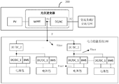
- Fig. 7 is a schematic structural diagram of an energy storage power supply system according to an embodiment of the present application.
- the energy storage power supply system includes: a schematic structural diagram of an electric energy storage system 100 and a power generation system 200.
- the power generation system 200 in FIG. 7 is a photovoltaic power generation system.
- the power generation system 200 includes a photovoltaic inverter, which includes an MPPT module and a DC/AC converter.
- the inverter in Fig. 4 may be the DC/AC converter, and the voltage stabilizing module may be an MPPT module.
- the first terminal A1 of the DC/AC converter is used to connect to the first interface F of the power storage system 100, and the first terminal A1 of the DC/AC converter is also used to connect to the MPPT module to receive the photovoltaic ( PV) The direct current of the module.
- the second end A2 of the DC/AC converter is used to connect to an AC load or an AC power grid.
- the DC/AC converter can receive the DC power output by the MPPT module, realize the DC/AC conversion in the direction from the first end A1 to the second end A2, and provide the obtained AC power to the AC load.
- the first terminal A1 of the DC/AC converter is also used to output direct current to the power energy storage system 100 through the first interface F.
- the DC/AC converter can also implement AC/DC conversion in the direction from the second end A2 to the first end A1.
- the AC power input from the AC power grid may be converted into DC power and provided to the power storage system 100.
- the function of the power storage system 100 is similar to that in FIG.
- the disclosed system, device, and method can be implemented in other ways.
- the device embodiments described above are merely illustrative, for example, the division of the units is only a logical function division, and there may be other divisions in actual implementation, for example, multiple units or components can be combined or It can be integrated into another system, or some features can be ignored or not implemented.
- the displayed or discussed mutual coupling or direct coupling or communication connection may be indirect coupling or communication connection through some interfaces, devices or units, and may be in electrical, mechanical or other forms.
- the units described as separate components may or may not be physically separated, and the components displayed as units may or may not be physical units, that is, they may be located in one place, or they may be distributed on multiple network units. Some or all of the units may be selected according to actual needs to achieve the objectives of the solutions of the embodiments.
- the functional units in the various embodiments of the present application may be integrated into one processing unit, or each unit may exist alone physically, or two or more units may be integrated into one unit.
- the function is implemented in the form of a software functional unit and sold or used as an independent product, it can be stored in a computer readable storage medium.
- the technical solution of this application essentially or the part that contributes to the existing technology or the part of the technical solution can be embodied in the form of a software product, and the computer software product is stored in a storage medium, including Several instructions are used to make a computer device (which may be a personal computer, a server, or a network device, etc.) execute all or part of the steps of the methods described in the various embodiments of the present application.
- the aforementioned storage media include: U disk, mobile hard disk, read-only memory (Read-Only Memory, ROM), random access memory (Random Access Memory, RAM), magnetic disk or optical disk and other media that can store program code .
Abstract
Description
Claims (10)
- 一种电力储能系统,其特征在于,包括:M个电池包;M个第一直流转直流DC/DC变换器,所述M个第一DC/DC变换器的第一端分别与所述M个电池包相连,所述M个第一DC/DC变换器被划分为N个第一DC/DC变换器集合,M为大于1的整数,N为大于0的整数;N个第二DC/DC变换器,与所述N个第一DC/DC变换器集合一一对应,每个第二DC/DC变换器的第一端与其对应的第一DC/DC变换器集合中的第一DC/DC变换器的第二端相连,每个第二DC/DC变换器的第二端与所述电力储能系统的第一接口相连,所述第一接口用于从发电系统接收直流电或向所述发电系统输出直流电,N为大于1的整数。
- 如权利要求1所述的系统,其特征在于,在Vinv-Vbus>Vth且电池包放电的情况下,所述第二DC/DC变换器用于对Vbus进行升压处理,以输出Vinv;在Vinv-Vbus>Vth且电池包充电的情况下,所述第二DC/DC变换器用于对Vinv进行降压处理,以输出Vbus;其中,Vinv表示所述第二DC/DC变换器的第二端的额定电压,Vbus表示所述第二DC/DC变换器的第一端的额定电压,Vth表示预设的阈值电压。
- 如权利要求1或2所述的系统,其特征在于,在-Vth≤Vinv-Vbus<Vth的情况下,所述第二DC/DC变换器工作在直通模式;其中,Vinv表示所述第二DC/DC变换器的第二端的额定电压,Vbus表示所述第二DC/DC变换器的第一端的额定电压,Vth表示预设的阈值电压。
- 如权利要求1至3中任一项所述的系统,其特征在于,在Vinv-Vbus<-Vth且电池包放电的情况下,所述第二DC/DC变换器用于对Vbus进行降压处理,以输出Vinv;在Vinv-Vbus>Vth且电池包充电的情况下,所述第二DC/DC变换器用于对Vinv进行升压处理,以输出Vbus;其中,Vinv表示所述第二DC/DC变换器的第二端的额定电压,Vbus表示所述第二DC/DC变换器的第一端的额定电压,Vth表示预设的阈值电压。
- 如权利要求1至4中任一项所述的系统,其特征在于,在Vbus>Vbat且电池包放电的情况下,所述第一DC/DC变换器用于对Vbat进行升压处理,以输出Vbus;在Vbus>Vbat且电池包充电的情况下,所述第一DC/DC变换器用于对Vbus进行降压处理,以输出Vbat;其中,Vbus表示所述第二DC/DC变换器的第一端的额定电压,Vbat表示电池包阳极的额定电压。
- 如权利要求1至5中任一项所述的系统,其特征在于,在Vbus=Vbat的情况下,所述第一DC/DC变换器工作在直通模式;其中,Vbus表示所述第二DC/DC变换器的第一端的电压,Vbat表示电池包阳极的额定电压。
- 如权利要求1至6中任一项所述的系统,其特征在于,在Vbus<Vbat且电池包放电的情况下,所述第一DC/DC变换器用于对Vbat进行降压处理,以输出Vbus;在Vbus<Vbat且电池包充电的情况下,所述第一DC/DC变换器用于对Vbus进行升压处理,以输出Vbat;其中,Vbus表示所述第二DC/DC变换器的第一端的电压,Vbat表示电池包阳极的额定电压。
- 如权利要求1至7中任一项所述的系统,其特征在于,所述发电系统包括逆变器,所述逆变器的第一端与所述电力储能系统的第一接口相连,所述逆变器的第二端用于与交流负载或交流电网相连。
- 如权利要求8所述的系统,其特征在于,所述发电系统为光伏发电系统,所述发电系统包括光伏逆变器,所述光伏逆变器包括最大功率点追踪MPPT模块和DC/AC变换器,所述逆变器为所述DC/AC变换器;所述DC/AC变换器的第一端用于与所述电力储能系统的第一接口相连,所述DC/AC变换器的第一端还用于与所述MPPT模块相连,所述DC/AC变换器的第二端用于与交流负载或交流电网相连。
- 一种储能供电系统,其特征在于,所述系统包括如权利要求1至9中任一项所述的电力储能系统以及发电系统。
Priority Applications (7)
| Application Number | Priority Date | Filing Date | Title |
|---|---|---|---|
| PCT/CN2020/096468 WO2021253257A1 (zh) | 2020-06-17 | 2020-06-17 | 电力储能系统以及储能供电系统 |
| CN202080012506.8A CN113424388A (zh) | 2020-06-17 | 2020-06-17 | 电力储能系统以及储能供电系统 |
| AU2020454251A AU2020454251A1 (en) | 2020-06-17 | 2020-06-17 | Electrical energy storage system and energy storage system |
| CN202311021305.6A CN117200289A (zh) | 2020-06-17 | 2020-06-17 | 电力储能系统以及储能供电系统 |
| EP20940597.6A EP4027476A4 (en) | 2020-06-17 | 2020-06-17 | ELECTRICITY ENERGY STORAGE SYSTEM AND ENERGY STORAGE POWER SUPPLY SYSTEM |
| US17/870,790 US11749995B2 (en) | 2020-06-17 | 2022-07-21 | Electrical energy storage system and energy storage system |
| US18/362,728 US20230378757A1 (en) | 2020-06-17 | 2023-07-31 | Electrical energy storage system and energy storage system |
Applications Claiming Priority (1)
| Application Number | Priority Date | Filing Date | Title |
|---|---|---|---|
| PCT/CN2020/096468 WO2021253257A1 (zh) | 2020-06-17 | 2020-06-17 | 电力储能系统以及储能供电系统 |
Related Child Applications (1)
| Application Number | Title | Priority Date | Filing Date |
|---|---|---|---|
| US17/870,790 Continuation US11749995B2 (en) | 2020-06-17 | 2022-07-21 | Electrical energy storage system and energy storage system |
Publications (1)
| Publication Number | Publication Date |
|---|---|
| WO2021253257A1 true WO2021253257A1 (zh) | 2021-12-23 |
Family
ID=77712091
Family Applications (1)
| Application Number | Title | Priority Date | Filing Date |
|---|---|---|---|
| PCT/CN2020/096468 WO2021253257A1 (zh) | 2020-06-17 | 2020-06-17 | 电力储能系统以及储能供电系统 |
Country Status (5)
| Country | Link |
|---|---|
| US (2) | US11749995B2 (zh) |
| EP (1) | EP4027476A4 (zh) |
| CN (2) | CN117200289A (zh) |
| AU (1) | AU2020454251A1 (zh) |
| WO (1) | WO2021253257A1 (zh) |
Citations (5)
| Publication number | Priority date | Publication date | Assignee | Title |
|---|---|---|---|---|
| CN103178553A (zh) * | 2013-03-08 | 2013-06-26 | 沃太能源南通有限公司 | 一种家用混合供电系统 |
| CN204230948U (zh) * | 2014-09-30 | 2015-03-25 | 深圳市盛弘电气有限公司 | 一种新能源馈电式充放电机 |
| CN107404149A (zh) * | 2017-09-04 | 2017-11-28 | 广州泓淮能源科技有限公司 | 一种基于直流系统的蓄电池并联供电系统 |
| US20190190400A1 (en) * | 2017-12-15 | 2019-06-20 | Ess Tech, Inc. | Power conversion system and method |
| CN110912235A (zh) * | 2019-12-13 | 2020-03-24 | 阳光电源股份有限公司 | 储能系统及其均流方法 |
Family Cites Families (9)
| Publication number | Priority date | Publication date | Assignee | Title |
|---|---|---|---|---|
| US8319471B2 (en) | 2006-12-06 | 2012-11-27 | Solaredge, Ltd. | Battery power delivery module |
| US9088178B2 (en) | 2006-12-06 | 2015-07-21 | Solaredge Technologies Ltd | Distributed power harvesting systems using DC power sources |
| US7911079B2 (en) * | 2007-07-31 | 2011-03-22 | Caterpillar Inc | Electrical system architecture having high voltage bus |
| KR20160023169A (ko) | 2014-08-21 | 2016-03-03 | 주식회사 엘지씨엔에스 | 에너지 저장 시스템의 전력 관리 장치 |
| WO2019102565A1 (ja) * | 2017-11-24 | 2019-05-31 | Tdk株式会社 | 直流給電システム |
| US10951040B2 (en) * | 2018-04-27 | 2021-03-16 | Nextracker Inc. | DC/DC converter for distributed storage and solar systems |
| US11387659B2 (en) * | 2018-06-26 | 2022-07-12 | Texas Instruments Incorporated | Switching mode charger with pass through mode |
| CN109193614B (zh) * | 2018-08-29 | 2020-01-24 | 微控物理储能研究开发(深圳)有限公司 | 飞轮储能再生制动能量回馈系统及其控制方法 |
| CN109921409B (zh) * | 2019-04-16 | 2024-01-16 | 清华大学 | 一种建筑全直流供电和蓄电系统及控制方法 |
-
2020
- 2020-06-17 AU AU2020454251A patent/AU2020454251A1/en active Pending
- 2020-06-17 CN CN202311021305.6A patent/CN117200289A/zh active Pending
- 2020-06-17 WO PCT/CN2020/096468 patent/WO2021253257A1/zh unknown
- 2020-06-17 EP EP20940597.6A patent/EP4027476A4/en active Pending
- 2020-06-17 CN CN202080012506.8A patent/CN113424388A/zh active Pending
-
2022
- 2022-07-21 US US17/870,790 patent/US11749995B2/en active Active
-
2023
- 2023-07-31 US US18/362,728 patent/US20230378757A1/en active Pending
Patent Citations (5)
| Publication number | Priority date | Publication date | Assignee | Title |
|---|---|---|---|---|
| CN103178553A (zh) * | 2013-03-08 | 2013-06-26 | 沃太能源南通有限公司 | 一种家用混合供电系统 |
| CN204230948U (zh) * | 2014-09-30 | 2015-03-25 | 深圳市盛弘电气有限公司 | 一种新能源馈电式充放电机 |
| CN107404149A (zh) * | 2017-09-04 | 2017-11-28 | 广州泓淮能源科技有限公司 | 一种基于直流系统的蓄电池并联供电系统 |
| US20190190400A1 (en) * | 2017-12-15 | 2019-06-20 | Ess Tech, Inc. | Power conversion system and method |
| CN110912235A (zh) * | 2019-12-13 | 2020-03-24 | 阳光电源股份有限公司 | 储能系统及其均流方法 |
Non-Patent Citations (1)
| Title |
|---|
| See also references of EP4027476A4 * |
Also Published As
| Publication number | Publication date |
|---|---|
| US20230378757A1 (en) | 2023-11-23 |
| AU2020454251A1 (en) | 2022-04-21 |
| EP4027476A1 (en) | 2022-07-13 |
| EP4027476A4 (en) | 2022-12-07 |
| US11749995B2 (en) | 2023-09-05 |
| US20220360086A1 (en) | 2022-11-10 |
| CN113424388A (zh) | 2021-09-21 |
| CN117200289A (zh) | 2023-12-08 |
Similar Documents
| Publication | Publication Date | Title |
|---|---|---|
| TWI542988B (zh) | 不斷電系統及其供應方法、具體非暫態的電腦可使用媒體 | |
| EP3148037B1 (en) | Energy storage system | |
| KR101369633B1 (ko) | 전력 저장 시스템 및 그 제어방법 | |
| US10547173B2 (en) | Power generation system | |
| KR20130099022A (ko) | 에너지 저장 시스템용 전력 변환 시스템 및 이의 제어방법 | |
| JP2013085459A (ja) | 電力貯蔵システムおよびその制御方法 | |
| CN104578389A (zh) | 一种电力控制方法、装置及系统 | |
| Chiu et al. | Design and implementation of a high‐efficiency bidirectional DC‐DC Converter for DC micro‐grid system applications | |
| US11031808B2 (en) | Power supply system | |
| AU2018401837B2 (en) | System for powering auxiliary loads of an energy storage system | |
| JP2014140282A (ja) | 蓄電システムおよびその制御方法 | |
| WO2021253257A1 (zh) | 电力储能系统以及储能供电系统 | |
| CN116316939A (zh) | 供电系统、电源电路及其控制方法 | |
| Li et al. | Energy management strategy for renewable backup supply | |
| Vieira et al. | Hybrid PV-UPS system with multilevel structure of power converters and reliability improvment | |
| CN113437790A (zh) | 一种光伏储能发电设备及其控制方法 | |
| CN109599898B (zh) | 提高分布式电源消纳的控制方法及装置 | |
| US20200259330A1 (en) | Energy storage system with string balance function | |
| CN110912169A (zh) | 一种交直流微网设计方法及拓扑结构 | |
| CN219960136U (zh) | 风力发电机组、风电场及风电输电系统 | |
| CN216451179U (zh) | 一种光伏储能发电设备 | |
| CN211127222U (zh) | 自适应微型供电系统及其交流电池模块 | |
| TWI666852B (zh) | 蓄電系統、變壓裝置以及蓄電電力調整器 | |
| Garg et al. | Overview of real-time power management strategies in DC microgrids with emphasis on distributed control | |
| CN113839426A (zh) | 一种零碳排放建筑的电能供给系统及其能量管理方法 |
Legal Events
| Date | Code | Title | Description |
|---|---|---|---|
| 121 | Ep: the epo has been informed by wipo that ep was designated in this application |
Ref document number: 20940597 Country of ref document: EP Kind code of ref document: A1 |
|
| ENP | Entry into the national phase |
Ref document number: 2020940597 Country of ref document: EP Effective date: 20220406 |
|
| ENP | Entry into the national phase |
Ref document number: 2020454251 Country of ref document: AU Date of ref document: 20200617 Kind code of ref document: A |
|
| NENP | Non-entry into the national phase |
Ref country code: DE |