EP4478141A2 - Verfahren zur erzeugung eines bearbeitungsprogramms mit einem programmiersystem - Google Patents
Verfahren zur erzeugung eines bearbeitungsprogramms mit einem programmiersystem Download PDFInfo
- Publication number
- EP4478141A2 EP4478141A2 EP24176204.6A EP24176204A EP4478141A2 EP 4478141 A2 EP4478141 A2 EP 4478141A2 EP 24176204 A EP24176204 A EP 24176204A EP 4478141 A2 EP4478141 A2 EP 4478141A2
- Authority
- EP
- European Patent Office
- Prior art keywords
- machining
- real
- virtual
- machined
- zone
- Prior art date
- Legal status (The legal status is an assumption and is not a legal conclusion. Google has not performed a legal analysis and makes no representation as to the accuracy of the status listed.)
- Pending
Links
Images
Classifications
-
- G—PHYSICS
- G05—CONTROLLING; REGULATING
- G05B—CONTROL OR REGULATING SYSTEMS IN GENERAL; FUNCTIONAL ELEMENTS OF SUCH SYSTEMS; MONITORING OR TESTING ARRANGEMENTS FOR SUCH SYSTEMS OR ELEMENTS
- G05B19/00—Program-control systems
- G05B19/02—Program-control systems electric
- G05B19/18—Numerical control [NC], i.e. automatically operating machines, in particular machine tools, e.g. in a manufacturing environment, so as to execute positioning, movement or co-ordinated operations by means of program data in numerical form
- G05B19/4093—Numerical control [NC], i.e. automatically operating machines, in particular machine tools, e.g. in a manufacturing environment, so as to execute positioning, movement or co-ordinated operations by means of program data in numerical form characterised by part programming, e.g. entry of geometrical information as taken from a technical drawing, combining this with machining and material information to obtain control information, named part program, for the NC machine
-
- B—PERFORMING OPERATIONS; TRANSPORTING
- B25—HAND TOOLS; PORTABLE POWER-DRIVEN TOOLS; MANIPULATORS
- B25J—MANIPULATORS; CHAMBERS PROVIDED WITH MANIPULATION DEVICES
- B25J9/00—Program-controlled manipulators
- B25J9/16—Program controls
- B25J9/1656—Program controls characterised by programming, planning systems for manipulators
- B25J9/1664—Program controls characterised by programming, planning systems for manipulators characterised by motion, path, trajectory planning
-
- G—PHYSICS
- G05—CONTROLLING; REGULATING
- G05B—CONTROL OR REGULATING SYSTEMS IN GENERAL; FUNCTIONAL ELEMENTS OF SUCH SYSTEMS; MONITORING OR TESTING ARRANGEMENTS FOR SUCH SYSTEMS OR ELEMENTS
- G05B2219/00—Program-control systems
- G05B2219/30—Nc systems
- G05B2219/32—Operator till task planning
- G05B2219/32014—Augmented reality assists operator in maintenance, repair, programming, assembly, use of head mounted display with 2-D 3-D display and voice feedback, voice and gesture command
-
- G—PHYSICS
- G05—CONTROLLING; REGULATING
- G05B—CONTROL OR REGULATING SYSTEMS IN GENERAL; FUNCTIONAL ELEMENTS OF SUCH SYSTEMS; MONITORING OR TESTING ARRANGEMENTS FOR SUCH SYSTEMS OR ELEMENTS
- G05B2219/00—Program-control systems
- G05B2219/30—Nc systems
- G05B2219/39—Robotics, robotics to robotics hand
- G05B2219/39451—Augmented reality for robot programming
-
- G—PHYSICS
- G05—CONTROLLING; REGULATING
- G05B—CONTROL OR REGULATING SYSTEMS IN GENERAL; FUNCTIONAL ELEMENTS OF SUCH SYSTEMS; MONITORING OR TESTING ARRANGEMENTS FOR SUCH SYSTEMS OR ELEMENTS
- G05B2219/00—Program-control systems
- G05B2219/30—Nc systems
- G05B2219/40—Robotics, robotics mapping to robotics vision
- G05B2219/40523—Path motion planning, path in space followed by tip of robot
Definitions
- the present invention relates to the field of methods for generating a machining program using a programming system.
- the machine tool carries at least one real tool and moves it relative to a real workpiece to be machined following trajectories at least partly defined in a previously generated machining program.
- the machining program is generally the same for all parts in the same series of parts.
- the operator may wish to adapt the program according to specific features observed on a part to be machined.
- This adaptation of the machining program is particularly difficult to implement, time-consuming and requires a great deal of experience/technicality from the operator and perfect mastery of the machine tool and associated programming tools.
- Adapting the machining program can also lead to machining defects with a need for re-machining and/or scrapping of defective parts.
- An object of the present invention is to provide a method for generating a machining program using a programming system making it possible to resolve or at least mitigate all or part of the aforementioned drawbacks of the prior art.
- the operator can, on the same image displayed on the display surface, observe both a representation of the actual part to be machined and a predetermined virtual model corresponding to this actual part, that is to say a virtual representation of the virtual part as generated by a computer-aided drawing program or by a scanning machine of a standard part already machined or to be machined (raw part).
- the predetermined virtual model corresponds to a volumetric file like a 3D drawing file.
- the virtual model is used to define the characteristics of the real part that will have to be obtained after its machining.
- This predetermined virtual model is defined by at least one computer file.
- the display of the predetermined virtual model shows the theoretical shapes of the real part to be obtained after its machining.
- the displayed representation of the actual part to be machined represents the part in its state before machining.
- the representation of the actual part to be machined differs from the predetermined virtual model at least because it can contain real shapes which will be modified by machining to tend towards the shape of the predetermined virtual model.
- the actual part, after machining i.e. after execution of the machining program by the machine tool
- the operator can visualize, on the same image, the representation of the real part to be machined and the virtual model, which allows him to identify real areas of the real part to be machined which correspond respectively to virtual areas of the predetermined virtual model.
- the operator has an easier time identifying and selecting at least one given virtual area of the virtual model that corresponds to a real area of the part to be machined in order to assign a parameter to it. desired machining intensity.
- the desired machining intensity parameter selected by the operator is thus associated with the selected virtual area of the virtual model which corresponds to a real area to be machined of the real part to be machined.
- the desired machining intensity parameter that is associated with the selected virtual area indicates the machining intensity that the operator wishes to apply to the corresponding real area of the actual part represented in the image.
- the human-machine communication interface makes it easier, zone by zone, to choose the machining intensity parameters to be applied.
- the programming module generates the machining program suitable for execution by the machine tool (e.g. a robot) taking into account the desired machining intensity parameter that has been selected for the selected virtual area.
- the machine tool e.g. a robot
- the machining program thus generated contains a machining intensity characteristic to be applied, with a real tool, to the real area to be machined of the real part.
- This machining intensity characteristic contained in the machining program is representative of the machining intensity parameter previously selected using the displayed image.
- the method according to the invention facilitates the generation of a machining program adapted to each part to be machined by taking into account the observed specificities of the real part as they appear on the displayed image.
- the machining program generated using the method according to the invention is adapted to the specific features of the actual part to be machined.
- each real area of the real part corresponding to a virtual area of the model that has been selected with a machining intensity parameter can be machined and other real areas of the real part that correspond to virtual areas of the model that have not been selected are not machined.
- the method according to the invention allows the operator to obtain a machining program for selective machining of the real areas.
- the operator can simply exclude from machining all the real areas that he does not wish to machine (each unselected virtual area induces a machining exclusion for the corresponding real area).
- the machining program is thus simplified since it only contains data relating to the actual areas to be machined.
- the display surface on which the image is displayed is a display surface of an augmented reality interface, the augmented reality interface superimposing, in the displayed image, the predetermined virtual model and the representation of said at least one real part to be machined.
- the predetermined virtual model is displayed by projection, on the display surface, of an optical signal generated by at least one controlled light source.
- said at least one representation of the actual part to be machined is displayed by projecting, onto the display surface, an optical signal generated from a video capture of the actual part to be machined made using at least one optical sensor.
- This optical signal generated from a video capture of the actual part to be machined is for example generated by said at least one controlled light source or by a controlled light source distinct from that projecting the optical signal used to display the predetermined virtual model.
- the optical sensor is for example a sensor of a camera which can be fixedly mounted relative to the display screen or which can be movable to be movable independently of the display screen.
- the operator will have to move the screen and the optical sensor relative to the actual part to generate the desired representation of the part on the screen.
- the operator can, without having to move the display screen, move the optical sensor relative to the real part to generate the desired representation of the real part on the screen.
- This latter embodiment is useful for representing difficult to visualize areas of the actual part such as actual areas to be machined formed in bores.
- the operator can thus manually move the optical sensor relative to the real part while observing a display screen which remains fixed and on which the representation of the part to be machined and the virtual zones are illustrated.
- the display surface is transparent and the representation in the image of said at least one real part to be machined results from the observation of the real part to be machined through the transparent display surface.
- the representation of the actual part to be machined is an observation of the actual part through a transparent or semi-transparent display surface (for example an optical glass of a mask or glasses worn by the user).
- a transparent or semi-transparent display surface for example an optical glass of a mask or glasses worn by the user.
- the virtual model itself is displayed on the transparent display surface to be superimposed in real time on the image of the real part.
- This embodiment requires detecting the representation of the real part visible on the display surface (for example using an optical sensor of a camera) to recognize the displayed areas of the real part, their positions and orientations in order to superimpose on this display surface the corresponding virtual area(s) of the virtual model.
- the virtual areas displayed here are respectively superimposed on the corresponding real areas in the displayed image.
- the human-machine communication interface comprises a camera and the real part is fixed on a machining assembly, a plurality of real visual markers being formed on at least one of the real part and the machining assembly, the virtual model comprising a plurality of virtual visual markers, each virtual visual marker corresponding to one of said real visual markers.
- the superposition in the image of the predetermined virtual model on the representation of the actual workpiece is achieved by recognizing in images generated by the camera at least some of the actual visual cues of the plurality of actual visual cues and by adjusting the orientation and scale of the entire virtual model in the image so that the virtual visual cues and the actual visual cues that correspond to each other are respectively superimposed in the image displayed on the display surface.
- the machining fixture can be fixed or mobile (a mobile machining fixture includes, for example, a dividing table, a rotary table, a real part transfer system, a robot carrying the real part).
- a mobile machining fixture includes, for example, a dividing table, a rotary table, a real part transfer system, a robot carrying the real part).
- the invention essentially relates to a method for generating a machining program P using a programming system 1.
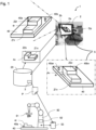
- Programming system 1 illustrated in the figure 1 includes a human-machine communication interface 2 and a programming module 3.
- the human-machine communication interface 2 comprises at least one display surface 2a and selection means.
- the display surface 2a is a screen of a touch tablet equipped with a camera arranged to allow an operator Op to capture the image of the real part 4r / film the real part 4r to obtain a video capture of the part 4r, while observing an image 5 on the screen 2a.
- Image 5 includes the representation of the real part 4r from the video capture and the virtual model 4v superimposed on the representation of the real part 4r.
- the selection means of the communication interface 2 include sensors for detecting support on the display surface 2a of the touch pad.
- programming system 1 could include, in addition or alternatively, other known types of display surface 2a and/or other known types of selection means.
- the machining program P generated by the programming module 3 contains a machining intensity characteristic to be applied, with a real tool 51 carried by the machine tool 50, on the real area to be machined Z1r of the actual part 4r, the machining intensity characteristic to be applied being a function of said machining intensity parameter Px selected by the operator.
- the programming module 3 is arranged to define/determine/calculate the machining intensity characteristic present in the program as a function of said machining intensity parameter Px selected by the operator.
- the machining program generation method is particularly suitable for implementing grinding or sanding or surfacing or lapping type machining of the real part since the quality of the surface condition to be achieved for a given real area is largely dependent on the initial surface condition of the part to be machined and the machining intensities applied respectively zone by zone on the real part.
- the initial surface condition is easily identifiable, zone by zone, by the operator viewing the part to be machined.
- the human-machine communication interface can also be equipped with means of assistance in measuring the surface condition allowing the operator to measure the different initial surface conditions in different areas of the real part in order to assess the machining requirement on these different real areas.
- the representation of the real part on the image allows you to zoom in on the real part to, for example, facilitate the evaluation of the initial surface condition of each real area to be machined.
- the process is all the more suitable for grinding, sanding, surfacing or lapping type machining as the initial surface condition of the actual areas to be machined often varies from one part to another, thus increasing the interest in adapting the machining applied according to the characteristics of the actual part to be machined.
- a part to be ground coming out of a mold may have a satisfactory initial surface condition requiring minimal machining intensity or a particularly degraded initial surface condition requiring a high machining intensity to achieve a machined surface condition conforming to the tolerances predefined in the virtual model.
- the method according to the invention is therefore particularly suitable for grinding or sanding or surfacing or lapping because it allows a significant gain in the allocation of machining intensities adapted to the different areas of the part, a time saving in the generation of the machining program adapted to the actual part, a gain in machining quality and an optimization of the grinding or sanding or surfacing or lapping intensity to be applied.
- the human-machine communication interface comprises a display surface associated with selection means of the screen pressure sensor type.
- These pressure sensors make it possible to detect finger pressure or movements on the screen to select areas of the displayed image in order, for example, to select a virtual area of a virtual model displayed on the screen 2a and to select a machining intensity parameter, for example, via a menu displaying several parameters available for selection for this selected virtual area.
- the human-machine communication interface 2 could include any other means or combination of means for interacting with an operator to enable him to select virtual areas on the image and assign parameters to each of these areas. virtual.
- the selection of a virtual zone can cover the case where one simply selects a predetermined virtual zone of the virtual model or the case where one decides to size using the communication interface the virtual zone that one wishes to select.
- the virtual zones are materialized in the image by graphic representation codes, such as a peripheral border line specific to each virtual zone visible on the image.
- a virtual area selected in the image to assign a desired machining intensity parameter value can be identified there, for example, by highlighting this selected virtual area.
- This graphical representation mode allows you to identify the virtual zone(s) selected in the image which is/are active in order to assign to each given zone the associated desired machining intensity parameter.
- the selection of the machining intensity parameter can be done via a context menu belonging to the selection means and which is displayed in response to the selection of the given virtual zone(s) and which is active for the selected given virtual zone(s) only.
- the context menu can for example show different available values of the intensity parameter in the form of a drop-down menu, check boxes, tabs to select, values to increment or decrement on the menu or any other known means of entering a value.
- the human-machine communication interface 2 can signal on the image a particular graphic representation indicating the current value of the machining intensity parameter selected for each given virtual zone.
- the selected intensity parameter value can be symbolized graphically, for example via a color code, a contrast density code, a pattern/texture density code, alphanumeric characters or any other graphic representation interpretable on the image to distinguish between different machining intensity parameter values.
- the operator has the ability to change the value of the selected parameter on the virtual model depending on the state of the areas of the real part represented in the image.
- the display surface 2a on which the image is displayed is a display surface of an augmented reality interface arranged to superimpose, in the displayed image 5, the predetermined virtual model 4v and the representation of said at least one real part to be machined 4r.
- the virtual model 4v can be displayed by projection on the display surface and the same can be done for the representation of the real part 4r.
- the representation of the virtual part could be an observation of the real part through the transparent surface and the virtual model 4v then being displayed on the display surface 2a, for example by projection.
- the display of the virtual model 4v in image 5 can be done interactively, so that whatever the observation angle of the real part, the model is superimposed on the representation of this real part 4r with the same observation angle and with dimensions adjusted so that the limits of the virtual zones of the virtual model are superimposed on the limits of the corresponding real to machined zones.
- the human-machine communication interface includes a camera 2b.
- the camera 2b and the display surface 2a are preferably fixed on a support to move together with the support, this support being able to be an element of a digital tablet, a smart phone or a mount of a virtual reality mask.
- the camera 2b is shown schematically in dotted lines and is located on a rear face opposite the screen 2a.
- Such a camera could also be a remote device that is mobile relative to the screen 2a.
- the actual part 4r is fixed on a machining fixture 40, a plurality of actual visual cues 40a, 40b being formed on at least one of the actual part 4r and the machining fixture 40.
- markers 40a, 40b may be fixed parts (here studs or spheres) and/or a tattoo and/or an engraving and/or a painting and/or labels such as unique images (a unique image is, for example, a randomly generated image to have a unique character) and/or barcodes, and/or QR codes.
- the virtual model 4v comprises a plurality of virtual visual cues 40av, 40bv, each virtual visual cue corresponding to one of said real visual cues 40a, 40b.
- the superposition in the image of the predetermined virtual model 4v on the representation of the real part to be machined 4r is obtained by recognition in images generated by the camera 2b, by an optical recognition module belonging to the communication interface 2, of at least some of the real visual markers 40a, 40b of the plurality of real visual markers 40a, 40b and by adjustment of orientation and scale of the entire virtual model in the image so that the virtual visual markers 40av, 40bv and the real visual markers 40a, 40b which correspond to each other are respectively superimposed in the displayed image 5 on the display surface 2a.
- the human-machine communication interface 2 here comprises an augmented reality interface, which adapts the dimensions and the observation orientation of the virtual model displayed in the image 5 to superimpose the peripheral limits of the given real zone Z1r on peripheral limits of the given virtual zone Z1v of the virtual model 4r, the real zones of the real part 4r thus being superimposed on the corresponding virtual zones of the virtual model 4v.
- the displayed image 5 shows a representation of the real part 4r and the virtual part 4v with the same size scale and the same observation orientation.
- This representation in augmented reality AR, facilitates the selection and correct assignment of the desired machining intensity parameters respectively associated with the virtual areas visible in image 5.
- the programming module 3 generates the machining program P such that this program P contains a machining intensity characteristic to be applied to the real area to be machined of the real part 4r which is a function of said selected machining intensity parameter.
- the machining intensity characteristic contained in the machining program P is for example chosen from a machining force to be applied with the actual tool 51 against the actual area to be machined, a machining duration to be applied with the actual tool 51 against the actual area to be machined or a combination of said force and said duration.
- the programming system 1 preferably comprises a database 20.
- the human-machine communication interface 2 is then arranged to enter into the database 20, for each at least one given virtual zone Z1v of the virtual model 4v, a pre-recorded value of the machining intensity parameter Px associated with this given virtual zone Z1v of the virtual model 4v.
- the operator is free to select the value proposed in image 5 or, on the contrary, to change the value to a value that is supposedly better suited.
- the database constitutes a history of the selections made for each of the virtual zones of the virtual model.
- such a database 20 can be used to calculate an adapted value of the machining intensity parameter Px associated with each real zone of a part to be machined.
- This calculation of the adapted value of the parameter preferentially takes into account the selections successively made by the operator for the previous machining of one or more 4r parts and for each of the virtual zones of the associated virtual model.
- Such a database 20 is favorable to an improvement in the quality of the successively generated machining programs and to the quality of the successive machining operations.
- the database 20 can thus contain for each given virtual zone of the virtual model 4v, a current value associated with this given virtual zone which is updated according to each selection made by the operator to generate a new machining program P and/or according to observations (made by automated processing or by an intervention of the operator) made on the state of the part to be machined.
- the virtual model 4v has several virtual zones Z1v, Z2v distinct from each other.
- the Op operator notices a defect point to be machined on the real part, he can then delimit a corresponding virtual zone and integrate it into the 4v model.
- the operator can thus select for each virtual zone, the corresponding value proposed / displayed in image 5 or alternatively select another value.
- the machine tool 50 can carry a plurality of real tools 51 each adapted to carry out a machining operation associated with the same given virtual zone of the virtual model.
- These tools can for example be stored in a real tool magazine belonging to the machine tool.
- the pre-recorded machining intensity parameter value associated with said at least one given virtual zone of the virtual model is then also associated with a given real tool 51 of said plurality of real tools such that the pre-recorded machining intensity value is valid for a pair consisting of said at least a given virtual area Z1v of the virtual model 4v and one of the real tools 51 carried by the machine tool 50.
- the machine tool 50 can for example carry several cutters or abrasive heads or several grinding wheels 51 each having its own grain and its own level of wear.
- the operator Op then has the possibility of choosing which of these real tools from the plurality of tools must be selected to carry out the particular machining of the real area of the part 4r.
- the machining intensity parameter proposed for selection to generate the machining program has a value defined as a function on the one hand of the given virtual zone of the virtual model and on the other hand of the real tool selected to carry out the machining.
- the value of the machining intensity parameter proposed for selection may change depending on the nature of the actual tool chosen and depending on the level wear of this real tool.
- the wear of the real tool is indirectly taken into account in the evolution of the choice of the machining intensity parameter to be applied.
- the machining intensity characteristic in the machining program is then increased according to the value of the new machining intensity parameter selected by the operator and the machining carried out by the machine tool will have an increased intensity on the corresponding real area of the part (in increased force and/or in increased machining time).
- this increased value can then be proposed for selection to generate a new machining program to machine a new real part.
- the operator will be able to select a real tool carried by the machine to carry out this grinding operation and the human-machine communication interface will then propose to the operator a pre-recorded value of the machining intensity parameter associated with the corresponding virtual area of the virtual model and with the grinding tool selected by the operator.
- the data contained in the database 20 may be sought to use the data contained in the database 20 to calculate an adapted value of the machining intensity parameter that the operator may or may not choose as the machining intensity parameter Px selected for a given area of the part to be machined.
- This history groups together selections made for 4r parts from the same series of parts and possibly from another series of parts previously machined with the 50 machine tool.
- the programming system allows an adaptation of the machining intensity parameter Px proposed for the generation of a program P according to past selections made to generate machining programs P of parts 4r of the same series of parts or possibly other series.
- Each calculated value is proposed to the operator for machining a given real area of a 4r part to be machined.
- the method according to the invention allows a continuous improvement of the quality of the machining, including during the machining of a series of parts.
- the ability to improve programming quality is increased with the size of the part series.
- the calculation of the adapted values of machining intensity parameters based on the history is for example carried out by an artificial neural network implemented by a calculation module belonging to the programming system 1.
- This neural network is optionally optimized by probabilistic learning methods based on the history recorded in the database 20.
- the machining system 1 thus includes a learning capacity based on past machining operations and successive selections made by the operator following the method of the invention.
- the system programming device 1 can be arranged so that the calculation of each adapted value of machining intensity parameter Px associated with a given virtual zone Z1v of the virtual model is carried out on the basis of data from an image capture of the corresponding real zone of the workpiece.
- each adapted value of machining intensity parameter associated with an actual area to be machined of a real part can be calculated based on an analysis of one or more image captures of the part P to be machined.
- the programming system 1 can be arranged so that the calculation of each adapted value of machining intensity parameter Px associated with a given virtual zone Z1v of the virtual model 4v is carried out according to data from image captures of real zones of parts previously machined by the machine tool 50 which correspond to this same given virtual zone Z1v.
- the image captures and/or the data from these image captures of given real areas of real parts which correspond to the same given virtual area of the virtual model 4v are each stored in the database 20 with the corresponding value of the machining intensity parameter Px which has been selected for the given real area.
- Comparing data from image captures of a workpiece with data from image captures of real workpieces for which the respective machining intensity values have been selected helps to improve the accuracy of calculating the appropriate value for a real area to be machined.
- the adapted value is calculated by taking into account the characteristics of the actual area to be machined and the history of previously made selections.
- the selection operation is thus facilitated since the proposed value is increasingly accurate with the progressive increase in the volume of data contained in the database 20.
- the programming system 1 finds that the actual area to be machined of the workpiece has surface features observable on the image capture that are comparable to surface features previously observed on other image captures of other actual parts, then the system 1 will calculate and propose a calculated value of parameter Px taking into account the Px parameters selected for these other parts Px having these comparable surface features.
- the database 20 is sufficiently enriched so that the value propositions adapted by the programming system 1 are systematically relevant/correct and are systematically selected by the operator.
- the operator can then choose to activate, via the human-machine communication interface 2, an automatic selection function of the machining parameter Px such that the machining intensity parameter selected for the generation of the machining program P is equal to the value adapted from the machining intensity parameter calculated by the programming system.
- the human-machine communication interface 2 is functionally connected to a measuring instrument 52 equipping the machine tool 50.
- the measuring instrumentation 52 is then arranged to measure over time, during the machining of the real part 4r, a variation in the forces applied by the real tool 51 on the real zone Z1r of the real part 4r.
- the method may then include verifying that the forces applied to the real zone Z1r of the real part 4r during the machining of the real part are indeed equal, to within a predefined tolerance value, to said machining intensity characteristic to be applied.
- the communication interface 2 is arranged to record in the database 20, data representative of the force variation measurements delivered by the measuring instrumentation 52.
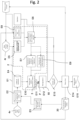
- FIG. 2 illustrates an example of implementation of the method according to the invention in the case where it is desired to machine several real parts 4r belonging to a series of n real parts of the same type p which corresponds to the virtual model 4v common to the parts of type p.
- Each given real 4r coin of type p is individually identified by a rank number n which is specific to it and which is unique in the series.
- the virtual model 4v is identified by the term “Model Num Piéce p”.
- a first preparatory part can be implemented as illustrated in this figure 2 .
- This preparatory part consists of proposing for the virtual 4v model of type p part, theoretical machining trajectories each defined using a given “manufacturing entity”.
- a manufacturing entity is composed of a virtual geometry of a part of a workpiece to be machined, i.e. a virtual area to be machined, a virtual tool to perform this machining (here a grinding tool or a sanding tool) and a set of cutting/abrasion conditions associated with this given tool (feed rate, cutting speed, force to be applied).
- a trajectory can be defined for each virtual area of the model, the trajectory being able to evolve according to modifications of the size or the shape of the virtual area.
- the digital model makes it possible to represent the machining environment to ensure the feasibility of the different trajectories.
- These manufacturing entities and trajectories are for example created by an “entity creation process” E2 which can be automated and/or supervised by the operator by means of the human-machine communication interface 2.
- this step of “entity creation process” E2 is optimized using a learning tool called “learning of relevant entities” E3.
- This “learning of relevant entities” process E3 can for example observe the choices made by the operator when creating the manufacturing entities and can store them in the database 20, with the parameters of these manufacturing entities E2.
- step E4 each of these manufacturing entities defining at least one given virtual zone of the predetermined virtual model 4v and a movement trajectory of a given tool which is associated with this at least one virtual zone.
- the majority of the virtual zones of the predetermined virtual model 4v are then determined with a theoretical tool movement trajectory specific to each of these virtual zones.
- the machining program P is intended to machine, in this case grind, the real part 4r of rank n of the series of parts of type p.
- Step E1 consists of verifying that the part 4r of rank n (denoted “physical part p rank n”) is indeed of the same type p as the virtual model 4v.
- a step E5 consists of displaying the virtual model 4v on the display surface 2b where the real part 4r is also represented.
- the virtual model 4v and the representation of the real part 4r are preferentially superimposed in the image (see for example the representation framed in dashed lines on the figure 1 ).
- the image is displayed in augmented reality so that the displayed model follows the movements in the image of the real part 4r represented to give the illusion to the user that the virtual model forms only one object with the representation of the real part.
- This step E5 is named “AR System” for displaying the image on the Augmented Reality system.
- This step E6 of identifying the real areas is noted “Identification of the areas to be ground + entities by area”.
- step E6 the operator selects, one after the other, the virtual zones of the virtual model which correspond to real zones to be machined and selects for each selected virtual zone an associated desired machining intensity parameter Px.
- This step E6 of selecting each of the virtual zones with the associated displayed Px parameters is made easier here by displaying a proposal for intensity parameter Px per virtual zone visible in the image.
- step E8 The proposed values of parameter Px are generated here in step E8 named “Pre-proposal process”.
- a suitable proposed parameter value may be calculated by the programming system based on data from one or more image captures of the workpiece.
- each intensity parameter Px selected for a selected virtual area is translated/converted into a machining intensity characteristic to be applied to the corresponding real area of part n.
- the intensity characteristic is a machining force to be applied with the actual tool expressed in Newton and/or in force application time and/or in tool movement speed and/or in tool rotation or oscillation speed.
- This step E7 of translating each selected intensity parameter Px into an intensity characteristic is called “translation into Newton of the operator’s “intensity” feeling”.
- Virtual areas can be predefined in the virtual model and/or be defined dimensioned in the virtual model by the operator using the selection means.
- the operator notices a defect located at a point in the representation of the real part in the image, he can then directly select on the displayed virtual model, a new virtual zone containing this defect.
- step E6 The selection of virtual areas and the possible sizing/resizing of virtual areas are carried out in step E6.
- each virtual area defined/selected in the image is integrated into the virtual model in the form of an entity possibly associated with a tool suitable for machining the corresponding real area on the real part.
- This step E9 of integrating the possibly resized virtual zones is called “translation of the identified zones into necessary entities”.
- step E10 This integration into a data set is carried out in step E10 called “Selection of entities + business parameters”.
- the programming module 3 can then receive this data set and generate a machining program P specifically adapted to the real part 4r of rank n and type p.
- step E11 The generation of the program P is carried out in step E11.
- the program is then sent to a control unit 53 of the machine tool 50 to be executed there in order to grind/sand the actual part n.
- step E12 This machining is carried out in step E12 called “grinding part n”.
- This control operation can be carried out directly on the part with control tools and/or using the human-machine communication interface 2.
- step E13 control by the operator.
- part n is considered finished (step E14 named "part n finished”) and a machining report for part n can be generated at step E15 named "part n edited report”.
- the database 20 is then enriched with the selection information made by the operator and the information indicating that this information was relevant and led to a satisfactory machined part.
- the operator can then restart the operations for a new part n+1 of the series of parts to be ground of type p.
- grinding series size This series presents a number of workpieces called "grinding series size”.
- step E13 the operator considers that the machined part n does not conform to his expectations (NOK)
Landscapes
- Engineering & Computer Science (AREA)
- Physics & Mathematics (AREA)
- Robotics (AREA)
- Mechanical Engineering (AREA)
- Geometry (AREA)
- Human Computer Interaction (AREA)
- Manufacturing & Machinery (AREA)
- General Physics & Mathematics (AREA)
- Automation & Control Theory (AREA)
- Numerical Control (AREA)
Applications Claiming Priority (1)
| Application Number | Priority Date | Filing Date | Title |
|---|---|---|---|
| FR2305032A FR3149099A1 (fr) | 2023-05-22 | 2023-05-22 | Procédé de génération d’un programme d’usinage à l’aide d’un système de programmation. |
Publications (2)
| Publication Number | Publication Date |
|---|---|
| EP4478141A2 true EP4478141A2 (de) | 2024-12-18 |
| EP4478141A3 EP4478141A3 (de) | 2025-02-26 |
Family
ID=87748265
Family Applications (1)
| Application Number | Title | Priority Date | Filing Date |
|---|---|---|---|
| EP24176204.6A Pending EP4478141A3 (de) | 2023-05-22 | 2024-05-16 | Verfahren zur erzeugung eines bearbeitungsprogramms mit einem programmiersystem |
Country Status (2)
| Country | Link |
|---|---|
| EP (1) | EP4478141A3 (de) |
| FR (1) | FR3149099A1 (de) |
-
2023
- 2023-05-22 FR FR2305032A patent/FR3149099A1/fr active Pending
-
2024
- 2024-05-16 EP EP24176204.6A patent/EP4478141A3/de active Pending
Also Published As
| Publication number | Publication date |
|---|---|
| EP4478141A3 (de) | 2025-02-26 |
| FR3149099A1 (fr) | 2024-11-29 |
Similar Documents
| Publication | Publication Date | Title |
|---|---|---|
| EP3066521B1 (de) | Verfahren zur bestimmung mindestens eines optischen designparameters für eine progressive kontaktlinse | |
| EP1722924B1 (de) | Vorrichtung zum zentrieren/festklemmen eines brillenglases, zugehörige verfahren zur manuellen zentrierung und verfahren zur automatischen erfassung | |
| EP2008149B1 (de) | Verfahren zum detektieren eines optischen koordinatensystems für eine optische linse | |
| EP4127812B1 (de) | Lupe für einen elektronischen uhrmacher, lupe für einen elektronischen uhrmacher und verfahren zur durchführung einer prüfung eines uhrproduktes, insbesondere eines uhrmechanismus | |
| EP2242621A2 (de) | Verfahren zum training eines roboters oder einer ähnlichen vorrichtung sowie vorrichtung zur anwendung dieses verfahrens | |
| EP2082374A1 (de) | Verfahren und hilfe zur modellierung von 3d-objekten | |
| EP3608881A1 (de) | System und verfahren zur automatischen erzeugung wertvoller schneidpläne für einen rohen edelstein | |
| EP1671192B1 (de) | Verfahren zum kalibrieren einer brillenlinsen-durchdringungsmaschine, einrichtung zur implementierung eines solchen verfahrens und eine solche einrichtung umfassende brillenlinsen-bearbeitungs-vorrichtung | |
| EP2150375B1 (de) | Konturfräsverfahren für brillengläser mittels ablesen und aktualisierung eines datenbankregisters für linsen und/oder fassungen | |
| EP1913556A2 (de) | Verfahren und vorrichtung zur bestimmung der anordnung eines videoerfassungsmittels in der erfassungsmarkierung mindestens eines dreidimensionalen objekts, mit dem mindestens ein reales objekt modelliert wird | |
| EP4117867A1 (de) | Verfahren zur automatischen durchführung einer operation an einem objekt mit einem von einem mehrgelenkigen system getragenen werkzeug | |
| EP3074178B1 (de) | Verfahren zur bekantung eines brillenglases | |
| EP4478141A2 (de) | Verfahren zur erzeugung eines bearbeitungsprogramms mit einem programmiersystem | |
| EP3329208A1 (de) | Verfahren zur überprüfung der übereinstimmung mit einem vorgegebenen benutzungskriterium eines brillengestells und zugehörige vorrichtung | |
| WO2006106196A1 (fr) | Methode de centrage d'une lentille ophtalmique sur une monture sans cercles | |
| FR3020891A1 (fr) | Procede de simulation d'un montage et/ou d'une utilisation d'un ensemble fonctionnel de plate-forme, et systeme associe | |
| EP4116762B1 (de) | Vorrichtung zur unterstützung der herstellung eines endgültigen korrekturlinsenglases und entsprechendes verfahren | |
| WO2020058643A1 (fr) | Procede, module et systeme de projection sur une piece d'une image calculee a partir d'une maquette numerique | |
| WO2025224355A1 (fr) | Procédé de requête de production de dessin et procédé de production de dessin, terminal de communication et programme les mettant en œuvre | |
| WO2025125337A1 (fr) | Procédé et dispositif de modélisation d'un objet réel | |
| WO2022079011A1 (fr) | Procédé et système d'assistance au soin du corps | |
| FR2766932A1 (fr) | Centrale de mesure en optique |
Legal Events
| Date | Code | Title | Description |
|---|---|---|---|
| PUAI | Public reference made under article 153(3) epc to a published international application that has entered the european phase |
Free format text: ORIGINAL CODE: 0009012 |
|
| STAA | Information on the status of an ep patent application or granted ep patent |
Free format text: STATUS: THE APPLICATION HAS BEEN PUBLISHED |
|
| AK | Designated contracting states |
Kind code of ref document: A2 Designated state(s): AL AT BE BG CH CY CZ DE DK EE ES FI FR GB GR HR HU IE IS IT LI LT LU LV MC ME MK MT NL NO PL PT RO RS SE SI SK SM TR |
|
| PUAL | Search report despatched |
Free format text: ORIGINAL CODE: 0009013 |
|
| AK | Designated contracting states |
Kind code of ref document: A3 Designated state(s): AL AT BE BG CH CY CZ DE DK EE ES FI FR GB GR HR HU IE IS IT LI LT LU LV MC ME MK MT NL NO PL PT RO RS SE SI SK SM TR |
|
| RIC1 | Information provided on ipc code assigned before grant |
Ipc: B25J 9/16 20060101ALI20250120BHEP Ipc: G05B 19/4093 20060101AFI20250120BHEP |
|
| STAA | Information on the status of an ep patent application or granted ep patent |
Free format text: STATUS: REQUEST FOR EXAMINATION WAS MADE |
|
| 17P | Request for examination filed |
Effective date: 20250613 |
|
| 111L | Licence recorded |
Designated state(s): AL AT BE BG CH CY CZ DE DK EE ES FI FR GB GR HR HU IE IS IT LT LU LV MC ME MK MT NL NO PL PT RO RS SE SI SK SM TR Free format text: EXCLUSIVE LICENSE Name of requester: POLYFLYX, FR Effective date: 20250916 |
|
| GRAP | Despatch of communication of intention to grant a patent |
Free format text: ORIGINAL CODE: EPIDOSNIGR1 |
|
| STAA | Information on the status of an ep patent application or granted ep patent |
Free format text: STATUS: GRANT OF PATENT IS INTENDED |
|
| INTG | Intention to grant announced |
Effective date: 20260107 |
|
| GRAS | Grant fee paid |
Free format text: ORIGINAL CODE: EPIDOSNIGR3 |