EP4477945A1 - Holding device, mounting frame and recessed light - Google Patents
Holding device, mounting frame and recessed light Download PDFInfo
- Publication number
- EP4477945A1 EP4477945A1 EP24179651.5A EP24179651A EP4477945A1 EP 4477945 A1 EP4477945 A1 EP 4477945A1 EP 24179651 A EP24179651 A EP 24179651A EP 4477945 A1 EP4477945 A1 EP 4477945A1
- Authority
- EP
- European Patent Office
- Prior art keywords
- rail
- guide
- carriage
- longitudinal
- counter
- Prior art date
- Legal status (The legal status is an assumption and is not a legal conclusion. Google has not performed a legal analysis and makes no representation as to the accuracy of the status listed.)
- Pending
Links
Images


Classifications
-
- F—MECHANICAL ENGINEERING; LIGHTING; HEATING; WEAPONS; BLASTING
- F21—LIGHTING
- F21S—NON-PORTABLE LIGHTING DEVICES; SYSTEMS THEREOF; VEHICLE LIGHTING DEVICES SPECIALLY ADAPTED FOR VEHICLE EXTERIORS
- F21S8/00—Lighting devices intended for fixed installation
- F21S8/02—Lighting devices intended for fixed installation of recess-mounted type, e.g. downlighters
- F21S8/026—Lighting devices intended for fixed installation of recess-mounted type, e.g. downlighters intended to be recessed in a ceiling or like overhead structure, e.g. suspended ceiling
-
- F—MECHANICAL ENGINEERING; LIGHTING; HEATING; WEAPONS; BLASTING
- F21—LIGHTING
- F21V—FUNCTIONAL FEATURES OR DETAILS OF LIGHTING DEVICES OR SYSTEMS THEREOF; STRUCTURAL COMBINATIONS OF LIGHTING DEVICES WITH OTHER ARTICLES, NOT OTHERWISE PROVIDED FOR
- F21V21/00—Supporting, suspending, or attaching arrangements for lighting devices; Hand grips
- F21V21/02—Wall, ceiling, or floor bases; Fixing pendants or arms to the bases
- F21V21/04—Recessed bases
- F21V21/041—Mounting arrangements specially adapted for false ceiling panels or partition walls made of plates
- F21V21/042—Mounting arrangements specially adapted for false ceiling panels or partition walls made of plates using clamping means, e.g. for clamping with panel or wall
- F21V21/044—Mounting arrangements specially adapted for false ceiling panels or partition walls made of plates using clamping means, e.g. for clamping with panel or wall with elastically deformable elements, e.g. spring tongues
- F21V21/045—Mounting arrangements specially adapted for false ceiling panels or partition walls made of plates using clamping means, e.g. for clamping with panel or wall with elastically deformable elements, e.g. spring tongues being tensioned by translation of parts, e.g. by pushing or pulling
-
- F—MECHANICAL ENGINEERING; LIGHTING; HEATING; WEAPONS; BLASTING
- F21—LIGHTING
- F21V—FUNCTIONAL FEATURES OR DETAILS OF LIGHTING DEVICES OR SYSTEMS THEREOF; STRUCTURAL COMBINATIONS OF LIGHTING DEVICES WITH OTHER ARTICLES, NOT OTHERWISE PROVIDED FOR
- F21V29/00—Protecting lighting devices from thermal damage; Cooling or heating arrangements specially adapted for lighting devices or systems
- F21V29/50—Cooling arrangements
- F21V29/70—Cooling arrangements characterised by passive heat-dissipating elements, e.g. heat-sinks
- F21V29/74—Cooling arrangements characterised by passive heat-dissipating elements, e.g. heat-sinks with fins or blades
- F21V29/77—Cooling arrangements characterised by passive heat-dissipating elements, e.g. heat-sinks with fins or blades with essentially identical diverging planar fins or blades, e.g. with fan-like or star-like cross-section
- F21V29/773—Cooling arrangements characterised by passive heat-dissipating elements, e.g. heat-sinks with fins or blades with essentially identical diverging planar fins or blades, e.g. with fan-like or star-like cross-section the planes containing the fins or blades having the direction of the light emitting axis
-
- F—MECHANICAL ENGINEERING; LIGHTING; HEATING; WEAPONS; BLASTING
- F21—LIGHTING
- F21Y—INDEXING SCHEME ASSOCIATED WITH SUBCLASSES F21K, F21L, F21S and F21V, RELATING TO THE FORM OR THE KIND OF THE LIGHT SOURCES OR OF THE COLOUR OF THE LIGHT EMITTED
- F21Y2115/00—Light-generating elements of semiconductor light sources
- F21Y2115/10—Light-emitting diodes [LED]
Definitions
- the present invention relates to a holding device for a mounting frame of a recessed luminaire for mounting in a mounting opening of a ceiling or wall, according to the preamble of claim 1.
- the invention also relates to a mounting frame which is equipped with several such holding devices, as well as to a recessed luminaire which is equipped with such a mounting frame.
- a generic holding device is known, for example, from EP 2 893 248 B1 known and has a straight rail that has a longitudinal direction, a transverse direction and a height direction, as well as a carriage that is attached to the rail so that it can be adjusted in the longitudinal direction.
- the rail has a guide running in the longitudinal direction on each of two long sides facing away from each other in the transverse direction, while the carriage is equipped with two counter-guides that are complementary to the guides and are coupled to the guides for the guided longitudinal displacement of the carriage in the longitudinal direction along the rail.
- the carriage can be adjusted between a holding position, an intermediate position and an assembly position. In the holding position, the carriage is located in a first longitudinal region of the rail.
- the carriage In the intermediate position, the carriage is located in a second longitudinal region of the rail facing away from the first longitudinal region. In the assembly position, the carriage is in the second longitudinal region and is pivoted about a pivot axis relative to the rail.
- the pivot axis extends parallel to the transverse direction and is defined by two cylindrical pins that protrude from the carriage and form components of the counter-guides. The pins engage in complementary longitudinal grooves, which form part of the guides and are attached to the rail are formed.
- a plurality of such holding devices can be provided on a mounting frame which can be inserted into a mounting opening when the slides are in the mounting position and which is held on an opening edge surrounding the mounting opening when the slides are transferred to their holding position.
- a recessed luminaire equipped with such a mounting frame can be attached to the wall or ceiling using this mounting frame.
- the present invention addresses the problem of providing an improved or at least a different embodiment for such a holding device or for a mounting frame equipped therewith or for a recessed luminaire equipped therewith, which enables simple and reliable installation of the recessed luminaire.
- the invention is based on the general idea of coordinating or configuring the rail and the slide in such a way that the pivot axis around which the slide can be pivoted relative to the rail between the intermediate position and the mounting position extends parallel to the longitudinal direction.
- This measure enables the slide to be manually grasped at the side of the rail and pivoted around the pivot axis relative to the rail.
- a “configuration” is synonymous with a “design”, so that the phrase “configured so that” is synonymous with the phrase “designed so that”.
- the pivotability of the carriage relative to the rail about the pivot axis running parallel to the longitudinal direction is achieved in the holding device presented here by the fact that one or first guide extends from the first longitudinal area to the second longitudinal area, while the other or second guide extends only in the first longitudinal area.
- the one or first The counter guide and the first guide are now configured in such a way that the carriage can be pivoted about the pivot axis relative to the rail in the intermediate position.
- the pivot axis running parallel to the longitudinal direction is defined by the first guide and the first counter guide.
- the first guide and the first counter guide form a pivot bearing for the carriage on the rail.
- the other or second counter guide is coupled to the second guide in the holding position and decoupled from the second guide in the intermediate position.
- the carriage By decoupling the second counter guide from the second guide in the intermediate position, the carriage can be pivoted about the pivot axis relative to the rail using the first guide and the first counter guide and thus adjusted between the intermediate position and the assembly position. If the carriage is in the intermediate position, it can be moved longitudinally along the rail, with the second guide and the second counter guide then being coupled to improve the longitudinal guidance of this longitudinal adjustment. This allows the carriage to be moved longitudinally between the holding position and the intermediate position.
- the first guide has a first guide rod which is connected to the rail on the respective long side of the rail via a web and extends in a straight line in the longitudinal direction.
- the web is interrupted in the second longitudinal region such that a gap is formed in the second longitudinal region between the first guide rod and the rail.
- the first counter-guide is configured such that it encompasses the first guide rod by more than 180° and by less than 360° such that the first counter-guide has a gap which extends continuously in the longitudinal direction. This gap is dimensioned such that the web can be moved into the gap when the carriage is moved longitudinally in the longitudinal direction. penetrates and penetrates the gap transversely to the longitudinal direction.
- the first counter-guide is therefore designed as a slotted sleeve.
- the gap in the sleeve forms a longitudinal slot in which the web can move longitudinally to enable the carriage to be moved longitudinally along the rail. Since the first counter-guide engages around the first guide rod, the carriage and the rail can also be pivoted around the pivot axis. The pivot axis then runs coaxially to the guide rod.
- the gap in the web provided in the second longitudinal region means that the first counter-guide can move into the gap when pivoting, thereby enabling the carriage and rail to pivot. Since the first counter-guide engages around the first guide rod by more than 180°, preferably by at least 270°, the first counter-guide is held captively on the first guide rod transversely to the longitudinal direction.
- the second guide can have a second guide rod, which is connected to the rail on the respective long side of the rail via a web and extends in a straight line in the longitudinal direction.
- the second guide rod In contrast to the first guide rod, the second guide rod only extends in the first longitudinal area.
- the second counter-guide surrounds the second guide rod by more than 180° and less than 360°, so that the second counter-guide also has a gap that extends continuously in the longitudinal direction and is dimensioned such that the web penetrates into the gap when the carriage is moved longitudinally in the longitudinal direction and penetrates the gap transversely to the longitudinal direction.
- the second guide and the second counter-guide are thus constructed almost identically in the first longitudinal section to the first guide and the first counter-guide. Since the second guide rod only extends in the first longitudinal area, the decoupling between the second counter-guide and the second inevitably occurs in the second longitudinal area. Guide as soon as the second counter guide is released from the second guide rod during displacement in the longitudinal direction.
- the respective gap is located in the circumferential direction of the respective counter-guide, which runs around the longitudinal direction, and represents a longitudinal slot of the sleeve-shaped counter-guide.
- the rail can have an opening penetrating the rail and a slot penetrating the rail in the transverse direction between the guides.
- the opening is formed in the second longitudinal region, while the slot extends in the longitudinal direction from the first longitudinal region into the opening.
- the slot opens into the opening.
- the opening is larger in the transverse direction than the slot.
- the opening, the slot, the securing element and the connecting web are now coordinated with one another in such a way that when the carriage is pivoted about the pivot axis between the intermediate position and the assembly position, the securing element can be adjusted through the opening and that when the carriage is moved longitudinally between the intermediate position and the holding position, the connecting web can be adjusted longitudinally in the slot and in doing so penetrates the slot and positions the securing element on a side of the rail facing away from the carriage.
- the locking element guided in the slot creates an additional positive connection between the slide and the rail and improves the support between the slide and the rail.
- the positioning of the locking element here is equivalent to a positive hold transverse to the longitudinal direction between the carriage and the rail by means of the shear element and the connecting web.
- the gap of the first counter-guide can be positioned such that the first counter-guide can be plugged onto and removed from the first guide rod in the longitudinal direction when the securing element is moved out of the opening by pivoting the carriage about the pivot axis, so that the carriage can be mounted on and removed from the rail.
- a configuration is advantageous in which the first counter-guide has a constriction at a longitudinal end facing away from the first longitudinal region of the rail in the gap with respect to a circumferential direction with which the first counter-guide engages around the first guide rod, for example in the form of a nose protruding in the circumferential direction of the counter-guide, this constriction being smaller in this circumferential direction than a web section that delimits the gap between the rail and the first guide rod on a side facing away from the first longitudinal region.
- a web section that delimits the gap on a side facing away from the first longitudinal region is larger in size than the gap of the first counter-guide with respect to a circumferential direction with which the first counter-guide engages around the first guide rod.
- a locking contour can be formed on one of the rail and slide, which has a plurality of locking steps adjacent in the longitudinal direction.
- a counter-locking contour complementary to the locking steps can be formed, which has at least one locking lug that interacts with the locking steps to maintain the relative position between the slide and the rail with respect to the longitudinal direction.
- the locking contour with a plurality of locking steps adjacent in the longitudinal direction predetermines a plurality of positions in the longitudinal direction between the rail and slide in which the slide is held on the rail.
- a preferred development is one in which the locking contour is formed on the rail, with the locking steps being formed on a side of the rail facing the carriage in the holding position on both sides of the slot.
- the counter-locking contour is then formed on the carriage, with at least one such locking lug being formed on a side of the carriage facing the securing element.
- the locking contour and the counter-locking contour work together to position the carriage relative to the rail by means of a positive connection running transversely to the longitudinal direction.
- the securing element ensures a secure and in particular pre-tensioned engagement between the locking steps and the locking lugs, whereby the respective locking position is secured.
- the carriage may have a pressing area which, in the holding position, projects away from the rail in the vertical direction.
- a pressing area which, in the holding position, projects away from the rail in the vertical direction.
- the pressing area is connected to the slide via a spring area, which can in particular be designed to be elastic, is particularly advantageous.
- the mounting frame can be fixed to the respective opening edge by clamping the opening edge between the pressing areas of the holding devices and the mounting frame with respect to the longitudinal direction. At the same time, this achieves clean assembly with the mounting frame resting all around on the opening edge.
- a mounting frame according to the invention which is intended for mounting a recessed light in a mounting opening in a ceiling or wall surrounded by an opening edge, has a frame body which has a flange for contact with an outside of the opening edge facing away from the mounting opening, as well as several holding devices of the type described above, which are arranged on the frame body in a circumferential direction.
- the flange runs along the frame body in a circumferential direction around a longitudinal center axis of the frame body.
- the flange preferably runs closed around the frame body in the circumferential direction.
- the respective rail can now be firmly connected to the frame body with the longitudinal direction aligned parallel to the longitudinal center axis. This allows the slides to be adjusted parallel to one another along the rails.
- the mounting frame can be inserted into the mounting opening when the slides assume their mounting position.
- the mounting frame then has transverse to the longitudinal center axis.
- the mounting frame correctly inserted into the mounting opening, rests with its flange on the outside of the opening edge and is fixed to the opening edge when the slides assume their holding position and are supported on an inside of the opening edge facing the mounting opening.
- the cross-section of the mounting frame in the area of the holding devices is in any case larger than the cross-section of the mounting opening and preferably also larger than the cross-section in the area of the flange. This allows the mounting frame to be supported positively on the opening edge using the slides.
- the opening edge is then clamped parallel to the longitudinal center axis between the flange and the slides.
- the respective slide can be designed separately from the frame body, i.e. form a separate component in this respect, and can be attached to the frame body by means of a clip or snap-in connection.
- This allows the frame body and slide to be easily manufactured separately, for example as cast parts and/or from plastic.
- an integrated design is also conceivable in which the slides are integrally formed on the frame body.
- the frame body can be closed in the circumferential direction.
- the frame body can have, for example, a polygonal or rectangular or round or circular cross-section.
- the frame body is adapted to the respective mounting opening in terms of its cross-section or vice versa.
- a recessed luminaire according to the invention is intended for installation in a mounting opening in a ceiling or wall surrounded by an opening edge.
- the recessed light is equipped with a mounting frame of the type described above. It also has a lamp carrier that is directly or indirectly connected to the mounting frame. At least one lamp can be arranged on this lamp carrier, which can in particular have at least one light-emitting diode.
- the recessed light can be particularly easily installed in a mounting opening.
- a detachable connection is provided between the mounting frame and the lamp carrier, which is designed in such a way that the mounting frame can first be mounted in the mounting opening without the lamp carrier or fastened to the edge of the opening. The lamp carrier can then be fastened to the mounting frame already fixed to the edge of the opening.
- a detachable fastening can be realized, for example, by a latch or by a bayonet lock or by a screw thread.
- the recessed light can have a reflector that connects the mounting frame to the lamp carrier.
- the aforementioned detachable fastening between the lamp carrier and the mounting frame can now be formed between the reflector and the mounting frame, so that the reflector can be detachably fastened to the mounting frame.
- the lamp carrier can in turn be permanently or detachably fastened to the reflector.
- the recessed luminaire can have a heat sink, in particular with cooling fins, which is connected to the lamp carrier in a heat-transferring manner.
- a recessed luminaire 1 comprises a mounting frame 2, a lamp carrier 3 and at least one Figure 5 indicated illuminant 4, which is arranged on the illuminant carrier 3.
- the illuminant 4 can have one or more light-emitting diodes as well as power electronics.
- the recessed luminaire 1 is also equipped with a reflector 5, which connects the mounting frame 2 to the illuminant carrier 3.
- the recessed luminaire 1 has a heat sink 6, which is equipped with several cooling fins 7 and which is held on the illuminant carrier 3 or on the reflector 5 and which is connected to the illuminant 4 in a heat-transferring manner.
- the recessed luminaire 1 is designed for installation in a Figure 5 recognizable mounting opening 8 is provided, which is formed in a ceiling 9 or wall 10 and is surrounded by an opening edge 11.
- the mounting frame 2 serves to secure the recessed light 1 to this opening edge 11.
- the mounting frame 2 is equipped with several holding devices 12, which are arranged on the mounting frame 2 distributed in a circumferential direction U of the mounting frame 2.
- the circumferential direction U of the mounting frame 2 runs around a longitudinal center axis L of the recessed light 1 or the mounting frame 2.
- the respective holding device 12 has a straight rail 13 which is configured to be straight and flat and defines a longitudinal direction X, a transverse direction Y and a height direction Z which are perpendicular to one another.
- the longitudinal directions X of the holding devices 12 extend according to the Figures 1 and 5 parallel to Longitudinal center axis L of the mounting frame 2.
- the respective holding device 12 is also equipped with a carriage 14 which is arranged on the respective rail 13 so as to be adjustable in the longitudinal direction X.
- the respective rail 13 has a rail length extending in the longitudinal direction X, a rail width extending in the transverse direction Y and a rail thickness extending in the vertical direction Z. In the case of the elongated and flat rails 13, the rail thickness is smaller than the rail width, which in turn is smaller than the rail length.
- the respective rail 13 has a guide 15 on each of two longitudinal sides facing away from each other in the transverse direction Y, which guide runs in the longitudinal direction X.
- the respective carriage 14 has two counter-guides 16, which are designed to be complementary to the guides 15.
- the counter-guides 16 are coupled to the guides 15 and interact with the guides 15 to enable a guided longitudinal displacement of the carriage 14 in the longitudinal direction X along the rail 13.
- the two guides 15 form a first guide 15a and a second guide 15b.
- the two counter-guides 16 form a first counter-guide 16a, which interacts with the first guide 15a, and a second counter-guide 16b, which interacts with the second guide 15b.
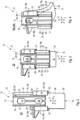
- the carriage 14 is between a Figure 2 shown holding position HS, one in Figure 3 shown intermediate position ZS and one in Figure 4 shown mounting position MS relative to the respective rail 13.
- Figure 1 In the three holding devices 12 shown, the slides 14 are shown in three different positions.
- Figure 1 The carriage 14 is adjusted to the mounting position MS in the holding device 12 facing the viewer.
- Figure 1 holding device on the left 12 the slide 14 is adjusted to the holding position HS.
- the slide 14 is adjusted to the intermediate position ZS by means of the holding device 12 arranged on the right.
- the slide 14 is in the holding position HS.
- Figure 5 The carriage 14 is in the mounting position MS in the holding device 12 facing away from the viewer and partially covered by the lamp carrier 3 or the heat sink 6.
- Figure 4 does not show the carriage 14 fully pivoted into the assembly position MS, but a pivot position MS', which results from the transition from the intermediate position ZS into the assembly position MS and which can be used, for example, to mount the carriage 14 on the rail 13, which is explained in more detail below.
- the carriage 14 fully pivoted into the assembly position MS is in Figure 1 at the front holding device 12 facing the viewer and in Figure 5 visible at the rear holding device 12 facing away from the viewer.
- the carriage 14 In the holding position HS, the carriage 14 is located in a first longitudinal region 17 of the rail 13, which faces the mounting frame 2 when the holding device 12 is attached to the mounting frame 2. In the intermediate position ZS, however, the carriage 14 is located in a second longitudinal region 18 of the respective rail 13, which faces away from the first longitudinal region 17. This second longitudinal region 18 faces away from the holding frame 2 when the holding device 12 is attached to the mounting frame 2. In the mounting position MS, the respective carriage 14 is located in the second longitudinal region 18 and is pivoted about a pivot axis S relative to the rail 13. The rail 13 and carriage 14 are configured such that the pivot axis S extends parallel to the longitudinal direction X.
- the holding devices 12 are configured such that the one or first guide 15a extends from the first longitudinal region 17 to the second longitudinal region 18, while the other or second guide 15b extends only in the first longitudinal region 17, i.e. is significantly shorter than the first guide 15a with respect to the longitudinal direction X.
- the first guide 15a extends over the entire length of the rail, while the second guide 15b extends only over approximately half of the length of the rail.
- the one or first counter-guide 16a and the first guide 15a are configured such that the carriage 14 can be pivoted about the pivot axis S relative to the rail 13 in the intermediate position ZS.
- the other or second counter-guide 16b is coupled to the second guide 15b in the holding position HS and decoupled from the second guide 15b in the intermediate position ZS. Accordingly, in the holding position HS, the two counter-guides 16 are coupled to the two guides 15 in order to enable the guided longitudinal displacement of the carriage 14 relative to the rail 13 in order to adjust the carriage 14 between the holding position HRS and the intermediate position ZAS. In the intermediate position ZS and in the assembly position MS, however, the second counter-guide 16b is decoupled from the second guide 15b, while the first counter-guide 16a is still coupled to the first guide 15a and also defines a pivot bearing so that the carriage 14 can be pivoted about the pivot axis S relative to the carriage 13 between the intermediate position ZS and the assembly position MS.
- the first guide 15a has a first guide rod 19, which is connected to the rail 13 on the respective long side of the rail 13 via a first web 20 and extends in the longitudinal direction X.
- the first guide rod 19 is essentially cylindrical. In the examples shown here, the first guide rod 19 has a C-shaped cross-sectional profile.
- the first guide rod 19 and the first web 20 extend over the entire length of the rail, with the first guide rod 19 extending uninterruptedly or continuously, while the first web 20 is interrupted in the second longitudinal region 18, such that a gap 21 is formed in the second longitudinal region 18 between the first guide rod 19 and the rail 13.
- the first counter-guide 16a encompasses the first guide rod 19 by more than 180° and less than 360°.
- the first counter-guide 16a has a first gap 22 in its circumferential direction V running around the pivot axis S.
- the first counter-guide 16a is essentially hollow-cylindrical and has a C-shaped cross-sectional profile.
- This first gap 22 extends in the longitudinal direction X continuously through the first counter-guide 16a and is dimensioned such that the first web 20 penetrates into the first gap 22 during longitudinal displacement of the carriage 14 in the longitudinal direction X and penetrates the first gap 22 transversely to the longitudinal direction X. This penetration and penetration is in Figure 2 recognizable.
- the second guide 15b can have a second guide rod 23, which is connected to the rail 13 on the respective long side of the rail 13 via a second web 24 and which extends in the longitudinal direction X.
- the second guide rod 23 In contrast to the first guide rod 19, the second guide rod 23 only extends in the first longitudinal region 17, i.e. only about half the length of the rail.
- the second counter guide 16b is identical in construction, but configured as a mirror image of the first counter guide 16a. Accordingly, the second counter guide 16b encompasses the second guide rod 23 by more than 180° and less than 360°.
- the second counter-guide 16b also has a second gap 25 which extends continuously through the second counter-guide 16b in the longitudinal direction X and which is dimensioned such that the second web 24 penetrates into the second gap 25 during longitudinal displacement of the carriage 14 in the longitudinal direction X and penetrates the second gap 25 transversely to the longitudinal direction X. This penetration and permeation is in Figure 2 recognizable.
- the rail 13 has an opening 27 in the transverse direction Y between the two guides 15 which penetrates the rail 13 and is located in the second longitudinal region 18.
- the rail 13 is also equipped with a slot 28 in the transverse direction Y between the guides 15 which penetrates the rail 13 and extends in the longitudinal direction X and extends from the first longitudinal region 17 into the opening 27.
- the opening 27 is larger in the transverse direction Y than the slot 28.
- the carriage 14 has a securing element 29 in the transverse direction Y between the counter guides 16, which is connected to the carriage 14 via a connecting web 30.
- the securing element 29 is larger in the transverse direction Y than the web 30.
- the transverse direction Y of the carriage 14 corresponds to the transverse direction Y of the carriage 13, at least in the holding position HS. Furthermore, the opening 27, the slot 28, the securing element 29 and the connecting web 30 are coordinated with one another in such a way that in the intermediate position ZS the securing element 29 can be adjusted by pivoting the slide 14 through the opening 27 and that when the slide 14 is moved longitudinally between the intermediate position ZS and the holding position HS the connecting web 30 can be adjusted longitudinally in the slot 28 and thereby penetrating the slot 28 in the height direction Z and positioning the securing element 29 on a side of the rail 13 facing away from the carriage 14. Accordingly, the carriage 13 is in the holding position HS according to Figure 2 between the carriage 14 and the securing element 29.
- the first gap 22 of the first counter-guide 16a is dimensioned and positioned such that the first counter-guide 16a can be plugged onto the first guide rod 19 in the longitudinal direction X and can be removed therefrom when the securing element 29 is moved out of the opening 27 by pivoting the carriage 14 about the pivot axis S and the first gap 22 is aligned with the web 21 in the longitudinal direction X, so that the carriage 14 can be mounted on the rail 13 and dismounted therefrom.
- the carriage 14 can be in the Figure 4 shown pivot position MS', which is between the intermediate position ZS and the position shown in the Figures 1 and 5 shown mounting position MS, from the rail 13.
- the first counter-guide 16a can have a constriction (not visible here) in the first gap 22 at a longitudinal end facing away from the first longitudinal region 17, which is smaller in size than a web section 20' of the first web 20, which delimits the gap 21 on a side facing away from the first longitudinal region 17.
- this web section 20' of the first web 20, which delimits the gap 21 on the side facing away from the first longitudinal region 17, can be larger in size than the first gap 22 of the first counter-guide 16a. In this way, a loss protection is formed between the carriage 14 and the rail 13.
- a locking contour 31 can be formed on the rail 13, which has several locking steps 32 adjacent in the longitudinal direction X.
- the carriage 14 has a counter locking contour 33 which has at least one locking lug 34 which cooperates with the locking steps 32 to maintain a relative position between the carriage 14 and the rail 13 with respect to the longitudinal direction X.
- the locking contour 31 and the locking steps 32 are located on a side of the rail 13 which faces the carriage 14 in the holding position HS.
- the locking steps 32 extend on both sides of the slot 28.
- the counter-locking contour 33 and the respective locking lug 34 are located on a side of the carriage 14 which faces the rail 13 in the holding position HS. They are therefore located on the same side as the securing element 29 and face the securing element 29.
- the slide 14 has a pressing area 35 which, in the holding position HS, projects away from the rail 13 in the vertical direction Z.
- the slide 14 also expediently has a preferably elastic spring area 36, via which the pressing area 35 is connected to the slide 14.
- the slide 14 is stiffened by means of lateral cheeks 43.
- the mounting frame 2 has a frame body 37 which has a flange 38 which is configured such that the frame body 37 can come into contact via the flange 38 with an outer side 39 of the opening edge 11 facing away from the mounting opening 8.
- Several holding devices 12 are arranged on the frame body 37 in a manner distributed in the circumferential direction U. In the examples shown, exactly three holding devices 12 are arranged on the frame body 37. It is clear that, depending on the geometry of the mounting frame 2, two or four or more holding devices 12 can also be used.
- the flange 38 runs around the longitudinal center axis L in the circumferential direction U along the frame body 37 and forms an edge which projects radially with respect to the longitudinal center axis L.
- the holding devices 12 are arranged on the frame body 37 such that their longitudinal direction X extends parallel to the longitudinal center axis L.
- the slides 14 of the holding devices 12 are adjusted to their mounting position MS.
- the slides 14 do not form an interfering contour that hinders the insertion of the mounting frame 2 into the mounting opening 8.
- the mounting frame 2 is inserted into the mounting opening 8
- the slides 14 are moved past the opening edge 11, are located inside the mounting opening 8 and can be pivoted into the intermediate position ZS and then moved into the holding position HS.
- the mounting frame 2 correctly inserted into the mounting opening 8 then rests with the flange 28 on the outside 39 of the opening edge 11 and is fixed to the opening edge 11 as soon as the slides 14 assume their holding position HS and are supported on an inner side 40 of the opening edge 11 facing the mounting opening 8.
- the opening edge 11 is then clamped parallel to the longitudinal center axis L between the flange 38 and the respective slide 14.
- the slides 13 can form separate components with respect to the frame body 37 and can be attached to the frame body 37, for example, by means of a locking connection 41.
- the locking connection 41 here has two locking arms formed on the rail 13, which are spring-elastic in the height direction Z and have locking lugs and matching locking openings which are formed on the frame body 37.
- the frame body 37 runs in a closed manner in the circumferential direction U and has a circular cross-section in the embodiments shown here. It is clear that other cross-sections can also be realized for the frame body 37, namely in particular other round or polygonal or rectangular cross-sections.
- the detachable connection 42 can be formed, for example, between the mounting frame 2 and the reflector 5.
- the detachable connection 42 can be, for example, a snap-in connection or a bayonet lock.
Landscapes
- Engineering & Computer Science (AREA)
- General Engineering & Computer Science (AREA)
- Bearings For Parts Moving Linearly (AREA)
Abstract
Die Erfindung betrifft eine Halteeinrichtung (12) für einen Montagerahmen (2) einer Einbauleuchte (1), mit einer Schiene (13) und mit einem Schlitten (14), der in einer Längsrichtung (X) verstellbar an der Schiene (13) angeordnet ist, wobei die Schiene (13) zwei Führungen (15) und der Schlitten (14) zwei Gegenführungen (16) aufweist, die mit den Führungen (15) zum Verschieben des Schlittens (14) entlang der Schiene (13) gekoppelt sind, wobei sich der Schlitten (14) in einer Haltestellung (HS) in einem ersten Längsbereich (17) der Schiene (13) befindet, in einer Zwischenstellung (ZS) in einem zweiten Längsbereich (18) der Schiene (13) befindet und in einer Montagestellung (MS) im zweiten Längsbereich (18) befindet und um eine Schwenkachse (S) zur Schiene (13) verschwenkt ist.The invention relates to a holding device (12) for a mounting frame (2) of a recessed light (1), with a rail (13) and with a carriage (14) which is arranged on the rail (13) so as to be adjustable in a longitudinal direction (X), wherein the rail (13) has two guides (15) and the carriage (14) has two counter-guides (16) which are coupled to the guides (15) for displacing the carriage (14) along the rail (13), wherein the carriage (14) is located in a first longitudinal region (17) of the rail (13) in a holding position (HS), is located in a second longitudinal region (18) of the rail (13) in an intermediate position (ZS) and is located in the second longitudinal region (18) in an assembly position (MS) and is pivoted about a pivot axis (S) to the rail (13).
Eine einfache Montage ergibt sich, wenn sich die Schwenkachse (S) parallel zur Längsrichtung (X) erstreckt, wenn sich die erste Führung (15a) vom ersten Längsbereich (17) bis zum zweiten Längsbereich (18) erstreckt, während sich die zweite Führung (15b) nur im ersten Längsbereich (17) erstreckt, wenn die erste Gegenführung (16a) und die erste Führung (15a) so konfiguriert sind, dass der Schlitten (14) in der Zwischenstellung (ZS) um die Schwenkachse (S) relativ zur Schiene (13) verschwenkbar ist, und wenn die zweite Gegenführung (16b) in der Haltestellung (HS) mit der zweiten Führung (15b) gekoppelt ist und in der Zwischenstellung (ZS) von der zweiten Führung (15b) entkoppelt ist.

Description
Die vorliegende Erfindung betrifft eine Halteeinrichtung für einen Montagerahmen einer Einbauleuchte zum Montieren in einer Montageöffnung einer Decke oder Wand, gemäß dem Oberbegriff des Anspruchs 1. Die Erfindung betrifft außerdem einen Montagerahmen, der mit mehreren derartigen Halteeinrichtungen ausgestattet ist, sowie eine Einbauleuchte, die mit einem derartigen Montagerahmen ausgestattet ist.The present invention relates to a holding device for a mounting frame of a recessed luminaire for mounting in a mounting opening of a ceiling or wall, according to the preamble of
Eine gattungsgemäße Halteeinrichtung ist beispielsweise aus der
Mehrere derartige Halteeinrichtungen können an einem Montagerahmen vorgesehen sein, der in eine Montageöffnung einsetzbar ist, wenn sich die Schlitten in der Montagestellung befinden, und der an einem die Montageöffnung einfassenden Öffnungsrand gehalten ist, wenn die Schlitten in ihre Haltestellung überführt sind. Eine mit einem derartigen Montagerahmen ausgestattete Einbauleuchte lässt sich mithilfe dieses Montagerahmen an der Wand oder Decke befestigen.A plurality of such holding devices can be provided on a mounting frame which can be inserted into a mounting opening when the slides are in the mounting position and which is held on an opening edge surrounding the mounting opening when the slides are transferred to their holding position. A recessed luminaire equipped with such a mounting frame can be attached to the wall or ceiling using this mounting frame.
Damit ein Monteur (männlich/weiblich/divers) bei in die Montageöffnung eingesetztem Montagerahmen die Schlitten der Halteeinrichtungen von der Montagestellung in die Zwischenstellung und danach in die Haltestellung überführen kann, muss der Monteur bei den bekannten Halteeinrichtungen durch den Montagerahmen hindurch und relativ tief in die Montageöffnung eingreifen, wodurch sich eine relativ große Eingriffstiefe in die Montageöffnung ergibt. Damit sich der jeweiligen Schlitten um die parallel zur Querrichtung verlaufende Schwenkachse der bekannten Halteeinrichtung verschwenken kann, muss sich der Schlitten an dem in die Montageöffnung hineinragenden Ende der Schiene befinden. Der Monteur muss demnach das in die Montageöffnung hineinragende Ende der Schiene umgreifen, um den Schlitten von der Montagestellung in die Zwischenstellung überführen und anschließend in die Haltestellung verstellen zu können. Eine große Eingriffstiefe erschwert die Handhabung des Halterahmens bei der Montage.In order for a fitter (male/female/diverse) to be able to move the slides of the holding devices from the assembly position to the intermediate position and then to the holding position when the assembly frame is inserted into the assembly opening, the fitter must reach through the assembly frame and relatively deeply into the assembly opening with the known holding devices, which results in a relatively large depth of engagement in the assembly opening. In order for the respective slide to be able to pivot about the pivot axis of the known holding device, which runs parallel to the transverse direction, the slide must be located at the end of the rail that protrudes into the assembly opening. The fitter must therefore grasp the end of the rail that protrudes into the assembly opening in order to be able to move the slide from the assembly position to the intermediate position and then adjust it to the holding position. A large depth of engagement makes it more difficult to handle the holding frame during assembly.
Die vorliegende Erfindung beschäftigt sich mit dem Problem, für eine derartige Halteeinrichtung bzw. für einen damit ausgestatteten Montagerahmen bzw. für eine damit ausgestattete Einbauleuchte eine verbesserte oder zumindest eine andere Ausführungsform anzugeben, die eine einfache und zuverlässige Montage der Einbauleuchte ermöglicht.The present invention addresses the problem of providing an improved or at least a different embodiment for such a holding device or for a mounting frame equipped therewith or for a recessed luminaire equipped therewith, which enables simple and reliable installation of the recessed luminaire.
Dieses Problem wird erfindungsgemäß durch den Gegenstand des unabhängigen Anspruchs gelöst. Vorteilhafte Ausführungsformen sind Gegenstand der abhängigen Ansprüche.This problem is solved according to the invention by the subject matter of the independent claim. Advantageous embodiments are the subject matter of the dependent claims.
Die Erfindung beruht auf dem allgemeinen Gedanken, die Schiene und den Schlitten so aufeinander abzustimmen bzw. zu konfigurieren, dass sich die Schwenkachse, um die sich der Schlitten relativ zur Schiene zwischen der Zwischenstellung und der Montagestellung verschwenken lässt, parallel zur Längsrichtung erstreckt. Durch diese Maßnahme lässt sich der Schlitten seitlich der Schiene manuell greifen und um die Schwenkachse relativ zur Schiene Verschwenken. Bei am Montagerahmen angebracht der Halteeinrichtung und bei in die Montageöffnung eingesetztem Montagerahmen muss der jeweilige Monteur nur soweit axial in die vom Montagerahmen eingefasste Montageöffnung eingreifen, bis er den jeweiligen Schlitten seitlich erreichen kann. Damit ist die Eingriffstiefe in die Montageöffnung geringer als bei einer herkömmlichen Halteeinrichtung, bei welcher der Schlitten um eine parallel zur Querrichtung verlaufende Schwenkachse verschwenkt. Durch diese signifikante Verkürzung der Eingriffstiefe zum Betätigen des Schlittens wird die Handhabung der Halteeinrichtung erheblich verbessert, was die Montage der Einbauleuchte erleichtert.The invention is based on the general idea of coordinating or configuring the rail and the slide in such a way that the pivot axis around which the slide can be pivoted relative to the rail between the intermediate position and the mounting position extends parallel to the longitudinal direction. This measure enables the slide to be manually grasped at the side of the rail and pivoted around the pivot axis relative to the rail. When the holding device is attached to the mounting frame and the mounting frame is inserted into the mounting opening, the respective fitter only has to reach axially into the mounting opening surrounded by the mounting frame until he can reach the respective slide from the side. This means that the depth of engagement in the mounting opening is less than with a conventional holding device, in which the slide pivots around a pivot axis running parallel to the transverse direction. This significant shortening of the depth of engagement for operating the slide significantly improves the handling of the holding device, which makes it easier to install the recessed light.
Im vorliegenden Zusammenhang ist eine "Konfiguration" gleichbedeutend mit einer "Ausgestaltung", sodass die Formulierung "so konfiguriert, dass" gleichbedeutend ist mit der Formulierung "so ausgestaltet, dass".In the present context, a "configuration" is synonymous with a "design", so that the phrase "configured so that" is synonymous with the phrase "designed so that".
Die Verschwenkbarkeit des Schlittens gegenüber der Schiene um die parallel zur Längsrichtung verlaufende Schwenkachse wird bei der hier vorgestellten Halteeinrichtung dadurch erreicht, dass sich die eine oder erste Führung vom ersten Längsbereich bis zum zweiten Längsbereich erstreckt, während sich die andere oder zweite Führung nur im ersten Längsbereich erstreckt. Die eine oder erste Gegenführung und die erste Führung sind nun so konfiguriert, dass der Schlitten in der Zwischenstellung um die Schwenkachse relativ zur Schiene verschwenkbar ist. Mit anderen Worten, die parallel zur Längsrichtung verlaufende Schwenkachse wird durch die erste Führung und die erste Gegenführung definiert. Insbesondere bilden die erste Führung und die erste Gegenführung ein Schwenklager für den Schlitten an der Schiene. Die andere oder zweite Gegenführung ist in der Haltestellung mit der zweiten Führung gekoppelt und in der Zwischenstellung von der zweiten Führung entkoppelt. Durch die Entkopplung der zweiten Gegenführung von der zweiten Führung in der Zwischenstellung lässt sich der Schlitten mittels der ersten Führung und der ersten Gegenführung um die Schwenkachse gegenüber der Schiene Verschwenken und so zwischen der Zwischenstellung und der Montagestellung verstellen. Befindet sich der Schlitten in der Zwischenstellung lässt er sich in der Längsrichtung entlang der Schiene verschieben, wobei dann die zweite Führung und die zweite Gegenführung gekoppelt sind, um die Längsführung dieser Längsverstellung zu verbessern. Dadurch lässt sich der Schlitten in der Längsrichtung zwischen der Haltestellung und der Zwischenstellung verschieben.The pivotability of the carriage relative to the rail about the pivot axis running parallel to the longitudinal direction is achieved in the holding device presented here by the fact that one or first guide extends from the first longitudinal area to the second longitudinal area, while the other or second guide extends only in the first longitudinal area. The one or first The counter guide and the first guide are now configured in such a way that the carriage can be pivoted about the pivot axis relative to the rail in the intermediate position. In other words, the pivot axis running parallel to the longitudinal direction is defined by the first guide and the first counter guide. In particular, the first guide and the first counter guide form a pivot bearing for the carriage on the rail. The other or second counter guide is coupled to the second guide in the holding position and decoupled from the second guide in the intermediate position. By decoupling the second counter guide from the second guide in the intermediate position, the carriage can be pivoted about the pivot axis relative to the rail using the first guide and the first counter guide and thus adjusted between the intermediate position and the assembly position. If the carriage is in the intermediate position, it can be moved longitudinally along the rail, with the second guide and the second counter guide then being coupled to improve the longitudinal guidance of this longitudinal adjustment. This allows the carriage to be moved longitudinally between the holding position and the intermediate position.
Vorteilhaft ist eine Ausführungsform, bei der die erste Führung eine erste Führungsstange aufweist, die an der jeweiligen Längsseite der Schiene über einen Steg mit der Schiene verbunden ist und sich in der Längsrichtung geradlinig erstreckt. Der Steg ist im zweiten Längsbereich unterbrochen, derart, dass im zweiten Längsbereich zwischen der ersten Führungsstange und der Schiene ein Spalt ausgebildet ist. Ferner ist die erste Gegenführung so konfiguriert, dass sie die erste Führungsstange um mehr als 180° und um weniger als 360° umgreift, derart, dass die erste Gegenführung eine Lücke aufweist, die sich in der Längsrichtung durchgehend erstreckt. Diese Lücke ist dabei so dimensioniert, dass der Steg beim Längsverschieben des Schlittens in der Längsrichtung in die Lücke eindringt und die Lücke quer zur Längsrichtung durchdringt. Die erste Gegenführung ist dadurch als geschlitzte Hülse ausgestaltet. Dabei bildet die Lücke in der Hülse einen Längsschlitz, in dem sich der Steg in der Längsrichtung bewegen kann, um das Längsverschieben des Schlittens entlang der Schiene zu ermöglichen. Da die erste Gegenführung die erste Führungsstange umgreift, wird außerdem die Verschwenkbarkeit zwischen dem Schlitten und der Schiene um die Schwenkachse realisiert. Die Schwenkachse verläuft dann koaxial zur Führungsstange. Der im zweiten Längsbereich vorgesehene Spalt im Steg bewirkt, dass sich die erste Gegenführung beim Verschwenken in den Spalt hinein bewegen kann und ermöglicht dadurch das Verschwenken zwischen Schlitten und Schiene. Da die erste Gegenführung die erste Führungsstange um mehr als 180°, vorzugsweise um mindestens 270°, umgreift, ist die erste Gegenführung quer zur Längsrichtung verliersicher an der ersten Führungsstange gehalten.An embodiment is advantageous in which the first guide has a first guide rod which is connected to the rail on the respective long side of the rail via a web and extends in a straight line in the longitudinal direction. The web is interrupted in the second longitudinal region such that a gap is formed in the second longitudinal region between the first guide rod and the rail. Furthermore, the first counter-guide is configured such that it encompasses the first guide rod by more than 180° and by less than 360° such that the first counter-guide has a gap which extends continuously in the longitudinal direction. This gap is dimensioned such that the web can be moved into the gap when the carriage is moved longitudinally in the longitudinal direction. penetrates and penetrates the gap transversely to the longitudinal direction. The first counter-guide is therefore designed as a slotted sleeve. The gap in the sleeve forms a longitudinal slot in which the web can move longitudinally to enable the carriage to be moved longitudinally along the rail. Since the first counter-guide engages around the first guide rod, the carriage and the rail can also be pivoted around the pivot axis. The pivot axis then runs coaxially to the guide rod. The gap in the web provided in the second longitudinal region means that the first counter-guide can move into the gap when pivoting, thereby enabling the carriage and rail to pivot. Since the first counter-guide engages around the first guide rod by more than 180°, preferably by at least 270°, the first counter-guide is held captively on the first guide rod transversely to the longitudinal direction.
Gemäß einer vorteilhaften Ausführungsform kann die zweite Führung eine zweite Führungsstange aufweisen, die an der jeweiligen Längsseite der Schiene über einen Steg mit der Schiene verbunden ist und sich in der Längsrichtung geradlinig erstreckt. Im Unterschied zur ersten Führungsstange erstreckt sich die zweite Führungsstange nur im ersten Längsbereich. Die zweite Gegenführung umgreift die zweite Führungsstange um mehr als 180° und weniger als 360°, sodass auch die zweite Gegenführung eine Lücke aufweist, die sich in der Längsrichtung durchgehend erstreckt und die so dimensioniert ist, dass der Steg beim Längsverschieben des Schlittens in der Längsrichtung in die Lücke eindringt und die Lücke quer zur Längsrichtung durchdringt. Damit sind die zweite Führung und die zweite Gegenführung im ersten Längsabschnitte nahezu identisch aufgebaut wie die erste Führung und die erste Gegenführung. Da sich die zweite Führungsstange nur im ersten Längsbereich erstreckt, ergibt sich im zweiten Längsbereich zwangsläufig die Entkopplung zwischen der zweiten Gegenführung und der zweiten Führung, sobald die zweite Gegenführung beim Verschieben in der Längsrichtung von der zweiten Führungsstange freikommt.According to an advantageous embodiment, the second guide can have a second guide rod, which is connected to the rail on the respective long side of the rail via a web and extends in a straight line in the longitudinal direction. In contrast to the first guide rod, the second guide rod only extends in the first longitudinal area. The second counter-guide surrounds the second guide rod by more than 180° and less than 360°, so that the second counter-guide also has a gap that extends continuously in the longitudinal direction and is dimensioned such that the web penetrates into the gap when the carriage is moved longitudinally in the longitudinal direction and penetrates the gap transversely to the longitudinal direction. The second guide and the second counter-guide are thus constructed almost identically in the first longitudinal section to the first guide and the first counter-guide. Since the second guide rod only extends in the first longitudinal area, the decoupling between the second counter-guide and the second inevitably occurs in the second longitudinal area. Guide as soon as the second counter guide is released from the second guide rod during displacement in the longitudinal direction.
Die jeweilige Lücke befindet sich dabei in der um die Längsrichtung umlaufenden Umfangsrichtung der jeweiligen Gegenführung und repräsentiert einen Längsschlitz der hülsenförmig ausgestalteten Gegenführung.The respective gap is located in the circumferential direction of the respective counter-guide, which runs around the longitudinal direction, and represents a longitudinal slot of the sleeve-shaped counter-guide.
Bei einer anderen vorteilhaften Ausführungsform kann die Schiene in der Querrichtung zwischen den Führungen eine die Schiene durchdringende Öffnung und einen die Schiene durchdringenden Schlitz aufweisen. Die Öffnung ist dabei im zweiten Längsbereich ausgebildet, während sich der Schlitz in der Längsrichtung vom ersten Längsbereich bis in die Öffnung erstreckt. Mit anderen Worten, der Schlitz geht offen in die Öffnung über. Die Öffnung ist in der Querrichtung größer dimensioniert als der Schlitz. Der Schlitten weist nun zwischen den Gegenführungen ein Sicherungselement auf, das über einen Verbindungssteg mit dem Schlitten verbunden ist und das in der Querrichtung größer dimensioniert ist als der Verbindungssteg. Des Weiteren sind nun die Öffnung, der Schlitz, das Sicherungselement und der Verbindungssteg so aufeinander abgestimmt, dass beim Verschwenken des Schlittens um die Schwenkachse zwischen der Zwischenstellung und der Montagestellung das Sicherungselement durch die Öffnung hindurch verstellbar ist und dass beim Längsverschieben des Schlittens zwischen der Zwischenstellung und der Haltestellung der Verbindungssteg im Schlitz längsverstellbar ist und dabei den Schlitz durchdringt und das Sicherungselement an einer vom Schlitten abgewandten Seite der Schiene positioniert. Das im Schlitz geführte Sicherungselement erzeugt einen zusätzlichen Formschluss zwischen Schlitten und Schiene und verbessert die Abstützung zwischen Schlitten und Schiene. Die Positionierung des Sicherungselements ist hier gleichbedeutend mit einem formschlüssigen Halt quer zur Längsrichtung zwischen dem Schlitten und der Schiene mittels des Scherungselements und des Verbindungsstegs.In another advantageous embodiment, the rail can have an opening penetrating the rail and a slot penetrating the rail in the transverse direction between the guides. The opening is formed in the second longitudinal region, while the slot extends in the longitudinal direction from the first longitudinal region into the opening. In other words, the slot opens into the opening. The opening is larger in the transverse direction than the slot. The carriage now has a securing element between the counter-guides, which is connected to the carriage via a connecting web and which is larger in the transverse direction than the connecting web. Furthermore, the opening, the slot, the securing element and the connecting web are now coordinated with one another in such a way that when the carriage is pivoted about the pivot axis between the intermediate position and the assembly position, the securing element can be adjusted through the opening and that when the carriage is moved longitudinally between the intermediate position and the holding position, the connecting web can be adjusted longitudinally in the slot and in doing so penetrates the slot and positions the securing element on a side of the rail facing away from the carriage. The locking element guided in the slot creates an additional positive connection between the slide and the rail and improves the support between the slide and the rail. The positioning of the locking element here is equivalent to a positive hold transverse to the longitudinal direction between the carriage and the rail by means of the shear element and the connecting web.
Gemäß einer vorteilhaften Ausführungsform kann die Lücke der ersten Gegenführung so positioniert sein, dass die erste Gegenführung in der Längsrichtung auf die erste Führungsstange aufsteckbar und davon abziehbar ist, wenn durch Verschwenken des Schlittens um die Schwenkachse das Sicherungselement aus der Öffnung herausbewegt ist, sodass der Schlitten an der Schiene montierbar und davon demontierbar ist. Hierdurch ergibt sich eine besonders einfache Montage und Demontage für den Schlitten an der Schiene.According to an advantageous embodiment, the gap of the first counter-guide can be positioned such that the first counter-guide can be plugged onto and removed from the first guide rod in the longitudinal direction when the securing element is moved out of the opening by pivoting the carriage about the pivot axis, so that the carriage can be mounted on and removed from the rail. This results in particularly simple assembly and disassembly of the carriage on the rail.
Vorteilhaft ist dabei eine Konfiguration, bei der die erste Gegenführung an einem vom ersten Längsbereich der Schiene abgewandten Längsende in der Lücke bezüglich einer Umfangsrichtung, mit der die erste Gegenführung die erste Führungsstange umgreift, eine Verengung aufweist, beispielsweise in Form einer in der Umfangsrichtung der Gegenführung vorstehenden Nase, wobei diese Verengung in dieser Umfangsrichtung kleiner dimensioniert ist als ein Stegabschnitt, der den Spalt zwischen der Schiene und der ersten Führungsstange an einer vom ersten Längsbereich abgewandten Seite begrenzt. Alternativ dazu kann auch vorgesehen sein, dass ein Stegabschnitt, der den Spalt an einer vom ersten Längsbereich abgewandten Seite begrenzt, bezüglich einer Umfangsrichtung, mit der die erste Gegenführung die erste Führungsstange umgreift, größer dimensioniert ist als die Lücke der ersten Gegenführung. Diese beiden alternativen Ausführungsformen sorgen dafür, dass die erste Gegenführung nur gegen einen erhöhten Widerstand in der Längsrichtung auf die erste Führungsstange aufsteckbar bzw. davon abziehbar ist. Insbesondere kann hierzu eine elastische Verformung der ersten Gegenführung erforderlich sein. Auf diese Weise wird eine Verliersicherung für den Schlitten an der Schiene in der Montagestellung erzeugt, da der Schlitten nicht selbsttätig von der ersten Führungsstange abfallen kann.A configuration is advantageous in which the first counter-guide has a constriction at a longitudinal end facing away from the first longitudinal region of the rail in the gap with respect to a circumferential direction with which the first counter-guide engages around the first guide rod, for example in the form of a nose protruding in the circumferential direction of the counter-guide, this constriction being smaller in this circumferential direction than a web section that delimits the gap between the rail and the first guide rod on a side facing away from the first longitudinal region. Alternatively, it can also be provided that a web section that delimits the gap on a side facing away from the first longitudinal region is larger in size than the gap of the first counter-guide with respect to a circumferential direction with which the first counter-guide engages around the first guide rod. These two alternative embodiments ensure that the first counter-guide can only be plugged onto or removed from the first guide rod against increased resistance in the longitudinal direction. In particular, an elastic deformation of the first counter-guide may be necessary for this. In this way, a loss protection for the carriage on the rail is created in the assembly position, since the carriage cannot fall off the first guide rod on its own.
Gemäß einer anderen Ausführungsform kann an dem einen von Schiene und Schlitten eine Rastkontur ausgebildet sein, die mehrere in der Längsrichtung benachbarte Raststufen aufweist. Am anderen von Schiene und Schlitten eine zu den Raststufen komplementäre Gegenrastkontur ausgebildet sein, die zumindest eine Rastnase aufweist, die mit den Raststufen zum Halten der Relativlage zwischen Schlitten und Schiene bezüglich der Längsrichtung zusammenwirkt. Durch die Rastkontur mit mehreren Raststufen, die in der Längsrichtung benachbart sind, werden zwischen Schiene und Schlitten mehrere Positionen bezüglich der Längsrichtung vorgegeben, in denen der Schlitten an der Schiene gehalten ist. Diese Konfiguration ist insbesondere in Verbindung mit einem Montagerahmen von Vorteil, da sich über die unterschiedlichen Raststufen die jeweilige Halteeinrichtung an unterschiedliche Wandstärken eines die Montageöffnung einfassenden Öffnungsrands einfach anpassen lässt, um den Montagerahmen daran festzulegen.According to another embodiment, a locking contour can be formed on one of the rail and slide, which has a plurality of locking steps adjacent in the longitudinal direction. On the other of the rail and slide, a counter-locking contour complementary to the locking steps can be formed, which has at least one locking lug that interacts with the locking steps to maintain the relative position between the slide and the rail with respect to the longitudinal direction. The locking contour with a plurality of locking steps adjacent in the longitudinal direction predetermines a plurality of positions in the longitudinal direction between the rail and slide in which the slide is held on the rail. This configuration is particularly advantageous in conjunction with a mounting frame, since the different locking steps allow the respective holding device to be easily adapted to different wall thicknesses of an opening edge enclosing the mounting opening in order to secure the mounting frame to it.
Bevorzugt ist eine Weiterbildung, bei der die Rastkontur an der Schiene ausgebildet ist, wobei die Raststufen an einer in der Haltestellung dem Schlitten zugewandten Seite der Schiene beiderseits des Schlitzes ausgebildet sind. Im Unterschied dazu ist die Gegenrastkontur dann am Schlitten ausgebildet, wobei zumindest eine solche Rastnase an einer dem Sicherungselement zugewandten Seite des Schlittens ausgebildet ist. Die Rastkontur und die Gegenrastkontur wirken zur Positionierung des Schlittens relativ zur Schiene durch einen quer zur Längsrichtung verlaufenden Formschluss zusammen. Das Sicherungselement sorgt für einen sicheren und insbesondere vorgespannten Eingriff zwischen den Raststufen und den Rastnasen, wodurch die jeweilige Rastposition gesichert ist.A preferred development is one in which the locking contour is formed on the rail, with the locking steps being formed on a side of the rail facing the carriage in the holding position on both sides of the slot. In contrast, the counter-locking contour is then formed on the carriage, with at least one such locking lug being formed on a side of the carriage facing the securing element. The locking contour and the counter-locking contour work together to position the carriage relative to the rail by means of a positive connection running transversely to the longitudinal direction. The securing element ensures a secure and in particular pre-tensioned engagement between the locking steps and the locking lugs, whereby the respective locking position is secured.
Gemäß einer anderen Ausführungsform kann der Schlitten einen Andrückbereich aufweisen, der in der Haltestellung in der Höhenrichtung von der Schiene weggerichtet absteht. Mithilfe des Andrückbereichs lässt sich bei einer Verwendung der Halteeinrichtungen an einem Montagerahmen eine stabile Abstützung des jeweiligen Schlittens über den Andrückbereich am Öffnungsrand realisieren. Besonders vorteilhaft ist eine Ausführungsform, bei welcher der Andrückbereich über einen Federbereich mit dem Schlitten verbunden ist, der insbesondere elastisch ausgestaltet sein kann. In Verbindung mit der weiter oben beschriebenen Verrastung, die in der Längsrichtung mehrere Raststufen aufweist, lässt sich der Montagerahmen am jeweiligen Öffnungsrand dadurch festlegen, dass der Öffnungsrand zwischen den Andrückbereichen der Halteeinrichtungen und dem Montagerahmen bezüglich der Längsrichtung eingespannt wird. Gleichzeitig wird dadurch eine saubere Montage mit rundum am Öffnungsrand anliegendem Montagerahmen erzielt.According to another embodiment, the carriage may have a pressing area which, in the holding position, projects away from the rail in the vertical direction. With the help of the pressing area, when the holding devices are used on a mounting frame, a stable support of the respective slide can be achieved via the pressing area on the opening edge. An embodiment in which the pressing area is connected to the slide via a spring area, which can in particular be designed to be elastic, is particularly advantageous. In conjunction with the locking mechanism described above, which has several locking stages in the longitudinal direction, the mounting frame can be fixed to the respective opening edge by clamping the opening edge between the pressing areas of the holding devices and the mounting frame with respect to the longitudinal direction. At the same time, this achieves clean assembly with the mounting frame resting all around on the opening edge.
Ein erfindungsgemäßer Montagerahmen, der zum Montieren einer Einbauleuchte in einer von einem Öffnungsrand eingefassten Montageöffnung einer Decke oder Wand vorgesehen ist, besitzt einen Rahmenkörper, der einen Flansch zur Anlage an einer von der Montageöffnung abgewandten Außenseite des Öffnungsrands aufweist, sowie mehrere Halteeinrichtungen der vorstehend beschriebenen Art, die am Rahmenkörper in der Umfangsrichtung verteilt angeordnet sind. Der Flansch läuft dabei in einer um eine Längsmittelachse des Rahmenkörpers umlaufende Umfangsrichtung entlang des Rahmenkörpers um. Vorzugsweise läuft der Flansch in der Umfangsrichtung geschlossen um den Rahmenkörper um. Die jeweilige Schiene kann nun mit parallel zur Längsmittelachse ausgerichteter Längsrichtung fest mit dem Rahmenkörper verbunden sein. Damit lassen sich die Schlitten entlang der Schienen parallel zueinander verstellen. Der Montagerahmen lässt sich in die Montageöffnung einsetzen, wenn die Schlitten ihre Montagestellung einnehmen. Der Montagerahmen besitzt dann im Bereich des Flansches quer zur Längsmittelachse seinen größten Querschnitt. Der ordnungsgemäß in die Montageöffnung eingesetzte Montagerahmen liegt mit seinem Flansch an der Außenseite des Öffnungsrands an und ist am Öffnungsrand festgelegt, wenn die Schlitten ihre Haltestellung einnehmen und sich an einer der Montageöffnung zugewandten Innenseite des Öffnungsrands abstützen. In der Haltestellung ist der Querschnitt des Montagerahmens im Bereich der Halteeinrichtungen jedenfalls größer als der Querschnitt der Montageöffnung und vorzugsweise auch größer als der Querschnitt im Bereich des Flansches. Dadurch lässt sich der Montagerahmen mithilfe der Schlitten formschlüssig am Öffnungsrand abstützen. Der Öffnungsrand ist dann parallel zur Längsmittelachse zwischen dem Flansch und den Schlitten eingespannt.A mounting frame according to the invention, which is intended for mounting a recessed light in a mounting opening in a ceiling or wall surrounded by an opening edge, has a frame body which has a flange for contact with an outside of the opening edge facing away from the mounting opening, as well as several holding devices of the type described above, which are arranged on the frame body in a circumferential direction. The flange runs along the frame body in a circumferential direction around a longitudinal center axis of the frame body. The flange preferably runs closed around the frame body in the circumferential direction. The respective rail can now be firmly connected to the frame body with the longitudinal direction aligned parallel to the longitudinal center axis. This allows the slides to be adjusted parallel to one another along the rails. The mounting frame can be inserted into the mounting opening when the slides assume their mounting position. The mounting frame then has transverse to the longitudinal center axis. The mounting frame, correctly inserted into the mounting opening, rests with its flange on the outside of the opening edge and is fixed to the opening edge when the slides assume their holding position and are supported on an inside of the opening edge facing the mounting opening. In the holding position, the cross-section of the mounting frame in the area of the holding devices is in any case larger than the cross-section of the mounting opening and preferably also larger than the cross-section in the area of the flange. This allows the mounting frame to be supported positively on the opening edge using the slides. The opening edge is then clamped parallel to the longitudinal center axis between the flange and the slides.
Gemäß einer besonders vorteilhaften Ausführungsform kann der jeweilige Schlitten bezüglich des Rahmenkörpers separat ausgebildet sein, also ein diesbezüglich separates Bauteil bilden und kann mittels einer Clips- oder Rastverbindung am Rahmenkörper befestigt sein. Hierdurch lassen sich Rahmenkörper und Schlitten einfach separat herstellen, beispielsweise als Gussteile und/oder aus Kunststoff. Grundsätzlich ist jedoch auch eine integrierte Bauweise denkbar, bei der die Schlitten integral am Rahmenkörper ausgeformt sind.According to a particularly advantageous embodiment, the respective slide can be designed separately from the frame body, i.e. form a separate component in this respect, and can be attached to the frame body by means of a clip or snap-in connection. This allows the frame body and slide to be easily manufactured separately, for example as cast parts and/or from plastic. In principle, however, an integrated design is also conceivable in which the slides are integrally formed on the frame body.
Gemäß einer anderen Ausführungsform kann der Rahmenkörper in der Umfangsrichtung geschlossen umlaufend. Hierdurch kann der Rahmenkörper beispielsweise einen polygonalen oder rechteckigen oder runden oder kreisförmigen Querschnitt aufweisen. Insbesondere ist der Rahmenkörper hinsichtlich seines Querschnitts an die jeweilige Montageöffnung angepasst bzw. umgekehrt.According to another embodiment, the frame body can be closed in the circumferential direction. As a result, the frame body can have, for example, a polygonal or rectangular or round or circular cross-section. In particular, the frame body is adapted to the respective mounting opening in terms of its cross-section or vice versa.
Eine erfindungsgemäße Einbauleuchte ist für eine Montage in einer von einem Öffnungsrand eingefassten Montageöffnung einer Decke oder Wand vorgesehen.A recessed luminaire according to the invention is intended for installation in a mounting opening in a ceiling or wall surrounded by an opening edge.
Hierzu ist die Einbauleuchte mit einem Montagerahmen der vorstehend beschriebenen Art ausgestattet. Außerdem weist sie einen Leuchtmittelträger auf, der mit dem Montagerahmen direkt oder indirekt verbunden ist. An diesem Leuchtmittelträger kann zumindest ein Leuchtmittel angeordnet sein, das insbesondere zumindest eine Licht emittierende Diode aufweisen kann. Mithilfe des Montagerahmens lässt sich die Einbauleuchte besonders einfach in einer Montageöffnung montieren. Dabei kann vorgesehen sein, dass zwischen dem Montagerahmen und dem Leuchtmittelträger eine lösbare Verbindung vorgesehen ist, die derart konzipiert ist, dass zunächst der Montagerahmen ohne den Leuchtmittelträger in der Montageöffnung montiert bzw. am Öffnungsrand befestigt werden kann. Der Leuchtmittelträger kann dann an den bereits am Öffnungsrand festgelegten Montagerahmen befestigt werden. Eine derartige lösbare Befestigung kann beispielsweise durch eine Verrastung oder durch einen Bajonettverschluss oder durch ein Schraubgewinde realisiert sein.For this purpose, the recessed light is equipped with a mounting frame of the type described above. It also has a lamp carrier that is directly or indirectly connected to the mounting frame. At least one lamp can be arranged on this lamp carrier, which can in particular have at least one light-emitting diode. With the help of the mounting frame, the recessed light can be particularly easily installed in a mounting opening. In this case, it can be provided that a detachable connection is provided between the mounting frame and the lamp carrier, which is designed in such a way that the mounting frame can first be mounted in the mounting opening without the lamp carrier or fastened to the edge of the opening. The lamp carrier can then be fastened to the mounting frame already fixed to the edge of the opening. Such a detachable fastening can be realized, for example, by a latch or by a bayonet lock or by a screw thread.
Gemäß einer vorteilhaften Ausführungsform kann die Einbauleuchte einen Reflektor aufweisen, der den Montagerahmen mit dem Leuchtmittelträger verbindet. Insbesondere kann nun die vorstehend genannte lösbare Befestigung zwischen Leuchtmittelträger und Montagerahmen zwischen dem Reflektor und dem Montagerahmen ausgebildet sein, sodass der Reflektor lösbar am Montagerahmen befestigt werden kann. Der Leuchtmittelträger kann nun seinerseits dauerhaft oder lösbar am Reflektor befestigt sein.According to an advantageous embodiment, the recessed light can have a reflector that connects the mounting frame to the lamp carrier. In particular, the aforementioned detachable fastening between the lamp carrier and the mounting frame can now be formed between the reflector and the mounting frame, so that the reflector can be detachably fastened to the mounting frame. The lamp carrier can in turn be permanently or detachably fastened to the reflector.
Gemäß einer anderen vorteilhaften Ausführungsform kann die Einbauleuchte einen Kühlkörper, insbesondere mit Kühlrippen, aufweisen, der wärmeübertragend mit dem Leuchtmittelträger verbunden ist.According to another advantageous embodiment, the recessed luminaire can have a heat sink, in particular with cooling fins, which is connected to the lamp carrier in a heat-transferring manner.
Weitere wichtige Merkmale und Vorteile der Erfindung ergeben sich aus den Unteransprüchen, aus den Zeichnungen und aus der zugehörigen Figurenbeschreibung anhand der Zeichnungen.Further important features and advantages of the invention emerge from the subclaims, from the drawings and from the corresponding figure description based on the drawings.
Es versteht sich, dass die vorstehend genannten und die nachstehend noch zu erläuternden Merkmale nicht nur in der jeweils angegebenen Kombination, sondern auch in anderen Kombinationen oder in Alleinstellung verwendbar sind, ohne den durch die Ansprüche definierten Rahmen der Erfindung zu verlassen. Vorstehend genannte und nachfolgend noch zu nennende Bestandteile einer übergeordneten Einheit, wie z.B. einer Einrichtung, einer Vorrichtung oder einer Anordnung, die separat bezeichnet sind, können separate Bauteile bzw. Komponenten dieser Einheit bilden oder integrale Bereiche bzw. Abschnitte dieser Einheit sein, auch wenn dies in den Zeichnungen anders dargestellt ist.It is understood that the features mentioned above and those to be explained below can be used not only in the combination specified in each case, but also in other combinations or on their own, without departing from the scope of the invention as defined by the claims. Components mentioned above and to be mentioned below of a higher-level unit, such as a device, an apparatus or an arrangement, which are designated separately, can form separate parts or components of this unit or be integral areas or sections of this unit, even if this is shown differently in the drawings.
Bevorzugte Ausführungsbeispiele der Erfindung sind in den Zeichnungen dargestellt und werden in der nachfolgenden Beschreibung näher erläutert, wobei sich gleiche Bezugszeichen auf gleiche oder ähnliche oder funktional gleiche Komponenten beziehen.Preferred embodiments of the invention are illustrated in the drawings and are explained in more detail in the following description, wherein like reference numerals refer to like or similar or functionally identical components.
Es zeigen, jeweils schematisch,
Figur 1- eine isometrische Ansicht einer Einbauleuchte mit einem mehrere Halteeinrichtungen aufweisenden Montagerahmen,
Figur 2- eine leicht isometrische Ansicht einer Halteeinrichtung in einer Haltestellung,
Figur 3- eine leicht isometrische Ansicht der Halteeinrichtung in einer Zwischenstellung,
- Figur 4
- eine leicht isometrische Ansicht der Halteeinrichtung in einer Montagestellung,
Figur 5- eine isometrische Schnittansicht der Einbauleuchte.
- Figure 1
- an isometric view of a recessed luminaire with a mounting frame having several holding devices,
- Figure 2
- a slightly isometric view of a holding device in a holding position,
- Figure 3
- a slightly isometric view of the holding device in an intermediate position,
- Figure 4
- a slightly isometric view of the holding device in an assembly position,
- Figure 5
- an isometric cross-sectional view of the recessed luminaire.
Entsprechend den
Entsprechend den
Die jeweilige Halteeinrichtung 12 ist außerdem mit einem Schlitten 14 ausgestattet, der in der Längsrichtung X verstellbar an der jeweiligen Schiene 13 angeordnet ist. Die jeweilige Schiene 13 besitzt eine sich in der Längsrichtung X erstreckende Schienenlänge, eine sich in der Querrichtung Y erstreckende Schienenbreite und eine sich in der Höhenrichtung Z erstreckende Schienendicke. Bei den länglich und flach ausgestalteten Schienen 13 ist die Schienendicke kleiner als die Schienenbreite, die ihrerseits kleiner ist als die Schienenlänge.The
Die jeweilige Schiene 13 weist an zwei in der Querrichtung Y voneinander abgewandten Längsseiten jeweils eine Führung 15 auf, die in der Längsrichtung X verläuft. Der jeweilige Schlitten 14 weist zwei Gegenführungen 16 auf, die zu den Führungen 15 komplementär ausgestaltet sind. Die Gegenführungen 16 sind mit den Führungen 15 gekoppelt und wirken mit den Führungen 15 zusammen, um ein geführtes Längsverschieben des Schlittens 14 in der Längsrichtung X entlang der Schiene 13 zu ermöglichen. Die beiden Führungen 15 bilden eine erste Führung 15a und eine zweite Führung 15b. Die beiden Gegenführungen 16 bilden eine erste Gegenführung 16a, die mit der ersten Führung 15a zusammenwirkt, und eine zweite Gegenführung 16b, die mit der zweiten Führung 15b zusammenwirkt.The
Dabei ist der Schlitten 14 zwischen einer in
Entsprechend den
Des Weiteren sind die Halteeinrichtungen 12 so konfiguriert, dass sich die eine oder erste Führung 15a vom ersten Längsbereich 17 bis zum zweiten Längsbereich 18 erstreckt, während sich die andere oder zweite Führung 15b nur im ersten Längsbereich 17 erstreckt, also bezüglich der Längsrichtung X deutlich kürzer ist als die erste Führung 15a. Bei den hier gezeigten Ausführungsformen erstreckt sich die erste Führung 15a über die gesamte Schienenlänge, während sich die zweite Führung 15b nur etwa über die Hälfte der Schienenlänge erstreckt. Die eine oder erste Gegenführung 16a und die erste Führung 15a sind so konfiguriert, dass der Schlitten 14 in der Zwischenstellung ZS um die Schwenkachse S relativ zur Schiene 13 verschwenkbar ist. Die andere oder zweite Gegenführung 16b ist in der Haltestellung HS mit der zweiten Führung 15b gekoppelt und in der Zwischenstellung ZS von der zweiten Führung 15b entkoppelt. Demnach sind in der Haltestellung HS die beiden Gegenführungen 16 mit den beiden Führungen 15 gekoppelt, um die geführte Längsverschiebung des Schlittens 14 relativ zur Schiene 13 zu ermöglichen, um den Schlitten 14 zwischen der Haltestellung HRS und der Zwischenstellung ZAS zu verstellen. In der Zwischenstellung ZS und in der Montagestellung MS ist dagegen die zweite Gegenführung 16b von der zweiten Führung 15b entkoppelt, während die erste Gegenführung 16a mit der ersten Führung 15a nach wie vor gekoppelt ist und außerdem ein Schwenklager definiert, sodass der Schlitten 14 um die Schwenkachse S relativ zum Schlitten 13 zwischen der Zwischenstellung ZS und der Montagestellung MS verschwenkbar ist.Furthermore, the holding
Die erste Führung 15a weist eine erste Führungsstange 19 auf, die an der jeweiligen Längsseite der Schiene 13 über einen ersten Steg 20 mit der Schiene 13 verbunden ist und sich in der Längsrichtung X erstreckt. Die die erste Führungsstange 19 ist im Wesentlichen zylindrisch ausgestaltet. Bei den hier gezeigten Beispielen besitzt die erste Führungsstange 19 ein C-förmiges Querschnittsprofil.The first guide 15a has a
Die erste Führungsstange 19 und der erste Steg 20 erstrecken sich über die gesamte Schienenlänge, wobei sich die erste Führungsstange 19 unterbrechungsfrei bzw. durchgehend erstreckt, während der erste Steg 20 im zweiten Längsbereich 18 unterbrochen ist, derart, dass im zweiten Längsbereich 18 zwischen der ersten Führungsstange 19 und der Schiene 13 ein Spalt 21 ausgebildet ist. Die erste Gegenführung 16a umgreift die erste Führungsstange 19 um mehr als 180° und weniger als 360°. In der Folge weist die erste Gegenführung 16a in ihrer um die Schwenkachse S umlaufenden Umfangsrichtung V eine erste Lücke 22 auf. Die erste Gegenführung 16a ist im Wesentlichen hohlzylindrisch ausgestaltet und weist ein C-förmiges Querschnittsprofil auf. Diese erste Lücke 22 erstreckt sich in der Längsrichtung X durchgehend durch die erste Gegenführung 16a und ist so dimensioniert, dass der erste Steg 20 beim Längsverschieben des Schlittens 14 in der Längsrichtung X in die erste Lücke 22 eindringt und die erste Lücke 22 quer zur Längsrichtung X durchdringt. Dieses Eindringen und Durchdringen ist in
Die zweite Führung 15b kann eine zweite Führungsstange 23 aufweisen, die an der jeweiligen Längsseite der Schiene 13 über einen zweiten Steg 24 mit der Schiene 13 verbunden ist und die sich in der Längsrichtung X erstreckt. Im Unterschied zur ersten Führungsstange 19 erstreckt sich die zweite Führungsstange 23 nur im ersten Längsbereich 17, also nur etwa über die Hälfte der Schienenlänge. Die zweite Gegenführung 16b ist baugleich, jedoch spiegelverkehrt zur ersten Gegenführung 16a konfiguriert. Dementsprechend umgreift die zweite Gegenführung 16b die zweite Führungsstange 23 um mehr als 180° und um weniger als 360°. In der Folge weist auch die zweite Gegenführung 16b eine zweite Lücke 25 auf, die sich in der Längsrichtung X durchgehend durch die zweite Gegenführung 16b erstreckt und die so dimensioniert ist, dass der zweite Steg 24 beim Längsverschieben des Schlittens 14 in der Längsrichtung X in die zweite Lücke 25 eindringt und die zweite Lücke 25 quer zur Längsrichtung X durchdringt. Auch dieses Eindringen und Durchdringen ist in
Durch die Dimensionierung der zweiten Führungsstange 23 wird erreicht, dass die zweite Gegenführung 16b in der Zwischenstellung ZS von der zweiten Führungsstange 23 freikommt. In der Folge ist der Schlitten 14 über die zweite Gegenführung 16b nicht mehr an der zweiten Führung 15b gehalten, sodass sich der Schlitten 14 um die Schwenkachse S relativ zur Schiene 13 verschwenken lässt. In
Die Schiene 13 besitzt bei den hier gezeigten Ausführungsformen in der Querrichtung Y zwischen den beiden Führungen 15 eine die Schiene 13 durchdringende Öffnung 27, die sich im zweiten Längsbereich 18 befindet. Die Schiene 13 ist außerdem in der Querrichtung Y zwischen den Führungen 15 mit einem die Schiene 13 durchdringenden Schlitz 28 ausgestattet, der sich in der Längsrichtung X erstreckt und dabei vom ersten Längsbereich 17 bis in die Öffnung 27 hinein erstreckt. Die Öffnung 27 ist in der Querrichtung Y größer dimensioniert als der Schlitz 28. Der Schlitten 14 weist in der Querrichtung Y zwischen den Gegenführungen 16 ein Sicherungselement 29 auf, das über einen Verbindungssteg 30 mit dem Schlitten 14 verbunden ist. Das Sicherungselement 29 ist dabei in der Querrichtung Y größer dimensioniert als der Steg 30. Die Querrichtung Y des Schlittens 14 stimmt zumindest in der Haltestellung HS mit der Querrichtung Y Schlittens 13 über ein. Des Weiteren sind die Öffnung 27, der Schlitz 28, das Sicherungselement 29 und der Verbindungssteg 30 so aufeinander abgestimmt, dass in der Zwischenstellung ZS das Sicherungselement 29 durch Verschwenken des Schlittens 14 durch die Öffnung 27 hindurch verstellbar ist und dass beim Längsverschieben des Schlittens 14 zwischen der Zwischenstellung ZS und der Haltestellung HS der Verbindungssteg 30 im Schlitz 28 längsverstellbar ist und dabei den Schlitz 28 in der Höhenrichtung Z durchdringt und das Sicherungselement 29 an einer vom Schlitten 14 abgewandten Seite der Schiene 13 positioniert. Dementsprechend ist der Schlitten 13 in der Haltestellung HS gemäß
Gemäß einer bevorzugten Ausführungsform ist die erste Lücke 22 der ersten Gegenführung 16a so dimensioniert und positioniert, dass die erste Gegenführung 16a in der Längsrichtung X auf die erste Führungsstange 19 aufsteckbar und davon abziehbar ist, wenn durch Verschwenken des Schlittens 14 um die Schwenkachse S das Sicherungselement 29 aus der Öffnung 27 herausbewegt ist und die erste Lücke 22 in der Längsrichtung X auf den Steg 21 ausgerichtet ist, sodass der Schlitten 14 an der Schiene 13 montierbar und davon demontierbar ist. Beispielsweise lässt sich der Schlitten 14 in der in
Die erste Gegenführung 16a kann an einem vom ersten Längsbereich 17 abgewandten Längsende in der ersten Lücke 22 eine hier nicht erkennbare Verengung aufweisen, die kleiner dimensioniert ist als ein Stegabschnitt 20' des ersten Stegs 20, der den Spalt 21 an einer vom ersten Längsbereich 17 abgewandten Seite begrenzt. Alternativ dazu kann dieser Stegabschnitt 20' des ersten Stegs 20, der den Spalt 21 an der vom ersten Längsbereich 17 abgewandten Seite begrenzt, größer dimensioniert sein als die erste Lücke 22 der ersten Gegenführung 16a. Auf diese Weise wird eine Verliersicherung zwischen dem Schlitten 14 und der Schiene 13 ausgebildet.The first counter-guide 16a can have a constriction (not visible here) in the
Entsprechend den
Entsprechend den
Entsprechend den
Zum Einsetzen des Montagerahmens 2 in die Montageöffnung 8 werden die Schlitten 14 der Halteeinrichtungen 12 in deren Montagestellung MS verstellt. In der Montagestellung MS bilden die Schlitten 14 keine Störkontur, die das Einsetzen des Montagerahmens 2 in die Montageöffnung 8 behindert. Bei in die Montageöffnung 8 eingesetztem Montagerahmen 2 sind die Schlitten 14 am Öffnungsrand 11 vorbeibewegt, befinden sich innerhalb der Montageöffnung 8 und lassen sich in die Zwischenstellung ZS verschwenken und anschließend in die Haltestellung HS verschieben. Der ordnungsgemäß in die Montageöffnung 8 eingesetzte Montagerahmen 2 liegt dann mit dem Flansch 28 an der Außenseite 39 des Öffnungsrands 11 an und ist am Öffnungsrand 11 festgelegt, sobald die Schlitten 14 ihre Haltestellung HS einnehmen und sich an einer der Montageöffnung 8 zugewandten Innenseite 40 des Öffnungsrands 11 abstützen. Gemäß
Die Schlitten 13 können bezüglich des Rahmenkörpers 37 separate Komponenten bilden und können beispielsweise mittels einer Rastverbindung 41 am Rahmenkörper 37 befestigt sein. Die Rastverbindung 41 weist hier zwei an der Schiene 13 ausgebildete, in der Höhenrichtung Z federelastische Rastarme mit Rastnasen und dazu passende Rastöffnungen auf, die am Rahmenkörper 37 ausgebildet sind. Der Rahmenkörper 37 läuft in der Umfangsrichtung U geschlossen um und weist bei den hier gezeigten Ausführungsformen einen kreisförmigen Querschnitt auf. Es ist klar, dass auch andere Querschnitte für den Rahmenkörper 37 realisierbar sind, nämlich insbesondere andere runde oder polygonale oder rechteckige Querschnitten.The
Für die Montage der Einbauleuchte 1 kann es zweckmäßig sein, den Montagerahmen 2 über eine lösbare Verbindung 42 mit den übrigen Komponenten der Einbauleuchte 1 zu verbinden. Die lösbare Verbindung 42 kann beispielsweise zwischen dem Montagerahmen 2 und dem Reflektor 5 ausgebildet sein. Die lösbare Verbindung 42 kann z.B. eine Rastverbindung oder ein Bajonettverschluss sein.For mounting the recessed
Claims (15)
dadurch gekennzeichnet,
characterized by
dadurch gekennzeichnet,
characterized by
dadurch gekennzeichnet,
characterized by
dadurch gekennzeichnet,
characterized by
dadurch gekennzeichnet,
characterized by
dadurch gekennzeichnet,
characterized by
dadurch gekennzeichnet,
characterized by
dadurch gekennzeichnet,
characterized by
dadurch gekennzeichnet,
characterized by
dadurch gekennzeichnet,
characterized by
dadurch gekennzeichnet,
characterized by
dadurch gekennzeichnet,
characterized by
dadurch gekennzeichnet,
characterized by
Applications Claiming Priority (1)
| Application Number | Priority Date | Filing Date | Title |
|---|---|---|---|
| DE102023205637.2A DE102023205637B3 (en) | 2023-06-15 | 2023-06-15 | Holding device, mounting frame and recessed luminaire |
Publications (1)
| Publication Number | Publication Date |
|---|---|
| EP4477945A1 true EP4477945A1 (en) | 2024-12-18 |
Family
ID=91375843
Family Applications (1)
| Application Number | Title | Priority Date | Filing Date |
|---|---|---|---|
| EP24179651.5A Pending EP4477945A1 (en) | 2023-06-15 | 2024-06-03 | Holding device, mounting frame and recessed light |
Country Status (2)
| Country | Link |
|---|---|
| EP (1) | EP4477945A1 (en) |
| DE (1) | DE102023205637B3 (en) |
Citations (2)
| Publication number | Priority date | Publication date | Assignee | Title |
|---|---|---|---|---|
| DE102009052026A1 (en) * | 2009-11-05 | 2011-05-12 | Siteco Beleuchtungstechnik Gmbh | Mounting frame with fastening device |
| EP2893248B1 (en) | 2012-09-10 | 2020-04-29 | Zumtobel Lighting GmbH | Fitting ring for fitting a recessed lamp and a recessed lamp with fitting ring |
-
2023
- 2023-06-15 DE DE102023205637.2A patent/DE102023205637B3/en active Active
-
2024
- 2024-06-03 EP EP24179651.5A patent/EP4477945A1/en active Pending
Patent Citations (2)
| Publication number | Priority date | Publication date | Assignee | Title |
|---|---|---|---|---|
| DE102009052026A1 (en) * | 2009-11-05 | 2011-05-12 | Siteco Beleuchtungstechnik Gmbh | Mounting frame with fastening device |
| EP2893248B1 (en) | 2012-09-10 | 2020-04-29 | Zumtobel Lighting GmbH | Fitting ring for fitting a recessed lamp and a recessed lamp with fitting ring |
Also Published As
| Publication number | Publication date |
|---|---|
| DE102023205637B3 (en) | 2024-09-19 |
Similar Documents
| Publication | Publication Date | Title |
|---|---|---|
| EP0892724B1 (en) | Fastening device | |
| DE112007000798B4 (en) | Clamp or guide rail with captive protection for retaining bolts | |
| EP3586415B1 (en) | Plug coupling with strain relief for a connecting cable | |
| EP3404151A1 (en) | Device for fixing a sanitary object and use of same | |
| DE102004054177B3 (en) | Clamping or gripping device, in particular linear or centric gripper | |
| DE112019004011T5 (en) | Mounting system for a box profile | |
| EP3875857B1 (en) | Cooking appliance light with a form-fitted light guide rod | |
| EP3535824B1 (en) | Busbar holder and corresponding assembly | |
| DE102023205637B3 (en) | Holding device, mounting frame and recessed luminaire | |
| DE19730269C2 (en) | Device for fastening a first part to a second part | |
| EP2273638A2 (en) | Clip for cable channels for laminating cut edges | |
| EP3608588B1 (en) | Holder spring for light | |
| WO2007041988A2 (en) | Control box for a motor vehicle part | |
| DE102021212614B4 (en) | Optics for a lamp and lamp with optics | |
| DE102020126444A1 (en) | Cable bushing with a base frame and with a plurality of cable bushing modules and method for their assembly | |
| DE69518905T2 (en) | Device for guiding a linear movement | |
| AT516966B1 (en) | Adjustment device for motor vehicle headlights | |
| DE102019120208B3 (en) | Hinge, in particular adjustable door hinge and door | |
| DE202013003393U1 (en) | Device for attaching a front to a side part of a movable furniture part | |
| DE102008059178B4 (en) | Luminaire arrangement with a supply rail | |
| DE102005044127B4 (en) | Carrier part for a busbar support and busbar support | |
| DE102022112872A1 (en) | ASSEMBLY PART FOR CONNECTING A FIRST COMPONENT OF A MOTOR VEHICLE TO A SECOND COMPONENT OF THE MOTOR VEHICLE | |
| DE9206395U1 (en) | Combined drilling and screwing device | |
| DE102004043973C5 (en) | Method for connecting assemblies of a fitting arrangement in a fitting part of a door or window sash | |
| DE102014221809A1 (en) | Variable positioning of cylinders |
Legal Events
| Date | Code | Title | Description |
|---|---|---|---|
| PUAI | Public reference made under article 153(3) epc to a published international application that has entered the european phase |
Free format text: ORIGINAL CODE: 0009012 |
|
| STAA | Information on the status of an ep patent application or granted ep patent |
Free format text: STATUS: THE APPLICATION HAS BEEN PUBLISHED |
|
| AK | Designated contracting states |
Kind code of ref document: A1 Designated state(s): AL AT BE BG CH CY CZ DE DK EE ES FI FR GB GR HR HU IE IS IT LI LT LU LV MC ME MK MT NL NO PL PT RO RS SE SI SK SM TR |
|
| STAA | Information on the status of an ep patent application or granted ep patent |
Free format text: STATUS: REQUEST FOR EXAMINATION WAS MADE |
|
| 17P | Request for examination filed |
Effective date: 20250430 |