EP4477941A1 - Spülvorrichtung, spülverfahren und spülsystem - Google Patents
Spülvorrichtung, spülverfahren und spülsystem Download PDFInfo
- Publication number
- EP4477941A1 EP4477941A1 EP24162768.6A EP24162768A EP4477941A1 EP 4477941 A1 EP4477941 A1 EP 4477941A1 EP 24162768 A EP24162768 A EP 24162768A EP 4477941 A1 EP4477941 A1 EP 4477941A1
- Authority
- EP
- European Patent Office
- Prior art keywords
- flushing
- gas
- control section
- interface
- measuring
- Prior art date
- Legal status (The legal status is an assumption and is not a legal conclusion. Google has not performed a legal analysis and makes no representation as to the accuracy of the status listed.)
- Pending
Links
Images


Classifications
-
- F—MECHANICAL ENGINEERING; LIGHTING; HEATING; WEAPONS; BLASTING
- F17—STORING OR DISTRIBUTING GASES OR LIQUIDS
- F17D—PIPE-LINE SYSTEMS; PIPE-LINES
- F17D3/00—Arrangements for supervising or controlling working operations
- F17D3/10—Arrangements for supervising or controlling working operations for taking out the product in the line
-
- F—MECHANICAL ENGINEERING; LIGHTING; HEATING; WEAPONS; BLASTING
- F17—STORING OR DISTRIBUTING GASES OR LIQUIDS
- F17D—PIPE-LINE SYSTEMS; PIPE-LINES
- F17D1/00—Pipe-line systems
- F17D1/02—Pipe-line systems for gases or vapours
- F17D1/04—Pipe-line systems for gases or vapours for distribution of gas
-
- F—MECHANICAL ENGINEERING; LIGHTING; HEATING; WEAPONS; BLASTING
- F17—STORING OR DISTRIBUTING GASES OR LIQUIDS
- F17D—PIPE-LINE SYSTEMS; PIPE-LINES
- F17D3/00—Arrangements for supervising or controlling working operations
- F17D3/12—Arrangements for supervising or controlling working operations for injecting a composition into the line
-
- F—MECHANICAL ENGINEERING; LIGHTING; HEATING; WEAPONS; BLASTING
- F17—STORING OR DISTRIBUTING GASES OR LIQUIDS
- F17D—PIPE-LINE SYSTEMS; PIPE-LINES
- F17D3/00—Arrangements for supervising or controlling working operations
- F17D3/18—Arrangements for supervising or controlling working operations for measuring the quantity of conveyed product
Definitions
- the present invention relates to a flushing device for flushing a control section of a gas-carrying line.
- the invention further relates to a flushing method for flushing a control section of a gas-carrying line by means of a flushing device.
- the invention also relates to a flushing system with a flushing device and a gas-carrying line with a control section.
- the currently publicly known gas networks include a large number of devices that can be blocked for maintenance work, repairs and/or exchange with the gas network using fluid communication.
- the specifications for the operation of gas pressure control and measuring systems are subject to the DVGW regulations.
- the DVGW worksheets DVGW G491 and G495 contain specifications that reflect the state of the art and specify the necessary work steps.
- the gas at increased pressure in the closed parts of the system is discharged via a regulator into the downstream network during functional checks, maintenance work and/or other work.
- a rear shut-off valve is usually closed.
- the remaining gas is then usually released to the atmosphere via blow-out lines. The remaining gas escapes with Atmospheric pressure in the lines when opening filters, regulators or other fittings.
- the air in the system components is pushed into the atmosphere via the blow-out lines using the regular transport medium by opening a front shut-off element. In most cases, undetermined amounts of the medium escape again.
- the inventive solution helps to reduce emissions of flammable gases from the gas pipeline into the atmosphere, which currently mostly arise as a result of work such as functional checks and/or maintenance work on system components.
- the object is solved by a flushing device for flushing a control section of a gas-carrying line with the features of independent claim 1. Furthermore, the object is solved by a flushing method for flushing a control section of a gas-carrying line by a flushing device with the features of independent claim 11 and by a flushing system comprising a flushing device and a gas-carrying line with a control section with the features of independent claim 13. Further advantages and details of the invention emerge from the subclaims, the description and the drawings. Features that are described in connection with the flushing device according to the invention naturally also apply in connection with the flushing method according to the invention. the flushing system according to the invention and vice versa, so that with regard to the disclosure of the individual aspects of the invention, reference is always made to each other.
- the object is achieved by a flushing device for flushing a control section of a gas-carrying line, the flushing device comprising a supply interface for coupling the flushing device to the control section and for supplying flushing gas to the control section, a flushing gas interface for coupling a flushing gas source to the flushing device, wherein the supply interface and the flushing gas interface are connected to one another in a fluid-communicating manner, and a removal interface for coupling the flushing device to the control section and for removing gas from the control section, wherein the flushing device further comprises a measuring device downstream of the removal interface for measuring the gas from the control section.
- the gas-carrying line is preferably to be understood as a natural gas and/or hydrogen line.
- the purging device according to the invention preferably starts after the above-described work step of equalizing the pressure of the control section with respect to the gas-carrying line and/or in a control section with minimal technical residual pressure with respect to a downstream network and closing a rear blocking device, for example in the form of a shut-off valve, at the rear end of the control section.
- the purging device preferably enables the supply of a purging gas, preferably an inerting gas, for example nitrogen, into the control section in order to press the remaining gas in the control section out of the control section with a suitable overpressure from a purging gas source, for example a gas bottle, and/or by means of a conveying device of the purging gas source.
- a purging gas preferably an inerting gas, for example nitrogen
- the control section is also preferably blocked by a front blocking device in fluid communication with the gas-carrying line upstream of the control section. In other words, the control section is preferably blocked against the gas-carrying line by a front and a rear blocking device.
- the flushing device enables the supply interface and the removal interface to be coupled to the control section.
- the coupling of the supply interface and the removal interface to the control section is preferably designed to be detachable, in particular detachable without tools.
- the flushing device thus enables flushing gas to be supplied to the control section through the supply interface and gas and/or flushing gas to be removed from the control section through the removal interface.
- the flushing device enables the control section to be flushed with flushing gas and thus the gas to be removed from the control section.
- the extraction interface is preferably connected downstream to the gas-carrying line or a storage device for removing the gas from the control area, as described in detail in a later section.
- the flushing device is particularly advantageous because it comprises a measuring device downstream of the extraction interface for measuring the gas from the control section.
- the measuring device thus enables a progress check of the flushing process and/or a check of whether gas is still being pushed out of the control section by the supplied flushing gas.
- the flushing device records the content of combustible gas via at least one corresponding sensor of the measuring device.
- the mass flow can be detected by at least one corresponding sensor of the measuring device. This makes it possible to compare the volume pumped in the corresponding system section with the residual content of combustible gas in order to ensure, for example, verification of the measurement results.
- the flushing step can now be carried out and/or stopped manually or automatically by the flushing device and/or a user.
- the flushing device is preferably understood as a mobile flushing device.
- the flushing device is preferably understood as a portable flushing device and can thus be used advantageously, flexibly and quickly for a user on a large number of control sections of gas-carrying lines.
- the flushing device is designed within a housing and/or a case.
- a flushing device designed in this way is particularly advantageous since flushing of a control section of a gas-carrying line is made particularly easy, whereby the escape of gas from the control section into the environment is advantageously reduced or avoided.
- a flushing device in which the measuring device comprises a pressure measuring device for measuring at least one pressure within the measuring device, a concentration measuring device for measuring at least one gas concentration within the measuring device and/or in the surroundings of the measuring device and/or a mass flow measuring device for measuring at least one mass flow within the measuring device.
- the measuring device serves to check whether the control section is free of combustible gas and has therefore been filled exclusively or essentially exclusively with flushing gas.
- the wording "X or essentially X" is to be understood as a possible, small deviation, for example due to manufacturing tolerances, material and/or process properties, without changing the underlying, intended function of the feature.
- the measuring device comprises at least one pressure measuring device for measuring at least one pressure within the measuring device.
- the measuring device additionally or alternatively comprises at least one concentration measuring device for measuring at least one gas concentration within the measuring device and/or in the surroundings of the measuring device.
- the measurement of the gas concentration in the area surrounding the measuring device is preferably to be understood as a measurement of a possible leak in the flushing device and/or the gas-carrying line.
- the measuring device additionally or alternatively comprises at least one mass flow measuring device for measuring at least one mass flow within the measuring device.
- a measuring device designed in this way advantageously makes it possible, for example, to compare the volume conveyed from the corresponding control section with the residual content of combustible gas in order to ensure verification of the measurement results, for example.
- the measuring device preferably comprises at least one optical and/or acoustic output device for outputting data and/or warnings.
- a flushing device designed in this way is particularly advantageous due to the design of the measuring device, since flushing of a control section of a gas-carrying line and detection of the flushing are made particularly easy, whereby leakage of gas from the control section into the environment is advantageously reduced or avoided.
- a flushing device can be provided with the measuring device comprising an evaluation device for evaluating the recorded measured values and/or the measuring device comprising a transmitting and/or receiving device for transmitting and/or receiving the measured and/or evaluated measured values.
- the evaluation device according to the invention preferably enables a gas evaluation of the gas and/or the flushing gas from the control section.
- An evaluation preferably comprises an evaluation of the composition of the fluid, in particular a percentage composition.
- the measured and/or evaluated measured values are preferably sent to a server device and/or a storage device and/or receive default data and/or comparison data from these.
- the server device and/or storage device are preferably defined and/or designed separately from the flushing device or as part of the flushing device.
- a flushing device designed in this way is particularly advantageous due to the evaluation device and/or the transmitting and/or receiving device, since flushing of a control section of a gas-carrying line and the evaluation of the flushing are made particularly easy, whereby the escape of gas from the control section into the environment is advantageously reduced or avoided.
- the flushing gas interface can be coupled to a flushing gas source of the flushing device, in particular wherein the flushing gas source is designed as a mobile flushing gas source or as a stationary flushing gas source.
- the flushing gas source is designed as a component of the flushing device or as a separate flushing gas source.
- the flushing gas source is to be understood as a mobile flushing gas source, for example as a flushing gas tank, or as a stationary flushing gas source, for example as a flushing gas network.
- a mobile flushing gas source is particularly advantageous in combination with a mobile flushing device, since this enables a completely mobile and thus flexible use of the flushing device.
- a stationary flushing gas source is particularly advantageous since no volume limitation of the flushing gas source limits the process of flushing the control section.
- the flushing gas source enables a provision of purge gas for the purge device for purging a control section of a gas-carrying line.
- the purge gas is preferably conveyed by the pressure ratio of the purge gas source in relation to the control section.
- the purge gas source comprises a conveying device for conveying the purge gas into the control section.
- the purge gas is, as described above, preferably to be understood as an inerting gas, in particular as nitrogen. Nitrogen is particularly advantageous as a purge gas for purging a control section of a gas-carrying line, since nitrogen is inexpensive, heavier than natural gas and non-flammable.
- a purge device designed in this way is particularly advantageous due to the design of the purge gas source, since purging a control section of a gas-carrying line is made particularly easy, wherein the escape of gas from the control section into the environment is advantageously
- a flushing device can be provided in which the supply interface and/or the removal interface are designed for detachable coupling to the control section and/or in which the purge gas interface is designed for detachable coupling to the purge gas source.
- the coupling of the supply interface and/or the removal interface to the control section is preferably designed to be detachable, in particular detachable without tools.
- the flushing device thus enables the flushing device to be easily coupled to the control section and/or the gas-carrying line and then purge gas to be supplied to the control section through the supply interface and gas and/or purge gas to be removed from the control section through the removal interface.
- the flushing device enables easy assembly, flushing of the control section with purge gas and thus removal of the gas from the control section, and subsequent easy disassembly of the flushing device.
- the detachable couplings are designed, for example, as screw connections and/or plug-in couplings.
- the couplings preferably comprise flexible hoses and/or are preferably designed for pressures up to 70 bar or up to 100 bar.
- a flushing device designed in this way is particularly advantageous due to the design of the couplings, since assembly of the flushing device, disassembly of the flushing device and flushing of a control section of a gas-carrying line is made particularly easy, whereby the escape of gas from the control section into the environment is advantageously reduced or avoided.
- a flushing device can be provided with the supply interface, the removal interface and/or the flushing gas interface comprising at least one blocking device, wherein the at least one blocking device can be blocked in a fluid-tight manner.
- a blocking device is preferably to be understood as a valve, a shut-off valve, a manual blocking device and/or an automatic blocking device.
- the at least one blocking device preferably enables a fluid-communicating connection of the corresponding section to be blocked.
- a blocking device of the supply interface in combination with a blocking device of the removal interface preferably enables the control section to be blocked after the flushing process has been completed.
- a flushing device designed in this way is particularly advantageous due to the at least one blocking device, since flushing of a control section of a gas-carrying line is made particularly easy, wherein the escape of gas from the control section into the environment is advantageously reduced or avoided.
- the at least one blocking device advantageously enables the blocking of fluid-communicating connections and thus an advantageous environment for maintenance work, repairs and/or measurements on the control section and/or the gas-carrying line.
- a flushing device can be provided with a discharge interface downstream of the extraction interface and the measuring device for coupling the flushing device to the gas-carrying line, in particular downstream of the control section, and/or to a flushing storage device for discharging the extracted gas from the control section.
- the extraction interface is preferably connected downstream to the gas-carrying line, in particular downstream of the control section, or to a storage device for discharging the gas from the control area via the discharge interface.
- the gas extracted from the control section is therefore preferably fed to the downstream gas network or a flushing storage device.
- the flushing storage device is designed, for example, as a gas tank and serves to discharge the extracted gas from the control section.
- the discharge interface can preferably be coupled to the gas-carrying line and/or the flushing storage device in a detachable manner, in particular detachable without tools.
- One A flushing device designed in this way is particularly advantageous due to the discharge interface, since flushing of a control section of a gas-carrying line is made particularly easy, whereby a defined discharge of gas from the control section into the gas-carrying line and/or into the flushing storage device is made possible.
- a purging device can be provided with the extraction interface, the measuring device and/or the discharge interface comprising a filter device for filtering the extracted gas from the control section.
- the filter device according to the invention is preferably designed as a membrane for filtering the extracted gas from the control section. Additionally or alternatively, the filter device according to the invention is preferably designed as a membrane for separating gas and purge gas from the control section, in particular in order to reduce and/or avoid an unnecessary and/or technically unapproved proportion of purge gas in the downstream network and/or to reduce and/or avoid the release of combustible gas into the atmosphere.
- the extraction interface preferably comprises a blower device downstream of the filter device.
- the blower device preferably serves to discharge the gas in conjunction with a filter device, in particular a separation membrane for separating gas and purge gas, in order to release small amounts of mixed gas and/or separated purge gas into the atmosphere.
- the filter device preferably enables filtering and passage of the gas from the control section and blocking of the purge gas and/or other fluids.
- Such a filter device advantageously enables quality assurance of the gas in the gas-carrying line and avoidance of impurities in the gas.
- a purge device designed in this way is particularly advantageous due to the filter device, since purging of a control section of a gas-carrying line is made particularly easy, whereby a defined discharge of gas, in particular exclusively gas, from the control section is made possible, preferably into the gas-carrying line.
- the removal interface, the supply interface, the flushing gas interface, the measuring device and/or the discharge interface comprises a check valve device for blocking a fluid flow of the gas and/or the flushing gas in at least one direction.
- a check valve device enables a flow through the corresponding line section only on one side and consequently a blocking of a gas flow against the defined flow direction of the check valve device.
- the flushing device thus enables the flow direction of the gas and/or the flushing gas to be secured and/or an unwanted flow direction of the gas and/or the flushing gas to be prevented regardless of the respective pressure conditions.
- a check valve device of the flushing gas interface prevents a backflow of the flushing gas to the flushing gas source if the pressure in the flushing gas source falls to a level below the control section.
- a flushing device designed in this way is particularly advantageous due to the at least one check valve device, since flushing of a control section of a gas-carrying line is made particularly easy, whereby a defined guidance of gas and/or flushing gas is made possible.
- a flushing device in which the flushing device and/or the measuring device comprises an active and/or passive explosion protection device.
- An explosion protection device is preferably to be understood as protecting the flushing device against explosions and/or against explosion-promoting circumstances.
- a passive explosion protection device is to be understood as a casting compound at least in sections around the measuring device in order to avoid heat and/or spark sources in the vicinity of the gas-carrying line.
- An active explosion protection device is to be understood, for example, as a detection device for detecting gas leaks, heat developments and/or for detecting errors in the flushing device.
- a flushing device designed in this way is particularly advantageous due to the at least one explosion protection device, since flushing of a control section of a gas-carrying line is made particularly easy, whereby safe operation of the flushing device and/or the gas-carrying line is advantageously made possible.
- process steps described above and below can, unless explicitly stated otherwise, be carried out individually, together, once, multiple times, in parallel and/or one after the other in any order.
- a designation such as “first process step” and “second process step” does not imply any chronological order and/or prioritization.
- a preferred order of the process steps provides that the process steps are carried out in the order listed.
- the flushing device is preferably designed according to the first aspect, so that the described flushing method results in all the advantages that have already been described for the flushing device according to the first aspect of the invention.
- the flushing method preferably includes an evaluation of the measured gas.
- the flushing method preferably includes discharging the extracted gas from the control section via a discharge interface of the flushing device into the gas-carrying line, in particular downstream of the control section, and/or into a flushing storage device of the flushing device.
- the flushing method preferably includes blocking at least one blocking device of the flushing device, in particular the supply interface, the removal interface and/or the flushing gas interface. The blocking preferably takes place depending on the measured gas extracted from the control section.
- a flushing method designed in this way is particularly advantageous because flushing of a control section of a gas-carrying line is made particularly easy, whereby the escape of gas from the control section into the environment is advantageously reduced or avoided.
- a flushing method can provide that the supply of flushing gas into the control section and/or the removal of gas from the control section takes place depending on the measured gas removed from the control section.
- the flushing device preferably comprises locking devices and/or adjusting devices for the locking devices, wherein, for example, the adjusting devices open and/or close the locking devices depending on the measured gas removed from the control section.
- the flushing method preferably enables a comparison of the measured gas with at least one limit value, wherein the supply of flushing gas is stopped when the limit value is reached or undershot.
- the flushing method according to the invention thus advantageously enables the flushing to be checked and the flushing method to be stopped preferably automatically when only the limit value of the gas or no more gas is measured from the control section.
- a flushing method designed in this way is particularly advantageous because flushing of a control section of a gas-carrying line is made particularly simple and efficient, wherein the escape of gas from the control section into the environment is advantageously reduced or avoided.
- a flushing system comprising a flushing device and a gas-carrying line with a control section.
- the flushing device is designed according to the first aspect, so that the described flushing system offers all the advantages that have already been described for the flushing device according to the first aspect of the invention.
- the gas-carrying line preferably has corresponding counter-couplings for coupling to the supply interface, the removal interface and/or the discharge interface.
- a flushing system designed in this way is particularly advantageous because flushing of a control section of a gas-carrying line is made particularly easy, with the escape of gas from the control section into the environment being advantageously reduced or avoided.
- a flushing system can be provided in which the control section can be blocked in a fluid-tight manner against the gas-conducting line by at least one blocking device of the gas-conducting line, preferably by two blocking devices.
- at least one blocking device of the gas-conducting line preferably by two blocking devices.
- a flushing system designed in this way is particularly advantageous because flushing of a defined control section of a gas-carrying line is made particularly easy, whereby leakage of gas from the control section into the environment is advantageously reduced or avoided.
- the rinsing system is designed to carry out the rinsing method according to the second aspect, so that the described rinsing system offers all the advantages that have already been described for the rinsing method according to the second aspect of the invention.
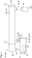
- Fig. 1 is shown schematically in a perspective view a flushing system 190 with a flushing device 10 and a gas-conducting line 100 with a control section 110.
- the flushing device 10 is designed for flushing the control section 110 of the gas-conducting line 100.
- the flushing device 10 comprises a supply interface 30 for coupling the flushing device 10 to the control section 110 and for supplying flushing gas I to the control section 110, a flushing gas interface 40 for coupling a flushing gas source 150 to the flushing device 10, wherein the supply interface 30 and the flushing gas interface 40 are connected to one another in a fluid-communicating manner and a Extraction interface 20 for coupling the purging device 10 to the control section 110 and for extracting gas G from the control section 110, wherein the purging device 10 further comprises a measuring device 50 downstream of the extraction interface 20 for measuring the gas G from the control section 110.
- the measuring device 50 comprises a pressure measuring device 52 for measuring a pressure within the measuring device 50, a concentration measuring device 54 for measuring a gas concentration within the measuring device 50 and in the surroundings of the measuring device 50 and a mass flow measuring device 56 for measuring a mass flow within the measuring device 50.
- the measuring device 50 comprises an evaluation device 58 for evaluating the recorded measured values and a transmitting and/or receiving device 60 for transmitting and/or receiving the measured and/or evaluated measured values.
- the purge gas interface 40 is coupled to a purge gas source 150 of the purge device 10, wherein the purge gas source 150 is designed as a mobile purge gas source 150.
- the supply interface 30 and the removal interface 20 are designed for detachable coupling to the control section 110.
- the purge gas interface 40 is further designed for detachable coupling to the purge gas source 150.
- the removal interface 20 comprises a locking device 14, wherein the locking device 14 can be locked in a fluid-tight manner.
- the purging device 10 comprises, downstream of the extraction interface 20 and the measuring device 50, a discharge interface 70 for coupling the purging device 10 to the gas-carrying line 100, here downstream of the control section 110, for discharging the extracted gas G from the control section 110.
- the extraction interface 20 comprises a filter device 80 for filtering the extracted gas G from the control section 110.
- the feed interface 30 comprises a check valve device 90 for blocking a fluid flow of the gas G and the purging gas I in one direction.
- the measuring device 50 comprises a passive explosion protection device 12 in the form of a cast casing.
- the control section 110 can be blocked in a fluid-tight manner against the gas-carrying line 100 by two blocking devices 112 of the gas-carrying line 100.
- FIG. 2 A further flushing system 190 with a flushing device 10 and a gas-carrying line 100 with a control section 110 is shown schematically in a perspective view.
- the flushing device 10 comprises downstream of the extraction interface 20 and the measuring device 50 a discharge interface 70 for coupling the flushing device 10 with a Flushing storage device 72 for discharging the extracted gas G from the control section 110.
- the flushing method 200 comprises, in a first method step, the coupling 202 of a supply interface 30 of the flushing device 10 to a control section 110 of the gas-carrying line 100.
- the flushing method 200 comprises, in a further method step, the coupling 204 of a purge gas interface 40 of the flushing device 10 to a purge gas source 150.
- the flushing method 200 comprises, in a further method step, the coupling 206 of a removal interface 20 of the flushing device 10 to a control section 110 of the gas-carrying line 100.
- the flushing method 200 comprises, in a further method step, the supply 208 of purge gas I into the control section 110 through the supply interface 30.
- the flushing method 200 comprises, in a further method step, the removal 210 of gas G from the control section 110 through the removal interface 20.
- the flushing method 200 comprises, in a further method step, the measuring 212 of the gas G extracted from the control section 110.
- the supply 208 of purge gas I into the control section 110 and the extraction 210 of gas G from the control section 110 takes place depending on the measured extracted gas G from the control section 110.
Landscapes
- Engineering & Computer Science (AREA)
- Mechanical Engineering (AREA)
- General Engineering & Computer Science (AREA)
- Sampling And Sample Adjustment (AREA)
Abstract
Description
- Die vorliegende Erfindung betrifft eine Spülvorrichtung zur Spülung eines Kontrollabschnitts einer gasführenden Leitung. Ferner betrifft die Erfindung ein Spülverfahren zur Spülung eines Kontrollabschnitts einer gasführenden Leitung durch eine Spülvorrichtung. Auch betrifft die Erfindung ein Spülsystem mit einer Spülvorrichtung und einer gasführenden Leitung mit einem Kontrollabschnitt.
- Die derzeitig öffentlich bekannten Gasnetze umfassen eine Vielzahl an Vorrichtungen, die beispielsweise für Wartungsarbeiten, Reparaturen und/oder ein Austauschen gegen das Gasnetz fluidkommunizierend gesperrt werden können. Die Vorgaben für den Betrieb von beispielsweise Gasdruckregel- und Messanlagen unterliegt in Deutschland dem Regelwerk des DVGWs. Insbesondere werden in den DVGW-Arbeitsblättern DVGW G491 und G495 Vorgaben getroffen, die den Stand der Technik abbilden und die notwendigen Arbeitsschritte vorgeben.
- Beispielhaft werden bei bekannten Gasdruckregel- und Messanlagen und auch bei anderen gastechnische Anlagen mit gleicher Problematik von Emissionen, aktuell bei Funktionskontrollen, Wartungsarbeiten und/oder anderen Arbeiten das in den abgesperrten Teilen der Anlange mit erhöhtem Druck stehende Gas über einen Regler in das nachgelagerte Netz abgeführt. Nachdem der Druckausgleich oder ein minimal technischer Restdruck gegenüber dem nachgelagerten Netz hergestellt ist, wird zumeist eine hintere Absperrarmatur geschlossen. Das restliche Gas wird nun zumeist über Ausblaseleitungen gegen Atmosphäre entspannt. Dabei entweichen die Restmengen an Gas mit Atmosphärendruck in den Leitungen beim Öffnen von Filtern, Reglern oder anderen Armaturen.
- Nach den entsprechenden Arbeiten, beispielsweise Wartungsarbeiten, wird die Luft in den Anlagenteilen durch Öffnen eines vorderen Absperrelements über die Ausblaseleitungen mit Hilfe des regulären Transportmediums in die Atmosphäre geschoben. Dabei entweichen zumeist erneut unbestimmte Mengen des Mediums.
- Es ist daher Aufgabe der vorliegenden Erfindung, die oben beschriebenen Nachteile im Stand der Technik zu beheben oder zumindest teilweise zu beheben. Insbesondere ist es Aufgabe der Erfindung, eine Spülvorrichtung bereitzustellen, mit der eine Spülung eines Kontrollabschnitts einer gasführenden Leitung besonders einfach ermöglicht wird, insbesondere wobei ein Austritt des Gases in die Atmosphäre reduziert und/oder verhindert wird. Insbesondere ist es ferner die Aufgabe der Erfindung ein Spülverfahren zur Spülung eines Kontrollabschnitts einer gasführenden Leitung durch eine Spülvorrichtung sowie ein Spülsystem umfassend eine Spülvorrichtung und eine gasführende Leitung mit einem Kontrollabschnitt bereitzustellen.
- Die erfinderische Lösung hilft bei der Reduktion von Emissionen von brennbaren Gasen aus der gasführenden Leitung in die Atmosphäre, die durch die Arbeiten, wie beispielsweise Funktionskontrollen und/oder Wartungsarbeiten an Anlagenteilen, derzeit zumeist entstehen.
- Die voranstehende Aufgabe wird durch die Patentansprüche gelöst. Insbesondere wird die Aufgabe gelöst durch eine Spülvorrichtung zur Spülung eines Kontrollabschnitts einer gasführenden Leitung mit den Merkmalen des unabhängigen Anspruchs 1. Ferner wird die Aufgabe gelöst durch ein Spülverfahren zur Spülung eines Kontrollabschnitts einer gasführenden Leitung durch eine Spülvorrichtung mit den Merkmalen des unabhängigen Anspruchs 11 und durch ein Spülsystem umfassend eine Spülvorrichtung und eine gasführende Leitung mit einem Kontrollabschnitt mit den Merkmalen des unabhängigen Anspruchs 13. Weitere Vorteile und Details der Erfindung ergeben sich aus den Unteransprüchen, der Beschreibung und den Zeichnungen. Dabei gelten Merkmale, die im Zusammenhang mit der erfindungsgemäßen Spülvorrichtung beschrieben sind, selbstverständlich auch im Zusammenhang mit dem erfindungsgemäßen Spülverfahren, dem erfindungsgemäßen Spülsystem und jeweils umgekehrt, sodass bezüglich der Offenbarung zu den einzelnen Erfindungsaspekten stets wechselseitig Bezug genommen wird beziehungsweise werden kann.
- Gemäß einem ersten Aspekt der Erfindung wird die Aufgabe gelöst durch eine Spülvorrichtung zur Spülung eines Kontrollabschnitts einer gasführenden Leitung, die Spülvorrichtung umfassend eine Zuführschnittstelle zur Kopplung der Spülvorrichtung mit dem Kontrollabschnitt und zur Zuführung von Spülgas in den Kontrollabschnitt, eine Spülgasschnittstelle zum Kopplung einer Spülgasquelle mit der Spülvorrichtung, wobei die Zuführschnittstelle und die Spülgasschnittstelle fluidkommunizierend miteinander verbunden sind und eine Entnahmeschnittstelle zur Kopplung der Spülvorrichtung mit dem Kontrollabschnitt und zur Entnahme von Gas aus dem Kontrollabschnitt, wobei die Spülvorrichtung ferner eine Messvorrichtung stromabwärts der Entnahmeschnittstelle zur Messung des Gases aus dem Kontrollabschnitt umfasst.
- Die gasführende Leitung ist im Rahmen der Erfindung bevorzugt als Erdgas- und/oder Wasserstoffleitung zu verstehen. Die erfindungsgemäße Spülvorrichtung setzt in der Praxis bevorzugt nach dem voranstehend beschriebenen Arbeitsschritt des Druckausgleichs des Kontrollabschnitts gegenüber der gasführenden Leitung und/oder bei einem Kontrollabschnitt mit minimalem technischen Restdruck gegenüber einem stromabwärts nachgelagerten Netz und einem Schließen einer hinteren Sperrvorrichtung, beispielsweise in Form einer Absperrarmatur, am hinteren Ende des Kontrollabschnitts an. Die erfindungsgemäße Spülvorrichtung ermöglicht bevorzugt die Zuführung eines Spülgases, bevorzugt eines Inertisierungsgas, beispielsweise Stickstoff, in den Kontrollabschnitt, um das restliche Gas in dem Kontrollabschnitt mit einem passenden Überdruck aus einer Spülgasquelle, beispielsweise einer Gasflasche, und/oder durch eine Fördervorrichtung der Spülgasquelle aus dem Kontrollabschnitt zu drücken. Eine Verwendung von Luft als Spülgas ist aufgrund des Explosionsschutzes selbstverständlich nicht zulässig. Der Kontrollabschnitt ist ferner bevorzugt durch eine vordere Sperrvorrichtung fluidkommunizierend gegen die gasführende Leitung stromaufwärts des Kontrollabschnitts gesperrt. Mit anderen Worten ist der Kontrollabschnitt bevorzugt durch eine vordere und eine hintere Sperrvorrichtung gegen die gasführende Leitung gesperrt.
- Die Spülvorrichtung ermöglicht eine Kopplung der Zuführschnittstelle und der Entnahmeschnittstelle jeweils mit dem Kontrollabschnitt. Die Kopplung der Zuführschnittstelle und der Entnahmeschnittstelle jeweils mit dem Kontrollabschnitt ist bevorzugt lösbar, insbesondere werkzeuglos lösbar, ausgestaltet. Somit ermöglicht die Spülvorrichtung eine Zufuhr von Spülgas in den Kontrollabschnitt durch die Zuführschnittstelle und eine Entnahme von Gas und/oder Spülgas aus dem Kontrollabschnitt durch die Entnahmeschnittstelle. Mit anderen Worten ermöglicht die Spülvorrichtung eine Spülung des Kontrollabschnitts mit Spülgas und somit eine Entnahme des Gases aus dem Kontrollabschnitt.
- Die Entnahmeschnittstelle ist bevorzugt, wie in einem späteren Abschnitt ausführlich beschrieben, stromabwärts mit der gasführenden Leitung oder einer Speichervorrichtung zur Abführung des Gases aus dem Kontrollbereich verbunden.
- Die Spülvorrichtung ist besonders vorteilhaft, weil sie eine Messvorrichtung stromabwärts der Entnahmeschnittstelle zur Messung des Gases aus dem Kontrollabschnitt umfasst. Somit ermöglicht die Messvorrichtung eine Fortschrittsüberprüfung des Spülvorgangs und/oder eine Überprüfung, ob noch Gas aus dem Kontrollabschnitt durch das zugeführte Spülgas gedrückt wird. Beispielhaft und anschaulich formiert wird durch die Spülvorrichtung der Gehalt an brennbarem Gas über zumindest einen entsprechenden Sensor der Messvorrichtung erfasst. Alternativ oder zusätzlich ist der Massenfluss durch zumindest einen entsprechenden Sensor der Messvorrichtung detektierbar. Damit besteht die Möglichkeit das geförderte Volumen in dem entsprechenden Anlagenabschnitt mit dem Restgehalt an brennbarem Gas zu vergleichen um beispielsweise eine Verifizierung der Messergebnisse sicherzustellen. Der Arbeitsschritt des Spülens kann nun manuell oder automatisiert durch die Spülvorrichtung und/oder einen Anwender ausgeführt und/oder gestoppt werden.
- Die Spülvorrichtung ist bevorzugt als mobile Spülvorrichtung zu verstehen. Mit anderen Worten ist die Spülvorrichtung bevorzugt als tragbare Spülvorrichtung zu verstehen und somit für einen Anwender vorteilhaft, flexibel und schnell an einer Vielzahl an Kontrollabschnitten von gasführenden Leitungen einsetzbar. Anschaulich und bespielhaft formuliert ist die Spülvorrichtung innerhalb eines Gehäuses und/oder eines Koffers ausgestaltet.
- Eine derart ausgestaltete Spülvorrichtung ist besonders vorteilhaft, da eine Spülung eines Kontrollabschnitts einer gasführenden Leitung besonders einfach ermöglicht wird, wobei ein Austritt von Gas aus dem Kontrollabschnitt in die Umgebung vorteilhaft reduziert oder vermieden wird.
- Gemäß einer bevorzugten Weiterentwicklung der Erfindung kann bei einer Spülvorrichtung vorgesehen sein, dass die Messvorrichtung eine Druckmessvorrichtung zur Messung zumindest eines Drucks innerhalb der Messvorrichtung, eine Konzentrationsmessvorrichtung zur Messung zumindest einer Gaskonzentration innerhalb der Messvorrichtung und/oder in der Umgebung der Messvorrichtung und/oder eine Massenstrommessvorrichtung zur Messung zumindest eines Massenstroms innerhalb der Messvorrichtung umfasst. Die Messvorrichtung dient im Rahmen der Erfindung der Überprüfung, ob der Kontrollabschnitt frei von brennbarem Gas ist und folglich ausschließlich oder im Wesentlichen ausschließlich mit Spülgas gefüllt worden ist. Die Formulierung "X oder im Wesentlichen X" soll im Rahmen der Erfindung als mögliche, geringe Abweichung, beispielsweise aufgrund von Fertigungstoleranzen, Material- und/oder Prozesseigenschaften verstanden werden, ohne die zugrundeliegende, beabsichtigte Funktion des Merkmals zu verändern. Die Messvorrichtung umfasst zumindest eine Druckmessvorrichtung zur Messung zumindest eines Drucks innerhalb der Messvorrichtung. Die Messvorrichtung umfasst zusätzlich oder alternativ zumindest eine Konzentrationsmessvorrichtung zur Messung zumindest einer Gaskonzentration innerhalb der Messvorrichtung und/oder in der Umgebung der Messvorrichtung. Die Messung der Gaskonzentration in der Umgebung der Messvorrichtung ist dabei bevorzugt als Messung einer möglichen Leckage der Spülvorrichtung und/oder der gasführenden Leitung zu verstehen. Die Messvorrichtung umfasst zusätzlich oder alternativ zumindest eine Massenstrommessvorrichtung zur Messung zumindest eines Massenstroms innerhalb der Messvorrichtung. Durch eine derart ausgestaltete Messvorrichtung wird beispielsweise vorteilhaft ermöglicht das geförderte Volumen aus dem entsprechenden Kontrollabschnitt mit dem Restgehalt an brennbarem Gas zu vergleichen um beispielsweise eine Verifizierung der Messergebnisse sicherzustellen. Bevorzugt umfasst die Messvorrichtung zumindest eine optische und/oder akustische Ausgabevorrichtung zur Ausgabe von Daten und oder Warnungen.
- Eine derart ausgestaltete Spülvorrichtung ist durch die Ausgestaltung der Messvorrichtung besonders vorteilhaft, da eine Spülung eines Kontrollabschnitts einer gasführenden Leitung sowie die Erfassung der Spülung besonders einfach ermöglicht wird, wobei ein Austritt von Gas aus dem Kontrollabschnitt in die Umgebung vorteilhaft reduziert oder vermieden wird.
- Gemäß einer bevorzugten Weiterentwicklung der Erfindung kann bei einer Spülvorrichtung vorgesehen sein, dass die Messvorrichtung eine Auswertevorrichtung zur Auswertung der erfassten Messwerte umfasst und/oder dass die Messvorrichtung eine Sende- und/oder Empfangsvorrichtung zum Senden und/oder Empfangen der gemessenen und/oder ausgewerteten Messwerte umfasst. Die erfindungsgemäße Auswertevorrichtung ermöglicht bevorzugt eine Gasauswertung des Gases und/oder des Spülgases aus dem Kontrollabschnitt. Eine Auswertung umfasst bevorzugt eine Auswertung der Zusammensetzung des Fluides, insbesondere einer prozentualen Zusammensetzung. Die gemessenen und/oder ausgewerteten Messwerte werden bevorzugt an eine Servervorrichtung und/oder eine Speichervorrichtung gesendet und/oder von diesen Vorgabedaten und/oder Vergleichsdaten empfangen. Die Servervorrichtung und/oder Speichervorrichtung sind bevorzugt separat von der Spülvorrichtung oder als Bestandteil der Spülvorrichtung definiert und/oder ausgestaltet. Eine derart ausgestaltete Spülvorrichtung ist durch die Auswertevorrichtung und/oder durch die Sende- und/oder Empfangsvorrichtung besonders vorteilhaft, da eine Spülung eines Kontrollabschnitts einer gasführenden Leitung sowie die Auswertung der Spülung besonders einfach ermöglicht wird, wobei ein Austritt von Gas aus dem Kontrollabschnitt in die Umgebung vorteilhaft reduziert oder vermieden wird.
- Gemäß einer bevorzugten Weiterentwicklung der Erfindung kann bei einer Spülvorrichtung vorgesehen sein, dass die Spülgasschnittstelle mit einer Spülgasquelle der Spülvorrichtung gekoppelt ist, insbesondere wobei die Spülgasquelle als mobile Spülgasquelle oder als stationäre Spülgasquelle ausgestaltet ist. Die Spülgasquelle ist als Bestandteil der Spülvorrichtung oder als separate Spülgasquelle ausgestaltet. Die Spülgasquelle ist als mobile Spülgasquelle, beispielsweise als Spülgastank, oder als stationäre Spülgasquelle, beispielsweise als Spülgasnetz, zu verstehen. Eine mobile Spülgasquelle ist in Kombination mit einer mobilen Spülvorrichtung besonders vorteilhaft, da somit eine vollständig mobile und damit flexible Verwendung der Spülvorrichtung ermöglicht wird. Eine stationäre Spülgasquelle ist besonders vorteilhaft, da keine Volumenbegrenzung der Spülgasquelle den Vorgang der Spülung des Kontrollabschnitts begrenzt. Die Spülgasquelle ermöglicht eine Bereitstellung von Spülgas für die Spülvorrichtung zur Spülung eines Kontrollabschnitts einer gasführenden Leitung. Die Förderung des Spülgases erfolgt bevorzugt durch das Druckverhältnis der Spülgasquelle in Relation zum Kontrollabschnitt. Alternativ oder zusätzlich umfasst die Spülgasquelle eine Fördervorrichtung zur Förderung des Spülgases in den Kontrollabschnitt. Das Spülgas ist, wie voranstehend beschrieben, bevorzugt als Inertisierungsgas, insbesondere als Stickstoff, zu verstehen. Stickstoff ist als Spülgas zur Spülung eines Kontrollabschnitts einer gasführenden Leitung besonders vorteilhaft, da Stickstoff kostengünstig, schwerer als Erdgas und nicht brennbar ist. Eine derart ausgestaltete Spülvorrichtung ist durch die Ausgestaltung der Spülgasquelle besonders vorteilhaft, da eine Spülung eines Kontrollabschnitts einer gasführenden Leitung besonders einfach ermöglicht wird, wobei ein Austritt von Gas aus dem Kontrollabschnitt in die Umgebung vorteilhaft reduziert oder vermieden wird.
- Gemäß einer bevorzugten Weiterentwicklung der Erfindung kann bei einer Spülvorrichtung vorgesehen sein, dass die Zuführschnittstelle und/oder die Entnahmeschnittstelle zur lösbaren Kopplung mit dem Kontrollabschnitt ausgestaltet sind und/oder dass die Spülgasschnittstelle zur lösbaren Kopplung mit der Spülgasquelle ausgestaltet ist. Die Kopplung der Zuführschnittstelle und/oder der Entnahmeschnittstelle jeweils mit dem Kontrollabschnitt ist bevorzugt lösbar, insbesondere werkzeuglos lösbar, ausgestaltet. Somit ermöglicht die Spülvorrichtung eine einfache Kopplung der Spülvorrichtung mit dem Kontrollabschnitt und/oder der gasführenden Leitung und anschließend eine Zufuhr von Spülgas in den Kontrollabschnitt durch die Zuführschnittstelle und eine Entnahme von Gas und/oder Spülgas aus dem Kontrollabschnitt durch die Entnahmeschnittstelle. Mit anderen Worten ermöglicht die Spülvorrichtung eine einfache Montage, eine Spülung des Kontrollabschnitts mit Spülgas und somit eine Entnahme des Gases aus dem Kontrollabschnitt sowie eine anschließende einfache Demontage der Spülvorrichtung. Die lösbaren Kopplungen sind beispielsweise als Verschraubungen und/oder Steckkopplungen ausgestaltet. Die Kopplungen umfassen bevorzugt flexible Schläuche und/oder sind bevorzugt für Drücke bis 70 bar oder bis 100 bar ausgestaltet. Eine derart ausgestaltete Spülvorrichtung ist durch die Ausgestaltung der Kopplungen besonders vorteilhaft, da eine Montage der Spülvorrichtung, Demontage der Spülvorrichtung und Spülung eines Kontrollabschnitts einer gasführenden Leitung besonders einfach ermöglicht wird, wobei ein Austritt von Gas aus dem Kontrollabschnitt in die Umgebung vorteilhaft reduziert oder vermieden wird.
- Gemäß einer bevorzugten Weiterentwicklung der Erfindung kann bei einer Spülvorrichtung vorgesehen sein, dass die Zuführschnittstelle, die Entnahmeschnittstelle und/oder die Spülgasschnittstelle zumindest eine Sperrvorrichtung umfasst, wobei die zumindest eine Sperrvorrichtung fluiddicht sperrbar ist. Eine Sperrvorrichtung ist im Rahmen der Erfindung bevorzugt als Ventil, als Absperrarmatur, als manuelle Sperrvorrichtung und/oder als automatische Sperrvorrichtung zu verstehen. Die zumindest eine Sperrvorrichtung ermöglicht bevorzugt eine Sperrung einer fluidkommunizierenden Verbindung des entsprechenden Abschnitts. Beispielsweise ermöglicht eine Sperrvorrichtung der Zuführschnittstelle in Kombination mit einer Sperrvorrichtung der Entnahmeschnittstelle bevorzugt eine Sperrung des Kontrollabschnitts nach abgeschlossenem Spülvorgang. Eine derart ausgestaltete Spülvorrichtung ist durch die zumindest eine Sperrvorrichtung besonders vorteilhaft, da eine Spülung eines Kontrollabschnitts einer gasführenden Leitung besonders einfach ermöglicht wird, wobei ein Austritt von Gas aus dem Kontrollabschnitt in die Umgebung vorteilhaft reduziert oder vermieden wird. Ferner ermöglicht die zumindest eine Sperrvorrichtung vorteilhaft die Sperrung von fluidkommunizierenden Verbindungen und somit eine vorteilhafte Umgebung für Wartungsarbeiten, Reparaturen und/oder Messungen an dem Kontrollabschnitt und/oder der gasführenden Leitung.
- Gemäß einer bevorzugten Weiterentwicklung der Erfindung kann bei einer Spülvorrichtung vorgesehen sein, dass die Spülvorrichtung stromabwärts der Entnahmeschnittstelle und der Messvorrichtung eine Abführschnittstelle zur Kopplung der Spülvorrichtung mit der gasführenden Leitung, insbesondere stromabwärts des Kontrollabschnitts, und/oder mit einer Spülspeichervorrichtung zur Abführung des entnommenen Gases aus dem Kontrollabschnitt umfasst. Die Entnahmeschnittstelle ist über die Abführschnittstelle bevorzugt stromabwärts mit der gasführenden Leitung, insbesondere stromabwärts des Kontrollabschnitts, oder einer Speichervorrichtung zur Abführung des Gases aus dem Kontrollbereich verbunden. Das entnommene Gas aus dem Kontrollabschnitt wird folglich bevorzugt dem nachgelagerten Gasnetz oder einer Spülspeichervorrichtung zugeführt. Die Spülspeichervorrichtung ist beispielsweise als ein Gastank ausgestaltet und dient der Abführung des entnommenen Gases aus dem Kontrollabschnitt. Bevorzugt wird jedoch die Kopplung der Abführschnittstelle mit der gasführenden Leitung stromabwärts des Kontrollabschnitts. Die Abführschnittstelle ist bevorzugt lösbar, insbesondere werkzeuglos lösbar, mit der gasführenden Leitung und/oder der Spülspeichervorrichtung koppelbar. Eine derart ausgestaltete Spülvorrichtung ist durch die Abführschnittstelle besonders vorteilhaft, da eine Spülung eines Kontrollabschnitts einer gasführenden Leitung besonders einfach ermöglicht wird, wobei eine definierte Abführung von Gas aus dem Kontrollabschnitt in die gasführende Leitung und/oder in die Spülspeichervorrichtung ermöglicht wird.
- Gemäß einer bevorzugten Weiterentwicklung der Erfindung kann bei einer Spülvorrichtung vorgesehen sein, dass die Entnahmeschnittstelle, die Messvorrichtung und/oder die Abführschnittstelle eine Filtervorrichtung zur Filterung des entnommenen Gases aus dem Kontrollabschnitt umfasst. Die erfindungsgemäße Filtervorrichtung ist bevorzugt als Membran zur Filterung des entnommenen Gases aus dem Kontrollabschnitt ausgestaltet. Zusätzlich oder alternativ ist die erfindungsgemäße Filtervorrichtung bevorzugt als Membran zur Separierung von Gas und Spülgas aus dem Kontrollabschnitt ausgestaltet, insbesondere um einen unnötigen und/oder technisch nicht zugelassen Anteil an Spülgas im nachgelagerten Netz zu reduzieren und/oder vermeiden und/oder die Abgabe von brennbarem Gas in die Atmosphäre zu reduzieren und/oder vermeiden. Bevorzugt umfasst die Entnahmeschnittstelle stromabwärts der Filtervorrichtung eine Ausbläservorrichtung. Die Ausbläservorrichtung dient bevorzugt der Abführung des Gases in Verbindung mit einer Filtervorrichtung, insbesondere einer Separationsmembrane zur Separierung von Gas und Spülgas, um geringe Mengen Mischgas und/oder abgeschiedenes Spülgas in die Atmosphäre zu geben. Bevorzugt ermöglicht die Filtervorrichtung eine Filterung und einen Durchlass des Gases aus dem Kontrollabschnitt und eine Blockierung des Spülgases und/oder anderer Fluide. Eine derartige Filtervorrichtung ermöglicht vorteilhaft eine Qualitätssicherung des Gases in der gasführenden Leitung und eine Vermeidung von Unreinheiten in dem Gas. Eine derart ausgestaltete Spülvorrichtung ist durch die Filtervorrichtung besonders vorteilhaft, da eine Spülung eines Kontrollabschnitts einer gasführenden Leitung besonders einfach ermöglicht wird, wobei eine definierte Abführung von Gas, insbesondere ausschließlich Gas, aus dem Kontrollabschnitt bevorzugt in die gasführende Leitung ermöglicht wird.
- Gemäß einer bevorzugten Weiterentwicklung der Erfindung kann bei einer Spülvorrichtung vorgesehen sein, dass die Entnahmeschnittstelle, die Zuführschnittstelle, die Spülgasschnittstelle, die Messvorrichtung und/oder die Abführschnittstelle eine Rücksperrventilvorrichtung zur Sperrung eines Fluidstroms des Gases und/oder des Spülgases in zumindest eine Richtung umfasst. Eine Rücksperrventilvorrichtung ermöglicht eine lediglich einseitige Durchströmung des entsprechenden Leitungsabschnitts und folglich eine Sperrung eines Gasflusses entgegen der definierten Flussrichtung der Rücksperrventilvorrichtung. Dadurch ermöglicht die Spülvorrichtung unabhängig von den jeweiligen Druckverhältnissen eine Sicherung der Flussrichtung des Gases und/oder des Spülgases und/oder eine Verhinderung einer ungewollten Flussrichtung des Gases und/oder des Spülgases. Beispielhaft verhindert eine Rücksperrventilvorrichtung der Spülgasschnittstelle einen Rückfluss des Spülgases zur Spülgasquelle, falls in der Spülgasquelle der Druck auf ein Niveau unterhalb des Kontrollabschnitts fällt. Eine derart ausgestaltete Spülvorrichtung ist durch die zumindest eine Rücksperrventilvorrichtung besonders vorteilhaft, da eine Spülung eines Kontrollabschnitts einer gasführenden Leitung besonders einfach ermöglicht wird, wobei eine definierte Führung von Gas und/oder Spülgas ermöglicht wird.
- Gemäß einer bevorzugten Weiterentwicklung der Erfindung kann bei einer Spülvorrichtung vorgesehen sein, dass die Spülvorrichtung und/oder die Messvorrichtung eine aktive und/oder passive Explosionsschutzvorrichtung umfasst. Eine Explosionsschutzvorrichtung ist bevorzugt zum Schutz der Spülvorrichtung gegen Explosionen und/oder gegen explosionsfördernde Umstände zu verstehen. Beispielhaft ist eine passive Explosionsschutzvorrichtung als eine Vergussmasse zumindest abschnittsweise um die Messvorrichtung zu verstehen, um eine Vermeidung von Hitze- und/oder Funkenquellen in der Nähe der gasführenden Leitung zu vermeiden. Eine aktive Explosionsschutzvorrichtung ist beispielsweise als Erfassungsvorrichtung zum Erfassen von Gasleckagen, Hitzeentwicklungen und/oder zur Fehlererfassung der Spülvorrichtung zu verstehen. Eine derart ausgestaltete Spülvorrichtung ist durch die zumindest eine Explosionsschutzvorrichtung besonders vorteilhaft, da eine Spülung eines Kontrollabschnitts einer gasführenden Leitung besonders einfach ermöglicht wird, wobei eine Sicherheit des Betriebs der Spülvorrichtung und/oder der gasführenden Leitung vorteilhaft ermöglicht wird.
- Gemäß einem zweiten Aspekt der Erfindung wird die Aufgabe durch ein Spülverfahren zur Spülung eines Kontrollabschnitts einer gasführenden Leitung durch eine Spülvorrichtung gelöst. Das Spülverfahren umfassend:
- Kopplung einer Zuführschnittstelle der Spülvorrichtung mit einem Kontrollabschnitt der gasführenden Leitung,
- Kopplung einer Spülgasschnittstelle der Spülvorrichtung mit einer Spülgasquelle,
- Kopplung einer Entnahmeschnittstelle der Spülvorrichtung mit einem Kontrollabschnitt der gasführenden Leitung,
- Zuführung von Spülgas in den Kontrollabschnitt durch die Zuführschnittstelle,
- Entnahme von Gas aus dem Kontrollabschnitt durch die Entnahmeschnittstelle,
- Messen des entnommenen Gases aus dem Kontrollabschnitt.
- Die zuvor und die im Nachfolgenden beschrieben Verfahrensschritte können, wenn nicht explizit anderweitig angegeben, einzeln, zusammen, einfach, mehrfach, zeitlich parallel und/oder nacheinander in beliebiger Reihenfolge ausgeführt werden. Eine Benennung als beispielsweise "erster Verfahrensschritt" und "zweiter Verfahrensschritt" bedingt keine zeitliche Reihenfolge und/oder Priorisierung. Eine bevorzugte Reihenfolge der Verfahrensschritte sieht vor, dass die Verfahrensschritte in der aufgeführten Reihenfolge ausgeführt werden.
- Bevorzugt ist die Spülvorrichtung gemäß dem ersten Aspekt ausgestaltet, sodass sich bei dem beschriebenen Spülverfahren sämtliche Vorteile ergeben, die bereits zu der Spülvorrichtung gemäß dem ersten Aspekt der Erfindung beschrieben worden sind. Bevorzugt umfasst das Spülverfahren eine Auswertung des gemessenen Gases. Bevorzugt umfasst das Spülverfahren ein Abführen des entnommenen Gases aus dem Kontrollabschnitt über eine Abführschnittstelle der Spülvorrichtung in die gasführende Leitung, insbesondere stromabwärts des Kontrollabschnitts, und/oder in eine Spülspeichervorrichtung der Spülvorrichtung. Bevorzugt umfasst das Spülverfahren ein Sperren zumindest einer Sperrvorrichtung der Spülvorrichtung, insbesondere der Zuführschnittstelle, der Entnahmeschnittstelle und/oder der Spülgasschnittstelle. Das Sperren erfolgt bevorzugt in Abhängig von dem gemessenen entnommenen Gas aus dem Kontrollabschnitt. Ein derart ausgestaltetes Spülverfahren ist besonders vorteilhaft, da eine Spülung eines Kontrollabschnitts einer gasführenden Leitung besonders einfach ermöglicht wird, wobei ein Austritt von Gas aus dem Kontrollabschnitt in die Umgebung vorteilhaft reduziert oder vermieden wird.
- Gemäß einer bevorzugten Weiterentwicklung der Erfindung kann bei einem Spülverfahren vorgesehen sein, dass die Zuführung von Spülgas in den Kontrollabschnitt und/oder die Entnahme von Gas aus dem Kontrollabschnitt in Abhängigkeit von dem gemessenen entnommenen Gas aus dem Kontrollabschnitt erfolgt. Für die abhängige Zuführung und/oder Entnahme umfasst die Spülvorrichtung bevorzugt Sperrvorrichtungen und/oder Stellvorrichtungen für die Sperrvorrichtungen, wobei beispielsweise die Stellvorrichtungen die Sperrvorrichtungen in Abhängigkeit von dem gemessenen entnommenen Gas aus dem Kontrollabschnitt öffnen und/oder schließen. Bevorzugt ermöglicht das Spülverfahren einen Vergleich des gemessenen Gases mit zumindest einem Grenzwert, wobei bei Erreichen oder Unterschreiten des Grenzwerts die Zuführung von Spülgas gestoppt wird. Somit ermöglicht das erfindungsgemäße Spülverfahren vorteilhaft eine Überprüfung der Spülung und ein bevorzugt automatisches Stoppen des Spülverfahrens, wenn nur noch der Grenzwert des Gases oder kein Gas mehr aus dem Kontrollabschnitt gemessen wird. Ein derart ausgestaltetes Spülverfahren ist besonders vorteilhaft, da eine Spülung eines Kontrollabschnitts einer gasführenden Leitung besonders einfach und effizient ermöglicht wird, wobei ein Austritt von Gas aus dem Kontrollabschnitt in die Umgebung vorteilhaft reduziert oder vermieden wird.
- Gemäß einem dritten Aspekt der Erfindung wird die Aufgabe durch ein Spülsystem umfassend eine Spülvorrichtung und eine gasführende Leitung mit einem Kontrollabschnitt gelöst. Die Spülvorrichtung ist gemäß dem ersten Aspekt ausgestaltet, sodass sich bei dem beschriebenen Spülsystem sämtliche Vorteile ergeben, die bereits zu der Spülvorrichtung gemäß dem ersten Aspekt der Erfindung beschrieben worden sind. Die gasführende Leitung weist bevorzugt entsprechende Gegenkopplungen für die Kopplung mit der Zuführschnittstelle, der Entnahmeschnittstelle und/oder der Abführschnittstelle auf. Ein derart ausgestaltetes Spülsystem ist besonders vorteilhaft, da eine Spülung eines Kontrollabschnitts einer gasführenden Leitung besonders einfach ermöglicht wird, wobei ein Austritt von Gas aus dem Kontrollabschnitt in die Umgebung vorteilhaft reduziert oder vermieden wird.
- Gemäß einer bevorzugten Weiterentwicklung der Erfindung kann bei einem Spülsystem vorgesehen sein, dass der Kontrollabschnitt durch zumindest eine Sperrvorrichtung der gasführenden Leitung, bevorzugt durch zwei Sperrvorrichtungen, gegen die gasführende Leitung fluiddicht sperrbar ist. Um einen definierten Abschnitt für Wartungsarbeiten und/oder Reparaturen in dem Kontrollabschnitt zu schaffen, ist es besonders vorteilhaft die fluidkommunizierende Verbindung dieses Abschnitts gegen den Rest der gasführenden Leitung durch die zumindest eine Sperrvorrichtung sperren zu können. Ein derart ausgestaltetes Spülsystem ist durch die zumindest eine Sperrvorrichtung besonders vorteilhaft, da eine Spülung eines definierten Kontrollabschnitts einer gasführenden Leitung besonders einfach ermöglicht wird, wobei ein Austritt von Gas aus dem Kontrollabschnitt in die Umgebung vorteilhaft reduziert oder vermieden wird.
- Gemäß einer bevorzugten Weiterentwicklung der Erfindung kann bei einem Spülsystem vorgesehen sein, dass das Spülsystem zum Ausführen des Spülverfahrens gemäß dem zweiten Aspekt ausgestaltet ist, sodass sich bei dem beschriebenen Spülsystem sämtliche Vorteile ergeben, die bereits zu dem Spülverfahren gemäß dem zweiten Aspekt der Erfindung beschrieben worden sind.
- Eine erfindungsgemäße Spülvorrichtung, ein Spülsystem sowie ein Spülverfahren werden nachfolgend anhand von Zeichnungen näher erläutert. Es zeigen jeweils schematisch:
- Figur 1
- in einer perspektivischen Ansicht ein Spülsystem mit einer Spülvorrichtung und einer gasführenden Leitung mit einem Kontrollabschnitt,
- Figur 2
- in einer perspektivischen Ansicht ein weiteres Spülsystem mit einer Spülvorrichtung und einer gasführenden Leitung mit einem Kontrollabschnitt, und
- Figur 3
- in einem Flussdiagramm eine erfindungsgemäße Ausgestaltung des Spülverfahrens.
- Elemente mit gleicher Funktion und Wirkungsweise sind in den
Fig. 1 bis 3 jeweils mit denselben Bezugszeichen versehen. - In
Fig. 1 ist schematisch in einer perspektivischen Ansicht ein Spülsystem 190 mit einer Spülvorrichtung 10 und einer gasführenden Leitung 100 mit einem Kontrollabschnitt 110 gezeigt. Die Spülvorrichtung 10 ist zur Spülung des Kontrollabschnitts 110 der gasführenden Leitung 100 ausgestaltet. Die Spülvorrichtung 10 umfasst eine Zuführschnittstelle 30 zur Kopplung der Spülvorrichtung 10 mit dem Kontrollabschnitt 110 und zur Zuführung von Spülgas I in den Kontrollabschnitt 110, eine Spülgasschnittstelle 40 zum Kopplung einer Spülgasquelle 150 mit der Spülvorrichtung 10, wobei die Zuführschnittstelle 30 und die Spülgasschnittstelle 40 fluidkommunizierend miteinander verbunden sind und eine Entnahmeschnittstelle 20 zur Kopplung der Spülvorrichtung 10 mit dem Kontrollabschnitt 110 und zur Entnahme von Gas G aus dem Kontrollabschnitt 110, wobei die Spülvorrichtung 10 ferner eine Messvorrichtung 50 stromabwärts der Entnahmeschnittstelle 20 zur Messung des Gases G aus dem Kontrollabschnitt 110 umfasst. Die Messvorrichtung 50 umfasst eine Druckmessvorrichtung 52 zur Messung eines Drucks innerhalb der Messvorrichtung 50, eine Konzentrationsmessvorrichtung 54 zur Messung einer Gaskonzentration innerhalb der Messvorrichtung 50 und in der Umgebung der Messvorrichtung 50 und eine Massenstrommessvorrichtung 56 zur Messung eines Massenstroms innerhalb der Messvorrichtung 50. Die Messvorrichtung 50 umfasst eine Auswertevorrichtung 58 zur Auswertung der erfassten Messwerte und eine Sende- und/oder Empfangsvorrichtung 60 zum Senden und/oder Empfangen der gemessenen und/oder ausgewerteten Messwerte. Die Spülgasschnittstelle 40 ist mit einer Spülgasquelle 150 der Spülvorrichtung 10 gekoppelt, wobei die Spülgasquelle 150 als mobile Spülgasquelle 150 ausgestaltet ist. Die Zuführschnittstelle 30 und die Entnahmeschnittstelle 20 sind zur lösbaren Kopplung mit dem Kontrollabschnitt 110 ausgestaltet. Die Spülgasschnittstelle 40 ist ferner zur lösbaren Kopplung mit der Spülgasquelle 150 ausgestaltet. Die Entnahmeschnittstelle 20 umfasst eine Sperrvorrichtung 14, wobei die Sperrvorrichtung 14 fluiddicht sperrbar ist. Die Spülvorrichtung 10 umfasst stromabwärts der Entnahmeschnittstelle 20 und der Messvorrichtung 50 eine Abführschnittstelle 70 zur Kopplung der Spülvorrichtung 10 mit der gasführenden Leitung 100, hier stromabwärts des Kontrollabschnitts 110, zur Abführung des entnommenen Gases G aus dem Kontrollabschnitt 110. Die Entnahmeschnittstelle 20 umfasst eine Filtervorrichtung 80 zur Filterung des entnommenen Gases G aus dem Kontrollabschnitt 110. Die Zuführschnittstelle 30 umfasst eine Rücksperrventilvorrichtung 90 zur Sperrung eines Fluidstroms des Gases G und des Spülgases I in eine Richtung. Die Messvorrichtung 50 umfasst eine passive Explosionsschutzvorrichtung 12 in Form einer vergossenen Ummantelung. Der Kontrollabschnitt 110 ist durch zwei Sperrvorrichtungen 112 der gasführenden Leitung 100 gegen die gasführende Leitung 100 fluiddicht sperrbar. - In
Fig. 2 ist schematisch in einer perspektivischen Ansicht ein weiteres Spülsystem 190 mit einer Spülvorrichtung 10 und einer gasführenden Leitung 100 mit einem Kontrollabschnitt 110 gezeigt. Über die Ausführungen zurFig. 1 hinaus umfasst die Spülvorrichtung 10 stromabwärts der Entnahmeschnittstelle 20 und der Messvorrichtung 50 eine Abführschnittstelle 70 zur Kopplung der Spülvorrichtung 10 mit einer Spülspeichervorrichtung 72 zur Abführung des entnommenen Gases G aus dem Kontrollabschnitt 110. - In
Fig. 3 ist schematisch in einem Flussdiagramm eine erfindungsgemäße Ausgestaltung des Spülverfahrens 200 gezeigt. Für eine verbesserte Übersichtlichkeit sind inFig. 3 nur die Bezugszeichen der Verfahrensschritte angegeben. Das Spülverfahren 200 umfasst in einem ersten Verfahrensschritt die Kopplung 202 einer Zuführschnittstelle 30 der Spülvorrichtung 10 mit einem Kontrollabschnitt 110 der gasführenden Leitung 100. Das Spülverfahren 200 umfasst in einem weiteren Verfahrensschritt die Kopplung 204 einer Spülgasschnittstelle 40 der Spülvorrichtung 10 mit einer Spülgasquelle 150. Das Spülverfahren 200 umfasst in einem weiteren Verfahrensschritt die Kopplung 206 einer Entnahmeschnittstelle 20 der Spülvorrichtung 10 mit einem Kontrollabschnitt 110 der gasführenden Leitung 100. Das Spülverfahren 200 umfasst in einem weiteren Verfahrensschritt die Zuführung 208 von Spülgas I in den Kontrollabschnitt 110 durch die Zuführschnittstelle 30. Das Spülverfahren 200 umfasst in einem weiteren Verfahrensschritt die Entnahme 210 von Gas G aus dem Kontrollabschnitt 110 durch die Entnahmeschnittstelle 20. Das Spülverfahren 200 umfasst in einem weiteren Verfahrensschritt das Messen 212 des entnommenen Gases G aus dem Kontrollabschnitt 110. Die Zuführung 208 von Spülgas I in den Kontrollabschnitt 110 und die Entnahme 210 von Gas G aus dem Kontrollabschnitt 110 erfolgt in Abhängigkeit von dem gemessenen entnommenen Gas G aus dem Kontrollabschnitt 110. -
- 10
- Spülvorrichtung
- 12
- Explosionsschutzvorrichtung
- 14
- Sperrvorrichtung
- 20
- Entnahmeschnittstelle
- 30
- Zuführschnittstelle
- 40
- Spülgasschnittstelle
- 50
- Messvorrichtung
- 52
- Druckmessvorrichtung
- 54
- Konzentrationsmessvorrichtung
- 56
- Massenstrommessvorrichtung
- 58
- Auswertevorrichtung
- 60
- Sende- und/oder Empfangsvorrichtung
- 70
- Abführschnittstelle
- 72
- Spülspeichervorrichtung
- 80
- Filtervorrichtung
- 90
- Rücksperrventilvorrichtung
- 100
- Leitung
- 110
- Kontrollabschnitt
- 112
- Sperrvorrichtung
- 150
- Spülgasquelle
- 190
- Spülsystem
- 200
- Spülverfahren
- 202
- Kopplung
- 204
- Kopplung
- 206
- Kopplung
- 208
- Zuführung
- 210
- Entnahme
- 212
- Messen
- G
- Gas
- I
- Spülgas
Claims (15)
- Spülvorrichtung (10) zur Spülung eines Kontrollabschnitts (110) einer gasführenden Leitung (100), die Spülvorrichtung (10) umfassend eine Zuführschnittstelle (30) zur Kopplung der Spülvorrichtung (10) mit dem Kontrollabschnitt (110) und zur Zuführung von Spülgas (I) in den Kontrollabschnitt (110), eine Spülgasschnittstelle (40) zum Kopplung einer Spülgasquelle (150) mit der Spülvorrichtung (10), wobei die Zuführschnittstelle (30) und die Spülgasschnittstelle (40) fluidkommunizierend miteinander verbunden sind und eine Entnahmeschnittstelle (20) zur Kopplung der Spülvorrichtung (10) mit dem Kontrollabschnitt (110) und zur Entnahme von Gas (G) aus dem Kontrollabschnitt (110), wobei die Spülvorrichtung (10) ferner eine Messvorrichtung (50) stromabwärts der Entnahmeschnittstelle (20) zur Messung des Gases (G) aus dem Kontrollabschnitt (110) umfasst.
- Spülvorrichtung (10) nach Anspruch 1,
dadurch gekennzeichnet,
dass die Messvorrichtung (50) eine Druckmessvorrichtung (52) zur Messung zumindest eines Drucks innerhalb der Messvorrichtung (50), eine Konzentrationsmessvorrichtung (54) zur Messung zumindest einer Gaskonzentration innerhalb der Messvorrichtung (50) und/oder in der Umgebung der Messvorrichtung (50) und/oder eine Massenstrommessvorrichtung (56) zur Messung zumindest eines Massenstroms innerhalb der Messvorrichtung (50) umfasst. - Spülvorrichtung (10) nach einem der vorangegangenen Ansprüche,
dadurch gekennzeichnet,
dass die Messvorrichtung (50) eine Auswertevorrichtung (58) zur Auswertung der erfassten Messwerte umfasst und/oder dass die Messvorrichtung (50) eine Sende- und/oder Empfangsvorrichtung (60) zum Senden und/oder Empfangen der gemessenen und/oder ausgewerteten Messwerte umfasst. - Spülvorrichtung (10) nach einem der vorangegangenen Ansprüche,
dadurch gekennzeichnet,
dass die Spülgasschnittstelle (40) mit einer Spülgasquelle (150) der Spülvorrichtung (10) gekoppelt ist, insbesondere wobei die Spülgasquelle (150) als mobile Spülgasquelle (150) oder als stationäre Spülgasquelle (150) ausgestaltet ist. - Spülvorrichtung (10) nach einem der vorangegangenen Ansprüche,
dadurch gekennzeichnet,
dass die Zuführschnittstelle (30) und/oder die Entnahmeschnittstelle (20) zur lösbaren Kopplung mit dem Kontrollabschnitt (110) ausgestaltet sind und/oder dass die Spülgasschnittstelle (40) zur lösbaren Kopplung mit der Spülgasquelle (150) ausgestaltet ist. - Spülvorrichtung (10) nach einem der vorangegangenen Ansprüche,
dadurch gekennzeichnet,
dass die Zuführschnittstelle (30), die Entnahmeschnittstelle (20) und/oder die Spülgasschnittstelle (40) zumindest eine Sperrvorrichtung (14) umfasst, wobei die zumindest eine Sperrvorrichtung (14) fluiddicht sperrbar ist. - Spülvorrichtung (10) nach einem der vorangegangenen Ansprüche,
dadurch gekennzeichnet,
dass die Spülvorrichtung (10) stromabwärts der Entnahmeschnittstelle (20) und der Messvorrichtung (50) eine Abführschnittstelle (70) zur Kopplung der Spülvorrichtung (10) mit der gasführenden Leitung (100), insbesondere stromabwärts des Kontrollabschnitts (110), und/oder mit einer Spülspeichervorrichtung (72) zur Abführung des entnommenen Gases (G) aus dem Kontrollabschnitt (110) umfasst. - Spülvorrichtung (10) nach einem der vorangegangenen Ansprüche,
dadurch gekennzeichnet,
dass die Entnahmeschnittstelle (20), die Messvorrichtung (50) und/oder die Abführschnittstelle (70) eine Filtervorrichtung (80) zur Filterung des entnommenen Gases (G) aus dem Kontrollabschnitt (110) umfasst. - Spülvorrichtung (10) nach einem der vorangegangenen Ansprüche,
dadurch gekennzeichnet,
dass die Entnahmeschnittstelle (20), die Zuführschnittstelle (30), die Spülgasschnittstelle (40), die Messvorrichtung (50) und/oder die Abführschnittstelle (70) eine Rücksperrventilvorrichtung (90) zur Sperrung eines Fluidstroms des Gases (G) und/oder des Spülgases (I) in zumindest eine Richtung umfasst. - Spülvorrichtung (10) nach einem der vorangegangenen Ansprüche,
dadurch gekennzeichnet,
dass die Spülvorrichtung (10) und/oder die Messvorrichtung (50) eine aktive und/oder passive Explosionsschutzvorrichtung (12) umfasst. - Spülverfahren (200) zur Spülung eines Kontrollabschnitts (110) einer gasführenden Leitung (100) durch eine Spülvorrichtung (10), das Spülverfahren (200) umfassend:- Kopplung (202) einer Zuführschnittstelle (30) der Spülvorrichtung (10) mit einem Kontrollabschnitt (110) der gasführenden Leitung (100),- Kopplung (204) einer Spülgasschnittstelle (40) der Spülvorrichtung (10) mit einer Spülgasquelle (150),- Kopplung (206) einer Entnahmeschnittstelle (20) der Spülvorrichtung (10) mit einem Kontrollabschnitt (110) der gasführenden Leitung (100),- Zuführung (208) von Spülgas (I) in den Kontrollabschnitt (110) durch die Zuführschnittstelle (30),- Entnahme (210) von Gas (G) aus dem Kontrollabschnitt (110) durch die Entnahmeschnittstelle (20),- Messen (212) des entnommenen Gases (G) aus dem Kontrollabschnitt (110).
- Spülverfahren (200) nach Anspruch 11,
dadurch gekennzeichnet,
dass die Zuführung (208) von Spülgas (I) in den Kontrollabschnitt (110) und/oder die Entnahme (210) von Gas (G) aus dem Kontrollabschnitt (110) in Abhängigkeit von dem gemessenen entnommenen Gas (G) aus dem Kontrollabschnitt (110) erfolgt. - Spülsystem (190) umfassend eine Spülvorrichtung (10) und eine gasführende Leitung (100) mit einem Kontrollabschnitt (110),
dadurch gekennzeichnet,
dass die Spülvorrichtung (10) nach einem der vorangegangenen Ansprüche 1 bis 10 ausgestaltet ist. - Spülsystem (190) nach Anspruch 13,
dadurch gekennzeichnet,
dass der Kontrollabschnitt (110) durch zumindest eine Sperrvorrichtung (112) der gasführenden Leitung (100), bevorzugt durch zwei Sperrvorrichtungen (112), gegen die gasführende Leitung (100) fluiddicht sperrbar ist. - Spülsystem (190) nach Anspruch 13 oder 14,
dadurch gekennzeichnet,
dass das Spülsystem (190) zum Ausführen des Spülverfahrens (200) nach einem der vorangegangenen Ansprüche 11 oder 12 ausgestaltet ist.
Applications Claiming Priority (1)
| Application Number | Priority Date | Filing Date | Title |
|---|---|---|---|
| DE102023115549.0A DE102023115549A1 (de) | 2023-06-14 | 2023-06-14 | Spülvorrichtung, Spülverfahren und Spülsystem |
Publications (1)
| Publication Number | Publication Date |
|---|---|
| EP4477941A1 true EP4477941A1 (de) | 2024-12-18 |
Family
ID=90364537
Family Applications (1)
| Application Number | Title | Priority Date | Filing Date |
|---|---|---|---|
| EP24162768.6A Pending EP4477941A1 (de) | 2023-06-14 | 2024-03-11 | Spülvorrichtung, spülverfahren und spülsystem |
Country Status (2)
| Country | Link |
|---|---|
| EP (1) | EP4477941A1 (de) |
| DE (1) | DE102023115549A1 (de) |
Citations (4)
| Publication number | Priority date | Publication date | Assignee | Title |
|---|---|---|---|---|
| AT405442B (de) * | 1997-12-19 | 1999-08-25 | Wiener Stadtwerke | Verfahren und anordnung zur entfernung von brenngasen aus gasnetzen |
| WO2005026603A1 (ja) * | 2003-09-09 | 2005-03-24 | Tokyo Gas Company Limited | 既設配管、既設タンク内ガスの真空パージ方法及びそのためのシステム |
| ITBO20130346A1 (it) * | 2013-07-04 | 2015-01-05 | I S I F S R L | Sistema e metodo per eseguire in sicurezza interventi di installazione, riparazione, manutenzione sulle tubazioni delle reti gas |
| DE102015009013A1 (de) * | 2015-07-10 | 2017-01-12 | EEE Anlagenbau GmbH | Gasleitungsentleerungssystem und -verfahren |
-
2023
- 2023-06-14 DE DE102023115549.0A patent/DE102023115549A1/de active Pending
-
2024
- 2024-03-11 EP EP24162768.6A patent/EP4477941A1/de active Pending
Patent Citations (4)
| Publication number | Priority date | Publication date | Assignee | Title |
|---|---|---|---|---|
| AT405442B (de) * | 1997-12-19 | 1999-08-25 | Wiener Stadtwerke | Verfahren und anordnung zur entfernung von brenngasen aus gasnetzen |
| WO2005026603A1 (ja) * | 2003-09-09 | 2005-03-24 | Tokyo Gas Company Limited | 既設配管、既設タンク内ガスの真空パージ方法及びそのためのシステム |
| ITBO20130346A1 (it) * | 2013-07-04 | 2015-01-05 | I S I F S R L | Sistema e metodo per eseguire in sicurezza interventi di installazione, riparazione, manutenzione sulle tubazioni delle reti gas |
| DE102015009013A1 (de) * | 2015-07-10 | 2017-01-12 | EEE Anlagenbau GmbH | Gasleitungsentleerungssystem und -verfahren |
Also Published As
| Publication number | Publication date |
|---|---|
| DE102023115549A1 (de) | 2024-12-19 |
Similar Documents
| Publication | Publication Date | Title |
|---|---|---|
| DE3622527C1 (de) | Ventil fuer Gasbehaelter | |
| DE102012104141A1 (de) | Verwendung eines Wasserstoffsensors zum Detektieren eines Wasserstoffspeichersystemdruckreglerausfalls | |
| DE102004001916B4 (de) | Vorrichtung und Verfahren zur Probenahme | |
| DE3537940A1 (de) | Vorrichtung zur emissionsfreien probenahme von leicht verdampfbaren fluessigkeiten | |
| DE102015009013A1 (de) | Gasleitungsentleerungssystem und -verfahren | |
| EP2893247B1 (de) | Verfahren zur durchführung eines drucktests an einem tank und betankungseinrichtung | |
| EP4477941A1 (de) | Spülvorrichtung, spülverfahren und spülsystem | |
| EP3646000B1 (de) | Prüfvorrichtung zum ermitteln der partikelbelastung von unter einem hohen druck stehendem wasserstoff | |
| DE3811041A1 (de) | Entnahmeventilkopf fuer behaelter | |
| DE102012011323A1 (de) | Befüllanlage, Befüllanordnung und Verfahren zum Befüllen eines Kältemitteltanks | |
| WO2023051945A1 (de) | Verfahren und system zur kalibration einer durchflussmessung | |
| DE2901807A1 (de) | Vorrichtung zur ausbildung eines gegenstroms zur reinigung einer rohrleitung eines gasanalysators | |
| EP3256419B1 (de) | Vorrichtung und verfahren zur überführung von kryogenen fluiden | |
| DE102018110567A1 (de) | Automatische Turboladerreinigungsvorrichtung | |
| DE9310532U1 (de) | Dampfeinblasvorrichtung | |
| EP3655747B1 (de) | Verbindungsvorrichtung für ein abgasmesssystem | |
| EP3377869B1 (de) | Überdruckkapselungssystem zum explosionsschutz und entsprechendes betriebsverfahren | |
| DE202014006478U1 (de) | Ventilsystem für Gasflaschenbündel | |
| DE102015016958A1 (de) | Verfahren und Vorrichtung zum Prüfen der Dichtheit wenigstens eines Reaktandenkreises eines Brennstoffzellensystems | |
| EP4330536A1 (de) | Dichtheitsprüfung und komponentenprüfung eines tanksystems | |
| DE102019135704A1 (de) | Beprobungsvorrichtung zur sicheren Entnahme von Fluiden | |
| EP1186824B1 (de) | Anschlussvorrichtung zum Verbinden einer Fluidleitung mit einer zweiten Anschlussvorrichtung | |
| DE930710C (de) | Vorrichtung zum Sichtbarmachen von stroemender Luft | |
| DE2410300C3 (de) | Vorrichtung zur isokinetischen Entnahme von Gasproben aus einer Kanalströmung, insbesondere aus einer Reduktionsgase bei der Kohledruckvergasung führenden Rohrleitung | |
| EP1156248B1 (de) | Ventilanordnung |
Legal Events
| Date | Code | Title | Description |
|---|---|---|---|
| PUAI | Public reference made under article 153(3) epc to a published international application that has entered the european phase |
Free format text: ORIGINAL CODE: 0009012 |
|
| STAA | Information on the status of an ep patent application or granted ep patent |
Free format text: STATUS: THE APPLICATION HAS BEEN PUBLISHED |
|
| AK | Designated contracting states |
Kind code of ref document: A1 Designated state(s): AL AT BE BG CH CY CZ DE DK EE ES FI FR GB GR HR HU IE IS IT LI LT LU LV MC ME MK MT NL NO PL PT RO RS SE SI SK SM TR |
|
| STAA | Information on the status of an ep patent application or granted ep patent |
Free format text: STATUS: REQUEST FOR EXAMINATION WAS MADE |
|
| 17P | Request for examination filed |
Effective date: 20250313 |
|
| GRAP | Despatch of communication of intention to grant a patent |
Free format text: ORIGINAL CODE: EPIDOSNIGR1 |
|
| STAA | Information on the status of an ep patent application or granted ep patent |
Free format text: STATUS: GRANT OF PATENT IS INTENDED |
|
| RIC1 | Information provided on ipc code assigned before grant |
Ipc: F17D 3/10 20060101AFI20260116BHEP Ipc: F17D 3/12 20060101ALI20260116BHEP Ipc: F17D 3/18 20060101ALI20260116BHEP Ipc: F17D 1/04 20060101ALI20260116BHEP |
|
| INTG | Intention to grant announced |
Effective date: 20260130 |