EP4477891A1 - Centrifugal compressor and refrigeration device - Google Patents
Centrifugal compressor and refrigeration device Download PDFInfo
- Publication number
- EP4477891A1 EP4477891A1 EP23780994.2A EP23780994A EP4477891A1 EP 4477891 A1 EP4477891 A1 EP 4477891A1 EP 23780994 A EP23780994 A EP 23780994A EP 4477891 A1 EP4477891 A1 EP 4477891A1
- Authority
- EP
- European Patent Office
- Prior art keywords
- impeller
- gap
- shaft
- refrigerant
- compressor
- Prior art date
- Legal status (The legal status is an assumption and is not a legal conclusion. Google has not performed a legal analysis and makes no representation as to the accuracy of the status listed.)
- Pending
Links
Images




Classifications
-
- F—MECHANICAL ENGINEERING; LIGHTING; HEATING; WEAPONS; BLASTING
- F04—POSITIVE - DISPLACEMENT MACHINES FOR LIQUIDS; PUMPS FOR LIQUIDS OR ELASTIC FLUIDS
- F04D—NON-POSITIVE-DISPLACEMENT PUMPS
- F04D17/00—Radial-flow pumps, e.g. centrifugal pumps; Helico-centrifugal pumps
- F04D17/08—Centrifugal pumps
- F04D17/10—Centrifugal pumps for compressing or evacuating
-
- F—MECHANICAL ENGINEERING; LIGHTING; HEATING; WEAPONS; BLASTING
- F04—POSITIVE - DISPLACEMENT MACHINES FOR LIQUIDS; PUMPS FOR LIQUIDS OR ELASTIC FLUIDS
- F04D—NON-POSITIVE-DISPLACEMENT PUMPS
- F04D23/00—Other rotary non-positive-displacement pumps
- F04D23/001—Pumps adapted for conveying materials or for handling specific elastic fluids
- F04D23/003—Pumps adapted for conveying materials or for handling specific elastic fluids of radial-flow type
-
- F—MECHANICAL ENGINEERING; LIGHTING; HEATING; WEAPONS; BLASTING
- F04—POSITIVE - DISPLACEMENT MACHINES FOR LIQUIDS; PUMPS FOR LIQUIDS OR ELASTIC FLUIDS
- F04D—NON-POSITIVE-DISPLACEMENT PUMPS
- F04D29/00—Details, component parts, or accessories
- F04D29/05—Shafts or bearings, or assemblies thereof, specially adapted for elastic fluid pumps
- F04D29/051—Axial thrust balancing
-
- F—MECHANICAL ENGINEERING; LIGHTING; HEATING; WEAPONS; BLASTING
- F04—POSITIVE - DISPLACEMENT MACHINES FOR LIQUIDS; PUMPS FOR LIQUIDS OR ELASTIC FLUIDS
- F04D—NON-POSITIVE-DISPLACEMENT PUMPS
- F04D29/00—Details, component parts, or accessories
- F04D29/05—Shafts or bearings, or assemblies thereof, specially adapted for elastic fluid pumps
- F04D29/056—Bearings
-
- F—MECHANICAL ENGINEERING; LIGHTING; HEATING; WEAPONS; BLASTING
- F04—POSITIVE - DISPLACEMENT MACHINES FOR LIQUIDS; PUMPS FOR LIQUIDS OR ELASTIC FLUIDS
- F04D—NON-POSITIVE-DISPLACEMENT PUMPS
- F04D29/00—Details, component parts, or accessories
- F04D29/05—Shafts or bearings, or assemblies thereof, specially adapted for elastic fluid pumps
- F04D29/056—Bearings
- F04D29/058—Bearings magnetic; electromagnetic
-
- F—MECHANICAL ENGINEERING; LIGHTING; HEATING; WEAPONS; BLASTING
- F04—POSITIVE - DISPLACEMENT MACHINES FOR LIQUIDS; PUMPS FOR LIQUIDS OR ELASTIC FLUIDS
- F04D—NON-POSITIVE-DISPLACEMENT PUMPS
- F04D29/00—Details, component parts, or accessories
- F04D29/08—Sealings
- F04D29/10—Shaft sealings
- F04D29/102—Shaft sealings especially adapted for elastic fluid pumps
-
- F—MECHANICAL ENGINEERING; LIGHTING; HEATING; WEAPONS; BLASTING
- F04—POSITIVE - DISPLACEMENT MACHINES FOR LIQUIDS; PUMPS FOR LIQUIDS OR ELASTIC FLUIDS
- F04D—NON-POSITIVE-DISPLACEMENT PUMPS
- F04D29/00—Details, component parts, or accessories
- F04D29/40—Casings; Connections of working fluid
- F04D29/42—Casings; Connections of working fluid for radial or helico-centrifugal pumps
- F04D29/4206—Casings; Connections of working fluid for radial or helico-centrifugal pumps especially adapted for elastic fluid pumps
-
- F—MECHANICAL ENGINEERING; LIGHTING; HEATING; WEAPONS; BLASTING
- F25—REFRIGERATION OR COOLING; COMBINED HEATING AND REFRIGERATION SYSTEMS; HEAT PUMP SYSTEMS; MANUFACTURE OR STORAGE OF ICE; LIQUEFACTION SOLIDIFICATION OF GASES
- F25B—REFRIGERATION MACHINES, PLANTS OR SYSTEMS; COMBINED HEATING AND REFRIGERATION SYSTEMS; HEAT PUMP SYSTEMS
- F25B1/00—Compression machines, plants or systems with non-reversible cycle
- F25B1/04—Compression machines, plants or systems with non-reversible cycle with compressor of rotary type
- F25B1/053—Compression machines, plants or systems with non-reversible cycle with compressor of rotary type of turbine type
Definitions
- the present disclosure relates to a centrifugal compressor and a refrigeration apparatus.
- a centrifugal compressor that compresses a fluid using a centrifugal force generated by the rotation of an impeller has been known.
- a leakage loss occurs when part of the fluid pumped by the impeller leaks from the back side of the impeller to a space in which a motor is disposed.
- various seal structures have been proposed for the centrifugal compressor.
- One example of such a seal structure is disclosed in Patent Document 1.
- Patent Document 1 Japanese Unexamined Patent Publication No. 2014-231827
- the impeller In the conventional centrifugal compressor, the impeller is designed to have a relatively high specific speed; therefore, the ratio of a windage loss, caused by friction with gas on the back surface of the impeller, to a mechanical loss is small. Thus, no improvement has been made on the windage loss at the back surface of the impeller. However, in a case where the impeller is designed to have a relatively low specific speed, the ratio of the windage loss at the back surface of the impeller to the mechanical loss increases. Thus, the influence of the windage loss at the back surface of the impeller on the compression efficiency cannot be ignored.
- a first aspect of the present disclosure is directed to a centrifugal compressor (10).
- the centrifugal compressor (10) of the first aspect includes: a casing (20); an impeller (90) housed in the casing (20); and a shaft (62) coupled to the impeller (90).
- the casing (20) has a wall (24) facing the back surface (91) of the impeller (90).
- the shaft (62) is inserted into an insertion hole (34) formed in the wall (24).
- a back gap (92) is formed between the back surface (91) of the impeller (90) and the wall (24).
- a specific speed of the impeller (90) is set to be less than 0.1.
- a ratio of an axial width s of the back gap (92) to an impeller radius r satisfies a relationship of 0.008 ⁇ s/r ⁇ 0.5, where the axial width s is a width of the back gap (92) in an axial direction of the shaft (62), and the impeller radius r is a radius of the impeller (90).
- the specific speed of the impeller (90) is set to be less than 0.1.
- the impeller (90) designed to have such a low specific speed is advantageous in achieving a small capacity and high-head performance.
- the ratio (s/r) of the axial width s of the back gap (92) to the impeller radius r is 0.008 or more and 0.5 or less.
- the back gap (92), which the back surface (91) of the impeller (90) faces can have an appropriate axial width s in accordance with the impeller radius r.
- the windage loss at the back surface (91) of the impeller (90) can thus be reduced.
- a second aspect of the present disclosure is an embodiment of the centrifugal compressor (10) of the first aspect.
- the back gap (92) includes a first gap (94) corresponding to an inner peripheral side of the back surface (91) of the impeller (90), the first gap (94) forming a seal (95) that seals between the back surface (91) of the impeller (90) and the wall (24).
- the back gap (92) includes a second gap (96) corresponding to an outer peripheral side of the back surface of the impeller (90), and the axial width s of the second gap (96) is greater than the axial width of the first gap (94) and satisfies the relationship of the ratio (s/r) to the impeller radius r.
- the first gap (94) corresponding to the inner peripheral side of the back surface (91) of the impeller (90) forms the seal (95).
- the seal (95) seals between the back surface (91) of the impeller (90) and the wall (24) of the casing (20). It is thus possible to reduce leakage of the gas handled by the centrifugal compressor (10) from between the inner peripheral surface of the insertion hole (34) provided in the wall (24) and the shaft (62) through the back gap (92) on the back side of the impeller (90).
- the loss (leakage loss) due to the leakage of the gas in the centrifugal compressor (10) can be reduced.
- the axial width s of the second gap (96) corresponding to the outer peripheral side of the back surface (91) of the impeller (90) is greater than the axial width s of the first gap (94).
- the ratio (s/r) of the axial width s of the second gap (96) to the impeller radius r is 0.008 or more and 0.5 or less.
- the rotational speed is higher and the windage loss at the back surface (91) of the impeller (90) is greater on the outer peripheral side of the impeller (90) than on the inner peripheral side.
- the windage loss at the back surface (91) of the impeller (90) can be effectively reduced.
- a third aspect of the present disclosure is an embodiment of the centrifugal compressor (10) of the second aspect.
- the first gap (94) extends in a direction perpendicular to an axis (X) of the shaft (62) so as to be flat.
- the first gap (94) extends in the direction perpendicular to the axis (X) of the shaft (62) so as to be flat.
- a radial force may act on the shaft (62), causing the impeller (90) to be displaced in the radial direction together with the shaft (62).
- a fourth aspect of the present disclosure is an embodiment of the centrifugal compressor (10) of any one of the first to third aspects.
- the centrifugal compressor (10) further includes a radial bearing (80) supporting the shaft (62) at the outer periphery of the shaft (62).
- the radial bearing (80) is a foil bearing or a magnetic bearing.
- the radial bearing (80) supporting the shaft (62) at the outer periphery of the shaft (62) is a foil bearing or a magnetic bearing.
- the foil bearing rotatably supports the shaft (62) in a non-contact manner by forming a gas film (GF) between the foil bearing and the shaft (62) and floating the shaft (62) by the gas film (GF).
- the magnetic bearing rotatably supports the shaft (62) in a non-contact manner by floating the shaft (62) by magnetic force.
- the foil bearing and the magnetic bearing are advantageous in reducing frictional heat generated by rotation of the shaft (62) and the amount of wear of the radial bearing (80).
- a fifth aspect of the present disclosure is an embodiment of the centrifugal compressor (10) of any one of the first to fourth aspects.
- a maximum number of rotations of the shaft (62) is 30000 rpm or more.
- the maximum number of rotations of the shaft (62) is 30000 rpm or more, which is relatively high.
- the centrifugal compressor (10) is operated at a predetermined specific speed, it is possible to reduce the capacity of the centrifugal compressor (10) or increase the head of the centrifugal compressor (10) as the maximum number of rotations of the shaft (62) increases.
- the maximum number of rotations of the shaft (62) that is relatively high is suitable for achieving a small capacity and high-head performance of the centrifugal compressor (10).
- a sixth aspect of the present disclosure is an embodiment of the centrifugal compressor (10) of any one of the first to fifth aspects.
- the impeller (90) pumps a refrigerant.
- the refrigerant is an HFC refrigerant, an HFO refrigerant, a natural refrigerant, or a refrigerant mixture thereof.
- the refrigerant pumped by the impeller (90) is an HFC refrigerant, an HFO refrigerant, a natural refrigerant, or a refrigerant mixture thereof.
- These refrigerants have a relatively high gas density.
- the windage loss at the back surface (91) of the impeller (90) increases in proportion to the gas density of the refrigerant handled by the centrifugal compressor (10).
- the technique of the present disclosure is effective in the centrifugal compressor which handles the HFC refrigerant, the HFO refrigerant, the natural refrigerant, or the refrigerant mixture thereof.
- a seventh aspect of the present disclosure is directed to a refrigeration apparatus (1).
- the refrigeration apparatus (1) of the seventh aspect includes a refrigerant circuit (2) configured to perform a refrigeration cycle.
- the refrigerant circuit (2) includes the centrifugal compressor (10) of any one of the first to sixth aspects.
- the above-described centrifugal compressor (10) is used in the refrigerant circuit (2). This contributes to the greater efficiency of the refrigeration cycle in the refrigeration apparatus (1).
- a compressor (10) according to this embodiment is provided in a refrigeration apparatus (1).
- the refrigeration apparatus (1) includes a refrigerant circuit (2).
- the refrigerant circuit (2) is filled with a refrigerant.
- a fluid compressed by the compressor (10) of this example is a refrigerant.
- the refrigerant is a hydro fluoro carbon (HFC) refrigerant such as R32, a hydro fluoro olefin (HFO) refrigerant such as R1234yf, a natural refrigerant, or a refrigerant mixture thereof such as R454C (a refrigerant mixture of R32 and R1234yf).
- HFC hydro fluoro carbon
- HFO hydro fluoro olefin
- R1234yf a hydro fluoro olefin
- R454C a refrigerant mixture of R32 and R1234yf
- the natural refrigerant include a natural refrigerant containing HC, such as propane.
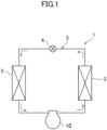
- the refrigerant circuit (2) includes the compressor (10), a radiator (condenser) (3), a decompression mechanism (4), and an evaporator (5).
- the compressor (10), the radiator (3), the decompression mechanism (4), and the evaporator (5) are connected in series by pipes.
- the decompression mechanism (4) is an expansion valve, for example.
- the refrigerant circuit (2) circulates the refrigerant to perform a vapor compression refrigeration cycle.
- the refrigerant compressed by the compressor (10) dissipates heat to air in the radiator (3). At this time, the refrigerant is liquefied. The refrigerant having dissipated heat is decompressed by the decompression mechanism (4). The decompressed refrigerant is evaporated in the evaporator (5). The evaporated refrigerant is sucked into the compressor (10). The compressor (10) compresses the sucked refrigerant.
- the refrigeration apparatus (1) is an air conditioner, for example.
- the air conditioner may be a cooling and heating machine that switches between cooling and heating.
- the air conditioner has a switching mechanism that switches the direction of circulation of the refrigerant.
- the switching mechanism is a four-way switching valve, for example.
- the air conditioner may be a machine dedicated to cooling or a machine dedicated to heating.
- the refrigeration apparatus (1) may be a water heater, a chiller unit, or a cooling apparatus configured to cool air in an internal space.
- the cooling apparatus is for cooling the air inside a refrigerator, a freezer, or a container, for example.
- the compressor (10) is a centrifugal compressor (10).
- the compressor (10) sucks a low-pressure refrigerant and compresses the refrigerant.
- the compressor (10) discharges the compressed high-pressure refrigerant.
- a direction along the axis (X) of a shaft (62) of the compressor (10) will be referred to as an "axial direction,” a direction perpendicular to the axial direction as a radial direction, and a direction along the periphery of the shaft (62) as a "circumferential direction.”
- the maximum number of rotations of the shaft (62) is 30000 rpm or more.
- the maximum number of rotations defines the maximum value of the number of rotations of an electric motor (60). It is preferable to increase the maximum number of rotations of the shaft (62) in the compressor (10) in order to increase the amount of circulation of the refrigerant in the refrigerant circuit (2) and ensure the maximum amount of circulation of the refrigerant. This is advantageous in increasing the cooling capacity in a cooling operation and the heating capacity in a heating operation.
- the compressor (10) includes a casing (20), the electric motor (60), a bearing (70), and an impeller (90).
- the electric motor (60), the bearing (70), and the impeller (90) are housed in the casing (20).
- the casing (20) is a substantially cylindrical hermetic container with both ends closed.
- the casing (20) is placed with its center line extending substantially horizontally.
- the casing (20) extends in the axial direction.
- the casing (20) has an internal space (22).
- the casing (20) has a first wall (24) and a second wall (26).
- the first wall (24) defines the internal space (22) on one side in the axial direction.
- the second wall (26) defines the internal space (22) on the other side in the axial direction.
- Part of the internal space (22) on one side that is outside the first wall (24) in the axial direction constitutes an impeller chamber (28).
- Part of the internal space (22) on the other side that is outside the second wall (26) in the axial direction constitutes a thrust bearing chamber (30).
- An intermediate part of the internal space (22) inward of the first wall (24) and the second wall (26) in the axial direction constitutes an electric motor chamber (32).
- the first wall (24) and the second wall (26) have insertion holes (34, 36), respectively.
- the shaft (62) of the electric motor (60) is inserted in both the insertion holes (34, 36).
- a gap (38) is provided between the inner peripheral surface of the insertion hole (34) of the first wall (24) and the shaft (62).
- the gap (38) forms a radial seal (40).
- the radial seal (40) seals between the first wall (24) and the shaft (62) in the axial direction.
- a diffuser (42) and a scroll flow path (44) are provided at the outer periphery of the impeller chamber (28).
- the diffuser (42) is formed in an annular shape between the impeller chamber (28) and the scroll flow path (44).
- the diffuser (42) is defined by a pair of side surfaces facing each other in the axial direction of the casing (20).
- the diffuser (42) allows the impeller chamber (28) to communicate with the scroll flow path (44).
- the scroll flow path (44) is formed spirally around the diffuser (42).
- the casing (20) is provided with an inlet (46) and an outlet (48).
- the inlet (46) opens at one end of the casing (20) near the impeller chamber (28) in the axial direction.
- the inlet (46) communicates with a center portion of the impeller chamber (28).
- a suction pipe (50) is connected to the inlet (46).
- the outlet (48) is formed at the outer end of the scroll flow path (44).
- the outlet (48) communicates with the scroll flow path (44).
- a discharge pipe (52) is connected to the outlet (48).
- the electric motor (60) is a drive source of the impeller (90).
- the electric motor (60) is housed in the electric motor chamber (32).
- the electric motor (60) is a permanent magnet synchronous motor, for example.
- the electric motor (60) includes the shaft (62), a rotor (64), and a stator (66).
- the electric motor (60) is oriented so that the direction of the axis (X) (axial direction) of the shaft (62) is horizontal.
- the shaft (62) is a rod-shaped member that drives the impeller (90).
- the shaft (62) extends in the internal space (22) in the direction along the center line of the casing (20).
- the shaft (62) is inserted into the insertion holes (34, 36) formed in the first wall (24) and the second wall (26).
- One end portion of the shaft (62) is located in the impeller chamber (28).
- the other end portion of the shaft (62) is located in the thrust bearing chamber (30).
- the rotor (64) is formed in a substantially cylindrical shape.
- the shaft (62) is inserted into the rotor (64).
- the rotor (64) is provided at an intermediate portion of the shaft (62).
- the rotor (64) is fixed to the shaft (62).
- the rotor (64) is disposed substantially coaxially with the shaft (62).
- the rotor (64) is provided with a plurality of permanent magnets.
- the rotor (64) rotates integrally with the shaft (62).
- the stator (66) is formed in a substantially cylindrical shape.
- the stator (66) is disposed to surround the outer periphery of the rotor (64).
- the stator (66) is fixed to the inner wall of the casing (20).
- a coil is wound around the stator (66).
- the inner peripheral surface of the stator (66) faces the outer peripheral surface of the rotor (64) with a predetermined gap (air gap) interposed therebetween in the radial direction.
- the electric motor (60) rotates the shaft (62) by interaction between magnetic flux and current between the rotor (64) and the stator (66).
- a disk (68) is provided at an end portion of the shaft (62) located in the thrust bearing chamber (30).
- the disk (68) is formed in a circular shape extending outward of the shaft (62) in the radial direction.
- the disk (68) is disposed substantially coaxially with the shaft (62).
- the disk (68) is a component of a thrust bearing (74).
- the compressor (10) includes, as the bearing (70), a pair of touchdown bearings (72), the thrust bearing (74), and a pair of radial bearings (80).
- the touchdown bearing (72) is a rolling bearing.
- the touchdown bearing (72) rotatably supports the shaft (62) when the electric motor (60) is not energized.
- the touchdown bearing (72) receives a radial load acting radially outward of the shaft (62).
- the touchdown bearing (72) is attached to the inner wall of the casing (20).
- the touchdown bearings (72) are each provided on the inner peripheral surface of the insertion hole (34) of the first wall (24) and the inner peripheral surface of the insertion hole (36) of the second wall (26).
- One of the touchdown bearings (72) is disposed to surround the outer periphery of a portion of the shaft (62) closer to the impeller chamber (28).
- the other touchdown bearing (72) is disposed to surround the outer periphery of a portion of the shaft (62) closer to the thrust bearing chamber (30).
- the thrust bearing (74) is a magnetic bearing.
- the thrust bearing (74) rotatably supports the disk (68) of the shaft (62) in a non-contact manner by floating the disk (68) by electromagnetic force.
- the thrust bearing (74) receives a thrust load acting in the axial direction of the shaft (62).
- the thrust bearing (74) is attached to the inner wall of the casing (20).
- the thrust bearing (74) is disposed in the thrust bearing chamber (30).
- the thrust bearing (74) includes a pair of electromagnets (76).
- Each of the pair of electromagnets (76) is formed in an annular shape.
- the pair of electromagnets (76) is arranged to face each other with an outer peripheral portion of the disk (68) of the shaft (62) interposed therebetween.
- Each electromagnet (76) is spaced apart from the disk (68).
- the radial bearings (80) are arranged on both sides of the rotor (64) and the stator (66) in the electric motor chamber (32).
- the rotor (64) and the stator (66) divide the electric motor chamber (32) into a first space (32a) and a second space (32b).
- the first space (32a) is a space near the first wall (24).
- the second space (32b) is a space near the second wall (26).
- the radial bearings (80) are each provided in the first space (32a) and the second space (32b).
- Each of the radial bearing (80) is held by a holding member (82).
- the holding member (82) is formed in a substantially circular disk shape.
- the outer peripheral surface of the holding member (82) is fixed to the inner wall of the casing (20).
- a tubular portion (83) is provided at a center portion of the holding member (82).
- the tubular portion (83) has an insertion hole (84) penetrating the holding member (82).
- the shaft (62) is inserted into the insertion hole (84).
- the radial bearing (80) is housed inside the insertion hole (84).
- the radial bearing (80) supports the shaft (62) at the outer periphery of the shaft (62). As illustrated in FIG. 4 , the radial bearing (80) is a foil bearing.
- the radial bearing (80) rotatably supports the shaft (62) in a non-contact manner by forming a gas film (GF) between the radial bearing (80) and the shaft (62) and floating the shaft (62) by the gas film (GF).
- the radial bearing (80) receives a radial load acting radially outward of the shaft (62).
- the radial bearing (80) includes a bearing housing (86), a top foil (88), and a back foil (89).
- the bearing housing (86) is formed in a cylindrical shape.
- the bearing housing (86) has an insertion hole (87).
- the shaft (62) is inserted into a center portion of the insertion hole (87).
- the top foil (88) and the back foil (89) are housed in the insertion hole (87) at the outer periphery of the shaft (62).
- the back foil (89) is located on the inner peripheral surface side of the insertion hole (87).
- the top foil (88) is located on the center side (closer to the shaft (62)) of the insertion hole (87).
- the top foil (88) is formed in a cylindrical shape.
- the inner peripheral surface of the top foil (88) faces the outer peripheral surface of the shaft (62), and forms a bearing surface.
- the top foil (88) is a thin metal plate and is flexible. One end portion of the top foil (88) in the circumferential direction is bent to the outer peripheral side and joined to the back foil (89). Thus, the top foil (88) is fixed to the back foil (89).
- the back foil (89) is formed in a cylindrical shape.
- the back foil (89) is disposed between the bearing housing (86) and the top foil (88).
- the back foil (89) is fixed to the bearing housing (86).
- the back foil (89) elastically supports the top foil (88).
- the back foil (89) is a bump foil, for example.
- the back foil (89) may be a mesh foil.
- the impeller (90) When the impeller (90) rotates, the refrigerant sucked into the impeller chamber (28) is compressed by a centrifugal force.
- the refrigerant compressed in the impeller chamber (28) flows through the scroll flow path (44) by way of the diffuser (42).
- the refrigerant having flowed through the scroll flow path (44) is discharged to the discharge pipe (52) through the outlet (48).
- the rotation of the impeller (90) increases the pressure in the impeller chamber (28). At this time, the air pressure in the impeller chamber (28) is relatively high, and the air pressure in the electric motor chamber (32) is relatively low.
- the specific speed Ns of the impeller (90) is set to be less than 0.1.
- a specific speed of a dimensionless number is used as the specific speed Ns.
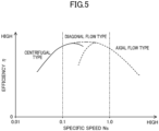
- the efficiency of the centrifugal type impeller (90) decreases as the specific speed Ns decreases.
- the number of rotations N may be increased, so that the specific speed Ns of the impeller (90) can be increased.
- the impeller (90) is designed to have a low specific speed Ns, which is less than 0.1.
- the diameter D of the impeller (90) In order to increase the head H with the impeller (90) designed to have such a low specific speed, the diameter D of the impeller (90) needs to be increased.
- the magnitude of the head H is proportional to the integrated value of the number of rotations N and the diameter D of the impeller (90) (H ⁇ N ⁇ D). If the compressor (10) has the same capacity and the same head in design, the greater the diameter D of the impeller (90), the greater the windage loss W of the impeller (90).
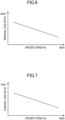
- the smaller the specific speed Ns the higher the ratio of the windage loss W of the impeller (90) to the mechanical loss of the compressor (10).
- C is a windage loss coefficient.
- the windage loss coefficient C is determined based on, for example, the material and structure of the impeller (90) and the frictional resistance of the impeller (90) with gas. Any of a design value, an analysis value, and an actual measurement value may be used as the windage loss coefficient C.
- ⁇ is a fluid density [kg/m 3 ].
- N is the number of rotations [s -1 ].
- D is the diameter [mm] of the impeller (90).
- the leakage loss of the compressor (10) is a loss due to leakage of gas from the impeller chamber (28).
- the leakage loss increases in accordance with the amount of gas leakage.
- the amount of gas leakage is determined by a pressure difference between the impeller chamber (28) and the outside of the impeller chamber (28). If the compressor (10) of the same head design is configured to have a smaller capacity, the mass flow rate of a main flow decreases without a change in the pressure difference between the impeller chamber (28) and the outside of the impeller chamber (28). Accordingly, the ratio of the leakage amount increases, and the leakage loss of the compressor (10) increases.
- the smaller the specific speed Ns of the impeller (90) the higher the ratio of the leakage loss to the mechanical loss of the compressor (10).
- the ratio of the windage loss W and leakage loss of the impeller (90) to the mechanical loss is high in the compressor (10) using the impeller (90) designed to have a low specific speed.
- the back gap (92) on the back surface (91) of the impeller (90) is designed to improve the sealability between the rotary unit (100) and the first wall (24) while reducing an increase in the windage loss W of the impeller (90).
- the width of the back gap (92) in the axial direction of the shaft (62) is referred to as an axial width s, and a structure in which the axial width s of the back gap (92) differs between the inner peripheral side and the outer peripheral side is employed.
- a relatively greater axial width s of the back gap (92) is ensured on the outer peripheral side where the rotational speed of the impeller (90) is high, to reduce the windage loss W, and the inner peripheral side is used as a seal.
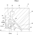
- a recess (93) is formed in the surface of the first wall (24) facing the impeller chamber (28).
- the recess (93) is an annular groove recessed toward the electric motor chamber (32).
- the recess (93) is provided at a position corresponding to the outer peripheral side of the impeller (90).
- the axial width s of the back gap (92) differs between a portion corresponding to the recess (93) and a portion where there is no recess (93).
- the back gap (92) includes a first gap (94) and a second gap (96).
- the first gap (94) is the back gap (92) at the portion where there is no recess (93).
- the second gap (96) is the back gap (92) at the portion corresponding to the recess (93).
- the first gap (94) is provided at a position corresponding to the inner peripheral side of the impeller (90).
- the first gap (94) is formed in an annular shape between the first wall (24) on the inner peripheral side of the recess (93) and the back surface (91) of the impeller (90).
- the axial width s1 of the first gap (94) is relatively small in the back gap (92).
- the first gap (94) forms an axial seal (95).
- the axial seal (95) seals between the back surface (91) of the impeller (90) and the first wall (24) in the radial direction.
- the axial seal (95) and the radial seal (40) together reduce leakage of gas handled by the compressor (10) from the impeller chamber (28) into the electric motor chamber (32) through the insertion hole (34) of the first wall (24).
- the first gap (94) extends in the direction perpendicular to the axis (X) of the shaft (62), i.e., in the radial direction, so as to be flat.
- the back surface (91) of the impeller (90) and the first wall (24) face each other in the axial direction with the first gap (94) therebetween.
- the second gap (96) is provided at a position corresponding to the outer peripheral side of the impeller (90).
- the second gap (96) is formed in an annular shape between the back surface (91) of the impeller (90) and the bottom of the recess (93).
- the axial width s2 of the second gap (96) is relatively great in the back gap (96). That is, the axial width s2 of the second gap (96) is greater than the axial width s1 of the first gap (94).
- the ratio (s/r) of the axial width s of the back gap (92) to the impeller radius r, which is the radius of the impeller (90) satisfies a relationship of 0.008 ⁇ s/r ⁇ 0.5 in the second gap (96).
- the ratio (s2/r) of the axial width s2 of the second gap (96) to the impeller radius r is set to be 0.008 or more and 0.5 or less. If the ratio (s2/r) is less than 0.008, the windage loss W of the impeller (90) is relatively great. On the other hand, even if the ratio (s2/r) is greater than 0.5, a further increase in the effect of reducing the windage loss W of the impeller (90) cannot be expected as compared with a case where the ratio (s2/r) is 0.5 or less. From these facts, the ratio (s2/r) of the axial width s2 of the second gap (96) to the impeller radius r is set to satisfy the above-described relationship.
- the ratio (s2/r) of the axial width s2 of the second gap (96) to the impeller radius r is preferably 0.02 or more. This is advantageous in reducing the windage loss W of the impeller (90). From the same point of view, the ratio (s2/r) of the axial width s2 of the second gap (96) to the impeller radius r is more preferably 0.06 or more. The ratio (s2/r) is much more preferably 0.1 or more. From the above point of view, the ratio (s2/r) is desirably 0.125 or more.
- a relationship (function indicating a curve) between the ratio (s/r) of the gap (s) in the axial direction of a circular disk to the radius (r) of the circular disk (hereinafter, referred to as a radius gap ratio) and a friction loss coefficient when the circular disk is rotated is known.
- the higher the friction loss coefficient of the circular disk the greater the energy loss associated with the rotation of the circular disk.
- Such a relationship is obtained for each Reynolds number Re, and as indicated by a dash-dot line in FIG. 8 , there is a tendency that the higher the Reynolds number Re, the smaller the radius gap ratio at which the friction loss coefficient of the circular disk is the minimum value.
- Prior Document 1 The above relationship between the radius gap ratio of the circular disk and the friction loss coefficient is described in Prior Document 1 below.
- a test method for obtaining the relationship is described in Prior Document 2 below.
- the inventor(s) of the present application newly conducted a test for a case where a refrigerant gas was the cause of friction, to obtain the relationship between the radius gap ratio (s/r) of the circular disk and the friction loss coefficient (windage loss coefficient).
- An indirect measurement method was performed as the test, in which a circular disk was rotatably housed in a cylindrical casing and was rotated to free-run with the casing filled with the refrigerant gas, to measure a degree of reduction of the number of rotations and calculate the friction loss coefficient (windage loss coefficient) of the circular disk from the degree of the reduction.
- the refrigerant gas used in this test was R32 with a Reynolds number Re of 10 7 .
- a circular disk having a diameter of 40 mm was used as the circular disk.
- the number of free-run rotations of the circular disk was set to be 55000 rpm and 75000 rpm, and the degree of reduction from each number of rotations was measured.
- the gap (s) between the circular disk and the casing in the axial direction was adjusted to three points at which the radius gap ratio (s/r) was 0.008, 0.02, and 0.125, and the friction loss coefficient of the circular disk was obtained at these three points.
- the friction loss coefficient was the minimum value when the radius gap ratio (s/r) of the circular disk was around 0.008; however, in a case where the refrigerant gas (R32) was the cause of friction, the minimum value of the friction loss coefficient was present on the side where the radius gap ratio (s/r) of the circular disk was greater than 0.008 and even on the side where the radius gap ratio (s/r) was greater than 0.125.
- the specific speed Ns of the impeller (90) is set to be less than 0.1.
- the impeller (90) designed to have such a low specific speed is advantageous in achieving a small capacity and high-head performance.
- the ratio (s/r) of the axial width s of the second gap (96) in the back gap (92) to the impeller radius r is 0.008 or more and 0.5 or less in the second gap (96).
- the second gap (96) which the back surface (91) of the impeller (90) faces, can have an appropriate axial width s in accordance with the impeller radius r.
- the windage loss W at the back surface (91) of the impeller (90) can thus be reduced.
- the first gap (94) corresponding to the inner peripheral side of the back surface (91) of the impeller (90) forms the axial seal (95).
- the axial seal (95) seals between the back surface (91) of the impeller (90) and the first wall (24). It is thus possible to reduce leakage of the gas handled by the compressor (10) from between the inner peripheral surface of the insertion hole (34) provided in the first wall (24) and the shaft (62) through the back gap (92) on the back side of the impeller (90). Thus, the loss (leakage loss) due to the leakage of the gas in the compressor (10) can be reduced.
- the axial width s2 of the second gap (96) corresponding to the outer peripheral side of the back surface (91) of the impeller (90) is greater than the axial width s1 of the first gap (94).
- the ratio (s2/r) of the axial width s2 of the second gap (96) to the impeller radius r is 0.008 or more and 0.5 or less.
- the rotational speed is higher and the windage loss W at the back surface (91) of the impeller (90) is greater on the outer peripheral side of the impeller (90) than on the inner peripheral side.
- the windage loss W at the back surface (91) of the impeller (90) can be effectively reduced.
- the first gap (94) extends in the direction perpendicular to the axis (X) of the shaft (62) so as to be flat.
- the back surface (91) of the impeller (90) does not come into contact with the first wall (24), and the first gap (94) does not become narrow. Consequently, the reliability of the compressor (10) can be enhanced, and an increase in the windage loss W at the back surface (91) of the impeller (90) can be reduced even under the transient condition.
- the radial bearing (80) supporting the shaft (62) is a foil bearing.
- the radial bearing (80) rotatably supports the shaft (62) in a non-contact manner by forming a gas film (GF) between the radial bearing (80) and the shaft (62) and floating the shaft (62) by the gas film (GF).
- the radial bearing (80) is advantageous in reducing frictional heat generated by rotation of the shaft (62) and the amount of wear of the bearing (80).
- the configuration of the first gap (94) extending in the radial direction so as to be flat is effective because the first gap (94) is prevented from becoming narrow even when the impeller (90) is displaced in the radial direction as described above.
- the maximum number of rotations of the shaft (62) is 30000 rpm or more, which is relatively high.
- Ns the maximum number of rotations of the shaft (62)
- the maximum number of rotations of the shaft (62) that is relatively high is suitable for achieving a small capacity and high-head performance of the compressor (10).
- the refrigerant pumped by the impeller (90) is an HFC refrigerant, an HFO refrigerant, a natural refrigerant, or a refrigerant mixture thereof.
- These refrigerants have a relatively high gas density.
- the windage loss W at the back surface (91) of the impeller (90) increases in proportion to the gas density of the refrigerant handled by the compressor (10).
- the technique of the present disclosure is effective in the compressor (10) which handles the HFC refrigerant, the HFO refrigerant, the natural refrigerant, or the refrigerant mixture thereof.
- the above-described compressor (10) is used in the refrigerant circuit (2). This contributes to the greater efficiency of the refrigeration cycle in the refrigeration apparatus (1).
- a compressor (10) of a first variation is provided with two first gaps (94) and two second gaps (96) as the back gap (92).
- the present disclosure is useful for a centrifugal compressor and a refrigeration apparatus.
Landscapes
- Engineering & Computer Science (AREA)
- Mechanical Engineering (AREA)
- General Engineering & Computer Science (AREA)
- Physics & Mathematics (AREA)
- Thermal Sciences (AREA)
- Electromagnetism (AREA)
- Structures Of Non-Positive Displacement Pumps (AREA)
Abstract
Description
- The present disclosure relates to a centrifugal compressor and a refrigeration apparatus.
- A centrifugal compressor that compresses a fluid using a centrifugal force generated by the rotation of an impeller has been known. In the centrifugal compressor, a leakage loss occurs when part of the fluid pumped by the impeller leaks from the back side of the impeller to a space in which a motor is disposed. In order to reduce the leakage loss, various seal structures have been proposed for the centrifugal compressor. One example of such a seal structure is disclosed in Patent Document 1.
- Patent Document 1:
Japanese Unexamined Patent Publication No. 2014-231827 - In the conventional centrifugal compressor, the impeller is designed to have a relatively high specific speed; therefore, the ratio of a windage loss, caused by friction with gas on the back surface of the impeller, to a mechanical loss is small. Thus, no improvement has been made on the windage loss at the back surface of the impeller. However, in a case where the impeller is designed to have a relatively low specific speed, the ratio of the windage loss at the back surface of the impeller to the mechanical loss increases. Thus, the influence of the windage loss at the back surface of the impeller on the compression efficiency cannot be ignored.
- It is an object of the present disclosure to enhance the compression efficiency of a centrifugal compressor designed to have a low specific speed.
- A first aspect of the present disclosure is directed to a centrifugal compressor (10). The centrifugal compressor (10) of the first aspect includes: a casing (20); an impeller (90) housed in the casing (20); and a shaft (62) coupled to the impeller (90). The casing (20) has a wall (24) facing the back surface (91) of the impeller (90). The shaft (62) is inserted into an insertion hole (34) formed in the wall (24). A back gap (92) is formed between the back surface (91) of the impeller (90) and the wall (24). A specific speed of the impeller (90) is set to be less than 0.1. A ratio of an axial width s of the back gap (92) to an impeller radius r satisfies a relationship of 0.008 ≤ s/r ≤ 0.5, where the axial width s is a width of the back gap (92) in an axial direction of the shaft (62), and the impeller radius r is a radius of the impeller (90).
- According to the first aspect, the specific speed of the impeller (90) is set to be less than 0.1. The impeller (90) designed to have such a low specific speed is advantageous in achieving a small capacity and high-head performance. In this centrifugal compressor (10), the ratio (s/r) of the axial width s of the back gap (92) to the impeller radius r is 0.008 or more and 0.5 or less. Thus, the back gap (92), which the back surface (91) of the impeller (90) faces, can have an appropriate axial width s in accordance with the impeller radius r. The windage loss at the back surface (91) of the impeller (90) can thus be reduced. As a result, it is possible to enhance the compression efficiency of the centrifugal compressor (10) designed to have a low specific speed.
- A second aspect of the present disclosure is an embodiment of the centrifugal compressor (10) of the first aspect. In the second aspect, the back gap (92) includes a first gap (94) corresponding to an inner peripheral side of the back surface (91) of the impeller (90), the first gap (94) forming a seal (95) that seals between the back surface (91) of the impeller (90) and the wall (24). The back gap (92) includes a second gap (96) corresponding to an outer peripheral side of the back surface of the impeller (90), and the axial width s of the second gap (96) is greater than the axial width of the first gap (94) and satisfies the relationship of the ratio (s/r) to the impeller radius r.
- According to the second aspect, the first gap (94) corresponding to the inner peripheral side of the back surface (91) of the impeller (90) forms the seal (95). The seal (95) seals between the back surface (91) of the impeller (90) and the wall (24) of the casing (20). It is thus possible to reduce leakage of the gas handled by the centrifugal compressor (10) from between the inner peripheral surface of the insertion hole (34) provided in the wall (24) and the shaft (62) through the back gap (92) on the back side of the impeller (90). Thus, the loss (leakage loss) due to the leakage of the gas in the centrifugal compressor (10) can be reduced.
- According to the second aspect, the axial width s of the second gap (96) corresponding to the outer peripheral side of the back surface (91) of the impeller (90) is greater than the axial width s of the first gap (94). The ratio (s/r) of the axial width s of the second gap (96) to the impeller radius r is 0.008 or more and 0.5 or less. The rotational speed is higher and the windage loss at the back surface (91) of the impeller (90) is greater on the outer peripheral side of the impeller (90) than on the inner peripheral side. Thus, the windage loss at the back surface (91) of the impeller (90) can be effectively reduced.
- A third aspect of the present disclosure is an embodiment of the centrifugal compressor (10) of the second aspect. In the third aspect, the first gap (94) extends in a direction perpendicular to an axis (X) of the shaft (62) so as to be flat.
- According to the third aspect, the first gap (94) extends in the direction perpendicular to the axis (X) of the shaft (62) so as to be flat. The back surface (91) of the impeller (90) and the wall (24) of the casing (20), which form the first gap (94), face each other in the axial direction along the axis (X) of the shaft (62). Under the transient condition of the centrifugal compressor (10), a radial force may act on the shaft (62), causing the impeller (90) to be displaced in the radial direction together with the shaft (62). When the back surface (91) of the impeller (90) and the wall (24) of the casing (20) face each other in the axial direction along the axis (X) of the shaft (62), the back surface (91) of the impeller (90) and the wall (24), which form the first gap (94), do not come into contact with each other and the first gap (94) does not become narrow even when the impeller (90) is displaced in the radial direction together with the shaft (62). Consequently, the reliability of the centrifugal compressor (10) can be enhanced, and an increase in the windage loss at the back surface (91) of the impeller (90) can be reduced even under the transient condition.
- A fourth aspect of the present disclosure is an embodiment of the centrifugal compressor (10) of any one of the first to third aspects. In the fourth aspect, the centrifugal compressor (10) further includes a radial bearing (80) supporting the shaft (62) at the outer periphery of the shaft (62). The radial bearing (80) is a foil bearing or a magnetic bearing.
- According to the fourth aspect, the radial bearing (80) supporting the shaft (62) at the outer periphery of the shaft (62) is a foil bearing or a magnetic bearing. The foil bearing rotatably supports the shaft (62) in a non-contact manner by forming a gas film (GF) between the foil bearing and the shaft (62) and floating the shaft (62) by the gas film (GF). The magnetic bearing rotatably supports the shaft (62) in a non-contact manner by floating the shaft (62) by magnetic force. The foil bearing and the magnetic bearing are advantageous in reducing frictional heat generated by rotation of the shaft (62) and the amount of wear of the radial bearing (80). In the centrifugal compressor (10) using the foil bearing or the magnetic bearing as the radial bearing (80), displacement of the shaft (62) in the radial direction under the transient condition is relatively great. Thus, the configuration of the third aspect is effective for such a centrifugal compressor (10).
- A fifth aspect of the present disclosure is an embodiment of the centrifugal compressor (10) of any one of the first to fourth aspects. In the fifth aspect, a maximum number of rotations of the shaft (62) is 30000 rpm or more.
- According to the fifth aspect, the maximum number of rotations of the shaft (62) is 30000 rpm or more, which is relatively high. When the centrifugal compressor (10) is operated at a predetermined specific speed, it is possible to reduce the capacity of the centrifugal compressor (10) or increase the head of the centrifugal compressor (10) as the maximum number of rotations of the shaft (62) increases. Thus, the maximum number of rotations of the shaft (62) that is relatively high is suitable for achieving a small capacity and high-head performance of the centrifugal compressor (10).
- A sixth aspect of the present disclosure is an embodiment of the centrifugal compressor (10) of any one of the first to fifth aspects. In the sixth aspect, the impeller (90) pumps a refrigerant. The refrigerant is an HFC refrigerant, an HFO refrigerant, a natural refrigerant, or a refrigerant mixture thereof.
- According to the sixth aspect, the refrigerant pumped by the impeller (90) is an HFC refrigerant, an HFO refrigerant, a natural refrigerant, or a refrigerant mixture thereof. These refrigerants have a relatively high gas density. The windage loss at the back surface (91) of the impeller (90) increases in proportion to the gas density of the refrigerant handled by the centrifugal compressor (10). Thus, the technique of the present disclosure is effective in the centrifugal compressor which handles the HFC refrigerant, the HFO refrigerant, the natural refrigerant, or the refrigerant mixture thereof.
- A seventh aspect of the present disclosure is directed to a refrigeration apparatus (1). The refrigeration apparatus (1) of the seventh aspect includes a refrigerant circuit (2) configured to perform a refrigeration cycle. The refrigerant circuit (2) includes the centrifugal compressor (10) of any one of the first to sixth aspects.
- According to the seventh aspect, the above-described centrifugal compressor (10) is used in the refrigerant circuit (2). This contributes to the greater efficiency of the refrigeration cycle in the refrigeration apparatus (1).
-
-
FIG. 1 is a schematic configuration diagram of a refrigerant circuit in a refrigeration apparatus of an embodiment. -
FIG. 2 is a sectional view illustrating, as an example, a schematic configuration of a centrifugal compressor of the embodiment. -
FIG. 3 is a sectional view illustrating, as an example, a main portion of the centrifugal compressor of the embodiment. -
FIG. 4 is a cross-sectional view illustrating, as an example, a schematic configuration of a bearing for use in the centrifugal compressor of the embodiment. -
FIG. 5 is a graph schematically showing a relationship between the efficiency and the specific speed of each of centrifugal type, diagonal flow type, and axial flow type impellers. -
FIG. 6 is a graph schematically showing a relationship between the specific speed and the windage loss ratio of the impeller. -
FIG. 7 is a graph schematically showing a relationship between the specific speed and the leakage loss ratio of the impeller. -
FIG. 8 is a graph showing a relationship between the ratio of a gap to the radius of a circular disk and a friction loss coefficient. -
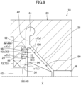
FIG. 9 is a sectional view illustrating, as an example, a main portion of a centrifugal compressor of a first variation. -
FIG. 10 is a sectional view illustrating, as an example, a main portion of a centrifugal compressor of a second variation. -
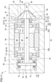
FIG. 11 is a sectional view illustrating, as an example, a schematic configuration of a centrifugal compressor of a fourth variation. -
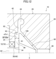
FIG. 12 is a sectional view illustrating, as an example, a main portion of a centrifugal compressor of another embodiment. - Illustrative embodiments will be described below in detail with reference to the drawings. In the following embodiment, a case in which a compressor according to the technology of the present disclosure is applied to a refrigeration apparatus will be described as an example. The drawings are used for conceptual description of the technology of the present disclosure. In the drawings, dimensions, ratios, or numbers may be exaggerated or simplified for easier understanding of the technique of the present disclosure.
- A compressor (10) according to this embodiment is provided in a refrigeration apparatus (1).
- As illustrated in
FIG. 1 , the refrigeration apparatus (1) includes a refrigerant circuit (2). The refrigerant circuit (2) is filled with a refrigerant. A fluid compressed by the compressor (10) of this example is a refrigerant. For example, the refrigerant is a hydro fluoro carbon (HFC) refrigerant such as R32, a hydro fluoro olefin (HFO) refrigerant such as R1234yf, a natural refrigerant, or a refrigerant mixture thereof such as R454C (a refrigerant mixture of R32 and R1234yf). Examples of the natural refrigerant include a natural refrigerant containing HC, such as propane. - The refrigerant circuit (2) includes the compressor (10), a radiator (condenser) (3), a decompression mechanism (4), and an evaporator (5). The compressor (10), the radiator (3), the decompression mechanism (4), and the evaporator (5) are connected in series by pipes. The decompression mechanism (4) is an expansion valve, for example. The refrigerant circuit (2) circulates the refrigerant to perform a vapor compression refrigeration cycle.
- In the refrigeration cycle, the refrigerant compressed by the compressor (10) dissipates heat to air in the radiator (3). At this time, the refrigerant is liquefied. The refrigerant having dissipated heat is decompressed by the decompression mechanism (4). The decompressed refrigerant is evaporated in the evaporator (5). The evaporated refrigerant is sucked into the compressor (10). The compressor (10) compresses the sucked refrigerant.
- The refrigeration apparatus (1) is an air conditioner, for example. The air conditioner may be a cooling and heating machine that switches between cooling and heating. In this case, the air conditioner has a switching mechanism that switches the direction of circulation of the refrigerant. The switching mechanism is a four-way switching valve, for example. The air conditioner may be a machine dedicated to cooling or a machine dedicated to heating.
- The refrigeration apparatus (1) may be a water heater, a chiller unit, or a cooling apparatus configured to cool air in an internal space. The cooling apparatus is for cooling the air inside a refrigerator, a freezer, or a container, for example.
- The compressor (10) is a centrifugal compressor (10). The compressor (10) sucks a low-pressure refrigerant and compresses the refrigerant. The compressor (10) discharges the compressed high-pressure refrigerant. In the following description, a direction along the axis (X) of a shaft (62) of the compressor (10) will be referred to as an "axial direction," a direction perpendicular to the axial direction as a radial direction, and a direction along the periphery of the shaft (62) as a "circumferential direction."
- In the compressor (10), the maximum number of rotations of the shaft (62) is 30000 rpm or more. The maximum number of rotations defines the maximum value of the number of rotations of an electric motor (60). It is preferable to increase the maximum number of rotations of the shaft (62) in the compressor (10) in order to increase the amount of circulation of the refrigerant in the refrigerant circuit (2) and ensure the maximum amount of circulation of the refrigerant. This is advantageous in increasing the cooling capacity in a cooling operation and the heating capacity in a heating operation.
- As illustrated in
FIG. 2 , the compressor (10) includes a casing (20), the electric motor (60), a bearing (70), and an impeller (90). The electric motor (60), the bearing (70), and the impeller (90) are housed in the casing (20). - The casing (20) is a substantially cylindrical hermetic container with both ends closed. The casing (20) is placed with its center line extending substantially horizontally. The casing (20) extends in the axial direction. The casing (20) has an internal space (22). The casing (20) has a first wall (24) and a second wall (26). The first wall (24) defines the internal space (22) on one side in the axial direction. The second wall (26) defines the internal space (22) on the other side in the axial direction.
- Part of the internal space (22) on one side that is outside the first wall (24) in the axial direction constitutes an impeller chamber (28). Part of the internal space (22) on the other side that is outside the second wall (26) in the axial direction constitutes a thrust bearing chamber (30). An intermediate part of the internal space (22) inward of the first wall (24) and the second wall (26) in the axial direction constitutes an electric motor chamber (32).
- The first wall (24) and the second wall (26) have insertion holes (34, 36), respectively. The shaft (62) of the electric motor (60) is inserted in both the insertion holes (34, 36). A gap (38) is provided between the inner peripheral surface of the insertion hole (34) of the first wall (24) and the shaft (62). The gap (38) forms a radial seal (40). The radial seal (40) seals between the first wall (24) and the shaft (62) in the axial direction.
- In the casing (20), a diffuser (42) and a scroll flow path (44) are provided at the outer periphery of the impeller chamber (28). The diffuser (42) is formed in an annular shape between the impeller chamber (28) and the scroll flow path (44). The diffuser (42) is defined by a pair of side surfaces facing each other in the axial direction of the casing (20). The diffuser (42) allows the impeller chamber (28) to communicate with the scroll flow path (44). The scroll flow path (44) is formed spirally around the diffuser (42).
- The casing (20) is provided with an inlet (46) and an outlet (48). The inlet (46) opens at one end of the casing (20) near the impeller chamber (28) in the axial direction. The inlet (46) communicates with a center portion of the impeller chamber (28). A suction pipe (50) is connected to the inlet (46). The outlet (48) is formed at the outer end of the scroll flow path (44). The outlet (48) communicates with the scroll flow path (44). A discharge pipe (52) is connected to the outlet (48).
- The electric motor (60) is a drive source of the impeller (90). The electric motor (60) is housed in the electric motor chamber (32). The electric motor (60) is a permanent magnet synchronous motor, for example. The electric motor (60) includes the shaft (62), a rotor (64), and a stator (66). The electric motor (60) is oriented so that the direction of the axis (X) (axial direction) of the shaft (62) is horizontal.
- The shaft (62) is a rod-shaped member that drives the impeller (90). The shaft (62) extends in the internal space (22) in the direction along the center line of the casing (20). The shaft (62) is inserted into the insertion holes (34, 36) formed in the first wall (24) and the second wall (26). One end portion of the shaft (62) is located in the impeller chamber (28). The other end portion of the shaft (62) is located in the thrust bearing chamber (30).
- The rotor (64) is formed in a substantially cylindrical shape. The shaft (62) is inserted into the rotor (64). The rotor (64) is provided at an intermediate portion of the shaft (62). The rotor (64) is fixed to the shaft (62). The rotor (64) is disposed substantially coaxially with the shaft (62). The rotor (64) is provided with a plurality of permanent magnets. The rotor (64) rotates integrally with the shaft (62).
- The stator (66) is formed in a substantially cylindrical shape. The stator (66) is disposed to surround the outer periphery of the rotor (64). The stator (66) is fixed to the inner wall of the casing (20). A coil is wound around the stator (66). The inner peripheral surface of the stator (66) faces the outer peripheral surface of the rotor (64) with a predetermined gap (air gap) interposed therebetween in the radial direction.
- The electric motor (60) rotates the shaft (62) by interaction between magnetic flux and current between the rotor (64) and the stator (66). A disk (68) is provided at an end portion of the shaft (62) located in the thrust bearing chamber (30). The disk (68) is formed in a circular shape extending outward of the shaft (62) in the radial direction. The disk (68) is disposed substantially coaxially with the shaft (62). The disk (68) is a component of a thrust bearing (74).
- The compressor (10) includes, as the bearing (70), a pair of touchdown bearings (72), the thrust bearing (74), and a pair of radial bearings (80).
- The touchdown bearing (72) is a rolling bearing. The touchdown bearing (72) rotatably supports the shaft (62) when the electric motor (60) is not energized. The touchdown bearing (72) receives a radial load acting radially outward of the shaft (62). The touchdown bearing (72) is attached to the inner wall of the casing (20).
- The touchdown bearings (72) are each provided on the inner peripheral surface of the insertion hole (34) of the first wall (24) and the inner peripheral surface of the insertion hole (36) of the second wall (26). One of the touchdown bearings (72) is disposed to surround the outer periphery of a portion of the shaft (62) closer to the impeller chamber (28). The other touchdown bearing (72) is disposed to surround the outer periphery of a portion of the shaft (62) closer to the thrust bearing chamber (30).
- The thrust bearing (74) is a magnetic bearing. The thrust bearing (74) rotatably supports the disk (68) of the shaft (62) in a non-contact manner by floating the disk (68) by electromagnetic force. The thrust bearing (74) receives a thrust load acting in the axial direction of the shaft (62). The thrust bearing (74) is attached to the inner wall of the casing (20).
- The thrust bearing (74) is disposed in the thrust bearing chamber (30). The thrust bearing (74) includes a pair of electromagnets (76). Each of the pair of electromagnets (76) is formed in an annular shape. The pair of electromagnets (76) is arranged to face each other with an outer peripheral portion of the disk (68) of the shaft (62) interposed therebetween. Each electromagnet (76) is spaced apart from the disk (68).
- The radial bearings (80) are arranged on both sides of the rotor (64) and the stator (66) in the electric motor chamber (32). The rotor (64) and the stator (66) divide the electric motor chamber (32) into a first space (32a) and a second space (32b). The first space (32a) is a space near the first wall (24). The second space (32b) is a space near the second wall (26). The radial bearings (80) are each provided in the first space (32a) and the second space (32b).
- Each of the radial bearing (80) is held by a holding member (82). The holding member (82) is formed in a substantially circular disk shape. The outer peripheral surface of the holding member (82) is fixed to the inner wall of the casing (20). A tubular portion (83) is provided at a center portion of the holding member (82). The tubular portion (83) has an insertion hole (84) penetrating the holding member (82). The shaft (62) is inserted into the insertion hole (84). The radial bearing (80) is housed inside the insertion hole (84).
- The radial bearing (80) supports the shaft (62) at the outer periphery of the shaft (62). As illustrated in
FIG. 4 , the radial bearing (80) is a foil bearing. The radial bearing (80) rotatably supports the shaft (62) in a non-contact manner by forming a gas film (GF) between the radial bearing (80) and the shaft (62) and floating the shaft (62) by the gas film (GF). The radial bearing (80) receives a radial load acting radially outward of the shaft (62). The radial bearing (80) includes a bearing housing (86), a top foil (88), and a back foil (89). - The bearing housing (86) is formed in a cylindrical shape. The bearing housing (86) has an insertion hole (87). The shaft (62) is inserted into a center portion of the insertion hole (87). The top foil (88) and the back foil (89) are housed in the insertion hole (87) at the outer periphery of the shaft (62). The back foil (89) is located on the inner peripheral surface side of the insertion hole (87). The top foil (88) is located on the center side (closer to the shaft (62)) of the insertion hole (87).
- The top foil (88) is formed in a cylindrical shape. The inner peripheral surface of the top foil (88) faces the outer peripheral surface of the shaft (62), and forms a bearing surface. The top foil (88) is a thin metal plate and is flexible. One end portion of the top foil (88) in the circumferential direction is bent to the outer peripheral side and joined to the back foil (89). Thus, the top foil (88) is fixed to the back foil (89).
- The back foil (89) is formed in a cylindrical shape. The back foil (89) is disposed between the bearing housing (86) and the top foil (88). The back foil (89) is fixed to the bearing housing (86). The back foil (89) elastically supports the top foil (88). The back foil (89) is a bump foil, for example. The back foil (89) may be a mesh foil.
- A predetermined gap (G) is set between the top foil (88) and the shaft (62). When the shaft (62) rotates, the gap (G) is formed between the inner peripheral surface of the top foil (88) and the shaft (62), and gas is drawn into the gap (G) between the top foil (88) and the shaft (62) to form the gas film (GF). The gas film (GF) floats the shaft (62) from the top foil (88). Thus, the radial bearing (80) supports the shaft (62) in a non-contact manner.
- The impeller (90) is housed in the impeller chamber (28). One end portion of the shaft (62) is coupled to the impeller (90). The impeller (90) is formed in a substantially conical shape. The impeller (90) has a plurality of blades. The first wall (24) faces the back surface (91) of the impeller (90). A back gap (92) is formed between the back surface (91) of the impeller (90) and the first wall (24) (see
FIG. 3 ). The back gap (92) is formed in an annular shape. The impeller (90) and the shaft (62) together form a rotary unit (100). The impeller (90) rotates integrally with the shaft (62) to pump the refrigerant. - When the impeller (90) rotates, the refrigerant sucked into the impeller chamber (28) is compressed by a centrifugal force. The refrigerant compressed in the impeller chamber (28) flows through the scroll flow path (44) by way of the diffuser (42). The refrigerant having flowed through the scroll flow path (44) is discharged to the discharge pipe (52) through the outlet (48). The rotation of the impeller (90) increases the pressure in the impeller chamber (28). At this time, the air pressure in the impeller chamber (28) is relatively high, and the air pressure in the electric motor chamber (32) is relatively low.
- The specific speed Ns of the impeller (90) is set to be less than 0.1. As the specific speed Ns, a specific speed of a dimensionless number is used. The specific speed Ns is calculated based on Expression (1) below.
[Mathematical Expression 1]
- Here, "N" is the number of rotations [s-1]. "G" is a fluid mass flow rate [kg/s]. "ρ" is a fluid density [kg/m3]. "gH" is an effective specific work [J/kg]. "g" is a gravitational acceleration [m/s2]. "H" is a head (lifting height) [m].
- As shown in
FIG. 5 , values of the specific speed Ns are roughly determined by the structural type of the impeller (90), such as a centrifugal type, a diagonal flow type, and an axial flow type. Values of the efficiency which can be achieved in accordance with the values of the specific speed Ns are also known empirically. The centrifugal type impeller (90) is advantageous in the efficiency at a low specific speed, as compared with the diagonal flow type impeller and the axial flow type impeller. The centrifugal type impeller (90) exhibits the highest efficiency when the specific speed Ns is in a range of higher than 0.1. - If the specific speed Ns is less than 0.1, the efficiency of the centrifugal type impeller (90) decreases as the specific speed Ns decreases. To design a small capacity and high-head compressor (10), the number of rotations N may be increased, so that the specific speed Ns of the impeller (90) can be increased. However, there is a limit on increasing the number of rotations N in terms of shaft resonance or other reasons. Thus, in the compressor (10) of this example, the impeller (90) is designed to have a low specific speed Ns, which is less than 0.1.
- In order to increase the head H with the impeller (90) designed to have such a low specific speed, the diameter D of the impeller (90) needs to be increased. The magnitude of the head H is proportional to the integrated value of the number of rotations N and the diameter D of the impeller (90) (H∝N×D). If the compressor (10) has the same capacity and the same head in design, the greater the diameter D of the impeller (90), the greater the windage loss W of the impeller (90). Thus, as shown in
FIG. 6 , the smaller the specific speed Ns, the higher the ratio of the windage loss W of the impeller (90) to the mechanical loss of the compressor (10). - The windage loss W of the impeller (90) is a loss due to frictional resistance between the impeller (90) and gas. The windage loss W of the impeller (90) is defined by Expression (2) below, for example.
[Mathematical Expression 2]
- Here, "C" is a windage loss coefficient. The windage loss coefficient C is determined based on, for example, the material and structure of the impeller (90) and the frictional resistance of the impeller (90) with gas. Any of a design value, an analysis value, and an actual measurement value may be used as the windage loss coefficient C. "ρ" is a fluid density [kg/m3]. "N" is the number of rotations [s-1]. "D" is the diameter [mm] of the impeller (90).
- The leakage loss of the compressor (10) is a loss due to leakage of gas from the impeller chamber (28). The leakage loss increases in accordance with the amount of gas leakage. The amount of gas leakage is determined by a pressure difference between the impeller chamber (28) and the outside of the impeller chamber (28). If the compressor (10) of the same head design is configured to have a smaller capacity, the mass flow rate of a main flow decreases without a change in the pressure difference between the impeller chamber (28) and the outside of the impeller chamber (28). Accordingly, the ratio of the leakage amount increases, and the leakage loss of the compressor (10) increases. Thus, as shown in
FIG. 7 , the smaller the specific speed Ns of the impeller (90), the higher the ratio of the leakage loss to the mechanical loss of the compressor (10). - As described above, the ratio of the windage loss W and leakage loss of the impeller (90) to the mechanical loss is high in the compressor (10) using the impeller (90) designed to have a low specific speed. In contrast, in the compressor (10) of this example, the back gap (92) on the back surface (91) of the impeller (90) is designed to improve the sealability between the rotary unit (100) and the first wall (24) while reducing an increase in the windage loss W of the impeller (90).
- The width of the back gap (92) in the axial direction of the shaft (62) is referred to as an axial width s, and a structure in which the axial width s of the back gap (92) differs between the inner peripheral side and the outer peripheral side is employed. In this structure, a relatively greater axial width s of the back gap (92) is ensured on the outer peripheral side where the rotational speed of the impeller (90) is high, to reduce the windage loss W, and the inner peripheral side is used as a seal.
- Specifically, as illustrated in
FIG. 3 , a recess (93) is formed in the surface of the first wall (24) facing the impeller chamber (28). The recess (93) is an annular groove recessed toward the electric motor chamber (32). The recess (93) is provided at a position corresponding to the outer peripheral side of the impeller (90). The axial width s of the back gap (92) differs between a portion corresponding to the recess (93) and a portion where there is no recess (93). The back gap (92) includes a first gap (94) and a second gap (96). The first gap (94) is the back gap (92) at the portion where there is no recess (93). The second gap (96) is the back gap (92) at the portion corresponding to the recess (93). - The first gap (94) is provided at a position corresponding to the inner peripheral side of the impeller (90). The first gap (94) is formed in an annular shape between the first wall (24) on the inner peripheral side of the recess (93) and the back surface (91) of the impeller (90). The axial width s1 of the first gap (94) is relatively small in the back gap (92). The first gap (94) forms an axial seal (95). The axial seal (95) seals between the back surface (91) of the impeller (90) and the first wall (24) in the radial direction. The axial seal (95) and the radial seal (40) together reduce leakage of gas handled by the compressor (10) from the impeller chamber (28) into the electric motor chamber (32) through the insertion hole (34) of the first wall (24).
- Under the transient condition of the compressor (10), a radial force may act on the shaft (62), causing the impeller (90) to be displaced in the radial direction together with the shaft (62). At this moment, the impeller (90) and the first wall (24) may come into contact with each other if the back surface (91) of the impeller (90) and the first wall (24) face each other in the direction perpendicular to the axis (X) of the shaft (62). Even if the back surface (91) of the impeller (90) and the first wall (24) do not come into contact with each other, the gap between the impeller (90) and the first wall (24) becomes narrow, which increases the windage loss W at the back surface (91) of the impeller (90).
- Thus, the first gap (94) extends in the direction perpendicular to the axis (X) of the shaft (62), i.e., in the radial direction, so as to be flat. The back surface (91) of the impeller (90) and the first wall (24) face each other in the axial direction with the first gap (94) therebetween. Thus, even if the impeller (90) is displaced in the radial direction together with the shaft (62) under the transient condition of the compressor (10), the first gap (94) does not become narrow, and the contact between the back surface (91) of the impeller (90) and the first wall (24) is avoided.
- The second gap (96) is provided at a position corresponding to the outer peripheral side of the impeller (90). The second gap (96) is formed in an annular shape between the back surface (91) of the impeller (90) and the bottom of the recess (93). The axial width s2 of the second gap (96) is relatively great in the back gap (96). That is, the axial width s2 of the second gap (96) is greater than the axial width s1 of the first gap (94). The ratio (s/r) of the axial width s of the back gap (92) to the impeller radius r, which is the radius of the impeller (90), satisfies a relationship of 0.008 ≤ s/r ≤ 0.5 in the second gap (96).
- That is, the ratio (s2/r) of the axial width s2 of the second gap (96) to the impeller radius r is set to be 0.008 or more and 0.5 or less. If the ratio (s2/r) is less than 0.008, the windage loss W of the impeller (90) is relatively great. On the other hand, even if the ratio (s2/r) is greater than 0.5, a further increase in the effect of reducing the windage loss W of the impeller (90) cannot be expected as compared with a case where the ratio (s2/r) is 0.5 or less. From these facts, the ratio (s2/r) of the axial width s2 of the second gap (96) to the impeller radius r is set to satisfy the above-described relationship.
- The ratio (s2/r) of the axial width s2 of the second gap (96) to the impeller radius r is preferably 0.02 or more. This is advantageous in reducing the windage loss W of the impeller (90). From the same point of view, the ratio (s2/r) of the axial width s2 of the second gap (96) to the impeller radius r is more preferably 0.06 or more. The ratio (s2/r) is much more preferably 0.1 or more. From the above point of view, the ratio (s2/r) is desirably 0.125 or more.
- As indicated by the broken lines in
FIG. 8 , in a case where water is the cause of friction, a relationship (function indicating a curve) between the ratio (s/r) of the gap (s) in the axial direction of a circular disk to the radius (r) of the circular disk (hereinafter, referred to as a radius gap ratio) and a friction loss coefficient when the circular disk is rotated is known. The higher the friction loss coefficient of the circular disk, the greater the energy loss associated with the rotation of the circular disk. Such a relationship is obtained for each Reynolds number Re, and as indicated by a dash-dot line inFIG. 8 , there is a tendency that the higher the Reynolds number Re, the smaller the radius gap ratio at which the friction loss coefficient of the circular disk is the minimum value. - The above relationship between the radius gap ratio of the circular disk and the friction loss coefficient is described in Prior Document 1 below. A test method for obtaining the relationship is described in
Prior Document 2 below. - Prior Document 1: Roughness Effects on Frictional Resistance of Enclosed Rotating Disks (Nece, R.E., and Daily, J.W., 1960, ASME J. Basic Eng., 82, pp. 553 to 560)
- Prior Document 2: Versuche uber Scheibenreibung (Von Prof. Dr.-Ing. Kurt Pantell, Berlin, Forschung auf dem Gebiete des Ingenieurwesens, Band 16 Dusseldorf 1949/50 Nr. 4)
- The inventor(s) of the present application newly conducted a test for a case where a refrigerant gas was the cause of friction, to obtain the relationship between the radius gap ratio (s/r) of the circular disk and the friction loss coefficient (windage loss coefficient). An indirect measurement method was performed as the test, in which a circular disk was rotatably housed in a cylindrical casing and was rotated to free-run with the casing filled with the refrigerant gas, to measure a degree of reduction of the number of rotations and calculate the friction loss coefficient (windage loss coefficient) of the circular disk from the degree of the reduction.
- The refrigerant gas used in this test was R32 with a Reynolds number Re of 107. In this test, a circular disk having a diameter of 40 mm was used as the circular disk. Further, the number of free-run rotations of the circular disk was set to be 55000 rpm and 75000 rpm, and the degree of reduction from each number of rotations was measured. In the test, the gap (s) between the circular disk and the casing in the axial direction was adjusted to three points at which the radius gap ratio (s/r) was 0.008, 0.02, and 0.125, and the friction loss coefficient of the circular disk was obtained at these three points.
- According to the test, it was found that in an environment where the circular disk was placed in the refrigerant gas (R32), there was a tendency that the higher the radius gap ratio (s/r) of the circular disk is than 0.008, the smaller the friction loss coefficient of the circular disk. It was found that in a case where water with the same Reynolds number Re of 107 was the cause of friction, the friction loss coefficient was the minimum value when the radius gap ratio (s/r) of the circular disk was around 0.008; however, in a case where the refrigerant gas (R32) was the cause of friction, the minimum value of the friction loss coefficient was present on the side where the radius gap ratio (s/r) of the circular disk was greater than 0.008 and even on the side where the radius gap ratio (s/r) was greater than 0.125.
- In the compressor (10) of this embodiment, the specific speed Ns of the impeller (90) is set to be less than 0.1. The impeller (90) designed to have such a low specific speed is advantageous in achieving a small capacity and high-head performance. In this compressor (10), the ratio (s/r) of the axial width s of the second gap (96) in the back gap (92) to the impeller radius r is 0.008 or more and 0.5 or less in the second gap (96). Thus, the second gap (96), which the back surface (91) of the impeller (90) faces, can have an appropriate axial width s in accordance with the impeller radius r. The windage loss W at the back surface (91) of the impeller (90) can thus be reduced. As a result, it is possible to enhance the compression efficiency of the compressor (10) designed to have a low specific speed Ns.
- In the compressor (10) of this embodiment, the first gap (94) corresponding to the inner peripheral side of the back surface (91) of the impeller (90) forms the axial seal (95). The axial seal (95) seals between the back surface (91) of the impeller (90) and the first wall (24). It is thus possible to reduce leakage of the gas handled by the compressor (10) from between the inner peripheral surface of the insertion hole (34) provided in the first wall (24) and the shaft (62) through the back gap (92) on the back side of the impeller (90). Thus, the loss (leakage loss) due to the leakage of the gas in the compressor (10) can be reduced.
- In the compressor (10) of this embodiment, the axial width s2 of the second gap (96) corresponding to the outer peripheral side of the back surface (91) of the impeller (90) is greater than the axial width s1 of the first gap (94). The ratio (s2/r) of the axial width s2 of the second gap (96) to the impeller radius r is 0.008 or more and 0.5 or less. The rotational speed is higher and the windage loss W at the back surface (91) of the impeller (90) is greater on the outer peripheral side of the impeller (90) than on the inner peripheral side. Thus, the windage loss W at the back surface (91) of the impeller (90) can be effectively reduced.
- In the compressor (10) of this embodiment, the first gap (94) extends in the direction perpendicular to the axis (X) of the shaft (62) so as to be flat. The back surface (91) of the impeller (90) and the first wall (24), which form the first gap (94), face each other in the axial direction. Thus, even when the impeller (90) is displaced in the radial direction together with the shaft (62), the back surface (91) of the impeller (90) does not come into contact with the first wall (24), and the first gap (94) does not become narrow. Consequently, the reliability of the compressor (10) can be enhanced, and an increase in the windage loss W at the back surface (91) of the impeller (90) can be reduced even under the transient condition.
- In the compressor (10) of this embodiment, the radial bearing (80) supporting the shaft (62) is a foil bearing. The radial bearing (80) rotatably supports the shaft (62) in a non-contact manner by forming a gas film (GF) between the radial bearing (80) and the shaft (62) and floating the shaft (62) by the gas film (GF). The radial bearing (80) is advantageous in reducing frictional heat generated by rotation of the shaft (62) and the amount of wear of the bearing (80).
- In the compressor (10) using the foil bearing as the radial bearing (80), displacement of the shaft (62) in the radial direction under the transient condition is relatively great. Thus, for such a compressor (10) in particular, the configuration of the first gap (94) extending in the radial direction so as to be flat is effective because the first gap (94) is prevented from becoming narrow even when the impeller (90) is displaced in the radial direction as described above.
- In the compressor (10) of this embodiment, the maximum number of rotations of the shaft (62) is 30000 rpm or more, which is relatively high. When the compressor (10) is operated at a predetermined specific speed Ns, it is possible to reduce the capacity of the compressor (10) or increase the head of the compressor (10) as the maximum number of rotations of the shaft (62) increases. Thus, the maximum number of rotations of the shaft (62) that is relatively high is suitable for achieving a small capacity and high-head performance of the compressor (10).
- In the compressor (10) of this embodiment, the refrigerant pumped by the impeller (90) is an HFC refrigerant, an HFO refrigerant, a natural refrigerant, or a refrigerant mixture thereof. These refrigerants have a relatively high gas density. The windage loss W at the back surface (91) of the impeller (90) increases in proportion to the gas density of the refrigerant handled by the compressor (10). Thus, the technique of the present disclosure is effective in the compressor (10) which handles the HFC refrigerant, the HFO refrigerant, the natural refrigerant, or the refrigerant mixture thereof.
- In the refrigeration apparatus (1) of this embodiment, the above-described compressor (10) is used in the refrigerant circuit (2). This contributes to the greater efficiency of the refrigeration cycle in the refrigeration apparatus (1).
- As illustrated in
FIG. 9 , a compressor (10) of a first variation is provided with two first gaps (94) and two second gaps (96) as the back gap (92). - The first wall (24) of the casing (20) has a first recess (93a) and a second recess (93b) as the recess (93). The first recess (93a) and the second recess (93b) are spaced apart from each other in the radial direction. The first recess (93a) is provided at a position corresponding to a portion including the outer peripheral end of the impeller (90). The second recess (93b) is formed in an annular shape whose diameter is smaller than that of the first recess (93a). The second recess (93b) is provided in the first wall (24) on the inner peripheral side of the first recess (93a).
- In the first wall (24), a partition (98) is provided between the first recess (93a) and the second recess (93b). The partition (98) is formed in an annular shape. The partition (98) separates the first recess (93a) and the second recess (93b) from each other. The axial width s of the back gap (92) between the back surface (91) of the impeller (90) and the partition (98) is the same as the axial width s of the back gap (92) between the first wall (24) on the inner peripheral side of the second recess (93b) and the back surface (91) of the impeller (90).
- The first gap (94) is formed between the first wall (24) on the inner peripheral side of the second recess (93b) and the back surface (91) of the impeller (90). The first gap (94) is also formed between the back surface (91) of the impeller (90) and the partition (98). The second gap (96) is formed between the back surface (91) of the impeller (90) and the bottom of the first recess (93a). The second gap (96) is also formed between the back surface (91) of the impeller (90) and the bottom of the second recess (93b).
- As illustrated in
FIG. 10 , a compressor (10) of a second variation is provided with one first gap (94) and two second gaps (96) as the back gap (92). - The first wall (24) of the casing (20) has a first recess (93a) and a second recess (93b) as the recess (93). The first recess (93a) and the second recess (93b) are separated from each other in the radial direction with the partition (98) interposed therebetween, as in the first variation. The second recess (93b) is provided in the first wall (24) on the inner peripheral side of the first recess (93a). The second recess (93b) of this example is open toward the shaft (62).
- The first gap (94) is formed between the back surface (91) of the impeller (90) and the partition (98). The second gap (96) is formed between the back surface (91) of the impeller (90) and the bottom of the first recess (93a). The second gap (96) is also formed between the back surface (91) of the impeller (90) and the bottom of the second recess (93b). The axial seal (95) formed by the first gap (94) is provided only in the middle of the impeller (90) in the radial direction.
- As illustrated in
FIG. 11 , the radial bearing (80) of a compressor (10) of a third variation is a magnetic bearing. The radial bearing (80) rotatably supports the shaft (62) in a non-contact manner by floating the shaft (62) by electromagnetic force. The radial bearing (80) includes a rotor (110) and a stator (112). - The rotor (110) is formed in a substantially cylindrical shape. The shaft (62) is inserted into the rotor (110). The rotor (110) is fixed to the shaft (62). The rotor (110) rotates integrally with the shaft (62). The rotor (110) is made of a stack of ferromagnetic steel plates, for example. The stator (112) is formed in a substantially cylindrical shape. The stator (112) is spaced apart from the rotor (110) with a predetermined distance. The stator (112) is held by a holding member (116). The holding member (116) is formed in an annular shape. The holding member (116) is attached to the inner wall of the casing (20). The stator (112) has an electromagnet (114).
- The configuration of the compressor (10) is not limited as long as the ratio (s/r) of the axial width s of the back gap (92) to the impeller radius r satisfies the relationship of 0.008 ≤ s/r ≤ 0.5 in part of the back gap (92) or the entirety of the back gap (92).
- For example, as illustrated in
FIG. 12 , the back gap (92) in the compressor (10) may be formed by the second gap (96). In this case, the first wall (24) of the casing (20) has the recess (93) in the entire portion of the first wall (24) corresponding to the back surface (91) of the impeller (90). The recess (93b) of this example is open toward the shaft (62). The ratio of the axial width s of the back gap (92) to the impeller radius r satisfies the relationship of 0.008 ≤ s/r ≤ 0.5 in the entirety of the back gap (92). The axial seal (95) is not provided on the back side of the impeller (90). - While the embodiments and variations thereof have been described above, it will be understood that various changes in form and details may be made without departing from the spirit and scope of the claims. The foregoing embodiments and variations thereof may be combined and replaced with each other without deteriorating the intended functions of the present disclosure.
- As described above, the present disclosure is useful for a centrifugal compressor and a refrigeration apparatus.
-
- 1
- Refrigeration Apparatus
- 2
- Refrigerant Circuit
- 10
- Compressor (Centrifugal Compressor)
- 20
- Casing
- 24
- First Wall (Wall)
- 24
- Insertion Hole
- 62
- Shaft
- 80
- Radial Bearing
- 90
- Impeller
- 91
- Back Surface
- 92
- Back Gap
- 94
- First Gap
- 95
- Axial Seal (Seal)
- 96
- Second Gap
Claims (7)
- A centrifugal compressor comprising:a casing (20);an impeller (90) housed in the casing (20); anda shaft (62) coupled to the impeller (90),the casing (20) having a wall (24) facing a back surface of the impeller (90),the shaft (62) being inserted into an insertion hole (34) formed in the wall (24),a back gap (92) being formed between the back surface (91) of the impeller (90) and the wall (24), whereina specific speed of the impeller (90) is set to be less than 0.1, anda ratio of an axial width s of the back gap (92) to an impeller radius r satisfies a relationship of 0.008 ≤ s/r ≤ 0.5, where the axial width s is a width of the back gap (92) in an axial direction of the shaft (62), and the impeller radius r is a radius of the impeller (90).
- The centrifugal compressor of claim 1, whereinthe back gap (92) includes a first gap (94) corresponding to an inner peripheral side of the back surface (91) of the impeller (90), the first gap (94) forming a seal (95) that seals between the back surface (91) of the impeller (90) and the wall (24), andthe back gap (92) includes a second gap (96) corresponding to an outer peripheral side of the back surface (91) of the impeller (90), and the axial width s of the second gap (96) is greater than the axial width s of the first gap (94) and satisfies the relationship of the ratio (s/r) to the impeller radius r.
- The centrifugal compressor of claim 2, wherein
the first gap (94) extends in a direction perpendicular to an axis (X) of the shaft (62) so as to be flat. - The centrifugal compressor of any one of claims 1 to 3, further comprising:a radial bearing (80) supporting the shaft (62) at an outer periphery of the shaft (62), whereinthe radial bearing (80) is a foil bearing or a magnetic bearing.
- The centrifugal compressor of any one of claims 1 to 4, wherein
a maximum number of rotations of the shaft (62) is 30000 rpm or more. - The centrifugal compressor of any one of claims 1 to 5, whereinthe impeller (90) pumps a refrigerant, andthe refrigerant is an HFC refrigerant, an HFO refrigerant, a natural refrigerant, or a refrigerant mixture thereof.
- A refrigeration apparatus comprising: a refrigerant circuit (2) configured to perform a refrigeration cycle,
the refrigerant circuit (2) including the centrifugal compressor (10) of any one of claims 1 to 6.
Applications Claiming Priority (2)
| Application Number | Priority Date | Filing Date | Title |
|---|---|---|---|
| JP2022056741 | 2022-03-30 | ||
| PCT/JP2023/013388 WO2023190986A1 (en) | 2022-03-30 | 2023-03-30 | Centrifugal compressor and refrigeration device |
Publications (2)
| Publication Number | Publication Date |
|---|---|
| EP4477891A1 true EP4477891A1 (en) | 2024-12-18 |
| EP4477891A4 EP4477891A4 (en) | 2025-05-14 |
Family
ID=88202188
Family Applications (1)
| Application Number | Title | Priority Date | Filing Date |
|---|---|---|---|
| EP23780994.2A Pending EP4477891A4 (en) | 2022-03-30 | 2023-03-30 | Centrifugal compressor and refrigeration device |
Country Status (5)
| Country | Link |
|---|---|
| US (1) | US20250020130A1 (en) |
| EP (1) | EP4477891A4 (en) |
| JP (1) | JP7393712B2 (en) |
| CN (1) | CN118922633B (en) |
| WO (1) | WO2023190986A1 (en) |
Family Cites Families (16)
| Publication number | Priority date | Publication date | Assignee | Title |
|---|---|---|---|---|
| DE3026558C2 (en) * | 1980-07-12 | 1982-09-09 | Audi Nsu Auto Union Ag, 7107 Neckarsulm | Turbo machine, in particular exhaust gas turbocharger for internal combustion engines |
| JPH08312582A (en) * | 1995-05-23 | 1996-11-26 | Daikin Ind Ltd | Reverse rotation prevention device for compressor |
| JP3720217B2 (en) * | 1999-06-28 | 2005-11-24 | 株式会社 日立インダストリイズ | Centrifugal compressor |
| JP4355099B2 (en) * | 2000-11-30 | 2009-10-28 | 株式会社日立製作所 | Centrifugal fluid machine |
| WO2010111357A2 (en) * | 2009-03-24 | 2010-09-30 | Concepts Eti, Inc. | High-flow-capacity centrifugal hydrogen gas compression systems, methods and components therefor |
| JP6160079B2 (en) * | 2012-12-28 | 2017-07-12 | 株式会社Ihi | Centrifugal compressor |
| JP6016710B2 (en) | 2013-05-30 | 2016-10-26 | 三菱重工業株式会社 | Turbo compressor and turbo refrigerator using the same |
| JP6899232B2 (en) * | 2017-03-07 | 2021-07-07 | 三菱重工業株式会社 | Electric supercharger |
| CN109563772B (en) * | 2017-03-29 | 2021-01-26 | 三菱重工业株式会社 | Electric supercharger |
| JP6920852B2 (en) * | 2017-03-29 | 2021-08-18 | 三菱重工業株式会社 | Centrifugal compressor impeller and electric centrifugal compressor |
| WO2019171740A1 (en) * | 2018-03-05 | 2019-09-12 | パナソニック株式会社 | Dynamic compressor and refrigeration cycle device |
| DE102018212569A1 (en) * | 2018-07-27 | 2020-01-30 | Robert Bosch Gmbh | turbomachinery |
| DE102018212570A1 (en) * | 2018-07-27 | 2020-01-30 | Robert Bosch Gmbh | turbomachinery |
| JP2020125696A (en) * | 2019-02-01 | 2020-08-20 | 株式会社豊田自動織機 | Turbo fluid machinery |
| CN210196062U (en) * | 2019-02-01 | 2020-03-27 | 上海汉钟精机股份有限公司 | A high-speed motor-driven centrifugal compressor and blower |
| CN111396336A (en) * | 2020-04-20 | 2020-07-10 | 珠海格力电器股份有限公司 | Air suspension compressors and refrigeration equipment |
-
2023
- 2023-03-30 JP JP2023055320A patent/JP7393712B2/en active Active
- 2023-03-30 CN CN202380029812.6A patent/CN118922633B/en active Active
- 2023-03-30 WO PCT/JP2023/013388 patent/WO2023190986A1/en not_active Ceased
- 2023-03-30 EP EP23780994.2A patent/EP4477891A4/en active Pending
-
2024
- 2024-09-30 US US18/900,936 patent/US20250020130A1/en active Pending
Also Published As
| Publication number | Publication date |
|---|---|
| CN118922633A (en) | 2024-11-08 |
| JP2023153027A (en) | 2023-10-17 |
| WO2023190986A1 (en) | 2023-10-05 |
| JP7393712B2 (en) | 2023-12-07 |
| US20250020130A1 (en) | 2025-01-16 |
| EP4477891A4 (en) | 2025-05-14 |
| CN118922633B (en) | 2025-03-14 |
Similar Documents
| Publication | Publication Date | Title |
|---|---|---|
| CN113557365B (en) | Foil bearing system and compressor including the same | |
| EP2963301A2 (en) | Compressor and method for assembling a compressor | |
| KR20120075336A (en) | Induction motor, compressor and refrigerating cycle apparatus | |
| CN103644119B (en) | Motor drive mechanism and compressor | |
| EP3163083B1 (en) | Electric compressor | |
| US20250020130A1 (en) | Centrifugal compressor and refrigeration apparatus | |
| US20250020135A1 (en) | Turbomachine | |
| JP6270080B1 (en) | Hermetic rotary compressor | |
| EP4400727A1 (en) | Shaft seal structure, compressor, and refrigeration device | |
| US12158158B2 (en) | High rotational speed rotor and turbocompressor comprising the same | |
| JP5677196B2 (en) | Rotary compressor | |
| JP7598046B2 (en) | Turbo fluid machinery and refrigeration equipment | |
| JP6598881B2 (en) | Scroll compressor | |
| CN113153771A (en) | Compressor and turbo cooler having the same | |
| EP4475392A1 (en) | Air conditioning device electric motor | |
| CN113123976B (en) | Compressor and turbine refrigerator with same | |
| WO2020129326A1 (en) | Turbo compressor and refrigeration cycle device | |
| EP4538541A1 (en) | Centrifugal compressor | |
| US20250035156A1 (en) | Rotor for thrust magnetic bearing, thrust magnetic bearing, and rotary fluid machine | |
| JP4992496B2 (en) | Rotary compressor | |
| JP6568758B2 (en) | Hermetic compressor and refrigeration cycle apparatus | |
| JP2023150969A (en) | Centrifugal compressor and refrigeration equipment | |
| CN115362241A (en) | Grease and refrigeration cycle device using grease as lubricant | |
| WO2023286125A1 (en) | Rotor, electric motor, compressor, and refrigeration cycle device | |
| PL242547B1 (en) | Centrifugal refrigeration compressor and its mode of operation |
Legal Events
| Date | Code | Title | Description |
|---|---|---|---|
| STAA | Information on the status of an ep patent application or granted ep patent |
Free format text: STATUS: THE INTERNATIONAL PUBLICATION HAS BEEN MADE |
|
| PUAI | Public reference made under article 153(3) epc to a published international application that has entered the european phase |
Free format text: ORIGINAL CODE: 0009012 |
|
| STAA | Information on the status of an ep patent application or granted ep patent |
Free format text: STATUS: REQUEST FOR EXAMINATION WAS MADE |
|
| 17P | Request for examination filed |
Effective date: 20240912 |
|
| AK | Designated contracting states |
Kind code of ref document: A1 Designated state(s): AL AT BE BG CH CY CZ DE DK EE ES FI FR GB GR HR HU IE IS IT LI LT LU LV MC ME MK MT NL NO PL PT RO RS SE SI SK SM TR |
|
| P01 | Opt-out of the competence of the unified patent court (upc) registered |
Free format text: CASE NUMBER: APP_956/2025 Effective date: 20250108 |
|
| REG | Reference to a national code |
Ref country code: DE Ref legal event code: R079 Free format text: PREVIOUS MAIN CLASS: F04D0029280000 Ipc: F04D0017100000 |
|
| A4 | Supplementary search report drawn up and despatched |
Effective date: 20250416 |
|
| RIC1 | Information provided on ipc code assigned before grant |
Ipc: F25B 1/053 20060101ALI20250410BHEP Ipc: F04D 29/28 20060101ALI20250410BHEP Ipc: F04D 29/42 20060101ALI20250410BHEP Ipc: F04D 29/10 20060101ALI20250410BHEP Ipc: F04D 29/058 20060101ALI20250410BHEP Ipc: F04D 29/056 20060101ALI20250410BHEP Ipc: F04D 29/051 20060101ALI20250410BHEP Ipc: F04D 17/10 20060101AFI20250410BHEP |
|
| DAV | Request for validation of the european patent (deleted) | ||
| DAX | Request for extension of the european patent (deleted) | ||
| STAA | Information on the status of an ep patent application or granted ep patent |
Free format text: STATUS: EXAMINATION IS IN PROGRESS |
|
| 17Q | First examination report despatched |
Effective date: 20251216 |