EP4477338A1 - Sphärisches eisenlegierungspulvermaterial sowie herstellungsverfahren dafür und verwendung davon - Google Patents
Sphärisches eisenlegierungspulvermaterial sowie herstellungsverfahren dafür und verwendung davon Download PDFInfo
- Publication number
- EP4477338A1 EP4477338A1 EP22923361.4A EP22923361A EP4477338A1 EP 4477338 A1 EP4477338 A1 EP 4477338A1 EP 22923361 A EP22923361 A EP 22923361A EP 4477338 A1 EP4477338 A1 EP 4477338A1
- Authority
- EP
- European Patent Office
- Prior art keywords
- spherical
- particles
- phase
- content
- alloy powder
- Prior art date
- Legal status (The legal status is an assumption and is not a legal conclusion. Google has not performed a legal analysis and makes no representation as to the accuracy of the status listed.)
- Pending
Links
Images


Classifications
-
- C—CHEMISTRY; METALLURGY
- C22—METALLURGY; FERROUS OR NON-FERROUS ALLOYS; TREATMENT OF ALLOYS OR NON-FERROUS METALS
- C22C—ALLOYS
- C22C38/00—Ferrous alloys, e.g. steel alloys
- C22C38/005—Ferrous alloys, e.g. steel alloys containing rare earths, i.e. Sc, Y, Lanthanides
-
- B—PERFORMING OPERATIONS; TRANSPORTING
- B22—CASTING; POWDER METALLURGY
- B22F—WORKING METALLIC POWDER; MANUFACTURE OF ARTICLES FROM METALLIC POWDER; MAKING METALLIC POWDER; APPARATUS OR DEVICES SPECIALLY ADAPTED FOR METALLIC POWDER
- B22F1/00—Metallic powder; Treatment of metallic powder, e.g. to facilitate working or to improve properties
- B22F1/05—Metallic powder characterised by the size or surface area of the particles
- B22F1/054—Nanosized particles
-
- B—PERFORMING OPERATIONS; TRANSPORTING
- B22—CASTING; POWDER METALLURGY
- B22F—WORKING METALLIC POWDER; MANUFACTURE OF ARTICLES FROM METALLIC POWDER; MAKING METALLIC POWDER; APPARATUS OR DEVICES SPECIALLY ADAPTED FOR METALLIC POWDER
- B22F1/00—Metallic powder; Treatment of metallic powder, e.g. to facilitate working or to improve properties
- B22F1/06—Metallic powder characterised by the shape of the particles
- B22F1/065—Spherical particles
-
- B—PERFORMING OPERATIONS; TRANSPORTING
- B22—CASTING; POWDER METALLURGY
- B22F—WORKING METALLIC POWDER; MANUFACTURE OF ARTICLES FROM METALLIC POWDER; MAKING METALLIC POWDER; APPARATUS OR DEVICES SPECIALLY ADAPTED FOR METALLIC POWDER
- B22F9/00—Making metallic powder or suspensions thereof
- B22F9/02—Making metallic powder or suspensions thereof using physical processes
- B22F9/06—Making metallic powder or suspensions thereof using physical processes starting from liquid material
-
- B—PERFORMING OPERATIONS; TRANSPORTING
- B22—CASTING; POWDER METALLURGY
- B22F—WORKING METALLIC POWDER; MANUFACTURE OF ARTICLES FROM METALLIC POWDER; MAKING METALLIC POWDER; APPARATUS OR DEVICES SPECIALLY ADAPTED FOR METALLIC POWDER
- B22F9/00—Making metallic powder or suspensions thereof
- B22F9/16—Making metallic powder or suspensions thereof using chemical processes
-
- B—PERFORMING OPERATIONS; TRANSPORTING
- B33—ADDITIVE MANUFACTURING TECHNOLOGY
- B33Y—ADDITIVE MANUFACTURING, i.e. MANUFACTURING OF THREE-DIMENSIONAL [3D] OBJECTS BY ADDITIVE DEPOSITION, ADDITIVE AGGLOMERATION OR ADDITIVE LAYERING, e.g. BY 3D PRINTING, STEREOLITHOGRAPHY OR SELECTIVE LASER SINTERING
- B33Y70/00—Materials specially adapted for additive manufacturing
-
- C—CHEMISTRY; METALLURGY
- C22—METALLURGY; FERROUS OR NON-FERROUS ALLOYS; TREATMENT OF ALLOYS OR NON-FERROUS METALS
- C22C—ALLOYS
- C22C1/00—Making non-ferrous alloys
- C22C1/02—Making non-ferrous alloys by melting
-
- C—CHEMISTRY; METALLURGY
- C22—METALLURGY; FERROUS OR NON-FERROUS ALLOYS; TREATMENT OF ALLOYS OR NON-FERROUS METALS
- C22C—ALLOYS
- C22C28/00—Alloys based on a metal not provided for in groups C22C5/00 - C22C27/00
-
- C—CHEMISTRY; METALLURGY
- C22—METALLURGY; FERROUS OR NON-FERROUS ALLOYS; TREATMENT OF ALLOYS OR NON-FERROUS METALS
- C22C—ALLOYS
- C22C3/00—Removing material from alloys to produce alloys of different constitution separation of the constituents of alloys
-
- C—CHEMISTRY; METALLURGY
- C22—METALLURGY; FERROUS OR NON-FERROUS ALLOYS; TREATMENT OF ALLOYS OR NON-FERROUS METALS
- C22C—ALLOYS
- C22C33/00—Making ferrous alloys
- C22C33/02—Making ferrous alloys by powder metallurgy
- C22C33/0257—Making ferrous alloys by powder metallurgy characterised by the range of the alloying elements
-
- C—CHEMISTRY; METALLURGY
- C22—METALLURGY; FERROUS OR NON-FERROUS ALLOYS; TREATMENT OF ALLOYS OR NON-FERROUS METALS
- C22C—ALLOYS
- C22C33/00—Making ferrous alloys
- C22C33/04—Making ferrous alloys by melting
-
- C—CHEMISTRY; METALLURGY
- C22—METALLURGY; FERROUS OR NON-FERROUS ALLOYS; TREATMENT OF ALLOYS OR NON-FERROUS METALS
- C22C—ALLOYS
- C22C38/00—Ferrous alloys, e.g. steel alloys
- C22C38/06—Ferrous alloys, e.g. steel alloys containing aluminium
-
- C—CHEMISTRY; METALLURGY
- C22—METALLURGY; FERROUS OR NON-FERROUS ALLOYS; TREATMENT OF ALLOYS OR NON-FERROUS METALS
- C22C—ALLOYS
- C22C38/00—Ferrous alloys, e.g. steel alloys
- C22C38/12—Ferrous alloys, e.g. steel alloys containing tungsten, tantalum, molybdenum, vanadium, or niobium
-
- C—CHEMISTRY; METALLURGY
- C22—METALLURGY; FERROUS OR NON-FERROUS ALLOYS; TREATMENT OF ALLOYS OR NON-FERROUS METALS
- C22C—ALLOYS
- C22C38/00—Ferrous alloys, e.g. steel alloys
- C22C38/18—Ferrous alloys, e.g. steel alloys containing chromium
-
- C—CHEMISTRY; METALLURGY
- C22—METALLURGY; FERROUS OR NON-FERROUS ALLOYS; TREATMENT OF ALLOYS OR NON-FERROUS METALS
- C22C—ALLOYS
- C22C38/00—Ferrous alloys, e.g. steel alloys
- C22C38/18—Ferrous alloys, e.g. steel alloys containing chromium
- C22C38/22—Ferrous alloys, e.g. steel alloys containing chromium with molybdenum or tungsten
-
- C—CHEMISTRY; METALLURGY
- C22—METALLURGY; FERROUS OR NON-FERROUS ALLOYS; TREATMENT OF ALLOYS OR NON-FERROUS METALS
- C22C—ALLOYS
- C22C38/00—Ferrous alloys, e.g. steel alloys
- C22C38/18—Ferrous alloys, e.g. steel alloys containing chromium
- C22C38/24—Ferrous alloys, e.g. steel alloys containing chromium with vanadium
-
- C—CHEMISTRY; METALLURGY
- C22—METALLURGY; FERROUS OR NON-FERROUS ALLOYS; TREATMENT OF ALLOYS OR NON-FERROUS METALS
- C22C—ALLOYS
- C22C38/00—Ferrous alloys, e.g. steel alloys
- C22C38/18—Ferrous alloys, e.g. steel alloys containing chromium
- C22C38/34—Ferrous alloys, e.g. steel alloys containing chromium with more than 1.5% by weight of silicon
-
- C—CHEMISTRY; METALLURGY
- C22—METALLURGY; FERROUS OR NON-FERROUS ALLOYS; TREATMENT OF ALLOYS OR NON-FERROUS METALS
- C22C—ALLOYS
- C22C38/00—Ferrous alloys, e.g. steel alloys
- C22C38/18—Ferrous alloys, e.g. steel alloys containing chromium
- C22C38/40—Ferrous alloys, e.g. steel alloys containing chromium with nickel
-
- H—ELECTRICITY
- H01—ELECTRIC ELEMENTS
- H01F—MAGNETS; INDUCTANCES; TRANSFORMERS; SELECTION OF MATERIALS FOR THEIR MAGNETIC PROPERTIES
- H01F1/00—Magnets or magnetic bodies characterised by the magnetic materials therefor; Selection of materials for their magnetic properties
- H01F1/44—Magnets or magnetic bodies characterised by the magnetic materials therefor; Selection of materials for their magnetic properties of magnetic liquids, e.g. ferrofluids
- H01F1/442—Magnets or magnetic bodies characterised by the magnetic materials therefor; Selection of materials for their magnetic properties of magnetic liquids, e.g. ferrofluids the magnetic component being a metal or alloy, e.g. Fe
-
- B—PERFORMING OPERATIONS; TRANSPORTING
- B22—CASTING; POWDER METALLURGY
- B22F—WORKING METALLIC POWDER; MANUFACTURE OF ARTICLES FROM METALLIC POWDER; MAKING METALLIC POWDER; APPARATUS OR DEVICES SPECIALLY ADAPTED FOR METALLIC POWDER
- B22F2301/00—Metallic composition of the powder or its coating
- B22F2301/35—Iron
-
- B—PERFORMING OPERATIONS; TRANSPORTING
- B22—CASTING; POWDER METALLURGY
- B22F—WORKING METALLIC POWDER; MANUFACTURE OF ARTICLES FROM METALLIC POWDER; MAKING METALLIC POWDER; APPARATUS OR DEVICES SPECIALLY ADAPTED FOR METALLIC POWDER
- B22F2303/00—Functional details of metal or compound in the powder or product
- B22F2303/01—Main component
-
- B—PERFORMING OPERATIONS; TRANSPORTING
- B22—CASTING; POWDER METALLURGY
- B22F—WORKING METALLIC POWDER; MANUFACTURE OF ARTICLES FROM METALLIC POWDER; MAKING METALLIC POWDER; APPARATUS OR DEVICES SPECIALLY ADAPTED FOR METALLIC POWDER
- B22F2998/00—Supplementary information concerning processes or compositions relating to powder metallurgy
- B22F2998/10—Processes characterised by the sequence of their steps
-
- B—PERFORMING OPERATIONS; TRANSPORTING
- B22—CASTING; POWDER METALLURGY
- B22F—WORKING METALLIC POWDER; MANUFACTURE OF ARTICLES FROM METALLIC POWDER; MAKING METALLIC POWDER; APPARATUS OR DEVICES SPECIALLY ADAPTED FOR METALLIC POWDER
- B22F2999/00—Aspects linked to processes or compositions used in powder metallurgy
-
- B—PERFORMING OPERATIONS; TRANSPORTING
- B82—NANOTECHNOLOGY
- B82Y—SPECIFIC USES OR APPLICATIONS OF NANOSTRUCTURES; MEASUREMENT OR ANALYSIS OF NANOSTRUCTURES; MANUFACTURE OR TREATMENT OF NANOSTRUCTURES
- B82Y25/00—Nanomagnetism, e.g. magnetoimpedance, anisotropic magnetoresistance, giant magnetoresistance or tunneling magnetoresistance
-
- C—CHEMISTRY; METALLURGY
- C22—METALLURGY; FERROUS OR NON-FERROUS ALLOYS; TREATMENT OF ALLOYS OR NON-FERROUS METALS
- C22C—ALLOYS
- C22C30/00—Alloys containing less than 50% by weight of each constituent
-
- Y—GENERAL TAGGING OF NEW TECHNOLOGICAL DEVELOPMENTS; GENERAL TAGGING OF CROSS-SECTIONAL TECHNOLOGIES SPANNING OVER SEVERAL SECTIONS OF THE IPC; TECHNICAL SUBJECTS COVERED BY FORMER USPC CROSS-REFERENCE ART COLLECTIONS [XRACs] AND DIGESTS
- Y02—TECHNOLOGIES OR APPLICATIONS FOR MITIGATION OR ADAPTATION AGAINST CLIMATE CHANGE
- Y02P—CLIMATE CHANGE MITIGATION TECHNOLOGIES IN THE PRODUCTION OR PROCESSING OF GOODS
- Y02P10/00—Technologies related to metal processing
- Y02P10/25—Process efficiency
Definitions
- the present invention relates to the technical field of metal powder materials, specifically to a spherical iron alloy powder material and its preparation method and application.
- Fe alloys are the most widely used metallic materials. By using microand nano-sized Fe alloy powders as raw materials, a wide range of Fe alloy materials with various properties can be produced through additive manufacturing technologies such as powder metallurgy, metal injection molding (MIM), or 3D printing. Examples include Fe-Cr ferritic stainless steel, Fe-Cr-Ni austenitic stainless steel, Fe-Cr-Al electric heating alloys, Fe-Cr-Co permanent magnets, and Fe-Cr-Si soft magnetic materials.
- MIM metal injection molding
- Spherical or near-spherical Fe alloy particles are key raw materials in applications such as powder metallurgy, powder coatings, metal injection molding (MIM), 3D printing, and magnetic materials due to their excellent flowability, uniformity, and powder stacking density. In many cases, it is essential to use spherical or near-spherical particles as raw materials to achieve the desired application effect in the final material.
- spherical Fe alloy powder materials are mainly prepared by atomization, a method that involves breaking up liquid metals or alloys into powder using high-velocity fluids.
- it is generally only suitable for preparing spherical Fe alloy powders with sizes ranging from 10 ⁇ m to 150 ⁇ m.
- the technical solution of the present invention includes the following aspects:
- a method for preparing spherical iron alloy powder materials comprising the following steps:
- rare earth La has large atoms, even at a relatively low atomic percentage in the initial alloy melt, it corresponds to a large volume percentage, which is key to determining whether the dispersed particle phase can be evenly distributed.
- the volume percentage of the La matrix can be calculated to be 44.35% based on the atomic weights and densities of the elements.
- the volume percentage of the matrix phase can be further increased.
- y > z meaning that the atomic percentage of Fe in the initial alloy melt is higher than that of T-type elements.
- Step 2 According to the La-Fe, La-Cr, La-V, Fe-Cr, Fe-V, and Cr-V phase diagrams, the melting points of Fe, Cr, and V are all higher than that of La. Fe, Cr, and V do not form intermetallic compounds with La, nor do they significantly dissolve in La. Moreover, Fe-Cr, Fe-V, and Cr-V all form an infinitely soluble alloy system. Therefore, during the solidification process of the initial alloy melt, a dispersed particle phase primarily composed of Fe, Cr, and V is first precipitated from the alloy melt, while the matrix phase primarily composed of La solidifies last, and the solidified alloy structure does not contain intermetallic compounds formed by La with Fe, Cr, or V.
- the solidified structure of the initial alloy solid includes a La-rich matrix phase and a Fe, Cr, or (and) V-rich dispersed particle phase, where the matrix phase has a lower melting point than the dispersed particle phase, and the dispersed particle phase is encapsulated within the matrix phase.
- the solidification rate of the initial alloy melt is greater than 20 K/s; preferably, the solidification rate of the initial alloy melt is greater than 50 K/s; more preferably, the solidification rate of the initial alloy melt is greater than 100 K/s; more preferably, the solidification rate of the initial alloy melt is greater than 250 K/s; most preferably, the solidification rate of the initial alloy melt is greater than 500 K/s.
- the shape of the initial alloy solid has at least one dimension less than 10 mm in the three-dimensional direction; preferably, the shape of the initial alloy solid has at least one dimension less than 5 mm in the three-dimensional direction; more preferably, the shape of the initial alloy solid has at least one dimension less than 2 mm in the three-dimensional direction; more preferably, the shape of the initial alloy solid has at least one dimension less than 1 mm in the three-dimensional direction; more preferably, the shape of the initial alloy solid has at least one dimension less than 500 ⁇ m in the three-dimensional direction; more preferably, the shape of the initial alloy solid has at least one dimension less than 100 ⁇ m in the three-dimensional direction.
- an initial alloy solid thin strip with a thickness of about 25 ⁇ m can be obtained; using the copper mold casting method at a solidification rate of about 100 K/s, an alloy rod with a diameter of about 5 mm or a thick plate with a thickness of about 5 mm can be obtained.
- the particle size of the dispersed particle phase is inversely related to the solidification rate of the initial alloy melt, meaning that the higher the solidification rate of the initial alloy melt, the smaller the particle size of the dispersed particle phase.
- the spheroidization trend may lead to the merging and re-spheroidization of the particle phase during solidification, or inhibit the nucleation rate and increase the growth rate.
- the average particle size of the dispersed particle phase obtained at a certain cooling rate is 1 ⁇ m, but after the solid solution of certain elements, spherical dispersed particle phases with an average particle size of 5 ⁇ m can be obtained at the same cooling rate.
- the shape of the initial alloy solid includes at least one of the following: strip-shaped, ribbon-shaped, sheet-shaped, wire-shaped, or particle-shaped; preferably, the shape of the initial alloy solid includes at least one of the following: strip-shaped, ribbon-shaped, or sheet-shaped.
- the solidification technology used to prepare the initial alloy solid includes at least one of the following: melt spinning, rapid quenching, casting, continuous casting, atomization powder-making, or melt drawing.
- the initial alloy solid is in a strip or ribbon shape, with a thickness of 5 ⁇ m to 5 mm.
- volume percentage of the matrix phase in the solidified structure is not less than 45%; preferably, the volume percentage of the matrix phase in the solidified structure is not less than 50%.
- La is enriched in the matrix phase, while a small amount of La is also present in the dispersed particle phase.
- the La element exists in the Fe y2 T z2 M a2 D b2 La x2 dispersed particle phase in the form of a solid solution.
- Fe is enriched in the Fe y2 T z2 M a2 D b2 La x2 dispersed particle phase.
- 50% ⁇ y2 ⁇ 95% preferably, 50% ⁇ y2 ⁇ 90%; preferably, 50% ⁇ y2 ⁇ 85%; preferably, 50% ⁇ y2 ⁇ 75%.
- T-type elements are enriched in the Fe y2 T z2 M a2 D b2 La x2 dispersed particle phase.
- y2 > z2, meaning that the atomic percentage of Fe in the Fe y2 T z2 M a2 D b2 La x2 dispersed particle phase is higher than the atomic percentage of T-type elements.
- T-type elements exist in the Fe y2 T z2 M a2 D b2 La x2 dispersed particle phase in the form of a solid solution.
- M-type elements are enriched in the La x1 M a1 matrix phase, while M-type elements also have a certain content in the Fe y2 T z2 M a2 D b2 La x2 dispersed particle phase.
- M-type elements exist in the Fe y2 T z2 M a2 D b2 La x2 dispersed particle phase in the form of a solid solution.
- M-type elements are that during the solidification process of the initial alloy melt, M-type elements are enriched in the La x1 M a1 matrix phase, while M-type elements also have a considerable content dissolved in the Fe y2 T z2 M a2 D b2 La x2 dispersed particle phase.
- ⁇ b2 ⁇ 35% preferably, 1% ⁇ b2 ⁇ 35%; preferably, 3% ⁇ b2 ⁇ 35%; preferably, 5% ⁇ b2 ⁇ 35%.
- D-type elements exist in the Fe y2 T z2 M a2 D b2 La x2 dispersed particle phase in the form of a solid solution.
- Al and Si have high solubility in iron, while Fe-Ni and Fe-Co are completely miscible. Therefore, M-type elements can dissolve in the Fe-rich dispersed particle phase.
- Al-La, Ni-La, Co-La, and Si-La phase diagrams Al, Ni, Co, and Si can all form La-rich intermetallic compounds with La.
- the Fe-rich dispersed particle phase first dissolves a certain amount of M-type elements, and the remaining M-type elements then combine with La to form a La-rich intermetallic compound matrix. If there is excess La, the La x1 M a1 matrix phase not only includes La-rich intermetallic compounds formed by M-type elements and La, but also includes the excess La phase.
- Ti, W, and Mo do not form intermetallic compounds with La and do not significantly dissolve in it. Therefore, during the solidification of the initial alloy melt, Ti, W, and Mo do not enter the La-rich matrix phase.
- Ti, W, and Mo do not enter the La-rich matrix phase.
- Fe-Ti, Fe-Mo, and Fe-W phase diagrams Ti and W have about 10 atomic percent solubility in Fe, and Mo has about 20 atomic percent solubility in Fe.
- Cr-Ti, Cr-Mo, and Cr-W phase diagrams Cr is completely miscible with Ti, Mo, and W.
- V is also completely miscible with Ti, Mo, and W. Therefore, D-type elements Ti, W, and Mo have poor elemental affinity with La, good affinity with Fe, and excellent affinity with Cr and V.
- the initial alloy melt contains D-type elements along with Fe, Cr, and V, during the solidification process of the initial alloy melt, the selected D-type elements will be enriched in the Fe y2 T z2 M a2 D b2 La x2 dispersed particle phase.
- Ti, Zr, and Hf belong to the same group, and Zr and Hf do not form intermetallic compounds with La and do not significantly dissolve in it, they differ from Ti. Due to the almost negligible solubility of Zr and Hf in Fe, Cr, and V, they can only form intermetallic compounds with each other. Therefore, if the initial alloy melt contains Zr and Hf, Zr and Hf will hardly dissolve in the Fe y2 T z2 M a2 D b2 La x2 dispersed particle phase.
- Nb, Ta, and V belong to the same group, and Nb and Ta do not form intermetallic compounds with La and do not significantly dissolve in it, they differ from Mo, W, Ti, and V. Due to the extremely low solubility of Nb and Ta in Fe, Cr, and V, they can only form intermetallic compounds with each other. Therefore, if the initial alloy melt contains Nb and Ta, the solubility of Nb and Ta in the Fe y2 T z2 M a2 D b2 La x2 dispersed particle phase is very low, and they may only exist in minimal amounts or not at all.
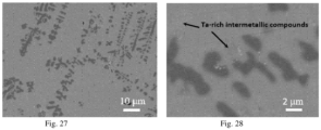
- the initial alloy melt contains a significant amount of Nb and Ta, apart from the minimal amount that may exist in the Fe y2 T z2 M a2 D b2 La x2 dispersed particle phase, they will also form dendritic intermetallic compound phases with Fe, Cr, and V, as shown in Comparative Example 4. These intermetallic compounds are not the iron alloy phases primarily concerned with solid-solution alloying in this application.
- the initial alloy melt contains only La and Fe
- the solidification rate of the alloy melt exceeds 10 6 K/s
- a certain amount of nearly spherical Fe phase particles with a nanoscale dimension can be obtained with insufficient dendritic growth.
- the Fe phase particles have a strong tendency for dendritic growth, they do not have time to grow fully and thus solidify and precipitate as nearly spherical Fe phase particles with insufficient dendritic growth at the nanoscale.
- the solidification rate of the La-Fe alloy melt is below 500 K/s, the dispersed particle phase will grow fully into large dendritic phases, and after the matrix phase is removed, the obtained dendritic Fe phase will be intertwined dendritic fibers, as shown in Comparative Example 1.
- the initial alloy melt contains La and Fe, as well as high-melting-point elements such as Cr, V, Mo, W, and Ti, especially when it contains T-type elements like Cr or V that can form a complete solid solution with Fe
- the primary particles that precipitate during the solidification of the initial alloy melt are Fe-rich and contain dissolved T-type elements. Due to the special solid solution behavior of T-type elements, the original lattice formation is disrupted, which hinders the growth of the Fe-rich dendritic phase along specific crystal orientations, leading to a tendency for the Fe-rich primary particles with dissolved T-type elements to become spherical.
- T-type elements are key to the discovery that Fe-rich primary particles can be spheroidized, especially when the Fe-rich dispersed particles are relatively large.
- T-type elements include at least one of the corrosion-resistant elements Cr and V.
- the solid solution formed by these elements with Fe is essentially stainless steel (corrosion resistance of V is even higher than that of Cr). Therefore, the dissolution of T-type elements significantly enhances the corrosion resistance of the Fe-rich dispersed particles.
- the matrix phase is primarily composed of highly corrosive La, it can be easily corroded and removed by reacting with an acid solution, leaving behind the dispersed Fe-rich phase particles.
- a cooling rate greater than 10 6 K/s can be used to prepare an initial alloy solid containing nano-sized Fe-rich spherical particles with T- and D-type elements. These nano-sized Fe-rich spherical particles, with their high corrosion resistance, can then be separated from the La-rich matrix through acid reaction, resulting in nano-sized Fe-rich spherical particles.
- M-type elements include at least one of Al, Ni, Co, and Si, which are key elements in commercial iron alloys.
- Al is a key element in Fe-Cr-AI electrical heating alloys and thermal spray coatings
- Ni is a key element in austenitic stainless steel Fe-Cr-Ni
- Co is a key element in Fe-Cr-Co permanent magnets
- Si is a key element in Fe-Cr-Si soft magnetic materials.
- the atomic percentage of Ni dissolved in the Fe-rich dispersed particles generally does not exceed 12%; Al and Co have a considerable solid solution in the Fe-rich dispersed particles (see examples), with atomic percentages that can even exceed 20%.
- the required content of M-type elements in most of the aforementioned commercial iron alloys is not very high, making it possible to prepare commercial iron alloy powders that meet the related composition requirements.
- M-type elements When the initial alloy melt contains M-type elements, some of these M-type elements are also present in the Fe-rich dispersed particles through solid solution. Therefore, M-type elements generally have a positive effect on the spheroidization of Fe-rich dispersed particles, as seen in Examples 13 and 14. Moreover, since both M-type elements and La react easily with acid solutions, they can be removed from the matrix phase through an acid corrosion reaction, resulting in freely dispersed Fe-rich dispersed particles. If the chemical activity difference between La and M-type elements is used, and a suitable acid solution is applied to selectively remove primarily La from the matrix phase according to the dealloying principle, freely dispersed Fe-rich dispersed particle powder and nano-porous M composite powder can be obtained.
- D-type elements include high-melting-point elements such as Mo, W, and Ti. Although these elements do not have as high a solubility in Fe as T-type elements (T-type elements are completely soluble in Fe), D-type elements have a solubility of 10%-20% in Fe and are completely soluble in T-type elements. Therefore, the appropriate addition of high-melting-point elements such as Mo, W, and Ti to the initial alloy melt can enhance the sphericity and corrosion resistance of the Fe-rich dispersed particles, while also significantly increasing the melting point and heat resistance of the Fe-rich dispersed particles. For example, Ti plays a role in the commercial austenitic stainless steel 1Cr18Ni9Ti, and Mo plays a role in the commercial ultra-high-temperature-resistant Fe-Cr-AI-Mo electrical heating alloy.
- this application builds on the La-Fe alloy, with T-type elements, M-type elements, and D-type elements carefully selected and designed. This selection ensures that during the solidification of the initial alloy melt, Fe, T-type elements, and D-type elements are primarily present in the Fe y2 T z2 M a2 D b2 La x2 dispersed particle phase, with M-type elements partially present in the Fe y2 T z2 M a2 D b2 La x2 dispersed particle phase; La and M-type elements are primarily present in the Lax1 Ma1 matrix phase.
- the spheroidization of Fe-rich dispersed particles is achieved by suppressing the formation and growth of Fe-rich dendritic phases through the alloying of special solid solution elements and the regulation of the melt cooling rate.
- the volume percentage of spherical or near-spherical dispersed particles in all dispersed particles can approach 100%, but it cannot reach 100%.
- the sphericity of the spherical or near-spherical dispersed particles exceeds 50%; Furthermore, the sphericity of the spherical or near-spherical dispersed particles exceeds 70%; Furthermore, the sphericity of the spherical or near-spherical dispersed particles exceeds 85%; Furthermore, the sphericity of the spherical or near-spherical dispersed particles exceeds 95%; Furthermore, the volume percentage of spherical or near-spherical dispersed particles in all dispersed particles is greater than 10%.
- spherical is used in some parts of this application, and “spherical or near-spherical” is used in others. In fact, throughout this application, “spherical” includes both spherical and near-spherical, as there is no ideal sphere in reality.
- La-Fe alloys hardly form spherical dispersed particles through the described method, or they require an extremely high cooling rate to obtain near-spherical Fe-phase particles smaller than 90 nm. Additionally, these particles are difficult to separate from the La matrix through acid reaction to obtain such nanoparticles (nano-Fe particles would also react with acid and dissolve). Therefore, through alloy design and the addition of corrosion-resistant elements like Cr or V, or with the addition of a significant amount of D-type elements, if the volume percentage of spherical or near-spherical dispersed particles in all dispersed particles exceeds 10%, it can be considered that a substantial amount of spherical or near-spherical dispersed particles has been obtained.
- the volume percentage of spherical or near-spherical dispersed particles in all dispersed particles exceeds 25%; Furthermore, the dispersed particles are primarily spherical or near-spherical in shape; Furthermore, the volume percentage of spherical or near-spherical dispersed particles in all dispersed particles exceeds 50%; Furthermore, the volume percentage of spherical or near-spherical dispersed particles in all dispersed particles exceeds 75%; Furthermore, the volume percentage of spherical or near-spherical dispersed particles in all dispersed particles exceeds 90%; Furthermore, the volume percentage of spherical or near-spherical dispersed particles in all dispersed particles exceeds 95%.
- the volume percentage of spherical or near-spherical dispersed particles in all dispersed particles exceeds 50%.
- the volume percentage of spherical or near-spherical dispersed particles in all dispersed particles exceeds 50%.
- the volume percentage of spherical or near-spherical dispersed particles in all dispersed particles exceeds 50%.
- the volume percentage of spherical or near-spherical dispersed particles in all dispersed particles exceeds 50%.
- the volume percentage of spherical or near-spherical dispersed particles in all dispersed particles exceeds 50%.
- the volume percentage of spherical or near-spherical dispersed particles in all dispersed particles exceeds 95%.
- the average particle size of the dispersed phase exceeds 0.25 ⁇ m, it is still possible to obtain dispersed particles with a sphericity of over 85%; Furthermore, when the average particle size of the dispersed phase exceeds 0.25 ⁇ m, it is still possible to obtain dispersed particles with a sphericity of over 85% through the regulation of cooling rate and alloy composition; Furthermore, when the average particle size of the dispersed phase exceeds 0.5 ⁇ m, it is still possible to obtain dispersed particles with a sphericity of over 85% through the regulation of cooling rate and alloy composition; Furthermore, when the average particle size of the dispersed phase exceeds 1 ⁇ m, it is still possible to obtain dispersed particles with a sphericity of over 85% through the regulation of cooling rate and alloy composition; Furthermore, when the average particle size of the dispersed phase exceeds 3 ⁇ m, it is still possible to obtain dispersed particles with a sphericity of over 85% through the regulation of cooling rate and alloy composition.
- some of the spherical or near-spherical dispersed particles have dendritic features, meaning that certain spherical or near-spherical dispersed particles exhibit protruding short dendrites, giving the entire spherical or near-spherical dispersed particle a shape similar to that of a "coronavirus" (the protruding short dendrites correspond to the crown-like protrusions on the coronavirus particles).
- the number of protruding short dendrites can be one or more, and their protrusion length from the spherical surface is less than the radius of the spherical particle; for specific shapes, see the examples. Furthermore, the number of protruding short dendrites can be one or more, and their protrusion length from the spherical surface is less than half of the spherical particle's radius.
- the shape of the dispersed particles is mainly spherical or near-spherical; in addition, the dispersed phase also contains a small amount of typical dendritic particles. These dendritic particles have a typical dendritic morphology, do not appear spherical, and are not included in the statistical range of spherical or near-spherical particles.
- the dispersed particles are mainly spherical or near-spherical in shape, and some spherical or near-spherical dispersed particles contain certain dendritic features; at the same time, the dispersed phase also contains a small amount of typical dendritic particles.
- the presence of these two types of dendritic features is a unique characteristic of the Fe-rich dispersed phase obtained through this application.
- the protrusion length of the protruding short dendrites from the spherical surface is less than one-third of the spherical particle's radius; Furthermore, the protrusion length of the protruding short dendrites from the spherical surface is less than one-fifth of the spherical particle's radius.
- the particle size of the dispersed phase ranges from 5nm to 40 ⁇ m; Furthermore, the particle size of the dispersed phase ranges from 5nm to 30 ⁇ m; Furthermore, the particle size of the dispersed phase ranges from 5nm to 20 ⁇ m; Furthermore, the particle size of the dispersed phase ranges from 5nm to 10 ⁇ m; Furthermore, the particle size of the dispersed phase ranges from 100nm to 50 ⁇ m; Furthermore, the particle size of the dispersed phase ranges from 250nm to 50 ⁇ m; Furthermore, the particle size of the dispersed phase ranges from 500nm to 50 ⁇ m; Furthermore, the particle size of the dispersed phase ranges from 5nm to 100nm; Furthermore, the particle size of the dispersed phase ranges from 5nm to 50nm.
- the size of the dispersed phase is inversely related to the solidification rate of the initial alloy melt, i.e., the higher the solidification rate, the smaller the particle size of the dispersed phase, the smaller the particle size of the dispersed phase, the higher the solidification rate of the initial alloy melt, and the higher the corresponding spheroidization rate of the dispersed phase, the higher the volume percentage of spherical or near-spherical dispersed particles in all dispersed particles.
- the proportion of single crystal particles in the dispersed phase is not less than 60% of the total number of particles.
- Step Three since the iron alloy powder material, with the primary components of Fe y2 T z2 M a2 D b2 La x2 , is obtained by removing the matrix phase from the initial alloy solid and retaining the dispersed phase, the characteristics (including particle shape) of the iron alloy powder material correspond to those of the dispersed phase described in Step Two. These characteristics are detailed in Step Two.
- the method of removing the matrix phase and retaining the dispersed phase includes at least one of acid solution dissolution and matrix oxidation-pulverization removal.
- an appropriate type and concentration of acid are chosen.
- the selection criteria ensure that the matrix phase, primarily composed of La x1 M a1 , dissolves into ions in the solution, while the dispersed phase, primarily composed of Fe y2 T z2 M a2 D b2 La x2 , does not react with the corresponding acid, thus achieving the removal of the matrix phase and obtaining iron alloy powder material primarily composed of Fe y2 T z2 M a2 D b2 La x2 .
- the appropriate acid type and concentration can be chosen to ensure that the matrix phase, primarily composed of La x1 M a1 , becomes nanoporous M (by mainly corroding La), while the dispersed phase, primarily composed of Fe y2 T z2 M a2 D b2 La x2 , does not react with the corresponding acid, resulting in a composite powder of nanoporous M and Fe y2 T z2 M a2 D b2 La x2 dispersed particles.
- the material forms ferritic stainless steel, and the dispersed phase, primarily composed of Fe y2 T z2 M a2 D b2 La x2 , exhibits excellent acid corrosion resistance.
- elements like La and M easily react with acid solutions, making it very easy to remove the La-rich matrix phase and obtain iron alloy powder material primarily composed of Fe y2 T z2 M a2 D b2 La x2 .
- the La-rich matrix phase in the initial alloy solid can also be removed by dry methods. After the La-rich matrix is oxidized and pulverized, the Fe-rich dispersed phase will automatically detach and can be collected based on its magnetic properties, thereby separating it from the La-rich matrix phase.
- the oxidation-pulverization process of the La-rich matrix phase in the initial alloy solid can be accelerated through heat treatment.
- the La-rich matrix phase can be rapidly oxidized and pulverized, thereby improving the separation efficiency.
- elements such as Cr and V
- the oxidation resistance of the Fe-rich particle phase is enhanced, and by controlling the heating temperature, the oxidation of the Fe-rich particles can be prevented.
- the heat treatment temperature ranges from 50°C to 1000°C; preferably, the heat treatment temperature ranges from 50°C to 600°C; and more preferably, the heat treatment temperature ranges from 50°C to 200°C.
- the volume percentage of spherical or near-spherical iron alloy powder particles in all iron alloy powder particles can be infinitely close to 100%, but not reach 100%.
- the shape of the iron alloy powder particles is mainly spherical or near-spherical, and some of the spherical or near-spherical iron alloy powder particles contain dendritic features that are not fully spheroidized.
- the sphericity (roundness) of the spherical or near-spherical iron alloy powder particles exceeds 50%;
- the sphericity of the spherical or near-spherical iron alloy powder particles exceeds 70%
- the sphericity of the spherical or near-spherical iron alloy powder particles exceeds 85%;
- the sphericity of the spherical or near-spherical iron alloy powder particles exceeds 95%
- volume percentage of spherical or near-spherical iron alloy powder particles in all iron alloy powder is greater than 10%
- volume percentage of spherical or near-spherical iron alloy powder particles in all iron alloy powder is greater than 25%;
- the shape of the iron alloy powder particles is mainly spherical or near-spherical;
- volume percentage of spherical or near-spherical iron alloy powder particles in all iron alloy powder is greater than 50%
- volume percentage of spherical or near-spherical iron alloy powder particles in all iron alloy powder is greater than 75%
- volume percentage of spherical or near-spherical iron alloy powder particles in all iron alloy powder is greater than 90%
- volume percentage of spherical or near-spherical iron alloy powder particles in all iron alloy powder is greater than 95%.
- the volume percentage of spherical or near-spherical iron alloy powder particles in all iron alloy powder particles is greater than 50%.
- the volume percentage of spherical or near-spherical iron alloy powder particles in all iron alloy powder particles is greater than 50%.
- the volume percentage of spherical or near-spherical iron alloy powder particles in all iron alloy powder particles is greater than 50%.
- the volume percentage of spherical or near-spherical iron alloy powder particles in all iron alloy powder particles is greater than 50%.
- the volume percentage of spherical or near-spherical iron alloy powder particles in all iron alloy powder particles is greater than 50%.
- the volume percentage of spherical or near-spherical iron alloy powder particles in all iron alloy powder particles is greater than 95%.
- some spherical or near-spherical iron alloy powder particles contain certain dendritic features, which refer to short dendritic protrusions growing on the spherical or near-spherical iron alloy powder particles, giving the entire spherical or near-spherical iron alloy powder particles a shape characteristic similar to that of a "coronavirus" (the short dendritic protrusions growing on the spherical or near-spherical iron alloy powder particles correspond to the crown-like protrusions on the surface of the coronavirus sphere).
- the specific shape of the short dendritic protrusions is described in the examples.
- the shape of the iron alloy powder particles is mainly spherical or near-spherical; in addition, the iron alloy powder particles also contain a small amount of typical dendritic powder particles.
- the shape of the iron alloy powder particles is mainly spherical or near-spherical, and some spherical or near-spherical iron alloy powder particles contain certain dendritic features; at the same time, the iron alloy powder particles also contain a small amount of typical dendritic particles.
- the presence of these two dendritic morphological features is a unique characteristic of the iron alloy powder particles obtained through this application.
- the particle size of the iron alloy powder particles ranges from 5nm to 40 ⁇ m; furthermore, the particle size of the iron alloy powder particles ranges from 5nm to 30 ⁇ m; furthermore, the particle size of the iron alloy powder particles ranges from 5nm to 20 ⁇ m; furthermore, the particle size of the iron alloy powder particles ranges from 5nm to 10 ⁇ m.
- the particle size of the iron alloy powder particles ranges from 100nm to 50 ⁇ m.
- the particle size of the iron alloy powder particles ranges from 250nm to 50 ⁇ m.
- the particle size of the iron alloy powder particles ranges from 500nm to 50 ⁇ m.
- the particle size of the iron alloy powder particles ranges from 5nm to 100nm.
- the particle size of the iron alloy powder particles ranges from 5nm to 50nm.
- the shape of the powder particles is still predominantly spherical.
- the shape of the powder particles is still predominantly spherical.
- the shape of the powder particles is still predominantly spherical.
- the shape of the powder particles is still predominantly spherical.
- the proportion of single crystal particles among all particles in the iron alloy powder particles is no less than 60%.
- La is an exception
- iron group elements Fe, Co, and Ni Fe is also an exception.
- the utilization of this characteristic is the basis for forming La-rich matrix phases and Fe-rich dispersed phases in the solidification structure of the initial alloy. On this basis, by selecting and controlling the content of T-type elements, M-type elements, and D-type elements, the original dendritic particles in the initial alloy melt are transformed into spherical or near-spherical particles during solidification.
- La may also contain a small amount of other rare earth elements. As long as the atomic percentage of other rare earth elements does not exceed 25% of the La raw material content, the impact on the process is minimal. These other rare earths dissolve in La, partially replacing La.
- the term La in the invention represents La rare earths and other rare earths.
- the composition of the initial alloy melt in step 1 also includes non-metallic impurity elements, which include at least one of O, N, H, P, S, Cl; the atomic percentage content of these non-metallic impurity elements in the initial alloy melt is greater than 0% and less than 10%.
- these non-metallic impurity elements are concentrated in the La-rich matrix phase, thereby purifying the Fe-rich dispersed particle phase. That is, the atomic percentage content of non-metallic impurity elements in the Fe-rich dispersed phases is lower than in the initial alloy melt; and the atomic percentage content of non-metallic impurity elements in the Fe-rich dispersed particle phase is less than 1.5%.
- the content of non-metallic impurity elements in the spherical or near-spherical iron alloy powder particles in step 3 is also lower than the content of non-metallic impurity elements in the initial alloy melt.
- the resulting iron alloy powder particles can be classified by particle size, such as separating powders larger than 10 ⁇ m, powders between 1 ⁇ m and 5 ⁇ m, powders between 5 ⁇ m and 10 ⁇ m, and powders smaller than 1 ⁇ m, to obtain spherical iron alloy powder materials of different sizes for various applications.
- the invention also relates to a spherical iron alloy powder material, wherein the spherical iron alloy powder material is prepared by using the preparation method described in the first aspect; some characteristics of the spherical iron alloy powder material include:
- the sphericity of the spherical or near-spherical iron alloy powder particles exceeds 65%.
- volume percentage of spherical or near-spherical iron alloy powder particles in all iron alloy powder particles is greater than 25%.
- the total atomic percentage of O, N, H, P, S, and Cl elements in the spherical or near-spherical iron alloy powder particles is less than 1.5%.
- T includes at least one of Cr or V
- M includes at least one of Al, Ni, Co, or Si
- D includes at least one of Mo, W, or Ti
- x1, a1, x2, y2, z2, a2, and b2 represent the atomic percentage content of the corresponding constituent elements respectively.
- the invention also relates to a method for preparing spherical iron-chromium-silicon powder materials with high silicon content.
- the method characterized in that the spherical iron alloy powder material prepared in steps 1 to 3 of claim 1, with Fe-Cr or low Si content Fe-Cr-Si as the main components, undergoes silicon infiltration treatment to obtain a high-Si-content spherical powder material with Fe-Cr-Si as the main component.
- the silicon infiltration treatment includes at least one of solid-state silicon infiltration, liquid-state silicon infiltration, or gas-phase silicon infiltration processes.
- the silicon source includes at least one of Si or silicon-rich alloys; for liquid-state silicon infiltration, the silicon source is primarily a Si-containing liquid; for gas-phase silicon infiltration, the silicon source is primarily a Si-containing gas.
- the treatment temperature for solid-state silicon infiltration is between 400°C and 1200°C.
- the invention provides an improved silicon infiltration process:
- the initial alloy solid described in step two of the first aspect is prepared according to steps one and two, wherein T includes Cr, M includes Si, and 0 ⁇ a ⁇ 40%; the average composition of the matrix phase is mainly La x1 Si a1 ; and the composition of the dispersed phase is mainly low-Si-content Fe y2 Cr z2 Si a2 D b2 La x2 ; in the La x1 Si a1 matrix phase, Si combines with La through intermetallic compounds; 0 ⁇ a2 ⁇ 8%; the La in the La x1 Si a1 matrix phase of the initial alloy solid is removed through dealloying reaction with a dilute acid solution, while Si in the original La x1 Si a1 matrix phase remains, forming a composite powder of nanoporous Si and the low-Si-content Fe y2 Cr z2 Si a2 D b2 La x2 particles; The nanoporous Si can then serve as a silicon source for the silicon infiltration of the low
- the nanoporous Si serves as a silicon source to perform silicon infiltration treatment on the low-Si-content Fe y2 Cr z2 Si a2 D b2 La x2 particles, resulting in high-Si-content spherical Fe-Cr-Si powder materials.
- the solid-state silicon infiltration method with nanoporous Si and the low-Si-content Fe y2 Cr z2 Si a2 D b2 La x2 particles includes: direct solid-state silicon infiltration or first compacting the particles before performing solid-state silicon infiltration.
- the treatment temperature for solid-state silicon infiltration is between 400°C and 1200°C.
- the resulting high-Si-content spherical Fe-Cr-Si powder materials primarily have a composition of Fe y3 Cr z3 Si a3 D b3 La x3 , where x3, y3, z3, a3, b3 represent the atomic percentage content of the corresponding constituent elements, and 0 ⁇ y3 ⁇ y2, 0 ⁇ z3 ⁇ z2, 0 ⁇ a2 ⁇ a3, 0 ⁇ b3 ⁇ b2, 0 ⁇ x3 ⁇ x2.
- the high-Si-content spherical Fe-Cr-Si powder material in addition to having increased Si content through silicon infiltration treatment, results in an automatically adjusted alloy composition, while the powder material's morphology and size remain largely consistent with those before the silicon infiltration treatment.
- the high-Si content spherical Fe-Cr-Si powder materials can be re-powderized into loose particles through dispersion and crushing techniques. Even if some unpenetrated residual nanoporous Si remains on the surface of the high-Si content spherical Fe-Cr-Si powder, it can sometimes be beneficial.
- the high-Si-content spherical Fe-Cr-Si powder particles are classified by particle size, such as separating powders larger than 10 ⁇ m, 1 ⁇ m-5 ⁇ m powders, 5 ⁇ m-10 ⁇ m powders, and powders smaller than 1 ⁇ m, to obtain spherical Fe-Cr-Si powder materials with different particle sizes and high Si content, which can be applied in various fields.
- the invention also relates to a high-silicon-content spherical iron-chromium-silicon powder material.
- This material is characterized by being prepared through the method described in the third aspect for high-silicon-content spherical iron-chromium-silicon powder materials, with specific features as described in the third aspect.
- the invention also relates to a composite powder of nanoporous Si and spherical Fe-Cr-Si particles. It is characterized by being prepared through the silicon infiltration improvement process described in the third aspect, resulting in a composite powder of nanoporous Si and low-Si content Fe y2 Cr z2 Si a2 D b2 La x2 particles. Specific features are as described in the third aspect's silicon infiltration improvement process.
- the invention also relates to a preparation method for high-nickel-content iron-chromium-nickel powder metallurgy products, characterized by including the following steps:
- the atomic percentage solubility of Ni in the Fe-rich dispersed phase generally does not exceed 12%.
- Ni content in Fe-Ni-based high-temperature alloys needs to reach 30%-40%. Therefore, by increasing the Ni content in low-Ni content Fe y2 Cr z2 Ni a2 D b2 La x2 particles using this method, high-Ni content iron-chromium-nickel powder metallurgy products suitable for high-temperature alloys can be obtained.
- Step 2 Although both La and Ni can react with acids, the reactivity of the rare earth La is higher, and the intermetallic compound typically contains more La. Therefore, by adjusting the type and concentration of the dilute acid, La can be removed through a de-alloying reaction, with only a small amount of Ni being inevitably dissolved. Most of the Ni can be retained as nanoporous Ni.
- the low-Ni content Fe y2 Cr z2 Ni a2 D b2 La x2 particles, containing Cr, are corrosion-resistant and can be completely retained.
- the nanoporous Ni has a particle size less than 200 nm.
- the resulting composite powder of nanoporous Ni and low-Ni content Fe y2 Cr z2 Ni a2 D b2 La x2 particles will have the low-Ni content particles freely separated and mixed with nanoporous Ni fragments.
- Step 3 Furthermore, the pressing and sintering treatment can be carried out sequentially or simultaneously; simultaneous processing is known as hot pressing sintering.
- the sintering treatment temperature is below the melting point of the low-Ni content Fe y2 Cr z2 Ni a2 D b2 La x2 particles.
- the sintering treatment temperature ranges from 400°C to 1400°C.
- the sintering treatment temperature ranges from 400°C to 1100°C.
- the sintering treatment temperature ranges from 400°C to 900°C.
- the nanoporous Ni infiltrates into the low-Ni content Fe y2 Cr z2 Ni a2 D b2 La x2 particles and solid dissolves within them, increasing the nickel content.
- the invention also relates to a high-nickel content iron-chromium-nickel powder metallurgy product, characterized by being prepared using the preparation method described in the sixth aspect.
- the specific features are as described in the sixth aspect.
- the invention also relates to a composite powder of nanoporous Ni and low-Ni content iron-chromium-nickel particles, characterized by being prepared through steps 1 and 2 of the method described in the sixth aspect.
- the specific features are as described in the sixth aspect.
- the invention also relates to the application of the spherical iron alloy powder material described in the second aspect in any of the following fields: ordinary powder metallurgy, metal injection molding (MIM), 3D printing, magnetic materials, heat-resistant materials, high-temperature alloys, coatings, and wave-absorbing materials.
- ordinary powder metallurgy metal injection molding (MIM), 3D printing, magnetic materials, heat-resistant materials, high-temperature alloys, coatings, and wave-absorbing materials.
- the spherical iron alloy powder materials related to the first and second aspects can be used. That is, the powder can be pressed into a compact and then directly sintered to produce a bulk powder metallurgy product of the corresponding composition, or the powder can be compounded with other powders, then pressed into a compact, and sintered to produce a bulk powder metallurgy product with the corresponding composite composition.
- the other powders include at least one of metal powders, alloy powders, oxide powders, carbide powders, nitride powders, carbon powders, or ceramic powders with other components.
- MIM metal injection molding
- the theoretically optimal powder particle size is 0.5 ⁇ m to 10 ⁇ m.
- the particle size of powders used in MIM is generally greater than 10 ⁇ m, even exceeding 50 ⁇ m.
- the method described in the invention is very suitable for producing powders in the 0.5 ⁇ m to 10 ⁇ m range, and finer powders are easier to produce. Therefore, the spherical iron alloy powder materials related to the first and second aspects are highly suitable for the metal injection molding (MIM) field.
- MIM technology uses a mixture of powder and organic binder to make the compact, which is then sintered to produce the product after removing the organic binder. Due to the removal of the binder, there is a 10% to 20% volume shrinkage in the sintered product relative to the compact.
- fine powder for 3D printing typically requires spherical powders with particle sizes of about 15 ⁇ m to 53 ⁇ m.
- spherical iron alloy powders within this particle size range can be obtained, and further screening can concentrate powders within this particle size range. Therefore, the spherical iron alloy powder materials related to the first and second aspects can also be used in 3D printing in certain cases.
- the spherical iron alloy powder materials related to the first and second aspects can also be used in soft magnetic materials or hard magnetic materials (permanent magnets).
- powders with a main composition of Fe-Cr or Fe-Cr-Si can be used for soft magnetic materials (such as magnetic powder cores), while powders with a main composition of Fe-Cr-Co can be used for hard magnetic materials.
- the iron alloy powder materials with a main composition of Fe-Cr or Fe-Cr-Si are used for soft magnetic materials, they can include applications as magnetic powder cores.
- the magnetic powder cores are coated with an insulating coating material and then pressed at a certain temperature; the pressing temperature ranges from room temperature to 800°C.
- the weight percentage of the insulating coating material in the magnetic powder core exceeds 0.1% and is less than 15%.
- the insulating coating material includes resin; preferably, the insulating coating material includes at least one of silicone resin, phenolic resin, epoxy resin, polypropylene, or nylon.
- the spherical iron alloy powder materials related to the first and second aspects containing high melting point elements such as V, W, Mo, Ti, or those containing Al and capable of forming an alumina heat-resistant protective layer at high temperatures such as spherical iron alloy powders with main elements of Fe-Cr-AI or Fe-Cr-AI-(V/W/Mo/Ti), are used to significantly enhance heat resistance.
- These powders can be used in various industrial applications, such as heating furnaces, heat exchangers, fiber burners, and hot gas filtration systems.
- iron-chromium-aluminum alloy products offer significant advantages over traditional ceramic honeycomb carriers.
- the spherical iron alloy powder materials related to the first and second aspects containing high melting point elements such as V, W, Mo, Ti exhibit excellent high-temperature resistance.
- the composition of the spherical iron alloy powder materials related to the first and second aspects containing high melting point elements such as V, W, Mo, Ti matches or is close to that of high-temperature alloys, they can be used in high-temperature alloy applications.
- the spherical iron alloy powder materials related to the first and second aspects can serve as key components in coatings, including thermal spray coatings, resin-based coatings, and magnetic shielding coatings.
- the spherical iron alloy powder materials from the first and second aspects can be used as magnetic metal powders for wave-absorbing materials.
- the invention also relates to the application of the spherical iron alloy powder material described in the second aspect in the field of electrical heating materials, where the main composition includes Fe-Cr-Al.
- powder materials related to the first and second aspects with main elements of Fe-Cr-AI or Fe-Cr-AI-(V/W/Mo/Ti) are excellent for use as electrical heating elements after being processed through powder metallurgy.
- iron-chromium-aluminum electrical heating alloy components made from these powders with main elements of Fe-Cr-AI or Fe-Cr-AI-(V/W/Mo/Ti) can operate at temperatures above 1400°C.
- the high aluminum content in Fe-Cr-Al alloys provides high electrical resistivity, reaching up to 1.6 ⁇ .m. High resistivity effectively converts electrical energy into thermal energy.
- iron-chromium-aluminum alloys are cost-effective, being 20% to 25% cheaper than nickel-chromium alloys, which facilitates their widespread use. They also have good heat resistance, low density, and excellent high-temperature oxidation resistance, making them widely used in various industrial and household applications. For instance, in domestic settings, iron-chromium-aluminum powder metallurgy alloys are used in heating elements such as electric furnace wires, electric furnace rods, cooking plates, radiators, toasters, microwaves, water heaters, washing machines, boilers, and precision resistance components in automobiles.
- the invention also relates to the application of the high-silicon content spherical iron-chromium-silicon powder materials described in the fourth aspect in magnetic materials.
- the high-silicon content spherical iron-chromium-silicon powder materials from the fourth aspect are used in soft magnetic materials, they can include applications as magnetic powder cores.
- the magnetic powder cores are coated with an insulating coating material using the high-silicon content spherical iron-chromium-silicon powder materials and then pressed at a certain temperature; the pressing temperature ranges from room temperature to 800°C.
- the weight percentage of the insulating coating material in the magnetic powder core exceeds 0.1% and is less than 15%.
- the insulating coating material includes resin; preferably, the insulating coating material includes at least one of silicone resin, phenolic resin, epoxy resin, polypropylene, or nylon.
- the invention also relates to the application of the high-nickel content iron-chromium-nickel powder metallurgy products described in the seventh aspect in high-temperature alloys.
- High-temperature alloys mainly include nickel-based, iron-based, and nickel-iron-based high-temperature alloys.
- composition of the high-nickel content iron-chromium-nickel powder metallurgy products described in the seventh aspect of this invention is the same as or close to that of high-temperature alloys, they can be used in the high-temperature alloy field.
- the invention also relates to an alloy solid, characterized in that it is prepared by the method of preparing the initial alloy solid described in steps one and two of the first aspect; the specific features are detailed in the first aspect.
- the composition of the initial alloy melt in step one also includes non-metallic impurity elements, which include at least one of O, N, H, P, S, or Cl; the atomic percentage content of the non-metallic impurity elements in the initial alloy melt is greater than 0 and less than 10%; during the formation of the Fe-rich dispersed particle phase in step two, non-metallic impurity elements are concentrated in the La-rich matrix phase, thereby purifying the Fe-rich dispersed particle phase; that is, the atomic percentage content of the non-metallic impurity elements in the Fe-rich dispersed particle phase is lower than that in the initial alloy melt; and in the Fe-rich dispersed particle phase, the atomic percentage content of the non-metallic impurity elements is less than 1.5%.
- the invention also relates to the application of the spherical iron alloy powder material described in the second aspect in the field of magnetorheological fluids.
- the characteristics of this spherical iron alloy powder material are detailed in the first and second aspects; some characteristics of the spherical iron alloy powder material include: the main component of the spherical iron alloy powder material is Fe y2 T z2 M a2 D b2 La x2 ; wherein 50% ⁇ y2 ⁇ 98%, 0.2% ⁇ z2 ⁇ 50%, 0% ⁇ a2 ⁇ 30%, 0% ⁇ b2 ⁇ 35%, 0 ⁇ x2 ⁇ 5%; the shape of the iron alloy powder particles is mainly spherical or near-spherical, with some spherical or near-spherical iron alloy powder particles exhibiting certain dendritic characteristics; the particle size of the iron alloy powder particles ranges from 5 nm to 100 nm; T includes at least one of Cr or V, M includes at least one of Al, Ni, Co, or Si, and D includes at least one of Mo, W, or Ti; x1, a1, x2, y2, z2, a2, b2 represent the
- the particle size of the spherical iron alloy powder particles is 5 nm to 50 nm; Further preferably, the particle size of the spherical iron alloy powder particles is 5 nm to 25 nm; Furthermore, 50% ⁇ y2 ⁇ 95%;
- the spherical iron alloy powder material described in the invention which pertains to both its first and second aspects, can be used in this field. Specifically, this involves: mixing the spherical iron alloy powder with a carrier liquid and a surfactant evenly to obtain a magnetorheological fluid.
- the carrier liquid includes at least one of water, ethanol, carbohydrates, fats, diester, or mercury.
- the surfactant includes at least one of oleic acid, polyvinylpyrrolidone, polyethylene glycol, ethylene glycol, or sodium dodecylbenzenesulfonate.
- Magnetic solid particles for magnetorheological fluids generally require nanometer-scale particles.
- Iron (Fe) is one of the best magnetic materials, but when nano Fe particles are used as magnetic solid particles in magnetorheological fluids, they are prone to oxidation, which leads to instability and poor application performance.
- This invention effectively addresses this problem.
- the spherical Fe alloy powder particles are alloyed with a certain amount of corrosion-resistant elements such as Cr, V, Mo, W, and Ti, it not only makes the spherical shape more pronounced but also significantly improves the corrosion resistance of the nano Fe alloy powder particles. This improvement in corrosion resistance allows for the removal of the matrix from the alloy solid through acid corrosion while retaining the nano Fe alloy powder particles. Additionally, it makes it possible to use corrosion-resistant nano Fe alloy powder particles as magnetic solid particles in magnetorheological fluids.
- the invention also relates to a coronavirus-shaped spherical iron alloy powder particle, including the following features:
- the main component of the coronavirus-like spherical iron alloy powder particle is Fe y2 T z2 M a2 D b2 La x2 , wherein 50% ⁇ y2 ⁇ 98%, 0.2% ⁇ z2 ⁇ 50%, 0% ⁇ a2 ⁇ 30%, 0% ⁇ b2 ⁇ 35%, O ⁇ x2 ⁇ 5%;
- T includes at least one of Cr or V
- M includes at least one of Al, Ni, Co, or Si
- D includes at least one of Mo, W, or Ti
- La is the rare earth element La
- the coronavirus-like spherical iron alloy particles with the main component of Fe y2 T z2 M a2 D b2 La x2 contains La in a solid solution;
- x1, a1, x2, y2, z2, a2, b2 represent the atomic percentage content of the corresponding constituent elements respectively;
- the coronavirus-like spherical iron alloy powder particle include a main body part and a protruding part; the main body part is a spherical or nearly spherical sphere, and the protruding part consists of multiple protrusions grown in situ on the surface of the main body sphere; the spherical iron alloy powder particle has a coronavirus-like shape, wherein the multiple protrusions of the protruding part correspond to the multiple corona-like protrusions of a coronavirus; the diameter of the main body sphere of the coronavirus-like spherical iron alloy powder particle is 20 nm to 50 ⁇ m, and the height of the protrusions on the protruding part is less than 0.3 times the diameter of the main body sphere.
- the number of protrusions on any single coronavirus-like spherical iron alloy powder particle exceeds 5;
- the number of protrusions on any single coronavirus-like spherical iron alloy powder particle exceeds 10;
- the diameter of the main body sphere of the coronavirus-like spherical iron alloy powder particle is 50 nm to 15 ⁇ m;
- the diameter of the main body sphere of the coronavirus-like spherical iron alloy powder particle is 200 nm to 10 ⁇ m;
- the diameter of the main body sphere of the coronavirus-like spherical iron alloy powder particle is 200 nm to 5 ⁇ m;
- any single protrusion on the protruding part consists of no more than one crystal grain, and the crystal structure and crystal plane orientation of this grain are the same as those of the sphere part it connects with.
- the main body part and the protruding part of the coronavirus-like spherical iron alloy powder particle are both part of a large single crystal. Due to the consistent crystal structure and crystal plane orientation at the boundary between the main body and the protruding part, the main body sphere and the multiple protrusions of the coronavirus-like spherical iron alloy powder particle are considered to belong to a large single crystal.
- the height of the protrusions on the protruding part is less than 0.2 times the diameter of the main body sphere.
- the protrusions are dendritic, meaning that they are preferred growth points where spherical particles transition to dendritic particles.
- certain locations on the sphere become preferred growth points, resulting in protrusions growing according to the original crystal structure and crystal plane orientation of the growth points.
- the diameter of the protrusions on the protruding part is less than 0.25 times the diameter of the main body sphere of the coronavirus-like spherical iron alloy powder particle.
- the morphological features of the coronavirus-like spherical iron alloy powder particle can be referenced from the shapes shown in Figures 3 , 11 , 12 , and 15 of the examples.
- coronavirus-like spherical iron alloy powder particle is prepared by using the method described in the first aspect.
- the beneficial effects of the present invention are mainly reflected in the following aspects:
- the design by adding T-type elements achieves the precipitation and subsequent separation of corrosion-resistant, oxidation-resistant spherical or near-spherical Fe-rich dispersed particles in a La-rich matrix.
- T-type elements are fully soluble with Fe and can be added in large amounts; T-type elements, like Fe, do not form any intermetallic compounds with La and almost do not enter the La-rich phase, only entering the Fe-rich dispersed particles; the solid solution of T-type elements makes the Fe-rich dispersed particles tend to become spherical, which is key to preparing spherical or near-spherical Fe alloy powders; T-type elements are fully soluble with D-type elements.
- T-type elements When the solubility of D-type elements in Fe is 10%-20%, the presence of T-type elements allows more D-type elements to be solubilized in the Fe-rich dispersed particles; T-type elements like Cr and V are corrosion-resistant in Fe alloys. When they enter in the Fe-rich dispersed particles, they significantly improve the corrosion and oxidation resistance of these particles, making it possible to separate the Fe-rich dispersed particles from the La-rich matrix through acid etching or oxidize-pulverize process. Otherwise, pure Fe phases are also prone to react with acids and easy oxidized, especially when the particles are relatively small.
- the spherical or near-spherical Fe alloy powders directly solubilize beneficial rare earth elements. Adding rare earth elements to Fe alloys promotes the performance of the materials. For example, adding a small amount of rare earth elements to Fe-Cr-Al electric heating alloys improves the alloy's performance. In industry, rare earth elements added to Fe alloys are prone to oxidation. When added in small amounts, rare earth elements generally combine with impurities like oxygen in the alloy, resulting in uneven distribution as oxide particles, which limits the improvement in alloy performance. However, in this application, the initial alloy melt contains a significant amount of La (with the volume percentage of the La-rich matrix phase being more than 40%).
- the oxygen in the alloy melt mainly exists in the La-rich matrix, while a small amount of La is solid-solved in the spherical or near-spherical Fe alloy powders.
- This La in atomic form, is uniformly solid-solved in the Fe alloy powders and acts as a truly alloying rare earth element, which has a more positive effect on the material's properties.
- the presence of solubilized rare earth elements (La) in the Fe alloy powders is one of the key features of the Fe alloy powder materials prepared by this invention.
- spherical or near-spherical Fe alloy particles are advantageous due to their excellent flowability, uniformity, and powder stacking density, making them key raw materials for powder metallurgy, powder coating, powder spraying, metal injection molding (MIM), and 3D printing.
- MIM metal injection molding
- spherical Fe alloy powders cannot be prepared by chemical methods and are primarily produced by atomization, which involves high-speed fluid directly breaking liquid metal or alloys to obtain metal powders.
- atomization capabilities it is generally suitable only for spherical Fe alloy powders with sizes between 10 ⁇ m and 150 ⁇ m.
- Some of the spherical or near-spherical Fe alloy powder particles contain dendritic short branches.
- the strength of the green body is a key factor for normal production.
- green bodies are made by pressing metal powders with organic binders, followed by removal of the organic binder. The final product has high strength after sintering and shrinkage. Before sintering, the green body relies on the mechanical bonding between particles to maintain its shape after the organic binder is removed. If all metal powders are ideal spherical particles, the mechanical-friction bonding force between such ideal spherical particles is very weak, which can cause the green body to collapse.
- some spherical or near-spherical Fe alloy powder particles have dendritic short branches. This feature has little effect on the sphericity of the particles but significantly enhances the mechanical or frictional bonding force between particles, thus increasing the strength of the green body. If all particles had this dendritic feature, it could affect the powder flowability.
- the Fe alloy powders prepared in this application are well-balanced, with this dendritic short branch feature appearing only on some of the spherical or near-spherical Fe alloy powder particles.
- the dendritic short branches on some spherical Fe alloy powder particles are another key feature of the Fe alloy powders prepared by this invention.
- the initial alloy is prepared from raw materials containing impurities like O, N, H, P, S, Cl, or with lower purity, or if such impurities are introduced during the melting process, it will not affect the final ability to obtain Fe-rich dispersed particles with low levels of these impurities, and thus, low-impurity spherical iron alloy powder materials can also be obtained. This is because the impurities in the raw materials or introduced during melting are mostly captured by the La-rich matrix during the solidification of the initial alloy melt, thus purifying the Fe-rich dispersed particles.
- the process can yield Fe alloy powder materials predominantly composed of single-crystal particles. Compared to polycrystalline powders, single-crystal powders provide several significant and beneficial effects.
- each internal particle nucleates from a specific location in the melt and grows according to a particular atomic arrangement.
- the volume percentage of the matrix phase By controlling the volume percentage of the matrix phase to ensure that each internal particle can be dispersed, it becomes difficult for the internal dispersed particles to bond or entangle. Therefore, the Fe-rich dispersed particles obtained are mostly single-crystalline. Even if dendritic short branches further grow on the spherical particles, they grow according to the fixed crystal orientation on the surface of the sphere, meaning the sphere and the dendritic branches are part of the same crystal grain.
- Polycrystalline materials generally have impurity elements along the grain boundaries, making it difficult to obtain high-purity polycrystalline powder materials.
- the powder material mainly consists of single-crystal particles, its purity is assured.
- single-crystal particle surfaces have specific atomic arrangements, such as (111) face arrangements, which confer unique mechanical, physical, and chemical properties to the material, resulting in beneficial effects.
- the invention achieves the alloying of T-type, M-type, and D-type elements, as well as La, in a spherical or near-spherical Fe-rich dispersed particle phase by carefully designing and adding these elements to an alloy melt primarily composed of La and Fe. This improves the corrosion and oxidation resistance of the spherical or near-spherical Fe-rich dispersed particles and reduces impurity content.
- ultrafine spherical iron alloy powder materials with sizes ranging from hundreds of nanometers to several micrometers are obtained. These materials have excellent application prospects in fields such as powder metallurgy, metal injection molding (MIM), 3D printing, magnetic materials, heat-resistant materials, high-temperature alloys, coatings, electrical heating materials, and wave-absorbing materials.
- T includes at least one of Cr or V
- M includes at least one of Al, Ni, Co, or Si
- D includes at least one of Mo, W, or Ti.
- an initial alloy melt with a nominal atomic composition of La 50 Fe 41 Cr 9 was prepared.
- the melt was solidified at a cooling rate of about 100 K/s into an initial alloy sheet with a thickness of approximately 5 mm.
- the solidification structure of the initial alloy sheet is shown in Figure 1 and includes a dispersed particle phase primarily composed of Fe 79 Cr 20 La 1 and a La-rich matrix phase, where the matrix phase volume fraction exceeds 65%. Both Cr and La are solid-solution in the dispersed particle phase.
- the dispersed particle phase includes spherical and dendritic particles, with spherical particles comprising more than 50% of the volume fraction.
- the particle size range of the spherical particles is 15 nm to 60 ⁇ m.
- the La matrix phase in the initial alloy sheet was removed by reaction with a 0.5 mol/L dilute hydrochloric acid solution, resulting in a dispersed Fe alloy powder material primarily composed of Fe 79 Cr 20 La 1 .
- This powder includes spherical and dendritic particles, with spherical particles constituting more than 50% of the volume fraction.
- the particle size range of the spherical particles is 15 nm to 60 ⁇ m, as shown in Figure 2 .
- Some spherical or near-spherical particles have certain dendritic features, such as the small dendritic protrusions shown in the inset of Figure 2 .
- the prepared Fe alloy powder material is suitable for conventional powder metallurgy and metal injection molding (MIM) applications.
- an initial alloy melt with a nominal atomic composition of La 50 Fe 41 Cr 9 was prepared.
- the melt was solidified using a chill roll method at a cooling rate of about 5000 K/s into an initial alloy strip with a thickness of approximately 200 ⁇ m.
- the solidification structure of the initial alloy strip is shown in Figure 3 and includes a dispersed particle phase primarily composed of Fe 77 Cr 22 La 1 and a La-rich matrix phase, where the matrix phase volume fraction exceeds 65%.
- the dispersed particle phase is almost entirely composed of spherical particles.
- Some spherical particles contain certain dendritic features, such as the small dendritic protrusions shown in the inset of Figure 3 .
- the particle size range of the spherical particles is 15 nm to 10 ⁇ m.
- the matrix phase in Figure 3 was magnified, revealing some nanometer-sized spherical particles, as shown in Figure 4 .
- the La matrix phase in the initial alloy strip was reacted and removed.
- the particle size range of the spherical particles is 15 nm to 10 ⁇ m.
- the prepared powder material is suitable for conventional powder metallurgy and metal injection molding (MIM) applications.
- an initial alloy melt with a nominal atomic composition of La 67 Fe 30 V 3 was prepared.
- the melt was solidified at a cooling rate of about 1000 K/s into an initial alloy strip with a thickness of approximately 500 ⁇ m.
- the solidification structure of the initial alloy strip is shown in Figure 5 and includes a dispersed particle phase primarily composed of Fe 88.5 V 9 La 1.5 and a La-rich matrix phase, where the matrix phase volume fraction exceeds 70%.
- the dispersed particle phase is primarily spherical, with a particle size range of 15 nm to 5 ⁇ m. Enlarging the matrix phase in Figure 5 reveals some nanometer-sized spherical particles, as shown in Figure 6 (with the matrix phase outside the nanometer-sized spherical particles). A small amount of the dispersed particles are dendritic.
- the La matrix phase in the initial alloy strip was removed by reaction with a 0.5 mol/L dilute hydrochloric acid solution. This resulted in a dispersed Fe alloy powder material primarily composed of Fe 88.5 V 9 La 1.5 , with a shape mainly of spherical particles and only a small amount of dendritic particles.
- the particle size range of the spherical particles is 15 nm to 5 ⁇ m.
- an initial alloy melt with a nominal atomic composition of La 67 Fe 30 Cr 3 V 3 was prepared.
- the initial alloy melt, with a composition approximately La 65 Fe 30 Cr 3 V 3 O 2 was solidified at a cooling rate of about 250 K/s into an initial alloy thick strip with a thickness of approximately 3 mm.
- the solidification structure of the initial alloy thick strip is shown in Figure 7 and includes a dispersed particle phase primarily composed of Fe 82.3 V 8 Cr 8 La 1.5 O 0.2 and a La-rich matrix phase enriched with oxygen impurities, where the matrix phase volume fraction exceeds 70%.
- the dispersed particle phase is primarily spherical, with a small amount of dendritic particles.
- the particle size range of the spherical particles is 15 nm to 15 ⁇ m, and some spherical particles have certain dendritic features.
- the La-rich matrix phase in the initial alloy thick strip was removed by reaction with a 0.2 mol/L dilute nitric acid solution.
- Some spherical particles exhibit certain dendritic features.
- the particle size range of the spherical particles is 15 nm to 15 ⁇ m.
- an initial alloy melt with a nominal atomic composition of La 50 Fe 40 Cr 0.5 Mo 9.5 was prepared.
- the initial alloy melt was solidified at a cooling rate of about 250 K/s into an initial alloy thick strip with a thickness of approximately 3 mm.
- the solidification structure of the initial alloy thick strip is shown in Figure 8 and includes a dispersed particle phase primarily composed of Fe 78 Mo 20 Cr 1 La 1 and a La-rich matrix phase, where the matrix phase volume fraction exceeds 70%.
- the dispersed particle phase is primarily spherical, with a particle size range of 15 nm to 15 ⁇ m, and some spherical particles have certain dendritic features.
- the La matrix phase in the initial alloy thick strip was removed by reaction with a 0.5 mol/L dilute hydrochloric acid solution. This resulted in a dispersed Fe alloy powder material primarily composed of Fe 78 Mo 20 Cr 1 La 1 , with a shape mainly of spherical particles, and some spherical particles exhibiting certain dendritic features.
- the particle size range of the spherical particles is 15 nm to 15 ⁇ m.
- an initial alloy melt with a nominal atomic composition of La 34 Fe 40 Cr 2.5 Si 23.5 was prepared.
- the melt was solidified at a cooling rate of about 100 K/s into an initial alloy thick strip with a thickness of approximately 5 mm.
- the solidification structure of the initial alloy thick strip is shown in Figure 9 and includes a black dispersed particle phase primarily composed of Fe 85.2 Cr 8 Si 6 La 0.8 , a white matrix phase primarily composed of La 64 Si 36 , and a gray matrix phase primarily composed of La 34 Si 33 Fe 33 , where the volume fraction of the two matrix phases exceeds 70%.
- the dispersed particle phase is mainly near-spherical, with a particle size range of 50 nm to 5 ⁇ m.
- the La 64 Si 36 and La 34 Si 33 Fe 33 matrix phases in the initial alloy thick strip were removed by reaction with a mixed solution of 0.5 mol/L dilute hydrochloric acid and 1 mol/L hydrofluoric acid. This resulted in a dispersed Fe 85.2 Cr 8 Si 6 La 0.8 alloy powder material with a shape primarily of near-spherical particles, and the particle size range is 50 nm to 5 ⁇ m.
- the prepared powder material can be used in the field of magnetic materials, such as magnetic powder cores.
- an initial alloy melt with a nominal atomic composition of La 34 Fe 40 Cr 2.5 Si 23.5 was prepared.
- the melt was solidified at a cooling rate of about 10 5 K/s into an initial alloy strip with a thickness of approximately 100 ⁇ m.
- the solidification structure of the initial alloy strip is shown in Figure 10 and includes a black dispersed particle phase primarily composed of Fe 82.5 Cr 8 Si 8 La 1.5 and a matrix phase with an average composition of La 60 Si 20 Fe 20 , where the matrix phase volume fraction is greater than 70%.
- the dispersed particle phase is mainly fine spherical particles, with a particle size range of 15 nm to 2 ⁇ m.
- the matrix phase with an average composition of La 60 Si 20 Fe 20 in the initial alloy strip was removed by reaction with a mixed solution of 0.5 mol/L dilute hydrochloric acid and 1 mol/L hydrofluoric acid. This resulted in a dispersed Fe 82.5 Cr 8 Si 8 La 1.5 , containing Si alloy powder material with a shape primarily of near-spherical particles, and the particle size range is 15 nm to 2 ⁇ m.
- the prepared powder material can be used in the field of magnetic materials, such as magnetic powder cores.
- an initial alloy melt with a nominal atomic composition of La 50 Fe 40 Cr 5 Si 5 was prepared.
- the melt was solidified at a cooling rate of about 250 K/s into an initial alloy thick strip with a thickness of approximately 3 mm.
- the solidification structure of the initial alloy thick strip is shown in Figure 11 and includes a dispersed particle phase primarily composed of Fe 86 Cr 12 Si 1 La 1 and a matrix phase primarily composed of La 92 Si 8 , where the matrix phase volume fraction exceeds 70%.
- the dispersed particle phase is mainly spherical, with a small amount of dendritic particles, and some spherical particles have certain dendritic features.
- the particle size range of the spherical particles is 15 nm to 40 ⁇ m.
- the LaSi matrix phase in the initial alloy thick strip was removed by reaction with a mixed solution of 0.5 mol/L dilute hydrochloric acid, 0.1 mol/L dilute nitric acid, and 0.5 mol/L hydrofluoric acid (HF can remove Si).
- HF hydrofluoric acid
- the particle size range of the spherical particles is 15 nm to 40 ⁇ m, as shown in Figure 12 .
- an initial alloy melt with a nominal atomic composition of La 50 Fe 41 Cr 4 Si 5 was prepared.
- the melt was solidified at a cooling rate of about 1000 K/s into an initial alloy strip with a thickness of approximately 500 ⁇ m.
- the solidification structure of the initial alloy strip includes a dispersed particle phase primarily composed of Fe 90.5 Cr 8 Si 0.5 La 1 and a matrix phase primarily composed of La 94 Si 6 , where the matrix phase volume fraction exceeds 70%.
- the dispersed particle phase is mainly spherical, with a small amount of dendritic particles, and some spherical particles exhibit certain dendritic features.
- the particle size range of the spherical particles is 15 nm to 10 ⁇ m.
- the LaSi matrix phase in the initial alloy strip was removed by reaction with 0.5 mol/L dilute hydrochloric acid, while retaining most of the Si (Si generally does not react with dilute hydrochloric acid), resulting in a composite powder of Fe 90.5 Cr 8 Si 0.5 La 1 alloy and nano-porous Si.
- the nano-porous Si has a fragmented porous structure, and the iron alloy powder is mainly spherical, with a small amount of dendritic particles, and some spherical particles exhibit certain dendritic features.
- the particle size range of the spherical particles is 15 nm to 10 ⁇ m.
- the spherical iron alloy powder and nano-porous Si composite powder were pressed and densified, then solid siliconized in a vacuum at 1000°C for 4 hours, followed by powder dispersion. This resulted in a high-silicon content iron-chromium-silicon powder with a composition of approximately Fe 82 Cr 7 Si 10 La 1 .
- the high-silicon content iron-chromium-silicon powder after screening, selects particles with a size range of 3 ⁇ m to 10 ⁇ m, which can be used in the field of soft magnetic materials, such as magnetic powder cores.
- an initial alloy melt with a nominal atomic composition of La 45 Fe 27.5 Cr 7.5 Al 20 was prepared.
- the melt was solidified at a cooling rate of about 250 K/s into an initial alloy thick strip with a thickness of approximately 3 mm.
- the solidification structure of the initial alloy thick strip is shown in Figure 13 and includes a dispersed particle phase primarily composed of Fe 72 Cr 20 Al 7 La 1 and a matrix phase primarily composed of La 75 Al 25 , where the volume fraction of the matrix phase exceeds 70%.
- the dispersed particle phase is mainly spherical, with a small amount of dendritic particles, and some spherical particles exhibit certain dendritic features.
- the particle size range of the spherical particles is 15 nm to 10 ⁇ m.
- the La 75 Al 25 matrix phase in the initial alloy thick strip was removed by reaction with 0.5 mol/L dilute hydrochloric acid, resulting in a dispersed Fe 72 Cr 20 Al 7 La 1 alloy powder material.
- the shape is primarily spherical particles, with a small amount of dendritic particles, and some spherical particles exhibit certain dendritic features.
- the particle size range is 15 nm to 10 ⁇ m.
- the prepared powder material can be used in fields such as electrical heating alloys, heat-resistant alloys, and heat-resistant coatings.
- an initial alloy melt with a nominal atomic composition of La 45 Fe 27.5 Cr 7.5 Al 20 was prepared.
- the melt was solidified at a cooling rate of about 10 4 K/s into an initial alloy thin strip with a thickness of approximately 150 ⁇ m.
- the solidification structure of the initial alloy thin strip is shown in Figure 14 and includes a dispersed particle phase primarily composed of Fe 71 Cr 21 Al 7 La 1 and a matrix phase primarily composed of La 75 Al 25 , where the volume fraction of the matrix phase exceeds 70%.
- the dispersed particle phase is almost entirely spherical, with some spherical particles exhibiting certain dendritic features.
- the particle size range of the spherical particles is 5 nm to 5 ⁇ m.
- the La 75 Al 25 matrix phase in the initial alloy thin strip was removed by reaction with 0.5 mol/L dilute hydrochloric acid, resulting in a dispersed Fe 71 Cr 21 Al 7 La 1 alloy powder material.
- the shape is almost entirely spherical, with some spherical particles exhibiting certain dendritic features, as shown in Figure 15 .
- the particle size range is 5 nm to 5 ⁇ m.
- the prepared powder material can be used in fields such as electrical heating alloys, heat-resistant alloys, and heat-resistant coatings.
- an initial alloy melt with a nominal atomic composition of La 38 Fe 25 Cr 10 Al 25 Mo 2 was prepared.
- the melt was solidified at a cooling rate of about 500 K/s into an initial alloy thick strip with a thickness of approximately 1 mm.
- the solidification structure of the initial alloy thick strip is shown in Figure 16 and includes a dispersed particle phase primarily composed of Fe 60 Cr 25 Al 8 Mo 6 La 1 and matrix phases primarily composed of La 50 Al 50 (gray plate-like and fibrous phases) and La 75 Al 25 (white phase), where the overall volume fraction of the matrix phases exceeds 70%.
- the dispersed particle phase is mainly spherical, with a small amount of dendritic particles, and some spherical particles exhibit certain dendritic features.
- the particle size range of the spherical particles is 15 nm to 40 ⁇ m.
- the La 50 Al 50 and La 75 Al 25 matrix phases in the initial alloy thick strip were removed by reaction with 1 mol/L dilute hydrochloric acid, resulting in a dispersed Fe 60 Cr 25 Al 8 Mo 6 La 1 alloy powder material.
- the shape is primarily spherical particles, with a small amount of dendritic particles, and some spherical particles exhibit certain dendritic features.
- the particle size range is 15 nm to 40 ⁇ m.
- the prepared powder material can be used in fields such as electrical heating alloys, heat-resistant alloys, and heat-resistant coatings. Due to the presence of Mo, the powder material has higher temperature resistance and corrosion resistance.
- an initial alloy melt with a nominal atomic composition of La 27.5 Fe 37.5 Cr 10 Co 25 was prepared.
- the melt was solidified at a cooling rate of about 250 K/s into an initial alloy thick strip with a thickness of approximately 3 mm.
- the solidification structure of the initial alloy thick strip is shown in Figure 17 and includes a dispersed particle phase primarily composed of Fe 63 Cr 19 Co 17 La 1 and a matrix phase primarily composed of La 60 Co 40 , where the overall volume fraction of the matrix phase exceeds 50%.
- the dispersed particle phase is almost entirely spherical, with only a small amount of dendritic particles, and some spherical particles exhibit certain dendritic features.
- the particle size range of the spherical particles is 15 nm to 6 ⁇ m.
- the La 60 Co 40 matrix phase in the initial alloy thick strip was removed by reaction with 1 mol/L dilute hydrochloric acid, resulting in a dispersed Fe 63 Cr 19 Co 17 La 1 alloy powder material, as shown in Figure 18 .
- the shape is primarily spherical particles, with a small amount of dendritic particles, and some spherical particles exhibit certain dendritic features.
- the particle size range is 15 nm to 6 ⁇ m.
- the prepared powder material can be used in the field of magnetic materials.
- an initial alloy melt with a nominal atomic composition of La 27.5 Fe 37.5 Cr 10 Ni 25 was prepared.
- the melt was solidified at a cooling rate of about 250 K/s into an initial alloy thick strip with a thickness of approximately 3 mm.
- the solidification structure of the initial alloy thick strip is shown in Figure 19 and includes a dispersed particle phase primarily composed of Fe 70 Cr 20 Ni 9 La 1 and matrix phases primarily composed of La 50 Ni 50 and La 75 Ni 25 , where the overall volume fraction of the matrix phases exceeds 50%.
- the dispersed particle phase is mainly spherical, with a small amount of dendritic particles, and some spherical particles exhibit certain dendritic features.
- the particle size range of the spherical particles is 15 nm to 50 ⁇ m.
- the La 50 Ni 50 and La 75 Ni 25 matrix phases in the initial alloy thick strip were removed by reaction with 1 mol/L dilute hydrochloric acid, resulting in a dispersed Fe 70 Cr 20 Ni 9 La 1 alloy powder material.
- the shape is primarily spherical particles, with a small amount of dendritic particles, and some spherical particles exhibit certain dendritic features.
- the particle size range is 15 nm to 50 ⁇ m.
- an initial alloy melt with a nominal atomic composition of La 35 Fe 36 Cr 10 Ni 15 Mo 1 Ti 2 was prepared.
- the melt was solidified at a cooling rate of about 50 K/s into a button ingot with a thickness of 6 mm and a diameter of 12 mm.
- the solidification structure of the initial alloy button ingot is shown in Figure 20 and includes a dispersed particle phase primarily composed of Fe 70 Cr 20 Ni 3 Mo 2 Ti 4 La 1 and matrix phases primarily composed of La 81 Ni 19 (including La and La 3 Ni phases), where the overall volume fraction of the matrix phases exceeds 70%.
- the dispersed particle phase is almost entirely spherical, with only a small amount of dendritic particles, and some spherical particles exhibit certain dendritic features.
- the particle size range of the spherical particles is 15 nm to 50 ⁇ m.
- the La 81 Ni 19 matrix phase in the initial alloy button ingot was removed by reaction with 1 mol/L hydrochloric acid, while retaining the corrosion-resistant dispersed particle phase, resulting in a dispersed Fe 70 Cr 20 Ni 3 Mo 2 Ti 4 La 1 spherical iron alloy powder material.
- the iron alloy powder material is primarily spherical particles, with a small amount of dendritic particles, and some spherical particles exhibit certain dendritic features.
- the particle size range is 15 nm to 50 ⁇ m.
- an initial alloy melt with a nominal atomic composition of La 27.5 Fe 37.5 Cr 10 Ni 25 was prepared.
- the melt was solidified at a cooling rate of about 5000 K/s into an initial alloy strip with a thickness of approximately 200 ⁇ m.
- the solidification structure of the initial alloy strip is shown in Figure 21 and includes a dispersed particle phase primarily composed of Fe 70 Cr 20 Ni 9 La 1 and a matrix phase primarily composed of La 60 Ni 40 , where the overall volume fraction of the matrix phase exceeds 50%.
- the dispersed particle phase is almost entirely spherical, with only a small amount of dendritic particles, and some spherical particles exhibit certain dendritic features.
- the particle size range of the spherical particles is 15 nm to 6 ⁇ m.
- a composite powder consisting of spherical Fe 70 Cr 20 Ni 9 La 1 alloy powder and nanoporous Ni is obtained, as shown in Figure 22 .
- the fluffy material on the surface of the spherical particles is nanoporous Ni.
- the iron alloy powder is primarily spherical particles, with a small amount of dendritic particles, and some spherical particles exhibit certain dendritic features.
- the particle size range of the spherical particles is 15 nm to 6 ⁇ m.
- the spherical Fe 70 Cr 20 Ni 9 La 1 alloy powder and nanoporous Ni composite powder are pressed into billets at 100 MPa, followed by heat treatment at 1300°C for 4 hours in a protective atmosphere, resulting in a high-nickel iron-chromium-nickel high-temperature alloy product with a composition of approximately Fe 52 Cr 15 Ni 33 La 1 .
- an initial alloy melt with a nominal atomic composition of La 45 Fe 40 Cr 15 was prepared.
- the melt was solidified at a cooling rate of about 10 6 to 10 7 K/s into an initial alloy strip with a thickness of approximately 20 ⁇ m.
- the solidification structure of the initial alloy strip includes a Fe-rich dispersed nanoparticle phase (too small for direct composition detection) and a matrix phase primarily composed of La, with the matrix phase having a volume percentage content exceeding 60%.
- the dispersed particle phase is almost entirely nanospherical, with some spherical particles exhibiting dendritic features.
- the particle size range of the spherical particles is 5 nm to 200 nm.
- the La matrix phase in the initial alloy strip was removed by reaction with 0.5 mol/L dilute hydrochloric acid, resulting in a dispersed nano iron alloy powder material with a primary composition of Fe 71 Cr 27 La 2 (due to the presence of Cr, making the Fe 71 Cr 27 La 2 nanoparticles less susceptible to acid dissolution).
- the material is almost entirely spherical particles, with some spherical particles exhibiting dendritic features.
- the particle size range of the nano iron alloy powder is 5 nm to 200 nm.
- an initial alloy melt with a nominal atomic composition of La 50 Fe 46 Cr 4 was prepared.
- the melt was solidified at a cooling rate of about 10 4 K/s into an initial alloy strip with a thickness of approximately 150 ⁇ m.
- the solidification structure of the initial alloy strip includes a dispersed particle phase primarily composed of Fe 91 Cr 8 La 1 and a matrix phase primarily composed of La. Cr and La are solid-solutioned in the Fe-rich dispersed particles.
- the Fe-rich dispersed particles are mainly spherical, with a small amount of dendritic particles, and some spherical particles exhibit dendritic features.
- the particle size range of the Fe-rich spherical particles is 15 nm to 10 ⁇ m.
- the La matrix phase in the initial alloy strip was removed by reaction with 0.5 mol/L dilute hydrochloric acid, resulting in a dispersed iron alloy powder material with a primary composition of Fe 91 Cr 8 La 1 .
- the powder includes spherical and dendritic particles, with a predominance of spherical particles, and some spherical particles exhibit dendritic features.
- the particle size range of the spherical particles is 15 nm to 10 ⁇ m.
- the obtained iron alloy powder material was subjected to silicon infiltration treatment in a gas mixture of silicon chloride (SiCl 4 , or Si 2 Cl 6 , or a mixture of SiCl 4 and Si 2 Cl 6 ) and hydrogen, at a treatment temperature of 400°C to 1000°C.
- SiCl 4 silicon chloride
- Si 2 Cl 6 silicon chloride
- hydrogen hydrogen
- the shape remains largely unchanged from before silicon infiltration, including spherical and dendritic particles, with a predominance of spherical particles and some spherical particles exhibiting dendritic features.
- the particle size range of the spherical particles is 15 nm to 10 ⁇ m.
- Fe 81.5 Cr 7 Si 10.5 La 1 powders with particle sizes ranging from 1 ⁇ m to 10 ⁇ m are selected for insulation coating, and then magnetic powder cores are prepared.
- an initial alloy melt with a nominal atomic composition of La 35 Fe 50 Cr 15 was prepared.
- the melt was atomized at a cooling rate of approximately 10 3 to 10 6 K/s into initial alloy powders with sizes ranging from 5 ⁇ m to 300 ⁇ m.
- the solidification structure of the initial alloy powder includes a dispersed particle phase primarily composed of Fe 75.5 Cr 23 La 1.5 and a matrix phase primarily composed of La, with the matrix phase having a volume percentage content exceeding 50%.
- the dispersed particle phase is almost entirely spherical, with some spherical particles exhibiting dendritic features.
- the particle size range of the spherical particles is 5 nm to 10 ⁇ m.
- the La matrix phase in the initial alloy powder was removed by reaction with 0.5 mol/L dilute hydrochloric acid, resulting in a finer iron alloy powder material with a primary composition of Fe 75.5 Cr 23 La 1.5 .
- the material is almost entirely spherical particles, with some spherical particles exhibiting dendritic features.
- the particle size range of the spherical particles is 5 nm to 10 ⁇ m.
- the prepared powder material can be used in conventional powder metallurgy and metal injection molding (MIM) applications.
- an initial alloy melt with a nominal atomic composition of La 50 Fe 49 Cr 0.5 Mo 0.5 was prepared.
- the melt was solidified at a cooling rate of about 10 7 to 10 8 K/s into an initial alloy strip with a thickness of approximately 15 ⁇ m to 20 ⁇ m.
- the solidification structure of the initial alloy strip includes a Fe-rich dispersed nanoparticle phase and a matrix phase primarily composed of La, with the matrix phase having a volume percentage content exceeding 65%.
- the dispersed particle phase is almost entirely nanospherical, with some spherical particles exhibiting certain dendritic features.
- the particle size range of the spherical particles is 5 nm to 100 nm.
- the La matrix phase in the initial alloy strip was removed by reaction with 0.25 mol/L dilute hydrochloric acid, resulting in a dispersed nano iron alloy powder material with a primary composition of Fe 97 Cr 1 Mo 1 La 1 (due to the presence of Cr and Mo, making the Fe 97 Cr 1 Mo 1 La 1 nano iron alloy powder particles less susceptible to dissolution by 0.25 mol/L dilute hydrochloric acid).
- the material is almost entirely spherical particles, with some spherical particles exhibiting dendritic features.
- the particle size range of the nano Fe 97 Cr 1 Mo 1 La 1 iron alloy powder particles is 5 nm to 100 nm.
- the obtained nano Fe 97 Cr 1 Mo 1 La 1 iron alloy powder particles were used as magnetic solid particles, and a magnetic fluid was prepared using sodium dodecyl sulfate (SDS) and oleic acid as surfactants, with ethanol as the carrier liquid.
- SDS sodium dodecyl sulfate
- oleic acid oleic acid
- an initial alloy melt with a nominal atomic composition of La 50 Fe 47 Cr 3 was prepared.
- the melt was solidified at a cooling rate of about 10 6 to 10 8 K/s into an initial alloy strip with a thickness of approximately 15 ⁇ m to 20 ⁇ m.
- the solidification structure of the initial alloy strip includes a Fe-rich dispersed nanoparticle phase and a matrix phase primarily composed of La, with the matrix phase having a volume percentage content exceeding 65%.
- the dispersed particle phase is almost entirely nanospherical, with some spherical particles exhibiting certain dendritic features.
- the particle size range of the spherical particles is 5 nm to 50 nm.
- the La matrix phase in the initial alloy strip was removed by reaction with 0.5 mol/L dilute hydrochloric acid, resulting in a dispersed nano iron alloy powder material with a primary composition of Fe 93 Cr 6 La 1 (due to the presence of Cr, making the Fe 93 Cr 6 La 1 nano iron alloy powder particles less susceptible to dissolution by 0.5 mol/L dilute hydrochloric acid).
- the material is almost entirely spherical particles, with some spherical particles exhibiting dendritic features.
- the particle size range of the nano Fe 93 Cr 6 La 1 iron alloy powder particles is 5 nm to 50 nm.
- the obtained nano Fe 93 Cr 6 La 1 iron alloy powder particles were used as magnetic solid particles, and a magnetic fluid was prepared using mercury as the carrier liquid.
- an initial alloy melt with a nominal atomic composition of La 50 Fe 50 was prepared.
- the melt was solidified at a cooling rate of about 250 K/s into an initial alloy strip with a thickness of approximately 3 mm.
- the solidification structure of the initial alloy strip includes a dispersed dendritic phase primarily composed of Fe 99 La 1 and a matrix phase primarily composed of La, with the matrix phase having a volume percentage content exceeding 70%.
- the dispersed dendritic phase is almost entirely dendritic.
- the parts that appear to be spherical in Figure 23 are actually cross-sectional views of dendritic branches, with each row of cross-sectional branches belonging to a larger dendrite.
- the La matrix phase in the initial alloy strip was removed by reaction with 0.5 mol/L dilute hydrochloric acid, resulting in a dispersed iron alloy dendritic powder material with a primary composition of Fe 99 La 1 .
- the material is predominantly dendritic, with no spherical particles, as shown in Figure 24 .
- a large dendrite will have rows of secondary dendrites, and the cross-sectional view of these secondary dendrites corresponds to the "spheres" shown in Figure 23 (actually rod-shaped cross-sections). Therefore, La 50 Fe 50 alloy can only produce large Fe-rich dendritic particles with very well-developed growth at a slow cooling rate and cannot produce Fe-rich spherical particles.
- an initial alloy melt with a nominal atomic composition of La 50 Fe 50 was prepared.
- the melt was solidified at a cooling rate of about 10 5 K/s into an initial alloy strip with a thickness of approximately 100 ⁇ m.
- the solidification structure of the initial alloy strip includes a dispersed dendritic phase primarily composed of Fe 99 La 1 and a matrix phase primarily composed of La.
- the dispersed dendritic phase is almost entirely dendritic.
- the multiple seemingly short rod-shaped Fe-rich black phases in Figure 25 actually belong to one or several dendrites, with these dendrites having sizes of about 1-2 ⁇ m.
- an initial alloy melt with a nominal atomic composition of La 50 Fe 40 Hf 10 was prepared.
- the melt was solidified at a cooling rate of about 500 K/s into an initial alloy strip with a thickness of approximately 1 mm.
- the solidification structure of the initial alloy strip includes a black dispersed dendritic phase with a primary composition of approximately Fe 99 La 1 , a white dispersed dendritic phase with a primary composition of approximately Fe 64 Hf 35 La 1 , and a matrix phase primarily composed of La.
- Hf in the initial alloy melt cannot solidify into the Fe-rich phase during the solidification process and only precipitates as Fe 2 Hf intermetallic compounds.
- the Fe-rich phase is primarily still precipitated as the Fe 99 La 1 dispersed dendritic phase. Neither dendritic phase results in spherical particle phases. Therefore, adding Hf to La-Fe alloys does not yield spherical Fe-rich particle phases.
- an initial alloy melt with a nominal atomic composition of La 50 Fe 40 Ta 10 was prepared.
- the melt was solidified at a cooling rate of about 500 K/s into an initial alloy strip with a thickness of approximately 1 mm.
- the solidification structure of the initial alloy strip includes a black dispersed dendritic phase with a primary composition of approximately Fe 99 La 1 , a white flocculent dendritic phase with a primary composition of approximately Fe 69 Ta 30 La 1 (as indicated by the arrow in Figure 28 , which is Fe 7 Ta 3 intermetallic compound), and a matrix phase primarily composed of La.
- Ta in the initial alloy melt cannot solidify into the Fe-rich phase during the solidification process and only precipitates as Fe 7 Ta 3 intermetallic compounds.
- the Fe-rich phase is primarily still precipitated as the Fe 99 La 1 dispersed dendritic phase. Neither dendritic phase results in spherical particle phases. Therefore, adding Ta to La-Fe alloys does not yield spherical Fe-rich particle phases.
Landscapes
- Chemical & Material Sciences (AREA)
- Engineering & Computer Science (AREA)
- Materials Engineering (AREA)
- Metallurgy (AREA)
- Mechanical Engineering (AREA)
- Organic Chemistry (AREA)
- Nanotechnology (AREA)
- Chemical Kinetics & Catalysis (AREA)
- General Chemical & Material Sciences (AREA)
- Manufacturing & Machinery (AREA)
- Power Engineering (AREA)
- Inorganic Chemistry (AREA)
- Manufacture Of Metal Powder And Suspensions Thereof (AREA)
- Powder Metallurgy (AREA)
- Soft Magnetic Materials (AREA)
Applications Claiming Priority (3)
| Application Number | Priority Date | Filing Date | Title |
|---|---|---|---|
| CN202210086657 | 2022-01-25 | ||
| PCT/CN2022/082504 WO2023142251A1 (zh) | 2022-01-25 | 2022-03-23 | 一种球形铁合金粉体材料及其制备方法与用途 |
| PCT/CN2022/128595 WO2023142563A1 (zh) | 2022-01-25 | 2022-10-31 | 一种球形铁合金粉体材料及其制备方法与用途 |
Publications (1)
| Publication Number | Publication Date |
|---|---|
| EP4477338A1 true EP4477338A1 (de) | 2024-12-18 |
Family
ID=86963815
Family Applications (1)
| Application Number | Title | Priority Date | Filing Date |
|---|---|---|---|
| EP22923361.4A Pending EP4477338A1 (de) | 2022-01-25 | 2022-10-31 | Sphärisches eisenlegierungspulvermaterial sowie herstellungsverfahren dafür und verwendung davon |
Country Status (4)
| Country | Link |
|---|---|
| US (1) | US20250010363A1 (de) |
| EP (1) | EP4477338A1 (de) |
| JP (1) | JP2025504532A (de) |
| CN (1) | CN116391051A (de) |
Family Cites Families (4)
| Publication number | Priority date | Publication date | Assignee | Title |
|---|---|---|---|---|
| CN111940750B (zh) * | 2019-05-15 | 2022-02-22 | 刘丽 | 一种合金粉体材料的制备方法 |
| CN112276101A (zh) * | 2020-08-19 | 2021-01-29 | 赵远云 | 一种高纯粉体材料的制备方法及其应用及一种合金条带 |
| EP4201553A4 (de) * | 2020-08-19 | 2024-02-14 | Zhao, Yuanyun | Herstellungsverfahren und verwendung von hochreinem pulvermaterial und zweiphasigem pulvermaterial |
| CA3194475A1 (en) * | 2020-09-30 | 2022-04-07 | Li Liu | Alloy powder, preparation method therefor, and use therefor |
-
2022
- 2022-10-31 EP EP22923361.4A patent/EP4477338A1/de active Pending
- 2022-10-31 JP JP2024543990A patent/JP2025504532A/ja active Pending
- 2022-10-31 CN CN202280005777.XA patent/CN116391051A/zh active Pending
-
2024
- 2024-07-25 US US18/784,839 patent/US20250010363A1/en active Pending
Also Published As
| Publication number | Publication date |
|---|---|
| CN116391051A (zh) | 2023-07-04 |
| JP2025504532A (ja) | 2025-02-12 |
| US20250010363A1 (en) | 2025-01-09 |
Similar Documents
| Publication | Publication Date | Title |
|---|---|---|
| JP5477282B2 (ja) | R−t−b系焼結磁石およびその製造方法 | |
| JP4080013B2 (ja) | 高強度高靱性アルミニウム合金およびその製造方法 | |
| CN112143926B (zh) | 一种含铝合金粉体的制备方法及其应用及一种合金条带 | |
| CN111940750B (zh) | 一种合金粉体材料的制备方法 | |
| US12502710B2 (en) | Method for preparing powder material and application thereof | |
| KR20230098581A (ko) | 합금 분말 및 이의 제조방법과 용도 | |
| CN103252496A (zh) | 一种含非晶纳米晶高熵合金粉末及其制备方法 | |
| CN112831733B (zh) | 一种非晶包覆y2o3复合材料及其粉体制备方法 | |
| CN109175391B (zh) | 一种原位合成纳米氧化物颗粒弥散强化合金的方法 | |
| CN105473759B (zh) | Fe‑Co系合金溅射靶材和软磁性薄膜层、以及使用它的垂直磁记录介质 | |
| TW201917224A (zh) | 結晶鐵基合金粉末及其製造方法 | |
| CN116083772B (zh) | 一种具有900k高温抗性软磁高熵合金 | |
| WO2006051737A1 (ja) | 金属ガラス膜作製用スパッタリングターゲット及びその製造方法 | |
| KR20220129546A (ko) | 합금 및 성형체 | |
| JPWO2013018751A1 (ja) | 希土類焼結磁石用原料合金鋳片及びその製造方法 | |
| CN100560775C (zh) | 非晶态合金球形粒子/晶态合金基复合材料及其制备方法 | |
| JP6337994B1 (ja) | 軟磁性合金および磁性部品 | |
| JP3027532B2 (ja) | 水素吸蔵合金の製造方法 | |
| EP4477338A1 (de) | Sphärisches eisenlegierungspulvermaterial sowie herstellungsverfahren dafür und verwendung davon | |
| Suryanarayana et al. | Nanostructured materials | |
| Liu et al. | Oxidation behaviour of Fe3Al nanoparticles prepared by hydrogen plasma–metal reaction | |
| JP3504129B2 (ja) | 銅合金系連続鋳造用黒鉛鋳型 | |
| WO2023142251A1 (zh) | 一种球形铁合金粉体材料及其制备方法与用途 | |
| WO2023142563A1 (zh) | 一种球形铁合金粉体材料及其制备方法与用途 | |
| JP4218111B2 (ja) | Fe−Ni系合金粉末およびその製造方法 |
Legal Events
| Date | Code | Title | Description |
|---|---|---|---|
| STAA | Information on the status of an ep patent application or granted ep patent |
Free format text: STATUS: THE INTERNATIONAL PUBLICATION HAS BEEN MADE |
|
| PUAI | Public reference made under article 153(3) epc to a published international application that has entered the european phase |
Free format text: ORIGINAL CODE: 0009012 |
|
| STAA | Information on the status of an ep patent application or granted ep patent |
Free format text: STATUS: REQUEST FOR EXAMINATION WAS MADE |
|
| 17P | Request for examination filed |
Effective date: 20241025 |
|
| AK | Designated contracting states |
Kind code of ref document: A1 Designated state(s): AL AT BE BG CH CY CZ DE DK EE ES FI FR GB GR HR HU IE IS IT LI LT LU LV MC ME MK MT NL NO PL PT RO RS SE SI SK SM TR |
|
| DAV | Request for validation of the european patent (deleted) | ||
| DAX | Request for extension of the european patent (deleted) |